Article

XRD Identification of Ore Minerals during Cruises: Refinement of Extraction Procedure with Sodium Acetate Buffer

by
Jelena Milinovic
1,*,
Ágata Alveirinho Dias
1,2,
Ana I. Janeiro
1,
Manuel F. C. Pereira
3,
Sofia Martins
1,4,
Sven Petersen
4 and
Fernando J. A. S. Barriga
1
1
Instituto Dom Luiz (IDL), Faculty of Sciences, University of Lisbon, Building C1, Campo Grande, 1749-016 Lisboa, Portugal
2
Institute of Science and Environment, University of Saint Joseph, Rua de Londres 116, Macau 999-078, China
3
CERENA-Natural Resources and Environment Studies Center, Instituto Superior Técnico, University of Lisbon, Av. Rovisco Pais, 1049-001 Lisbon, Portugal
4
GEOMAR-Helmholtz Centre for Ocean Research Kiel, Wischhofstraße 1-3, 24148 Kiel, Germany
*
Author to whom correspondence should be addressed.
Minerals 2020, 10(2), 160; https://doi.org/10.3390/min10020160
Submission received: 3 November 2019 / Revised: 26 January 2020 / Accepted: 8 February 2020 / Published: 12 February 2020
(This article belongs to the Special Issue Marine Geology and Minerals)

Abstract

:
The on-board identification of ore minerals during a cruise is often postponed until long after the cruise is over. During the M127 cruise, 21 cores with deep-seafloor sediments were recovered in the Trans-Atlantic Geotraverse (TAG) field along the Mid Atlantic Ridge (MAR). Sediments were analyzed on-board for physicochemical properties such as lightness (L*), pH and Eh. Selected samples were studied for mineral composition by X-ray powder diffraction (XRD). Based on XRD data, sediment samples were separated into high-, low- and non-carbonated. Removal of carbonates is a common technique in mineralogical studies in which HCl is used as the extraction agent. In the present study, sequential extraction was performed with sodium acetate buffer (pH 5.0) to remove carbonates. The ratio between the highest calcite XRD reflection in the original samples (Iorig) vs its XRD-reflection in samples after their treatment with the buffer (Itreat) was used as a quantitative parameter of calcite removal, as well as to identify minor minerals in carbonated samples (when Iorig/Itreat > 24). It was found that the lightness parameter (L*) showed a positive correlation with calcite XRD reflection in selected TAG samples, and this could be applied to the preliminary on-board determination of extraction steps with acetate buffer (pH 5.0) in carbonated sediment samples. The most abundant minerals detected in carbonated samples were quartz and Al- and Fe-rich clays. Other silicates were also detected (e.g., calcic plagioclase, montmorillonite, nontronite). In non-carbonated samples, Fe oxides and hydroxides (goethite and hematite, respectively) were detected. Pyrite was the dominant hydrothermal mineral and Cu sulfides (chalcopyrite, covellite) and hydrothermal Mn oxides (birnessite and todorokite) were mineral phases identified in few samples, whereas paratacamite was detected in the top 20 cm of the core. The present study demonstrates that portable XRD analysis makes it possible to characterize mineralogy at cored sites, in particular in both low- and high-carbonated samples, before the end of most cruises, thus enabling the quick modification of exploration strategies in light of new information as it becomes available in near-real time.

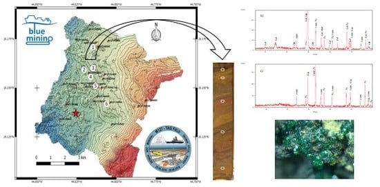
Graphical Abstract

1. Introduction

It is no novelty that mineralogical and geochemical information are both essential to providing an early assessment of the ore potential of an exploration area. The application of cost-effective techniques to analyze offshore materials from exploration target areas (i.e., in near-real time) and thus acquire mineralogical and geochemical information in order to provide a preliminary ore potential is a prerequisite for fast and efficient regional exploration [1]. Operations such as these will be essential in creating the knowledge necessary for larger scale ventures.
Due to the increased demands of our modern technological world, and with the definition of sustainability goals for 2030, global society needs for critical raw materials (CRMs) are expected to grow rapidly. There is an opportunity to explore the seafloor for critical (and non-critical) resources, including mid-ocean ridges that may contain appropriate CRM resources. Knowledge about the distribution and grades of marine mineral resources on the ocean floor is particularly limited to seafloor massive sulfide (SMS) deposits, which occur along mid-ocean ridges. The Mid-Atlantic ridge (MAR) hosts 19 known SMS fields in different geological settings, of which the Trans-Atlantic Geotraverse (TAG) hydrothermal field, discovered by Rona et al. [2], is tectonically controlled and one of the largest known SMS deposits [3,4,5,6]. The TAG hydrothermal field consists of a number of SMS deposits that include the active high-temperature TAG mound and active low-temperature Shimmering mound, as well as inactive sulfide mounds such as the large MIR, Double, and Shinkai mounds [7,8]. It is of crucial importance to elucidate the compositions and formation of mineral deposits from older and colder relicts (e.g., Double, Shinkai and MIR mounds) to active deposits (Shimmering and active TAG mounds).
Most studies of mineral deposits, including those regarding active TAG mounds, have been determined onshore by X-ray powder diffraction (XRD) in conventional laboratories [9,10,11,12,13]. Available XRD studies have been performed with dry powder mounts, generally without any pre-treatment of samples to remove calcite. The only study in which sodium acetate buffer (1N) was used to eliminate carbonate phases from sediment samples of the TAG field was that of Severmann et al. [13]. However, this was done onshore, and no data on stoichiometry nor on buffer solution characteristics were provided.
The offshore X-ray powder diffraction (XRD) identification of minerals for deep-sea mineral exploration was been developed as a part of the EU-FP7-funded project “Blue Mining-breakthrough solutions for sustainable deep sea mining”. In this work, rapid, exploration-oriented, integrated XRD methods are described for the mineralogical study of deep-seafloor sediments. The carbonated samples method of sequential extraction with acetate buffer was developed for the rapid analysis of minerals based on a low or high initial content of calcite in samples. To the best of our knowledge, no similar studies have been reported. Fieldwork was conducted during the expedition M127, aboard the German research vessel Meteor, throughout the TAG hydrothermal field (26° N, MAR) during May–June 2016. All on-board results were validated later, onshore, by conventional XRD analysis under fully fledged laboratory conditions. The results were exactly the same as those obtained offshore.

2. Materials and Methods

2.1. Sample Collection and Labeling

During expedition M127, the selection of suitable sediment ponds for gravity coring was based on a distal/regional location from the known hydrothermal mounds with the intent to study/identify concealed mineralized masses in the TAG hydrothermal field (Figure 1). The selection of possible coring stations was largely based on preexisting bathymetric data. In total, 21 gravity cores (GCs) were recovered with sediments varying from 20 cm (GC-638) to 313 cm (GC-627) in length. Gravity corers were collected from water depths between 3000 to 3753 m (Figure 1). Five cores were collected in the northern part of the TAG area in the Shimmering mound: GC-626, GC-681 and GC-682 were taken from proximal areas, and GC-576 and GC-690 were taken from distal areas. The cores GC-616 and GC-617 were collected in the eastern part of the Southern mound, whereas GC-636 was obtained 900 m SW of this mound. The GC-702 was collected about 100 m SW and SE of the inactive Shinkai mound and Double mound, respectively. Cores GC-627, GC-644, GC-647 and GC-703 were recovered from the Central area. At the MIR zone, cores GC-649 and GC-692 were collected in proximal areas, but four corners were also recovered from more distal zones: GC-666 and GC-691 were collected around 2000 m NE of the active area and GC-645 and GC-615 were collected 800 m NW and 1200 m SE of the active area, respectively. GC-693 was located 800 m NW of the high-temperature active TAG mound, while GC-638 was located approximately 1000 m SE of the active TAG mound.
Upon recovery on deck, the core catcher (CC) was removed and the core liners were cut into 1-m sections. The core sections were subsequently transported to the cold laboratory for pore water extraction and afterwards to the Geolab for further work [15]. The subsamples collected for onshore treatment and archive/working core halves were stored in plastic sleeves within a nitrogen atmosphere to prevent sulfide oxidation. Nitrogen was introduced by air gun followed by sealing the sleeve.

2.2. Sample Monitoring and Pre-Treatment

The core sections were carefully split lengthways using a circular power saw. After opening the cores with a fishing line wire (hard nylon), the sediment was monitored using a Spectrophotometer CM-700d/600d (Konica Minolta, Warrington, United Kingdom) to obtain light reflectance parameters. The lightness parameter belongs to the CIELAB (Commission Internationale de l’Eclairage) color description system (CIELAB), which uses three coordinates (L*a*b*) to locate a color in space. The CIELAB system uses a spherical coordinate system, with one of the axes being the lightness value (L*) ranging from 0% to 100%, and the other axes being the chromaticity variables a* and b* (a* is the green to red axis and b* is the blue to yellow axis). Lightness was measured with recommended parameters setup 10°/D65, where D65 refers to average daylight as a standard illuminant.
In the center of the working half along the core, a portion of sediment was sampled by a cut-off, tip-less plastic syringe, then dried in an oven at 35 °C for several hours (5 h on average). Subsequently, at selected depths, the working half was sub-sampled for later onshore work. For all samples pH, redox potential and temperature were registered by a portable multimeter analyzer (Hach Lange senSION MM110, Berlin, Germany).
After drying, samples were ground in an agate mortar and pestle. Depending on the sample heterogeneity (observed visually by differences in color) and on monitored screening parameters, various samples were selected from each core and analyzed by the Spectrophotometer without any further pre-treatment step. At least one sample rich in carbonate ooze was analyzed from each core, but mineralogical work was concentrated on hydrothermally influenced samples (e.g., up to 20 samples were analyzed per core in the Central area, see Figure 1 and Table 1, Section 3).

2.3. Sequential Extraction of Carbonates

Information about the presence of minor mineral phases in samples rich in carbonate ooze can be flawed due to the presence of calcite, which in XRD analysis produces peaks overlapping with those of important minerals such as sulfides, sulfates or oxyhydroxides. Moreover, the most abundant reflection of calcite at d = 3.03 Å (Calcite 104) “masks” characteristics and the less abundant, peaks of other minerals, particularly clay minerals [16]. Therefore, in carbonated samples, sequential extraction must be applied to remove calcite in order to be able to identify the minor phases. Sequential leaching was performed onshore, but could easily be performed onboard.
The method of sequential extraction with sodium acetate solution was first applied to sediment samples by Tessier et al. [17], when it was demonstrated that buffer solutions with pH values lower than 5 could affect the structure of mineral phases. Namely, extraction with HCl or acetic acid at a concentration of 2.5% and a pH of 2.5 led to the partial attack of Fe and Mn oxides. Therefore, the use of acetate solution with a pH of 5.0 will have minimal impact on other minerals such as silicates, oxides and sulfides. The use of sequential extraction provides an effective dissolution of carbonates without attacking the minor mineral phases. However, in the presence of low crystallinity phases, the buffer solution may be excessively active. Some phases may be dissolved, preventing their detection.
With the aim of removing carbonates and identifying minor minerals in carbonate-rich samples, we optimized the method of sequential extraction with previously prepared composite standards prior to the cruise. The standards were prepared by mixing pure crystals of calcite, hematite, pyrite and chalcopyrite (min 95.0%, MinLab, Lisbon, Portugal) in different proportions. Initially, the minerals were crushed in a stainless steel Abich mortar and the obtained particles were finely ground in an agate mortar with addition of few drops of ethanol, as grinding aids. Each pure mineral powder obtained in this way was kept in a plastic vial. The base mixtures of minerals in certain proportions were homogenized in a vial by vigorously shaking them for a few minutes. Two composite standards containing calcite, hematite, pyrite and chalcopyrite were prepared “in house” in the following proportions: 39.7%, 28.3%, 26.3%, 5.8% (standard CS-A) and 84.4%; 7.3%; 6.8%; and 1.5%, respectively (standard CS-B). We used previously analyzed (chemistry and XRD mineralogy) sediment samples from the Saldanha hydrothermal field as in-house standards. These were collected during the research cruises Seahma I and CD 167 [18,19], and quantity of calcite in these sediment samples corresponded with the ones used for the composite standards prepared. We used lower (39.7%) and higher concentrations (84.4%) of calcite in the composite standards.
Sodium acetate, anhydrous (min 99.0%, Merck, Darmstadt, Germany) and acetic acid (min 99.5%, Sigma-Aldrich, Darmstadt, Germany) were used to prepare the buffer solution for extracting carbonates. About 1 g of each sediment sample (dry weight) was dissolved in 30 mL of sodium acetate adjusted to pH 5.0 with acetic acid in a polypropylene centrifuge tube (50 mL) to minimize loss of solid material. Five hours of extraction were sufficient for complete dissolution. After extraction, separation was accomplished in a mid-desktop centrifuge (Megafuge 1.0, Heraeus, Buckinghamshire, UK) equipped with a rotor sealed in four places (each with 3 tube positions), which allowed the fast separation of high sample volumes at 3000 rpm (in 5 min). The respective supernatant was removed, whereas the sample residue was washed with 30 mL of distilled water. After another centrifugation step, the supernatant was discarded and the rest of the sample was dried at 35 °C. For composite standards with higher amounts of calcite, a second dose of fresh buffer solution was added to complete the dissolution step, and the supernatant was discarded following the same procedure previously described.

2.4. XRD Analysis of Seafloor Sediment Samples

The instrument operating conditions that were selected for mineral identification were focused on the development of an efficient methodology for real-time data acquisition to provide time-effective exploration tools offshore. Thus, in the Laboratory of Mineralogy, Faculty of Sciences, University of Lisbon (Lisbon, Portugal), previously characterized sediment samples (Saldanha hydrothermal field; 36°34′ N, 33°26′ W) collected during the research cruise Seahma I (L’Atalante vessel and Victor 6000 ROV) and the RV Charles Darwin cruise CD 167 [18,19] were analyzed using a portable desktop X-ray diffractometer (MiniFlexII, Rigaku, Tokyo, Japan) equipped with a MiniFlex2+ goniometer and detector. CuKα1 radiation (1.541 Å) was operated at an applied voltage of 30 kV, with a 15 mA beam current.
A standard plate of pure silicon was used for calibration of the X-ray diffractometer, measuring 2θ positions of characteristic peaks in order to perform angle corrections (a runtime of approximately 80 min). The measurement conditions showed various peaks that were automatically calculated, and the differences between the default and measured values were found to be less than 0.1° for the respective 2θ°.
All samples were analyzed in glass slide holders (because of the better sensitivity of diffractograms) that were uniformly pressed, assuring a perfect distribution of suitably compressed dry powder. The 2θ incidence angles spanned from 5° (start angle) to 60° (stop angle), with a scan speed of 1.2° per minute using the continuous scan mode. The total runtime for the analysis was optimized to be 45 min per sample. Before running the samples, instrumental calibration was performed by running a quartz standard and thus ensuring the 2θ positions in the diffraction pattern corresponded to characteristic peaks of the mineral.
Obtained raw files were transformed with the PowDLL program (v. 2.53.0.0, N. Kourkoumelis, University of Ioannina, Ioannina, Greece) to binary scan.rd format and further transformed into binary peaks.di documents by X’Pert Plus, which were readable for direct mineral analysis by the in-house developed software ‘XRD Identify’ [20]. Smoothing was performed by applying Savitzky-Golay’s digital filter, and after background subtraction and Kα2 elimination, peak search was automatically run by a minimum second derivative. Only the peaks with relative intensities higher than 20 counts were considered relevant for mineral identification.
The XRD Identify studio software was designed to assist the interpretation of diffracted mineral powder data [20]. The program interprets X-ray diffraction patterns characterized by complex, overlapping peak registers, which are traditionally difficult to sort out. As a standard, this software used the ASCII PDF-2 commercial database published by the Joint Committee on Powder Diffraction Standards–International Centre for Diffraction Data (JCPDS–ICDD).

2.5. Quality Control

2.5.1. Optimization of Extraction Method for Removing Calcite

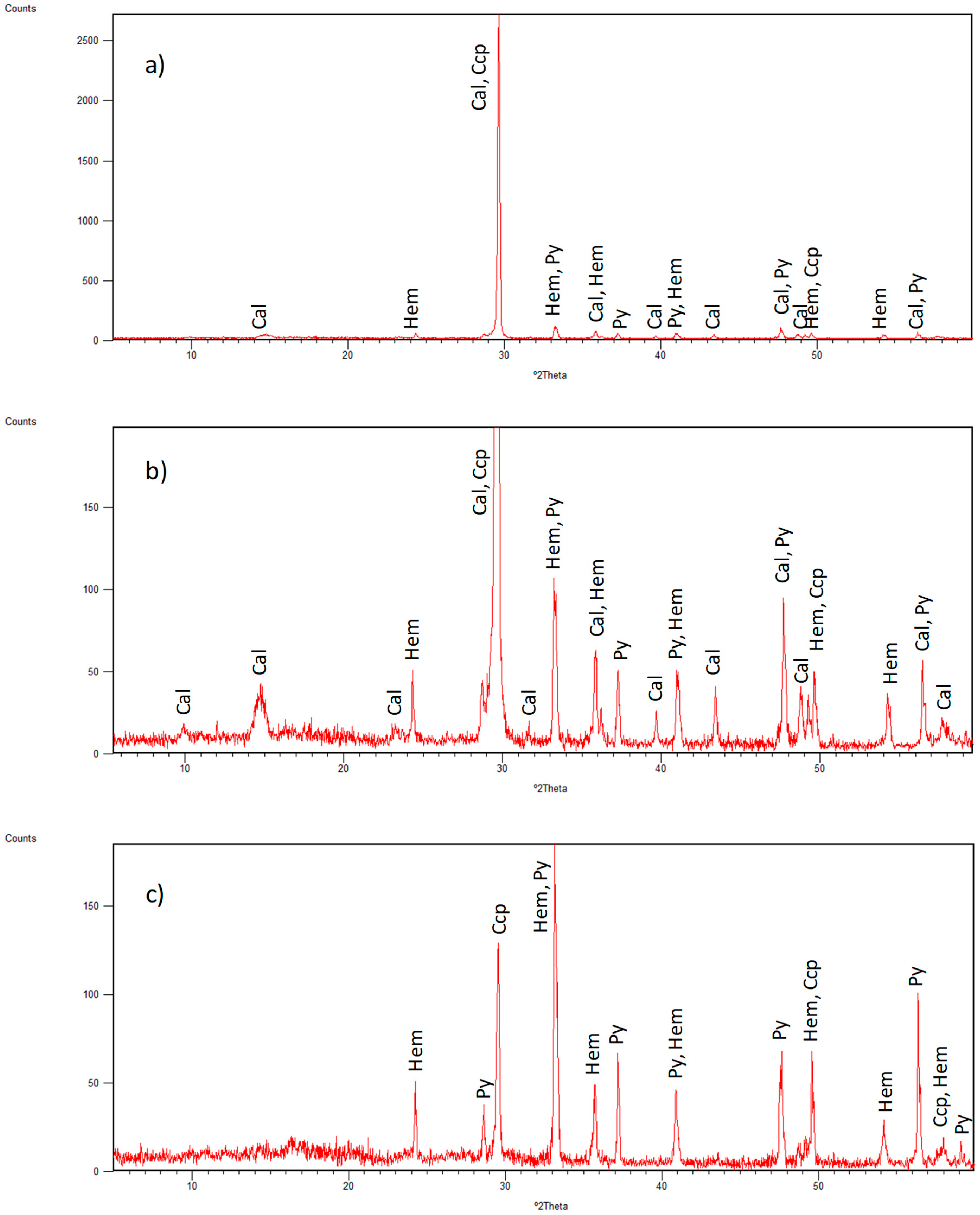
To test extraction efficiency, composite samples prepared from pure mineral standards were used (CS-A and CS-B; see Section 2.2). XRD patterns obtained by running the CS-A before and after the treatment with sodium acetate buffer are shown in Figure 2 as an example. In the original composite sample, only characteristic peaks of calcite (CaCO3) could be observed, and the strongest reflection of calcite (diffracting plane 104 at 29.42°) practically “masked” all other peaks associated with minerals originally present in the sample (Figure 2a). In Figure 2b, the depicted Y-axis scale (with the same span as Figure 2c) shows that calcite peaks could be detected almost exclusively in the untreated (original) sample.
The XRD pattern of treated CS-A shows that typical calcite (Cal) peaks were eliminated after applying the extraction, including those at 39.43°, 43.18° and 48.51° (Figure 2c). Thus, characteristic peaks for hematite (Hem) and pyrite (Py) (at 33.20° and 33.09°, respectively) increased for more than 50%, after the extraction method was applied. The typical peaks for pyrite became visible only after treatment with buffer, and its presence was confirmed by characteristic bands at 28.55°, 56.35° and 59.10° (note that the peak at 28.55° in the original sample could not register as it completely overlapped with a broad and intense Cal reflection at 29.42°). Chalcopyrite (Ccp), present in a small amount in CS-A (5.8%), was detected at 29.40° (overlapping with the most intense reflection of Cal) only after the removal of calcite. An additional Ccp peak (at 49.06°) became more visible after the buffer attack (in order to avoid misinterpretation with Cal, the most intense peak of Ccp at 29.40° was not considered as the only confirmation peak).
To better explain calcite extraction, we used the quantitative ratio between Cal at 104 intensities in the original (Iorig) and treated (Itreat) samples: Iorig/Itreat, as an empirical parameter for the evaluation of efficiency of calcite removal from the original sample. In this case, the ratio of XRD intensities was equal to 24.5, which was enough to identify other mineral phases in the prepared composite samples (CS-A).
The CS-B standard was prepared with a much higher content of calcite (84.4%), and the first treatment with the sodium acetate buffer resulted in a low ratio of Iorig/Itreat (equal to 2.75), which was not enough to eliminate Cal and identify other minerals. After the addition of the second dose of buffer, the ratio was three times higher (Iorig/Itreat = 8.25), and only after the addition of the third dose of buffer were the typical peaks of Cal eliminated (Iorig/Itreat = 24.2), allowing the other three minerals in CS-B (i.e., Ccp, Hem and Py) to be detected. In samples with higher contents of calcite, several doses of fresh buffer addition were necessary to quantitatively extract carbonates and permit the detection of other minerals. Therefore, the degree of calcite XRD signal decrease the treatment with sodium acetate buffer was considered to be the critical parameter determining the possibility of identifying other minerals in carbonated samples. Higher values of Iorig/Itreat (>24) indicated the quantitative removal of calcite, permitting the detection of other minerals in mixtures.

2.5.2. Validation of Mineral Identification

The validation of crystalline phases was carried out after the M127 cruise at the Instituto Superior Technical-University of Lisbon (Portugal) with a conventional X-ray diffractometer (PANalytical X’PERT Pro model) using CuKα radiation. The measurement parameters used were similar to those previously established with a 2θ range: 5–60°, step size 2θ = 0.033° and scan speed of 0.029 s, with generator settings of 35 mA and 40 kV. The total runtime for each analysis was about 35 min.
The verification of identified minerals was performed by the software X’Pert High Score Plus with an updated PDF4 database (International Center for Diffraction Data, 2017). In this way, the database was used for the qualitative identification of mineral phases in analyzed samples, as well as for the validation of previously obtained offshore XRD results. Some of the XRD patterns of studied sediment samples (GC-627/B-151, GC-627/A-220 and GC-682/A-220) with identified mineral phases are presented in Figures S1–S3.

2.6. Time Constraints Related to Identification of Minerals during Cruises

As previously explained, for the X-ray diffraction analysis of sediments, samples should be dried, ground and homogenized prior to mineral analysis (see Section 2.2). Sample drying is a time-consuming step, since the temperature should be kept at 35°, to prevent the destruction of the clay mineral structure and thus bias the mineralogical analysis. Our results showed that, on average, about 5 h were enough to dry the samples before they reached a constant mass. The grinding step was performed until no asperity was felt, and this pre-treatment step took at least 5 min per sample. The grinding was accelerated by adding a few drops of ethanol. Each XRD analysis took approximately 45 min in order to complete mineralogical identification.
To apply the optimized sequential extraction to the carbonated samples, an extra 5 h was necessary for the reaction with the buffer solution to occur; then, after centrifugation (5 min), another 5 h of drying was necessary before running the XRD analysis. For samples with higher carbonate contents, an additional extraction step was needed, resulting in a 10 h process (5 h for the buffer attack and 5 h for the sample drying). All these time constraints were improved onshore, but could be applied for the more-efficient XRD identification of minerals during cruises.

3. Results and Discussion

The main values of physicochemical parameters measured in core sediment samples (n = 107) are presented in Table 1. In terms of pH, all sediment samples were very similar, and were neutral to slightly basic with a narrow range of pH values (i.e., from 7.03 (GC-682-A-202) to 8.15 (GC-692-CC)). Slightly acidic properties were visible in samples of the core GC-702, with pH values from 6.31 to 6.74 (Table 1). The measured values for redox potential (Eh) varied from -195 mV (GC-647-C-64) to 339 mV (GC-682-B-155), showing that different reactions can occur in sediments. As an example, under oxidative conditions (Eh > 0 mV), a reduced form of metal ions is more stable (e.g., Fe2+ and Mn3+), whereas under redox conditions (Eh < 0 mV), sulfide formation is more favored (S2−).
As can be seen in Table 1, most of the cores exhibited a highly carbonated appearance, whereas few of them showed evidence of hydrothermal influence. However, in the vicinity of the Central area cores (GC-627, GC-644, GC-647) showed brown-red-orange layers with dark Mn oxides. Near the Shimmering mound, two cores (GC-681, GC-682) showed Mn- and Fe-oxide breccia layers.

3.1. Identified Mineral Phases in Carbonated Sediment Samples

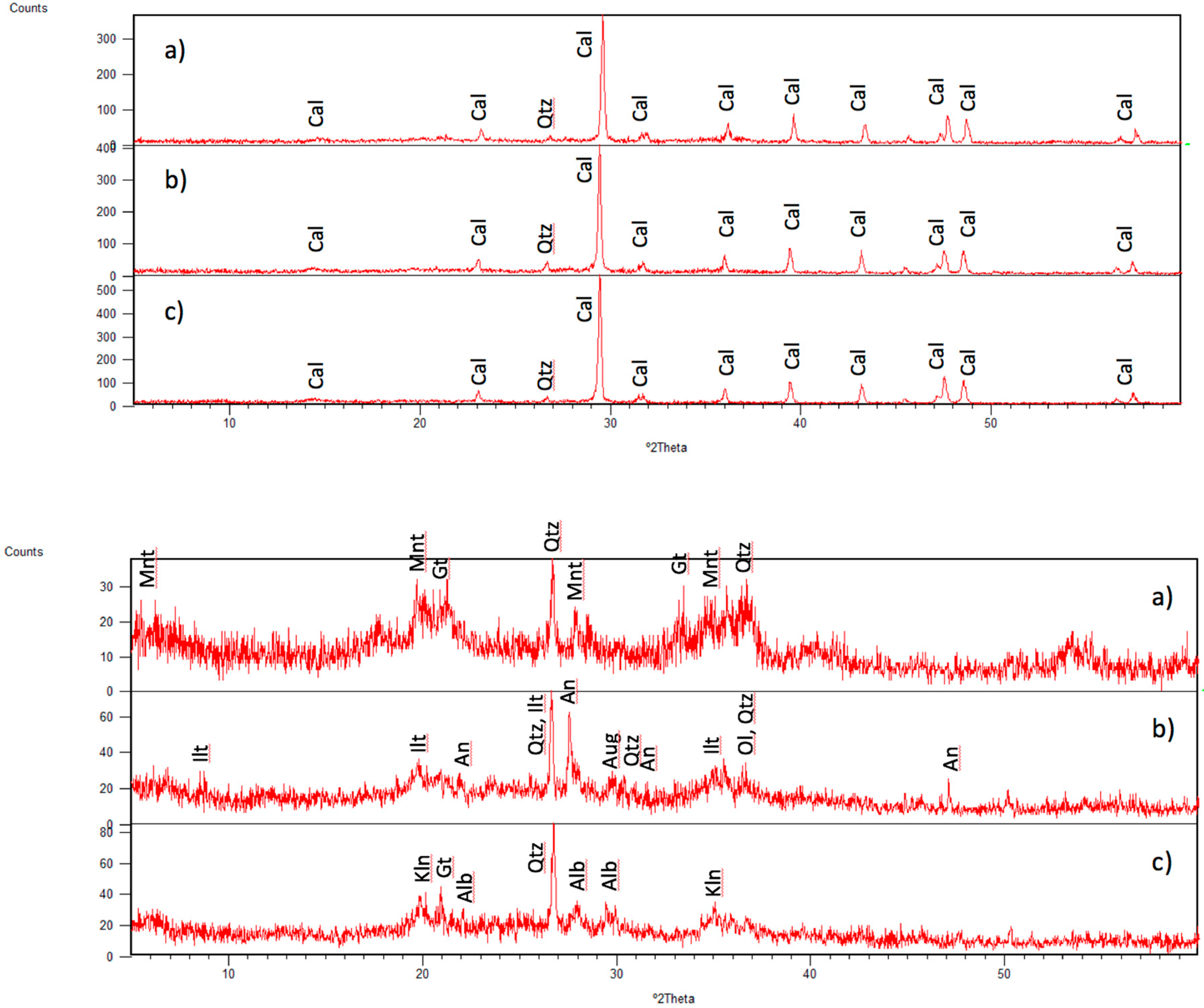
All sediment subsamples from carbonate-rich cores (Section 2.1) are characterized as pale brown to brown in color, with grain sizes of sandy silt and irregular patches due to bioturbation in sediment overlying the basaltic pillow lava substrate. Out of the more than 100 samples studied, 42% of them were carbonate-rich samples (n = 45), and their relative intensities of the highest reflection of Cal (at 29.42°) ranged from Iorig: 274 to 396 counts. Three samples of cores (GC-627, GC-690 and GC-681) are shown in Figure 3 as an example. Except for the presence of small peaks of quartz (Qtz) at 26.66°, the calcite peaks masked all other minor minerals and, hence, could not be identified in the original diffractograms.
After the sequential dissolution of calcite the intensities of the main calcite peak (104) were strongly reduced and the obtained diffractograms of the chemically treated samples permitted the identification of other primary mineral phases. As can be observed, obtained peaks were of less intensity, ranging from 30 to 80 counts (Figure 3a,c, respectively), indicating a poor abundance of detected minerals. In general, carbonate-rich samples also contain Al-rich and Fe-rich clays such as illite (Ilt), kaolinite (Kln), montmorillonite (Mnt), nontronite (Nnt) and so on, as previously reported in the TAG [10,11,12,13] and other seafloor hydrothermal deposits [15,18,19,21,22]. Nontronite (Fe-Al-smectite) was found in two samples near the low-temperature Shimmering mound (681-CC and 682-CC), where its formation was favored under neutral to slightly basic pH and at low temperatures in low Eh conditions when Fe and Si were present in the solution [13,23]. Besides clays, quartz and albite (Alb), goethite (Gt) was also found in most of the cored samples from the Central area (GC-627, GC-644, GC-647, GC-703; see Figure 1), as well as near the MIR (GC-692) and Shimmering (GC-702) mounds. The presence of Qz, Alb and Gt were driven by basaltic fragments and might have been be included in small fragments in the sediment. The formation of Gt may be associated with higher Eh values and the presence of Fe3+ [13,23]. In most of the cores, goethite (Gt) was evenly distributed, with the exception of GC-644 and GC-682, where it was detected in deeper cored samples (i.e., GC-644/A-225, A-235, A-269 and GC-682/A-198, A-209, A-220).
Some of the clay minerals (in the bottom of cores) were probably directly derived from underlying basalts due to an alteration of magmatic minerals. Igneous plagioclase was either albitized (681-B-190) or partly replaced by anorthite-rich secondary plagioclase in the core catcher of sample GC-690 (Figure 3). Barriga et al. [24] identified hydrothermal anorthite in Troodos ophiolite, and Venko et al. [25] identified it in ODP hole 504B (Costa Rica Rift) and in Oman ophiolite. Aragonite-rich plagioclase was the main mineral fraction in most core catcher samples, which is in accordance with the results of Honnorez [26]. Moreover, in sample 649-CC, which was proximal to the inactive MIR mound, this was the only mineral that could be identified.
Along the gravity cores collected from locations with hydrothermal influences, several samples of the Central zone and proximal to the Shimmering mound had high carbonate contents that were evenly distributed (GC-627/B-184 and GC-681: C-30, C-80, B-190, A-250; GC-682: C-10, C-78, respectively; see Figure 1), with high intensities of Cal reflection (Iorig > 234 counts). The mineralogy detected in these samples was characterized by abundant clay mineral fractions (such as kaolinite (Kln), montmorillonite (Mnt), nontronite (Nnt)), augite and anorthitic plagioclase, while quartz (Qtz) and goethite (Gt) could also be identified in some of them.
Several samples from the Central area showed intermediate contents of calcite (e.g., GC-627/C-43, B-151; GC-644/C-52, C-60, C-70; GC-647/B-184; see Figure 1). Similar contents of Cal were found in samples near the MIR zone and proximal to the Shimmering mound, with Iorig ranging from 4 (GC-682/B-116) up to 156 counts (GC-649/A-167). After the extraction procedure was applied, the mineral fraction that could be detected from the XRD pattern was attributed to goethite (Gt), halite and quartz (Qtz). Moreover, the presence of hematite (Hem) was confirmed in sample GC-647/B-184, which was proximal to the Double mound (see Figure 1). Since amorphous phases are commonly present in plume Fe-rich fallout and in primary Fe oxyhydroxides, we could detect them as broad scattering profiles in the backgrounds of the originally obtained XRD patterns of studied samples.

3.2. Correlation between XRD Intensity of Calcite and Lightness

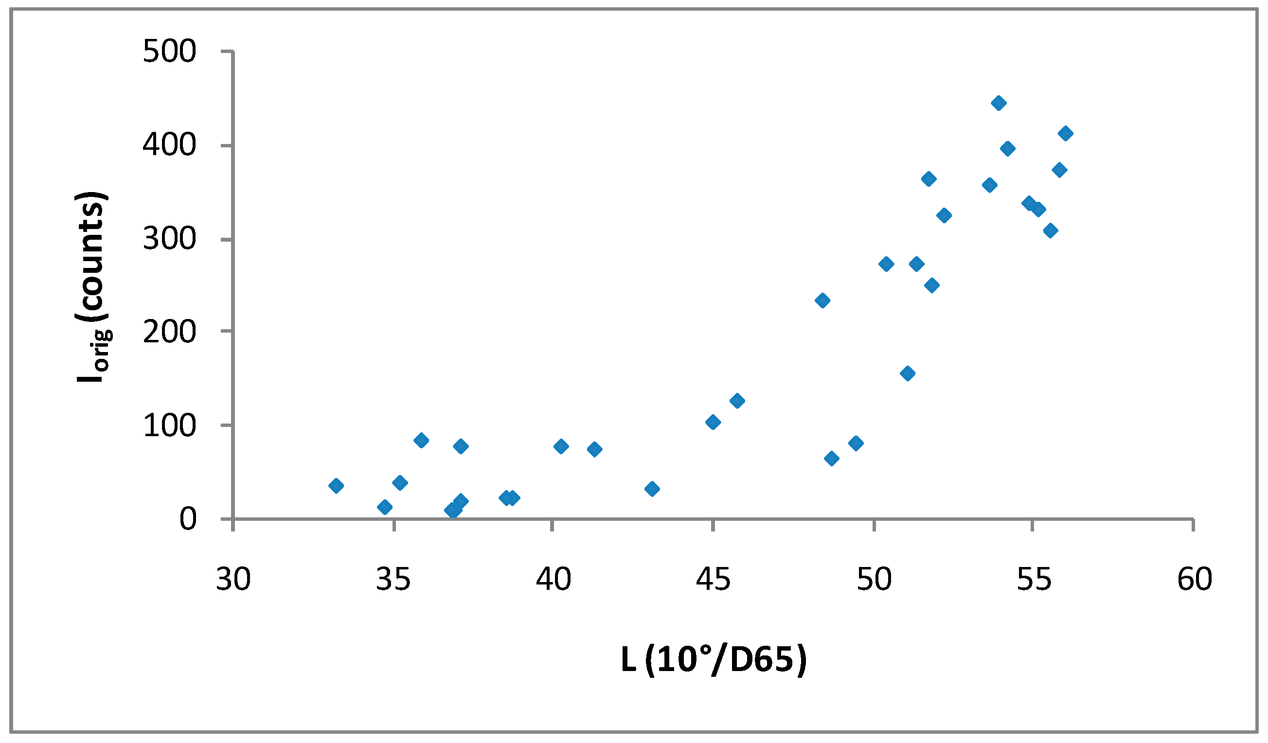
The lightness parameter (L*) has been used for a long time as a reasonable proxy for carbonate content in sediment cores [27,28]. In analyzed samples from the TAG field, a relationship between relative calcite XRD peak intensities (with a reflection of the 104 calcite peak) and the lightness parameter (L*) in sediments could be also observed [27]. The lightness measured directly on the cored samples and carbonate content can be described via the two-step model depicted in Figure 4: for the samples with lower carbonate contents (Iorig < 100 counts), which corresponded approximately to less than 20 wt% of Cal, there was a 0-slope linear trend between two variables, indicating negligible changes in Cal XRD intensity (I104) with sediment lightness (L*). Samples with higher carbonate contents (Iorig > 100 counts) (i.e., those with more than 20 wt% of Cal), were characterized by a positive correlation (R = 0.74, p = 0.05) between Cal intensity (I104) and sediment lightness.
Hence, in this particular scenario, the lightness of sediment could be useful to initially estimating the content of calcite (high- vs low-carbonated samples), which is very important when considering of the number of extraction steps with acetate buffer. In our sample suite (Figure 4), a single step of buffer treatment would be enough to remove calcite for sediments with a lightness of L* < 45, whereas in cases of L* > 45 at least two buffer treatments would need to be performed. Thus, for samples with a higher value of L* (>45), XRD would need to be run after two buffer treatments and, depending on the deduced Iorig/Itreat value, at least one more extraction step would need to be performed before the final mineral identification (see Section 2.5.1). The presence of calcium carbonate in samples was confirmed by a simple preliminary test with a few drops of diluted hydrochloric acid (1M HCl). The presence of other (white) minerals that could interfere with Cal and influence the value of the L* (such as sulfate) was considered negligible, because it was not detected in the TAG field [9,10,11,12,13].
This model could be particularly useful for detecting metal-bearing minerals spread by hydrothermal plumes that later precipitate in carbonated pelagic sediments. This would be most useful for constraining metallic anomalies (related to sulfide and oxide minerals) in oceanic sediment layers, and could contribute to discovering new hydrothermal fields (especially if they are inactive). Other minerals (such as sulfates) could interfere and contribute to the sediment lightness, leading to false positive results when interpreting calcite concentrations. However, the precipitation of sulfates from buoyant plumes is not expected away from vents, as the physico-chemical conditions of the plumes do not favor the transportation of sulfates.

3.3. Mineral Phases Identified in Hydrothermal Samples

Samples with strong hydrothermal influences were analyzed faster (without any extraction step), and their compositions varied strongly along the core. Selected samples of different textures were assessed offshore, with some of the results elaborated upon below.
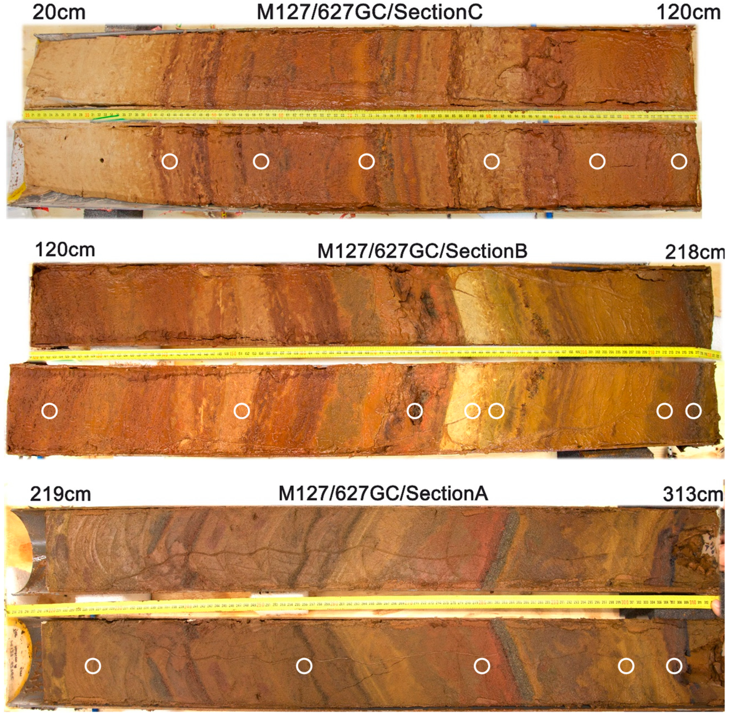
A representative core from the Central zone (Figure 1) that was distal to massive sulfide mounds consisting of four consecutive sections (D, C, B, A) of GC-627 (NW of the MIR zone and Central area) is presented in Figure 5. As can be seen, the four sections were heterogeneous: the top 40 cm contained pelagic sediment of a light brown color on top that became darker towards the bottom of the layer with some bioturbation. In the rest of the core (Sections C–A), repeating series of brown-red-orange silty-sandy sediment layers with some sulfide beds were present. The sulfide-rich sediments, forming mm- to cm-thick layers, were composed of silty to coarse sulfide crystals of dark colors. When the nontronite (or olivine minerals) are very fine grained, the sediment became green olive in color (sample GC-627/A-283).
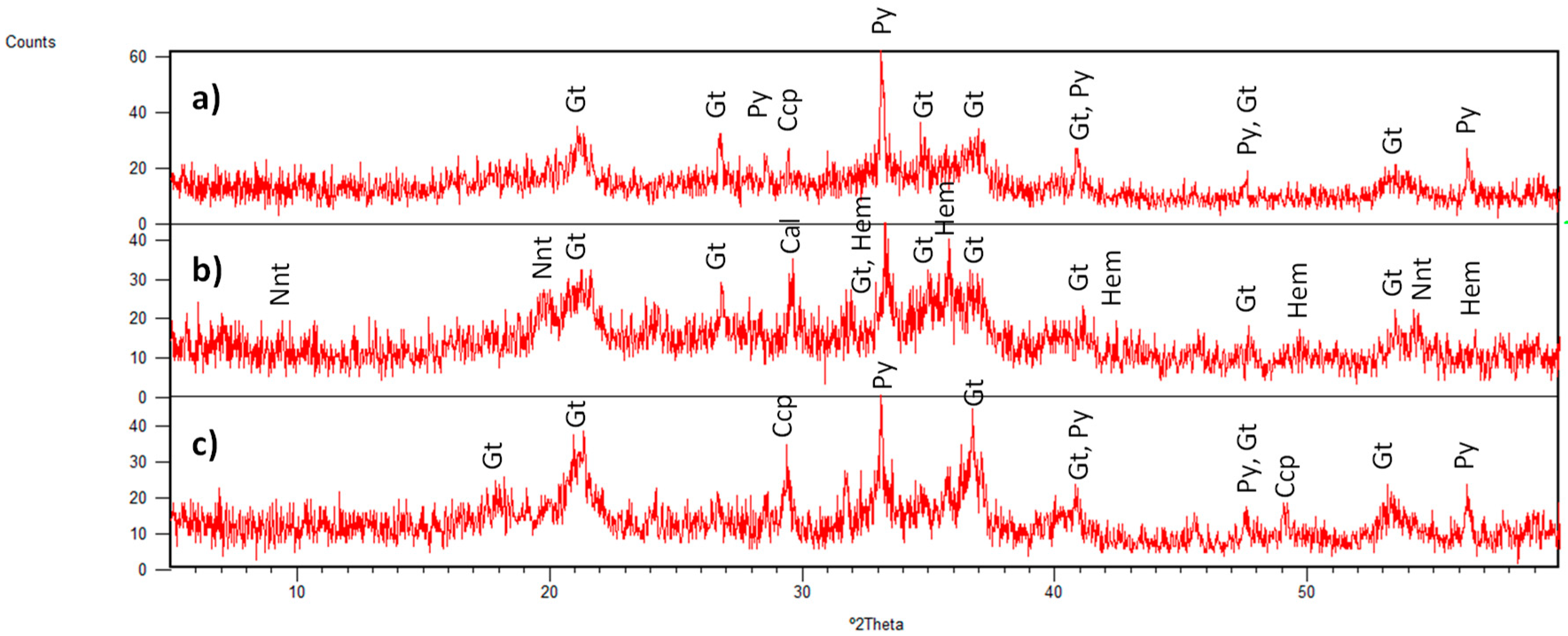
XRD analyses confirmed that the hydrothermal sediments were characterized by the presence of chalcopyrite (Ccp), goethite (Gt), hematite (Hem), pyrite (Py), quartz (Qtz) and nontronite (Nnt). Typical XRD patterns of three samples in the GC-627 are presented in Figure 6. As can be observed, poor crystalline mineral specimens were represented by low-intensity reflectance bands (Iorig < 65 counts).
Hydrothermal sediment occurring close to the massive sulfide mounds commonly consisted of orange-brown silt layers, revealing a high content of Fe-bearing phases that were oxidized as a result of contact with seawater. A disturbed core collected from the base of the Shinkai mound was sampled by GC-702 and showed some greenish patches (Figure 7).
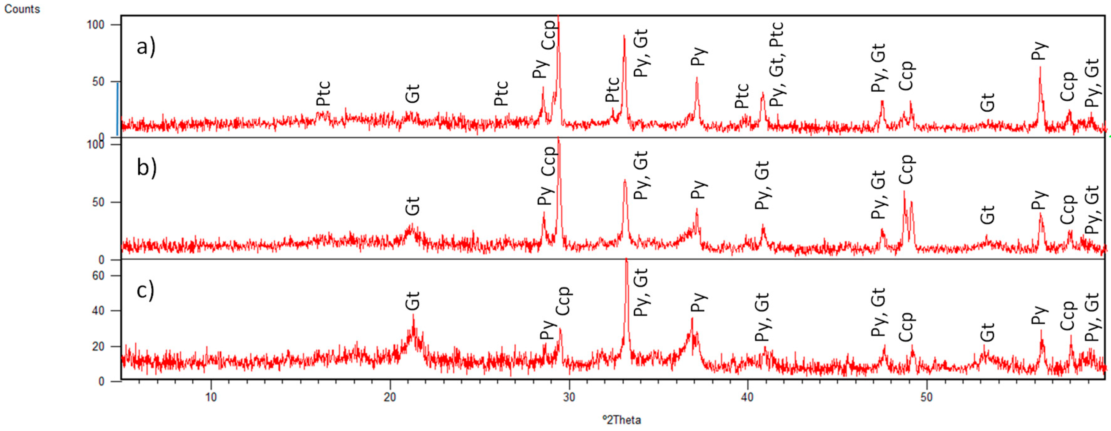
The XRD patterns obtained for three samples of this core indicated the presence of chalcopyrite (Ccp), as presented in Figure 8.
Chalcopyrite (Ccp) was also identified and its well-crystallized phase was confirmed in all three subsamples by peaks (at 29.40°, 48.67° and 57.87°) (Figure 8). The top 30 cm (Figure 8b) showed a higher content of chalcopyrite, whereas the deepest sample, at a depth of 53 cm (Figure 8c), contained less of this mineral. Furthermore, minerals of the atacamite group were described onboard in the top-most layer (GC-702-A-20) and later confirmed by XRD analysis onshore to be paratacamite (Ptc, (Cu,Zn)2(OH)3Cl) with its characteristic peaks at 16.20° and 28.40° (Figure 8a). The presence of this Cu-chloride phase (Ptc) in the TAG field is attributed to the oxidation of Cu-rich sulfide minerals, largely chalcopyrite, in limited contact with seawater [10].
Besides this cupric chloride phase, other minerals such as goethite (Gt) and pyrite (Py) were identified (Table 2). Both phases were formed under oxidizing conditions (higher Eh values) as a weathering product of sulfide phases [22,23]. The mineral goethite (Gt) increased downcore, whereas the pyrite (Py) content significantly decreased (with peaks at 56.35° and 37.13°). In this case, the peak at 33.09° was not considered, as it is a common reflection of both minerals. Hence, our results suggest that the deeper pyritic layer was exposed to oxidation for a considerable timespan, enabling marked pyrite oxidation.
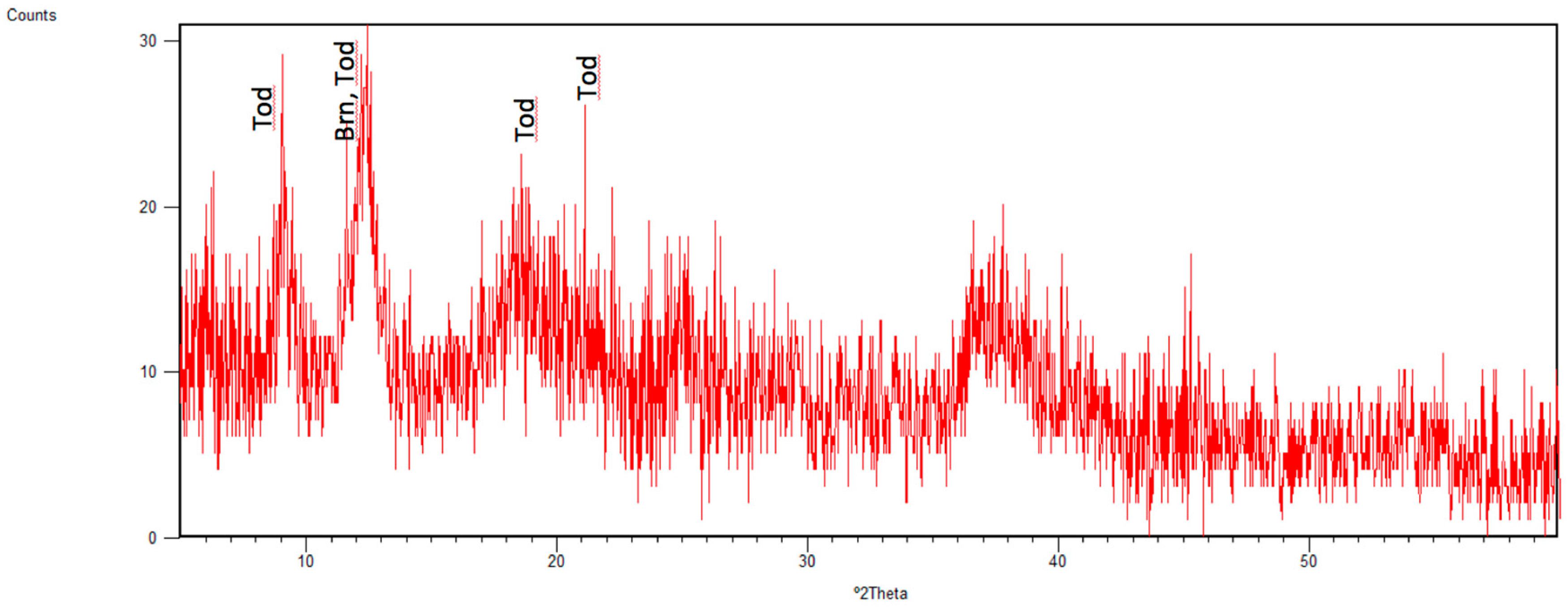
Brecciated metalliferous material was detected in samples collected near the MIR zone and were composed of Fe and Mn oxyhydroxides, clay minerals and sulfide material (GC-692, bottom of B and A sections). In GC-626-A-75 and GC-626-A-110 (Figure 9), collected near the Shimmering mound area, dark Mn-oxide breccia layers could be noticed, and the presence of Mn-minerals was confirmed by typical peaks in XRD patterns (sample GC-626-A-75 is presented in Figure 10). As can be seen, weak peaks with intensities not exceeding 30 counts designated poor crystalline quality of the sample. Similarly, black Mn-oxide sediment samples corresponding to dredged superficial crusts from the TAG-area were described by Thompson et al. [10].
The ferromanganese layers detected were predominantly composed of todorokite (Tod, MnO·H2O) and birnessite (Brn) and a variety of non-crystalline iron oxyhydroxides. Sedimentary Mn-enrichment, near the Shimmering active mound, can be tentatively attributed to the transport of Mn oxides via slumping processes [29,30].
The presence of birnessite was also confirmed in another sample near the Shimmering mound, GC-682-B-155, with the highest Eh being 339 mV. Both cores were in the Shimmering mound area, which is an actively venting low-temperature mound topped with low-temperature hydrothermal deposits [31,32]. Precipitation of Mn-oxide phases has important implications on the geochemical budgets of many other metals in solution, due to its potential to scavenge metals from solution [33,34].

3.4. Overview of Mineral Distribution in Sediment Cores at the TAG Field

The main mineral fractions identified in the analyzed deep-sea sediment samples, carbonated in either of the hydrothermally active cores from the TAG field, are listed in the Table 2.
From the overall listed minerals, calcite, goethite and quartz were identified as major phases in the majority of the analyzed sediment samples from the TAG field. Besides iron oxides such as hematite (Fe2O3), other minerals were detected as well including iron sulfides such as pyrite (FeS2) and Cu-bearing minerals, some of which have potential economic value such as chalcopyrite (CuFeS2). In a deep-sea sediment sample in Central area (GC-644/B-95), the mineral covellite (CuS), was identified. On the other hand, in a sample near the MIR zone (GC-702/A-20), the mineral paratacamite ((Cu,Zn)2(OH)3Cl) was detected. Hence, sulfides (Ccp, Py), silicates (Qtz) and filossillicates (Nnt) collected from different zones of the TAG hydrothermal field were the most abundant groups of minerals among the analyzed samples.

4. Conclusions

In this study, we elaborated on the ability of XRD studies to produce results fast enough to contribute to the development of research cruises at sea. The optimized method of sequential extraction with acetate buffer (pH 5.0) allowed the mineralogy to be efficiently determined in carbonated sediment samples. This may help in deciding how much work should be dedicated to each sediment core as a function of its lightness, which will be a measure of the carbonate abundance in samples. Thus, within 20 h it was possible to analyze a batch of 24 non-carbonated sediment samples (previously dried). In cases of carbonated samples, an additional step of buffer treatment was required for detailed mineralogy (after elimination of carbonates, which depends on the number of buffer iterations), necessitating an additional time of approximately 18 h/sample batch. Time constraints of highly carbonated samples should be addressed and studied in more detail in the future.

Supplementary Materials

The following are available online at https://www.mdpi.com/2075-163X/10/2/160/s1, Figure S1: XRD-pattern (and identified mineral phases) of the sample GC-627/B-151; Figure S2. XRD-pattern (and identified mineral phases) of the sample GC-627/A-226; Figure S3. XRD-pattern (and identified mineral phases) of the sample GC-682/A-220.

Author Contributions

Conceptualization, J.M. and F.J.A.S.B.; methodology, J.M., A.I.J., S.M. and M.F.C.P.; software, J.M. and S.M.; validation, J.M. and M.F.C.P.; resources, Á.A.D. and F.J.A.S.B.; writing—original draft preparation, J.M.; writing—review and editing, Á.A.D., S.M., S.P. and F.J.A.S.B.; supervision, F.J.A.S.B.; funding acquisition, F.J.A.S.B. All authors have read and agreed to the published version of the manuscript.

Funding

The work was done as part of the project “BLUE MINING–Breakthrough Solutions for the Sustainable Exploration and Extraction of Deep Sea Mineral Resources”, has received funding from the European Union’s Seventh Framework Programme (EU-FP7) for research, technological development and demonstration under Grant agreement Nº: 604500. The authors would like to acknowledge the financial support FCT through project UIDB/50019/2020–IDL.

Acknowledgments

The authors would like to thank to the M127 cruise team and to Geomar, Helmholtz-Center for Ocean Research (Kiel, Germany) for technical support during the oceanographic mission and for the AUV-derived, map of the TAG hydrothermal field. The authors would like to thank to Bramley J. Murton (NOC, Southampton, England) for constructive suggestions during the preparation of this research manuscript. The authors are thankful to the Editor of the Journal and to the reviewers.

Conflicts of Interest

The authors declare no conflicts of interest.

References

  1. Barriga, F.J.A.S. Can recycling and the circular economy render seafloor mining unnecessary? In Economical, Technological and Environmental Aspects: Cooperative Solutions for Future Deep-sea Mining; UMC, Federation of German Industries (BDI): Berlin, Germany, 2017. [Google Scholar]
  2. Rona, P.A.; Klinkhammer, G.; Nelsen, T.A.; Trefry, J.H.; Elderfield, H. Black smokers, massive sulphides and vent biota at the Mid-Atlantic Ridge. Nature 1986, 321, 33–37. [Google Scholar] [CrossRef]
  3. Tivey, M.A.; Schouten, H.; Kleinrock, M.C. A near-bottom magnetic survey of the Mid-Atlantic Ridge axis at 26° N: Implications for the tectonic evolution of the TAG segment. J. Geophys. Res. Space Phys. 2003, 108, 2277. [Google Scholar] [CrossRef]
  4. DeMartin, B.J.; Sohn, R.A.; Canales, J.P.; Humphris, S.E. Kinematics and geometry of active detachment faulting beneath the Trans-Atlantic Geotraverse (TAG) hydrothermal field on the Mid-Atlantic Ridge. Geology 2007, 35, 711–714. [Google Scholar] [CrossRef] [Green Version]
  5. Canales, J.P.; Sohn, R.A.; DeMartin, B.J. Crustal structure of the Trans-Atlantic Geotraverse (TAG) segment (Mid-Atlantic Ridge, 26°10′N): Implications for the nature of hydrothermal circulation and detachment faulting at slow spreading ridges. Geochem. Geophys. Geosystems 2007, 8, 1–18. [Google Scholar] [CrossRef]
  6. Fouquet, Y.; Cambon, P.; Etoubleau, J.; Charlou, J.L.; Ondréas, H.; Barriga, F.J.A.S.; Cherkashov, G.; Semkova, T.; Poroshina, I.; Bohn, M.; et al. Geodiversity of hydrothermal processes along the Mid-Atlantic Ridge and ultramafic-hosted mineralization: A new type of oceanic Cu-Zn-Co-Au volcanogenic massive sulfide deposit. Sea Ice 2010, 188, 321–367. [Google Scholar] [CrossRef] [Green Version]
  7. Rona, P.A.; Hannington, M.D.; Raman, C.V.; Thompson, G.; Tivey, M.K.; Humphris, S.E.; Lalou, C.; Petersen, S. Active and relict sea-floor hydrothermal mineralization at the TAG hydrothermal field, Mid-Atlantic Ridge. Econ. Geol. 1993, 88, 1989–2017. [Google Scholar] [CrossRef]
  8. White, S.N.; Humphris, S.E.; Kleinrock, M.C. New Observations on the Distribution of Past and Present Hydrothermal Activity in the TAG Area of the Mid-Atlantic Ridge (26°08′ N). Mar. Geophys. Res. 1998, 20, 41–56. [Google Scholar] [CrossRef]
  9. Dekov, V.; Damyanov, Z.; Kamenov, G.; Bonev, I.; Bogdanov, K. Native copper and α-copper–zinc in sediments from the TAG hydrothermal field (Mid-Atlantic Ridge, 26°N): nature and origin. Mar. Geol. 1999, 161, 229–245. [Google Scholar] [CrossRef]
  10. Thompson, G.; Mottl, M.J.; Rona, P.A. Morphology, mineralogy and chemistry of hydrothermal deposits from the TAG area, 26°N Mid-Atlantic Ridge. Chem. Geol. 1985, 49, 243–257. [Google Scholar] [CrossRef]
  11. Mills, R.A.; Wells, D.M.; Roberts, S. Genesis of ferromanganese crusts from the TAG hydrothermal field. Chem. Geol. 2001, 176, 283–293. [Google Scholar] [CrossRef]
  12. Humphris, S.E.; Tivey, M.K.; Tivey, M.A. The Trans-Atlantic Geotraverse hydrothermal field: A hydrothermal system on an active detachment fault. Deep. Sea Res. Part II Top. Stud. Oceanogr. 2015, 121, 8–16. [Google Scholar] [CrossRef] [Green Version]
  13. Severmann, S.; Mills, R.A.; Palmer, M.R.; Fallick, A.E. The origin of clay minerals in active and relict hydrothermal deposits. Geochim. et Cosmochim. Acta 2004, 68, 73–88. [Google Scholar] [CrossRef]
  14. Linke, P.; Lackschewitz, K. Autonomous Underwater Vehicle “ABYSS”. JLSRF 2016, 2, 79. [Google Scholar] [CrossRef] [Green Version]
  15. Petersen, S. RV METEOR Fahrtbericht/Cruise Report M127 Metal fluxes and Resource Potential at the Slow-spreading TAG Midocean Ridge Segment (26° N, MAR)—Blue Mining@Sea, Bridgetown (Barbados)–Ponta Delgada (Portugal), 25.05.–28.06. 2016 (Extended Version); Berichte aus dem GEOMAR Helmholtz-Zentrum für Ozeanforschung Kiel: Kiel, Germany, 2016. [Google Scholar] [CrossRef]
  16. Środoń, J.; Drits, V.A.; McCarty, D.K.; Hsieh, J.C.C.; Eberl, D.D. Quantitative X-ray diffraction analysis of clay-bearing rocks from random preparations. Clays Clay Miner. 2001, 49, 514–528. [Google Scholar] [CrossRef]
  17. Tessier, A.; Campbell, P.G.C.; Bisson, M. Sequential Extraction Procedure for the Speciation of Particulate Trace Metals. Anal. Chem. 1979, 51, 844–851. [Google Scholar] [CrossRef]
  18. Dias, Á.S.; Früh-Green, G.L.; Bernasconi, S.M.; Barriga, F.J.A.S. Geochemistry and stable isotope constraints on high-temperature activity from sediment cores of the Saldanha hydrothermal field. Mar. Geol. 2011, 279, 128–140. [Google Scholar] [CrossRef]
  19. Dias, Á.S.; Mills, R.A.; Ribeiro da Costa, I.; Costa, R.; Taylor, R.N.; Cooper, M.J.; Barriga, F.J.A.S. Tracing fluid–rock reaction and hydrothermal circulation at the Saldanha hydrothermal field. Chem. Geol. 2010, 273, 168–179. [Google Scholar] [CrossRef]
  20. Carvalho, C.M.N.; Barriga, F.J.A.S. Preliminary report on the mineralogical detailed study at the alterations zones surrounding the Feitais VMS ore body (Aljustrel, Portugal, IPB). In Proceedings of the International Conference and Field Meeting on Volcanic environments and Massive Sulfide Deposits, CODES Special Publication, Tasmania, Australia, 16–19 November 2000; Volume 3, pp. 19–21. [Google Scholar]
  21. Dias, Á.S.; Barriga, F.J.A.S. Mineralogy and geochemistry of hydrothermal sediments from the serpentinite-hosted Saldanha hydrothermal field (36°34′N; 33°26′W) at MAR. Mar. Geol. 2006, 225, 157–175. [Google Scholar] [CrossRef]
  22. Alt, J.C.; Lonsdale, P.; Haymon, R.; Muehlenbachs, K. Hydrothermal sulfide and oxide deposits on seamounts near 21° N, East Pacific Rise. Geol. Soc. Am. Bull. 1987, 98, 157–168. [Google Scholar] [CrossRef]
  23. Dekov, V.; Boycheva, T.; Hålenius, U.; Petersen, S.; Billström, K.; Stummeyer, G.; Shanks, W. Atacamite and paratacamite from the ultramafic-hosted Logatchev seafloor vent field (14º45′ N, Mid-Atlantic Ridge). Chem. Geol. 2011, 286, 169–184. [Google Scholar] [CrossRef]
  24. Barriga, F.J.A.S.; Munhá, J.; Fyfe, W.S.; Vibetti, J.; Kerrich, R. Sub Seafloor Metamorphism Down to Moho Depths at Troodos, Cyprus, Symposium Troodos 87; Ophiolites and Oceanic Lithosphere: Nicósia, Cyprus, 1987; p. 134. [Google Scholar]
  25. Gu, C.; Vanko, D.A. Nature of fluid inclusions in samples of the deep sheeted dikes cored during Leg 148 (Hole 504B). In Proceedings of the Ocean Drilling Program, Scientific Results; Alt, J.C., Kinoshita, H., Stokking, L.B., Michael, P.J., Eds.; Ocean Drilling Program: College Station, TX, USA, 1996; Volume 148, pp. 87–95. [Google Scholar] [CrossRef]
  26. Honnorez, J. Hydrothermal alteration vs. ocean-floor metamorphism. A comparison between two case histories: the TAG hydrothermal mound (Mid-Atlantic Ridge) vs. DSDP/ODP Hole 504B (Equatorial East Pacific). Comptes Rendus Geosci. 2003, 335, 781–824. [Google Scholar] [CrossRef]
  27. Debret, M.; Sebag, D.; Desmet, M.; Balsam, W.; Copard, Y.; Mourier, B.; Susperrigui, A.-S.; Arnaud, F.; Bentaleb, I.; Chapron, E.; et al. Spectrocolorimetric interpretation of sedimentary dynamics: The new “Q7/4 diagram”. Earth-Science Rev. 2011, 109, 1–19. [Google Scholar] [CrossRef] [Green Version]
  28. Mix, A.C.; Harris, S.E.; Janecek, T.R. Estimating lithology from nonintrusive reflectance spectra: ODP Leg 138. In Proceedings of the Ocean Drilling Program: Scientific Results/138; Pisias, N.G., Mayer, L.A., Janecek, T.R., Palmer-Julson, A., van Andel, T.H., Eds.; Ocean Drilling Program: College Station, TX, USA, 1995; pp. 413–428. [Google Scholar]
  29. Balsam, W.L.; Deaton, B.C.; Damuth, J.E. Evaluating optical lightness as a proxy for carbonate content in marine sediment cores. Mar. Geol. 1999, 161, 141–153. [Google Scholar] [CrossRef]
  30. Hannington, M.D. The formation of atacamite during weathering of sulfides on the modern seafloor. Can. Mineral. 1993, 31, 945–956. [Google Scholar]
  31. Dekov, V.M.; Kamenov, G.D.; Savelli, C.; Stummeyer, J.; Thiry, M.; Shanks, W.C.; Willingham, A.L.; Boycheva, T.B.; Rochette, P.; Kuzmann, E.; et al. Metalliferous sediments from Eolo Seamount (Tyrrhenian Sea): Hydrothermal deposition and re-deposition in a zone of oxygen depletion. Chem. Geol. 2009, 264, 347–363. [Google Scholar] [CrossRef]
  32. Mills, R.; Elderfield, H.; Thomson, J. A dual origin for the hydrothermal component in a metalliferous sediment core from the Mid-Atlantic Ridge. J. Geophys. Res. Space Phys. 1993, 98, 9671. [Google Scholar] [CrossRef]
  33. Petersen, S.; Krätschell, A.; Augustin, N.; Jamieson, J.; Hein, J.; Hannington, M. News from the seabed—Geological characteristics and resource potential of deep-sea mineral resources. Mar. Policy 2016, 70, 175–187. [Google Scholar] [CrossRef]
  34. Rona, P.A.; Petersen, S.; Becker, K.; Von Herzen, R.P.; Hannington, M.D.; Herzig, P.M.; Naka, J.; Lalou, C.; Thompson, G. Heat flow and mineralogy of TAG Relict High-Temperature Hydrothermal Zones: Mid-Atlantic Ridge 26°N, 45°W. Geophys. Res. Lett. 1996, 23, 3507–3510. [Google Scholar] [CrossRef]
  35. Whitney, D.L.; Evans, B.W. Abbreviations for names of rock-forming minerals. Am. Mineral. 2010, 95, 185–187. [Google Scholar] [CrossRef]
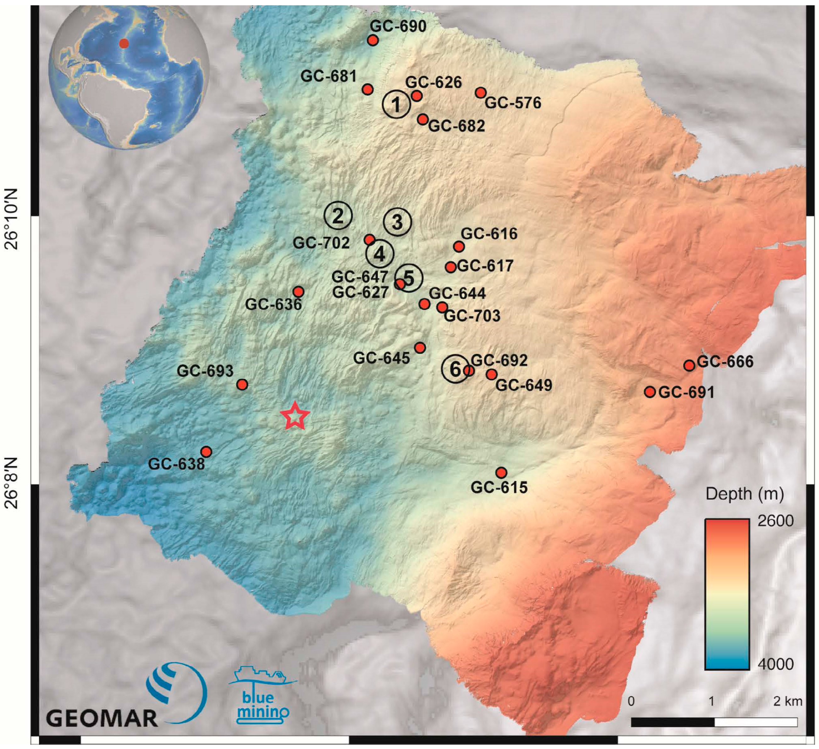
Figure 1. Location of gravity cores (GCs) recovered during M127 at the TAG hydrothermal field. Autonomous underwater vehicle (AUV) bathymetry map (2 m resolution) produced by GEOMAR (Helmholtz-Center for Ocean Research, Kiel, Germany) [14]. 1—Shimmering mound; 2—Shinkai mound; 3—Double mound 4—Southern mound; 5—Central area; 6—MIR zone; Red star-TAG active mound.
Minerals 10 00160 g001
Figure 2. XRD patterns of CS-A before ((a) original and (b) intensity-scale zoom) and (c) after treatment with acetate buffer. (For mineral name abbreviations and d-spacing labeled as a plane direction of h k l, see Table 2).
Minerals 10 00160 g002
Figure 3. Whole XRD patterns of carbonated samples (a) GC-627-B-151, (b) GC-690-CC and (c) GC-681-B-190 before (upper) and after (lower) treatment with acetate buffer. (For mineral name abbreviations and d-spacing labelled as a plane direction of h k l see Table 2).
Minerals 10 00160 g003
Figure 4. Relationship between the XRD intensity of the main (104) calcite peak (Iorig) and the sediment lightness (L*).
Minerals 10 00160 g004
Figure 5. Image of the GC-627 sections (C, B, A) with sampling points (white circles).
Minerals 10 00160 g005
Figure 6. XRD patterns of sediment samples selected from GC-627: (a) C-118, (b) B-175 and (c) A-226. (For mineral name abbreviations and d-spacing labeled as a plane direction of h k l, see Table 2).
Minerals 10 00160 g006
Figure 7. Image of the sediment core GC-702 with sampling points (white circles).
Minerals 10 00160 g007
Figure 8. XRD patterns of GC-702 sediment samples: (a) A-20, (b) A-30 and (c) A-53. (For mineral name abbreviations and d-spacing labeled as a plane direction of h k l, see Table 2).
Minerals 10 00160 g008
Figure 9. Image of sediment core GC-626 with sampling points in coarse-grained manganiferous core sections (white circles).
Minerals 10 00160 g009
Figure 10. XRD pattern of sample GC-626/A-75. (For mineral name abbreviations and d-spacing labeled as a plane direction of h k l, see Table 2).
Minerals 10 00160 g010
Table 1. Description and main physicochemical properties of M127 Gravity Cored (GC) sediment samples such as pH and Eh (min–max value).
GCWater
Depth (m)
Core
Length (cm)
pHEh (mV)No. of SamplesGeneral Description
57634341167.42–7.59222–3035Carbonate ooze; basalt fragments in the core catcher
61535551087.56–7.65149–2252Carbonate ooze with 2 shelly layers
6163500131nana1 #Carbonate ooze overlying brown to red silty-sandy layers with a few grey volcanic layers
6173462647.58–7.63195–2105 #Carbonate ooze
62634071207.29–7.36166–2264 #Carbonate ooze overlying brown to red silty-sandy sediments and basalt fragments; several Mn oxide breccia layers
62735193137.19–7.60−244–23520 #Repeating series of brown-red-orange silty-sandy sediment layers with several sulfide sand layers; dark layers of Mn oxides
63636041087.752001Carbonate ooze
638375320nana1 #Carbonate ooze
64435152697.42–7.73172–22315Repeating series of brown-red gravel and silty-sandy sediment layers and red-green patchy layers; several Mn oxide breccia layers
64535621317.712221Carbonate ooze with a 15 cm reddish silt layer
64735203007.31–7.73−195–21512Repeating series of brown-red-orange silty-sandy sediment beds with a few thin layers with fine sulfides and Mn oxides
64934231787.68–7.75176–1863 #Carbonate ooze overlying brown to red silty-sandy sediments with a few grey volcanic layers
6663000377.881711 #Carbonate ooze
68135103007.65–8.0158–3128 #Carbonate ooze overlying repeating series of brown-red silty-sandy-gravely sediment layers; Mn and Fe oxide breccia layers
68234452817.03–7.91−72–3399 #Carbonate ooze overlying repeating series of brown-red silty-sandy-gravely sediment and patchy layers; Mn and Fe oxide breccia layers
6903644807.851801 #Carbonate ooze
691306766nana1 #Carbonate ooze
6923422797.71–8.15151–1874 #Carbonate ooze overlying patchy red-brown-green gravel layers with Mn and Fe oxides
693365471nana4Mn oxide breccia interlaid with orange silt layers
7023560926.31–6.74−101–−23Brown silty-sandy sediment with fine grained sulfide layers
70334603007.14–7.69125–2346Carbonate ooze overlying dark heterogeneous layers of Mn and Fe oxide breccia
#—the lowermost sample from this core is from the core catcher; na—not analyzed or too coarse to be measured.
Table 2. Identified mineral phases in the analyzed TAG-sediment samples.
MineralAbbreviation *2θ (°)h k lFormulaRelative Content #
AlbiteAlb 27.88
22.03
0 0 2
−2 0 1
NaAlSi3O81–5
AnorthiteAn27.34
31.64
−2 2 0
132
CaAl2Si2O85–10
AragoniteArg 26.231 1 1CaCO31–5
AugiteAug 29.86−2 2 1(Ca,Mg,Fe)2Si2O61–5
BirnessiteBrn ** 12.490 0 1(NaCaK)0.6Mn2O4·1.5H2O1–5
CalciteCal 29.42
39.43
1 0 4
1 1 3
CaCO340–45
ChalcopyriteCcp 29.40
49.06
57.87
1 1 2
204
3 1 2
CuFeS215–20
ClinochloreClc7.11
12.43
0 0 2
0 0 2
Mg5Al(AlSi3O10)(OH)81–5
CovelliteCv 31.871 0 3CuS1–5
ForsteriteFo 36.501 1 2Mg2SiO41–5
GoethiteGt21.271 0 1FeO(OH)55–60
HematiteHem33.20
54.15
1 0 4
1 1 6
Fe2O35–10
IlliteIlt 8.83
26.66
0 0 2
006
K,Na,Mg,Fe,Al,Si,O·H201–5
KaoliniteKln 12.370 0 2Al2Si2O5(OH)41–5
MagnetiteMag35.583 1 1Fe3O41–5
MontmorilloniteMnt 5.89
19.84
0 0 1
1 0 1
Na0.3(Al,Mg)2Si4O10(OH)2·H2O10–15
NontroniteNnt **9.21
19.80
0 0 1
1 0 0
Na0.3Fe2(Si,Al)4O10(OH)2·H2O20–25
OlivineOl36.451 1 2(Mg,Fe)2SiO41–5
ParatacamitePtc ** 16.270 2 1(Cu,Zn)2(OH)3Cl1–5
PyritePy 56.35
33.09
3 1 1
2 0 0
FeS220–25
QuartzQtz26.660 1 1SiO240–45
SaponiteSap 5.62
26.42
0 0 1
0 0 5
Na0.33Mg3(Al0.33Si3.67)O10(OH)21–5
SepioliteSep 7.36
26.66
1 1 0
0 8 0
(Mg,Fe)4Si6O15(OH)2·6H201–5
SphaleriteSp 28.661 1 1ZnS1–5
TodorokiteTod ** 9.081 0 0MnO·H2O1–5
* Abbreviation for names of rock-forming minerals [35]; ** International Mineralogical Association (IMA) abbreviations; # Relative content in all studied sediment samples (expressed as a range in %).