Article

Kaolinite-Magnesite or Kaolinite–Talc-Based Ceramics. Part II: Microstructure and the Final Properties Related Sintered Tapes

1
Laboratoire de Traitement et Mise en Forme des Polymères Fibreux, Faculté des Sciences, Université M’Hamed Bougara Boumerdes, Boumerdes 35000, Algeria
2
Institut de Recherche sur les Céramiques (IRCER, UMRCNRS 7315), ENSIL-ENSCI, Université de Limoges, CEC, 12 rue Atlantis, CEDEX, 87068 Limoges, France
*
Author to whom correspondence should be addressed.
Minerals 2020, 10(12), 1080; https://doi.org/10.3390/min10121080
Submission received: 28 October 2020 / Revised: 19 November 2020 / Accepted: 27 November 2020 / Published: 1 December 2020
(This article belongs to the Special Issue Prospecting, Processing and Evaluation of Mineral Raw Materials)

Abstract

:
In recent decades, talc and kaolinite have been widely used as raw materials for the ceramic industry. In this study, the final characteristics of kaolinitic clay mixed with 6 mass% of magnesite obtained in our previous work were compared with those obtained with mixtures of kaolin (kaolin BIP) and talc (as the source of magnesium oxide). However, different amounts of talc in the kaolin powder were studied, namely 10, 30, and 50 mass% of added talc (with respect to kaolin + talc). The tape casting process was used during this work in order to manufacture the green tapes in an aqueous system with 0.2 mass% of dispersant. Subsequently, the green tapes were heated to 1000 and 1100 °C with a dwelling time of 12 min. The green and sintering tapes were characterized using the following techniques: DTA/TG, X-ray diffraction, porosity, and flexural strength analyses. The results obtained from our previous work indicate that the specimen with 6 mass% of MgCO3 sintered at 1200 °C for 3 h exhibited the best performances, with high flexural strength and weak porosity value—117 MPa and 27%—respectively. As results from this study, the optimal mechanical and thermal properties of sintering tapes were obtained for the specimen with 10 mass% of added talc sintered at 1100 °C. Indeed, this specimen exhibited 50 MPa and 43% of stress to rupture and apparent porosity, respectively.

1. Introduction

Many traditional and advanced ceramic materials are made from clay (or clay mixed with other materials) [1,2,3,4]. Indeed, the mixture of two or more clays of different composition and texture to form a paste is performed to improve the workability and firing behavior in comparison to the behavior of each single clay. Additionally, the blending of sediments with different proportions of clay and non-clay particles and/or different clay minerals is commonly used to enhance the final properties of some ceramics [5,6]. However, kaolinite and talc are both phyllosilicate minerals which present considerable interest to produce several types of ceramic materials (traditional and advances ceramics) for having certain valuable properties [7,8,9,10,11]. The addition of talc has positive effects on ceramic—for example, it increases the mechanical and optical properties of the ceramic material and glazes [12,13,14].
Kaolinite has a 1:1 sheet structure with chemical formulae Al2Si2O5(OH)4 (39.8 mass% Al2O3, 46.38 mass% SiO2, and 13.9 mass% H2O). It is a layered clay mineral consisting of the pilling up of two sheets—one tetrahedral sheet of silica (SiO4) joined to one octahedral sheet of alumina (AlO6) [15,16,17,18]. Indeed, the morphology of kaolinite mineral is plate-like. Its crystal system is triclinic with a C1-based space group. According to literature [19], the unit cell structure of kaolinite is illustrated in Figure 1.
On the other hand, talc is a magnesium hydrosilicate with the theoretical formula 3MgO·4SiO2·H2O, corresponding to 63.35 mass% SiO2, 31.90 mass% MgO, and 4.75 mass% of chemically bound water (hydroxide) [20]. In contrast, other minerals can be associated with talc, such as, chlorites, mica, actinolite, feldspars, rutile, pyrrhotite, carbonates, pyrite, magnetite, and hematite [12]. The crystalline structure of talc has a 2:1 or TOT layer type with one octahedral (O) magnesium layer sandwiched between two tetrahedral silica layers (Figure 2) [21].
In our previous work [1,17], the effect of magnesite amount on the different properties of kaolinitic clay ceramics was studied. However, in this study, we aimed to compare the final characteristics of the kaolinitic clay from Algeria (KT2) mixed with 6 mass% of magnesite, with those resulting from the use of a commercial kaolin (kaolin BIP) mixed with talc (as the source of magnesium oxide). Several mass contents of talc in the kaolin powder were investigated—10, 20, 30, 40, and 50 mass% of added talc. In a former paper, we suggested a firing temperature of up to 1200 °C, but the use of talc (melting of samples) did not allow performing heat treatments above 1100 °C. The structural changes (XRD, SEM), the mechanical, and thermal properties of the manufactured samples using tape casting were analyzed before and after sintering at 1000 and 1100 °C.

2. Materials and Methods

2.1. Raw Materials

In the present study, two kaolins were used: kaolinitic clay KT2 from Algeria (Tamazert, El Milia, Jijel, Algeria) and a commercial kaolin noted kaolin BIP the kaolin (Kaolin de Beauvoir, Imerys Limoges, France). The magnesite and the talc were provided by x and y, respectively. The chemical compositions of these raw materials are shown in Table 1. In this study, the kaolin KT2 was mixed with magnesite (KxMy), and kaolin BIP was mixed with talc (KxTy); in addition, T100 is 100% of talc.
Different organics additives were added to the mixture slurries, such as dispersant, binder, and plasticizer, which are dolaflux, polyvinyl alcohol (PVA 2200, VWR Prolabo, Geldenaaksebaan, Belgium), and polyethylene glycol (PEG 300, VWR, Prolabo, Germany), respectively.

2.2. Dispersions Preparation

Before dispersing of mixture slurries (kaolin/talc), 0.1 g·mL−1 dispersant solutions were prepared via dissolving of Dolaflux in a 3 M NaOH solution. The aqueous suspensions with 62.5 mass% of solid loading were dispersed with 0.1, 0.2, and 0.3 mass% of dispersant (respect to the clay content). The kaolinitic clay KT2 with and without 6 mass% of magnesite was consider in this paper. Nevertheless, different talc amounts were added to the kaolin suspension, namely, 10, 20, 30, 40, and 50 mass%. At the same time, all suspensions were mixed using a roll mixer for 24 h at room temperature in order to promote interactions between the clay particles and additives while removing residual air bubbles. The dispersion and formulation optimization have been already described in our former paper (part I.) [17].
After the dispersion step for the kaolin BIP and talc mixtures, the organic additives such as binder and plasticizer were added to these suspensions, polyvinyl alcohol (PVA 2200) and polyethylene glycol (PEG 300), respectively, which was ground in a planetary mill for 16 h at 100 rpm. The relative mass ratio between binder and plasticizer was equal to 1 in this study. However, a solution of 0.16 g·mL−1 binder was prepared by incorporating PVA slowly in deionized water, which was previously heated at 80 °C. During the addition of PVA, the solution was continuously stirred in order to avoid the formation of a gel. Prior to the tape casting, the slurries were de-aired on rollers for 22 h and sieved at 100 μm to ensure the elimination of the non-dissolved binder or impurities.

2.3. Preparation of Green and Sintered Bodies

Different slurries were cast under 10 mm/s of speed with a gap of 1 mm (thickness) between the blade and the casting support. After drying, the samples were cut in pellet. Once the green tapes were dried at room temperature (12 h), specimens of 30 mm diameter (disks) were collected using a circular punch. These samples were sintered in an electric furnace at a heating rate of 5 °C/min up to 1000 °C, and 1100 °C, dwelling time of 12 min at the maximum temperature. A cooling rate of 5 °C/min was used to decrease to room temperature. Figure 3 illustrated the shape and color of kaolin–talc-based tapes after sintering at 1000 and 1100 °C.

2.4. Characterization Techniques

2.4.1. Thermal Analysis

Differential thermal and gravimetric analyses (DTA/DTG) were measured using SETSYS 2400 DTA-TGA equipment from SETARAM (Caluire, France). The analysis was carried out under the temperature range 25–1300 °C at a heating rate of 5 °C/min using dried-air atmosphere (for all experiments, Pt crucibles were used). The thermal behavior helped to determine the most appropriate thermal cycle during sintering in order to avoid crack formation within sintered products.

2.4.2. Apparent Porosity

During this study, the apparent porosity of green and sintered specimens (ISO 11272:2017) was calculated using equation (Equation (1)). However, the bulk density (ρbulk) was determined from weight and dimensional measurements; apparent density (ρapparent) was estimated using a Micromeritics AccuPyc II 1340 helium-pycnometer (Norccross, GA, USA).
P = ( 1 ρ bulk ρ apparent )

2.4.3. X-Ray Diffraction

X-ray diffraction measurement of the samples was performed using a Bruker D5000 X-ray powder diffractometer (Bruker, Karlsruhe, Germany) equipped with a crystal monochromator (Cu-Kα radiation equal to 1.5406 Å) at room temperature. The measurements were achieved at 40 kV and 30 mA in a 2θ range from 2° to 70°, with a 2θ scanning rate of 0.5°/min and a step of 0.02°.

2.4.4. Scanning Electron Microscopy

In order to observe the microstructure of the samples, scanning electron microscope (SEM) observations (Stereosacan Cambridge S260 SEM microscope, Oxford Instruments, Abingdon, UK), were performed on the bottom and upper faces as well as on the sides of tapes. To prepare samples, the upper and bottom faces of specimens were set on carbon adhesive patches to stick to the sample holder. Fractures of tapes were set vertically on carbon paste to observe slices. Silver lacquer was evenly applied on sample surfaces. In all cases, a 15 mm gold layer was deposited in order to improve the electrical conduction at the surface of samples (to improve the quality of the images).

2.4.5. Biaxial Flexural Strength

The mechanical properties of each green and sintered tape with different talc amounts were assessed by the measurement of the biaxial flexural strength through universal machine Lloyd Easy Test EZ 20 (Largo, FL, USA) equipped with a piston-ring configuration. The crosshead velocity and the preload were fixed at 1 mm∙min−1, 0.2 N, respectively. A high sensitivity sensor (100 N) was chosen because load submitted to specimens has to represent at least 1% of the maximum range. Samples used for biaxial bending tests were shaped as 30 mm in diameter disks.
For the piston on the three ball test, the modified Kirstein and Woolley’s [22] equation for the maximum biaxial flexure strength (in MPa) was:
σ R = 3 P R ( 1 + ν ) 4 π e 2   ( 1 + 2 × l n A B + ( 1 ν 1 + ν ) × ( 1 B 2 2 A 2 ) × A 2 C 2 )
In this formula, PR is the ultimate sustained load, A is the diameter of the ring equal to 28 mm of the support ring, B is diameter of the upper piston equal to 5 mm, C is the specimen diameter (mm), e is the specimen thickness (mm), and ν is Poisson’s ratio (0.25). For all tested specimens, diameter (C) was voluntarily chosen as 30 mm. For each set of specimens, 5 values of stress to rupture were measured, and the results presented are the mean values of each series of 5 measurements.

3. Results and Discussion

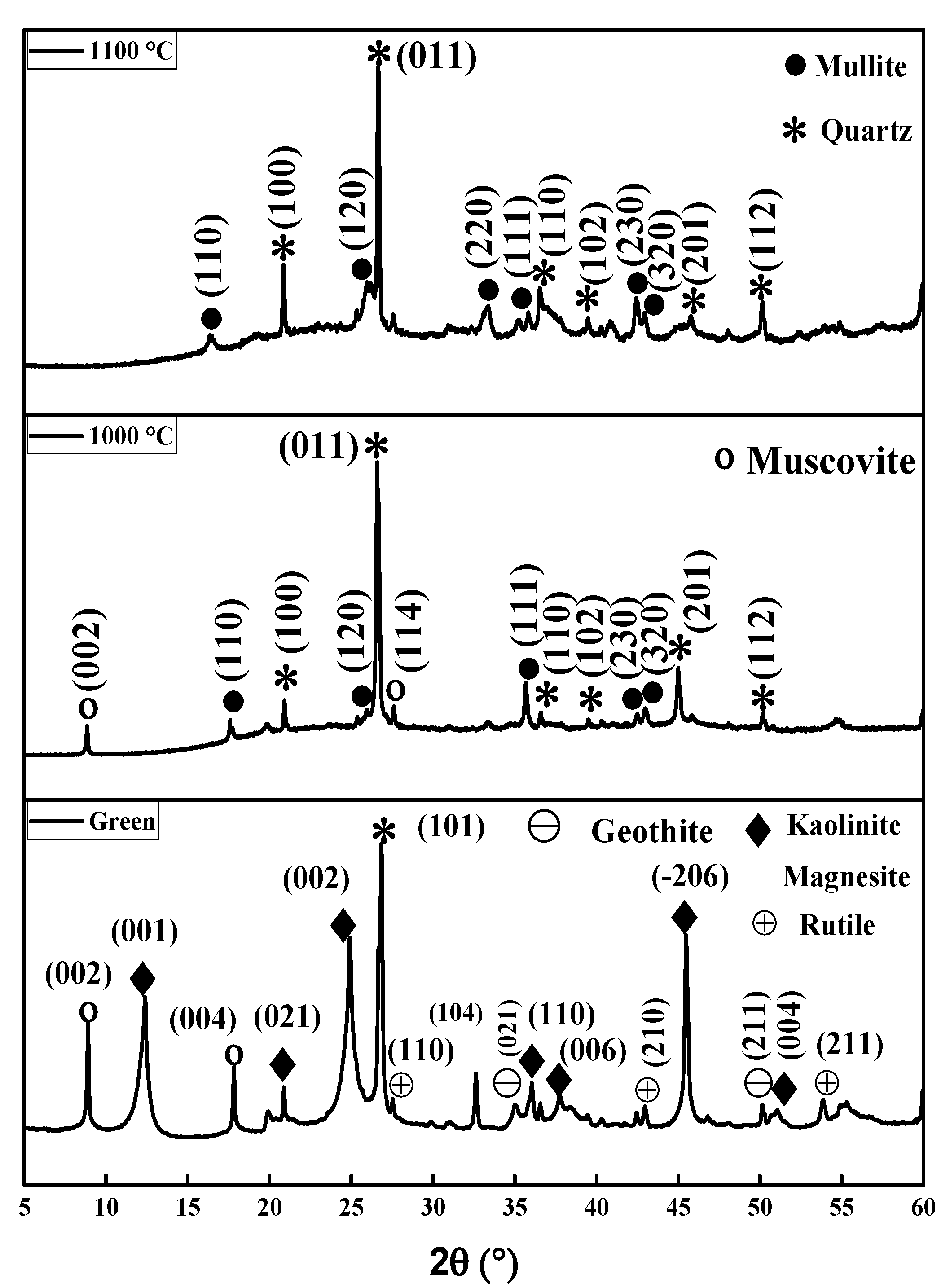
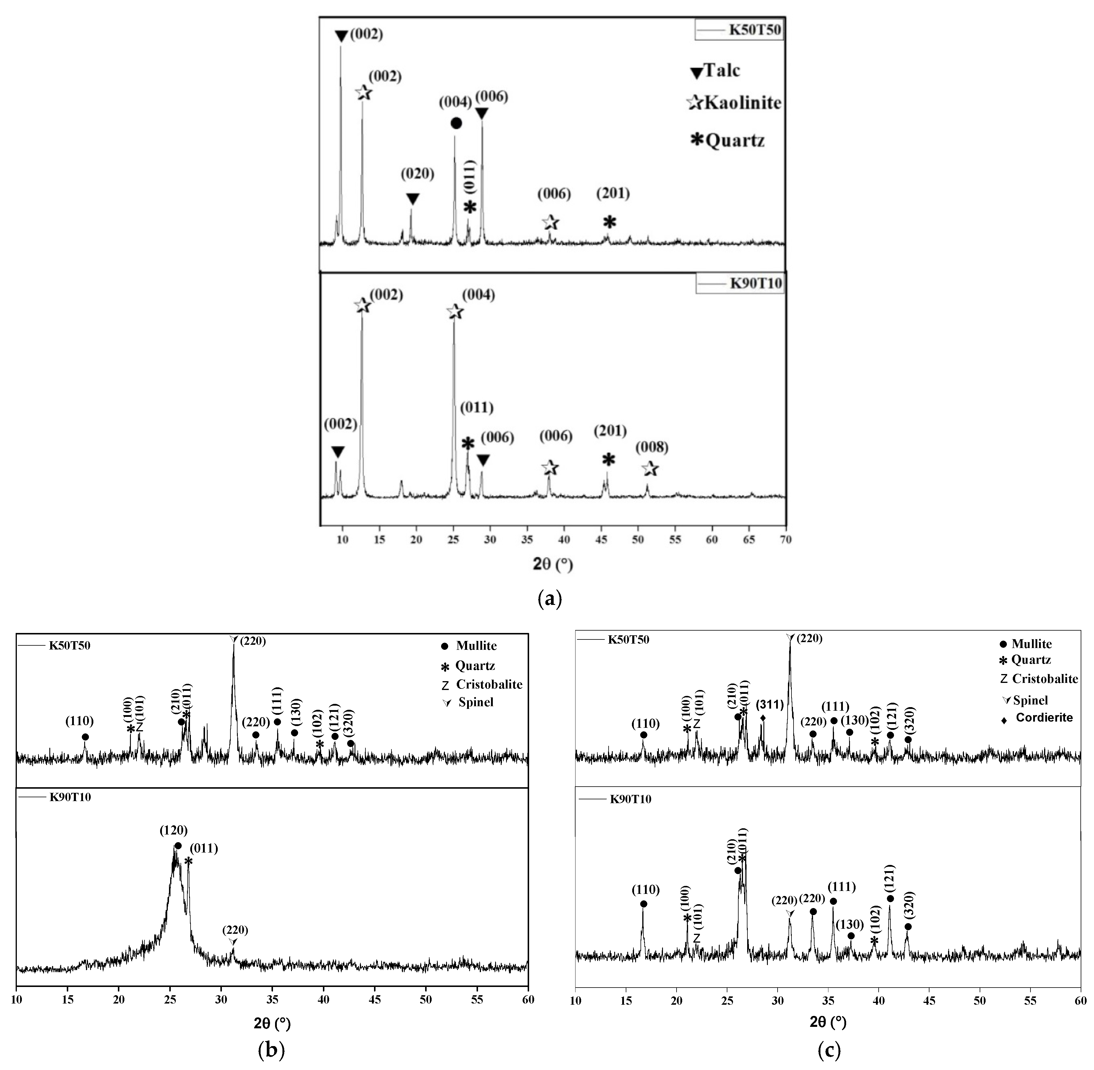
3.1. XRD, Thermal Behavior and Microstructure of Green and Sintered Specimens

In order to the determine DTA and TG curves for the different Mg-enriched kaolin samples, the final properties of samples after sintering at 1000 and 1100 °C were characterized. The typical behavior of the prepared tapes are presented on Figure 4. Indeed, four main transformations were observed in all our samples, namely:
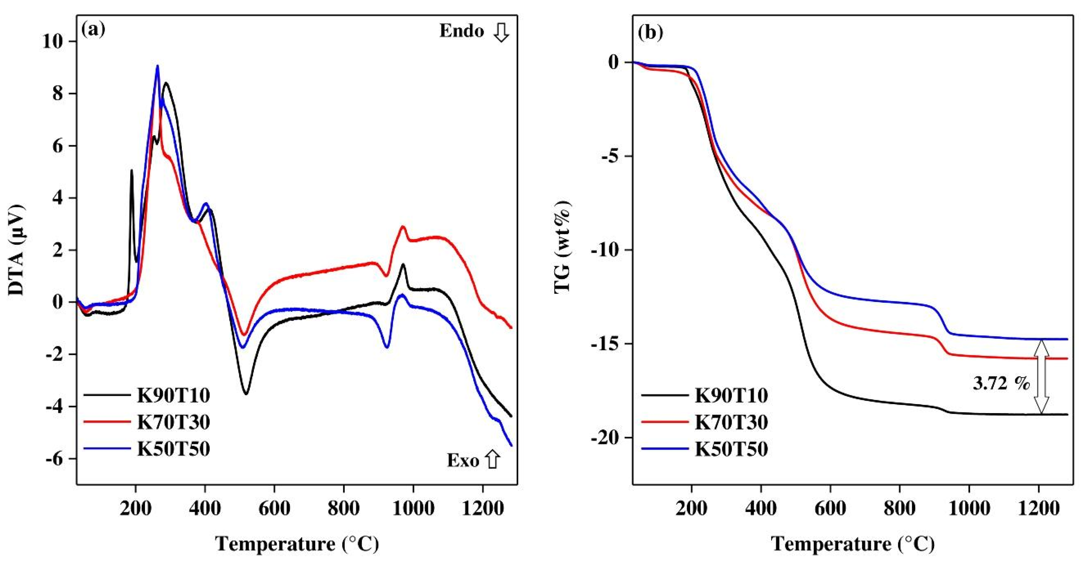
  • The dehydration of the green tapes in the region between 70 and 120 °C (endothermic peak);
  • The burning of organics used as binders and plasticizer in the range 150 to 400 °C (consecutive exothermic peaks associated with significant mass loss);
  • The dehydroxylation of kaolinite between 400 and 650 °C, characterized by an endothermic peak which appeared proportional to the kaolin content in the mixture (also the related mass loss);
  • The dehydroxylation of talc in the range 850 to 1000 °C, characterized by an endothermic peak (proportional to the talc content as the mass loss) very close to the exothermic peak associated to the structural reorganization of the metakaolinite.
Considering these thermal analyses results, it appeared that above 1100 °C, an important melting occurred within our kaolin–talc tapes; thus, it was decided to conduct the heat treatments at 1000 and 1100 °C in line with the characterization of apparent porosity and flexural strength.
First, the crystalline phase of green and sintered tapes were analyzed using XRD measurements. The obtained XRD patterns are presented on Figure 5 and Figure 6.
For the samples K94M6, the main crystallized phases appeared to be few quartz (JCPDS 01-070-7344) and mullite (JCPDS 00-015-0776). Cordierite phase (JCPDS 00-012-0303) seemed to be present through the very small diffraction peak located at 15° and 29.7° (2θ). The reaction sequence could be summarized regarding the Equations (3)–(7), with Equations (3) and (4) for the formation of primary and secondary mullite, and Equations (5) and (7) for the crystallization of cordierite [23,24,25]. Equation (5) characterized the decarbonation of magnesite prior to its reaction with alumina to form a spinel phase. Note that the competition between the crystallization of mullite and the formation of cordierite tended to be profitable to mullite until temperature close to 1200 °C.
2(Al2Si2O5) → 2Al2O3·3SiO2 + SiO2 (amorphous)
3(Al2Si2O5) → 2(3Al2O3·2SiO2) + 5 SiO2 (amorphous)
MgCO3 → MgO + CO2
2(MgO·Al2O3) + 5(SiO2) → (2MgO·2Al2O3·5SiO2)
5(3Al2O3·2SiO2) + 15 MgO → 2(2MgO·2Al2O3·SiO2) + 11(MgO·Al2O3)
In the case of kaolin–talc mixtures, we detected the presence of spinel and cristobalite (due to the structural reorganization of metakaolinite) after sintering at 1000 °C. In addition, the sintering of these samples at 1100 °C tended to enhance the crystallization of mullite (JCPDS 00-015-0776) and the formation of cordierite (JCPDS 00-012-0303) as expected. The observation of their microstructure by SEM (Figure 7) showed a significant change in the shape of the clay platelets, which appeared with rounded corners due the formation of transitory liquid phases in agreement with the ternary phase diagram SiO2-Al2O3-MgO.

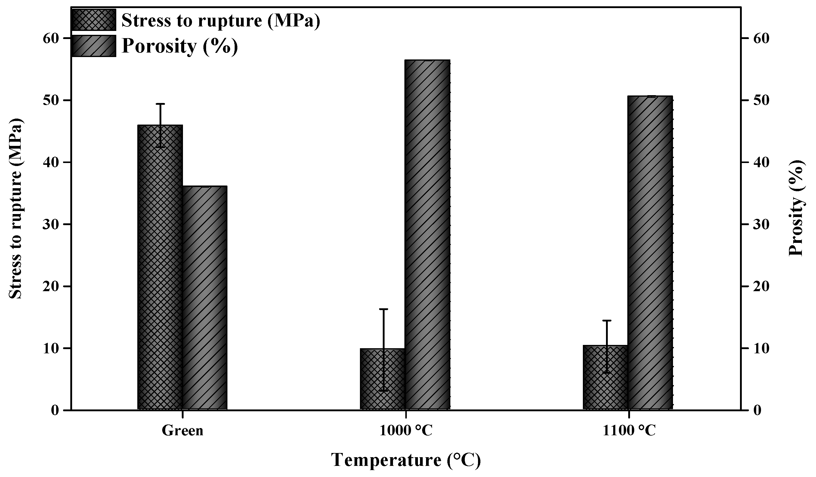
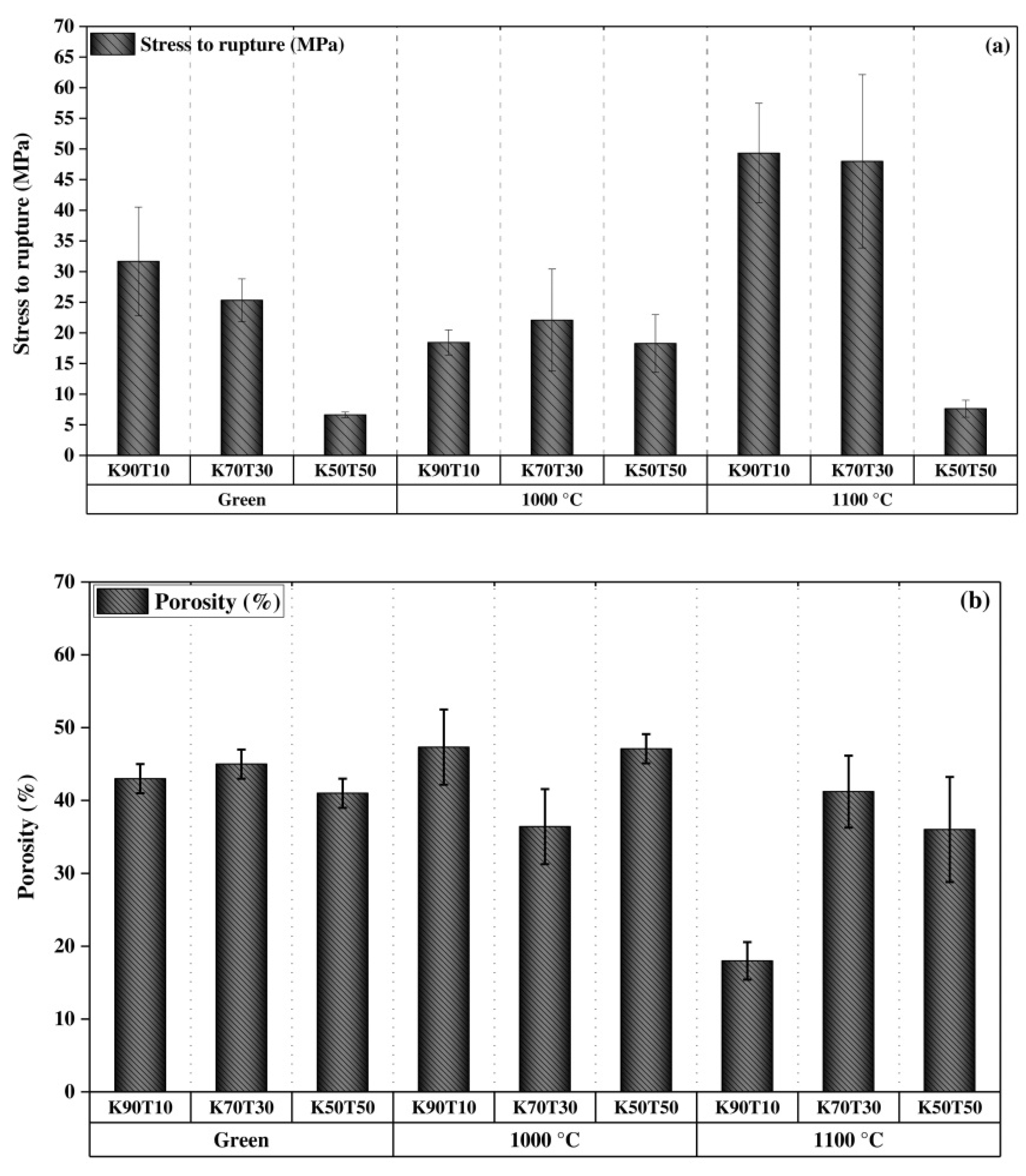
3.2. Mechanical Properties and Porosity

After sintering of the various specimens, the obtained biaxial flexural strength and apparent porosity are presented in Figure 8 and Figure 9. In the green tapes, the addition of talc to kaolin tended to decrease the stress to rupture, while the apparent porosity was close to 40% in all cases (see Figure 9b). A similar trend was observed with the sample KT2M6 compared to KT2. This behavior seemed to be related to the higher plasticity of the kaolin used in this study compared to the talc material or to the magnesite. However, according to our previous study [1], it was indicated that the mechanical properties of K94M6 tapes were strongly affected by their microstructure, and as a result, biaxial flexural strength increased when porosity decreased [26]. Consequently, it appears in Figure 8 that the stress to rupture values decreased while sintering at 1000 or 1100 °C. Moreover, the decarbonation of magnesite contributed to increasing the apparent porosity of K94M6 samples after sintering up to 1100 °C, thus to observed decrease the biaxial flexural strength down to 10 MPa.
Upon sintering at 1000 °C, the sample K70T30 exhibited the best stress to rupture (20 MPa) compared to the other samples sintered at the same temperature. The latter samples exhibited higher apparent porosity, justifying the observed behavior. Moreover, for the sample containing magnesite (K94M6), the level of apparent porosity was higher due to the decarbonation during sintering that significantly contributed to increasing the remaining porosity [17,27]. Sintering at 1000 °C tended to promote the decrease in viscosity of the amorphous phase (Arrhenius type dependence of viscosity with temperature), and therefore, promoted the initiation of viscous flow sintering of the studied samples. Consequently, an increase in the stress to rupture and a decrease in the apparent porosity were noted for most specimens. K50T50 samples despite very a low decrease in their apparent porosity exhibited the lowest stress to rupture values.
The observation of the microstructure of K50T50 samples regarding the top surface (upper side) and bottom surface (in contact with the tape carrier) allowed observing a significant heterogeneous distribution of pores, grains and amorphous phase within these samples (Figure 10). It seemed likely that the sintering did not progress uniformly in the considered samples and could explain the lower mechanical resistance collected for K50T50. In the case of the K94M6, it a high apparent porosity (close to 50%) was observed in agreement with the low stress to rupture. Such trend seemed consistent with the importance of the source of magnesium while using mixtures with kaolin in order to promote the formation of cordierite and enhance the properties of use. Indeed, it was necessary to perform the sintering of kaolin-magnesite mixture at a higher temperature (1200 °C) in order to obtain equivalent properties of use obtained while using kaolin–talc mixtures. Moreover, the use of 10 to 30 mass % of talc in kaolin–talc mixtures allowed the enhancement of the stress to rupture and apparent porosity after sintering at only 1100 °C.

4. Conclusions

The present study aimed to characterize the final properties of kaolin–talc mixtures (10 to 50 mass% of talc) shaped by tape casting comparatively to those of K94M6 (kaolin-magnesite mixture with 6 mass% of magnesite) obtained in a previous study in order to understand the effect of magnesium source regarding such cordierite-mullite ceramics.
The starting mixtures were prepared as indicated in part I of this paper, namely optimization of slurries dispersion and stability. A 0.2 mass% of dolaflux B was used as the dispersant for kaolin–talc mixtures. The sintering of samples at 1000 °C led to porous and weak products (low stress to rupture values) compared to a sintering at 1100 °C. Moreover, compared to the K94M6 sample, the apparent porosity of kaolin–talc mixtures was lowered, while their stress to rupture was increased after sintering at 1100 °C. The XRD analyses of these samples indicated the presence of quartz and mullite within K94M6 tapes. In addition, mullite, quartz and cordierite (with well-defined peaks) appeared in kaolin–talc mixtures. The microstructure of K50T50 (kaolin with 50 mass% of talc) after firing at 1100 °C exhibited heterogeneous densification and distribution of pores and amorphous phase.
The results highlighted the interesting properties obtained while using a phyllosilicate such as talc as a magnesium source to produce mullite-cordierite ceramics at alower temperature with enhanced densification and mechanical properties. Nevertheless, investigations should continue regarding the influence of the heating cycle (heating rate and soaking time), the purity of kaolin and talc materials and the related thermal properties.

Author Contributions

Conceptualization, F.Z. and G.L.-N.; methodology, F.Z. and G.L.-N.; software, A.H., I.D.; validation, G.L.-N. and F.Z.; formal analysis, A.H. and G.L.-N.; investigation, A.H., I.D., N.T.-D.; resources, C.P., G.L.-N. and F.Z.; data curation, A.H., I.D., and G.L.-N.; writing—original draft preparation, A.H. and G.L.-N.; writing—review and editing, A.H. and G.L.-N.; visualization, G.L.-N.; supervision, F.Z. and G.L.-N.; project administration, F.Z., G.L.-N., N.T.-D. and C.P.; funding acquisition, F.Z. All authors have read and agreed to the published version of the manuscript.

Funding

This research received no external funding.

Conflicts of Interest

The authors declare no conflict of interest.

References

  1. Hammas, A.; Lecomte-Nana, G.; Daou, I.; Zibouche, F. Sintering and final properties of kaolinite-magnesite tapes for the manufacture of cordierite-mullite ceramics. Int. J. Appl. Ceram. Technol. 2020, 17, 2265–2276. [Google Scholar] [CrossRef]
  2. Corni, I.; Ryan, M.P.; Boccaccini, A.R. Electrophoretic deposition: From traditional ceramics to nanotechnology. J. Eur. Ceram. Soc. 2008, 28, 1353–1367. [Google Scholar] [CrossRef]
  3. Ten, J.G.; Orts, M.J.; Saburit, A.; Silva, G. Thermal conductivity of traditional ceramics. Part I: Influence of bulk density and firing temperature. Ceram. Int. 2010, 36, 1951–1959. [Google Scholar]
  4. Manfredini, T.; Hanuskova, M. Natural raw materials in “Traditional” ceramic manufacturing. J. Univ. Chem. Technol. Metall. 2012, 47, 465–470. [Google Scholar]
  5. Tarvornpanich, T.; Souza, G.P.; Lee, W.E. Microstructural Evolution in Clay-Based Ceramics II: Ternary and Quaternary Mixtures of Clay, Flux, and Quartz Filler. J. Am. Ceram. Soc. 2008, 91, 2272–2280. [Google Scholar] [CrossRef]
  6. Pontikes, Y.; Nikolopoulos, P.; Angelopoulos, G.N. Thermal behaviour of clay mixtures with bauxite residue for the production of heavy-clay ceramics. J. Eur. Ceram. Soc. 2007, 27, 1645–1649. [Google Scholar] [CrossRef]
  7. Zbik, M.; Smart, R.S.C. Influence of dry grinding on talc and kaolinite morphology: Inhibition of nano-bubble formation and improved dispersion. Miner. Eng. 2005, 18, 969–976. [Google Scholar] [CrossRef]
  8. de Brito, I.P.; de Almeida, E.P.; de Araújo Neves, G.; de Lucena Lira, H.; Menezes, R.R.; da Silva, V.J.; de Lima Santana, L.N. Development of cordierite/mullite composites using industrial wastes. Int. J. Appl. Ceram. Technol. 2020. [Google Scholar] [CrossRef]
  9. Naga, S.M.; Sayed, M.; El-Omla, M.M.; Wassel, A.R.; El-Mehalawy, N. Processing of electric ceramic insulators from slate rocks and MgO. Mater. Manuf. Process. 2020, 35, 893–900. [Google Scholar] [CrossRef]
  10. Sittiakkaranon, S. Thermal Shock Resistance of Mullite-Cordierite Ceramics from Kaolin, Talc and Alumina Raw Materials. Mater. Today Proc. 2019, 17, 1864–1871. [Google Scholar] [CrossRef]
  11. Lecomte-Nana, G.L.; Lebdioua, K.; Laffort, M.; Houta, N.; Tessier-Doyen, N.; Abouliatim, Y.; Peyratout, C. Effect of phyllosilicate type on the microstructure and properties of kaolin-based ceramic tapes. Ceram. Eng. Sci. Proc. 2017, 37, 47–601. [Google Scholar]
  12. Tufar, W. Talc. In Ullmann’s Encyclopedia of Industrial Chemistry; Wiley-VCH Verlag GmbH & Co. KGaA: Weinheim, Germany, 2000. [Google Scholar]
  13. Wattanasiriwech, S.; Wattanasiriwech, D. Roles of talc-illite on phase transformation, vitrification and physical properties of a triaxial porcelain body. J. Ceram. Process. Res. 2019, 20, 643–648. [Google Scholar] [CrossRef]
  14. Lao, X.; Xu, X.; Jiang, W.; Liang, J.; Miao, L.; Wu, Q. Influences of impurities and mineralogical structure of different kaolin minerals on thermal properties of cordierite ceramics for high-temperature thermal storage. Appl. Clay Sci. 2020, 187, 105485. [Google Scholar] [CrossRef]
  15. Chakraborty, A.K. Phase Transformation of Kaolinite Clay; Springer: New Delhi, India, 2014; ISBN 9788132211549. [Google Scholar]
  16. Scholtzová, E.; Tunega, D. Prediction of mechanical properties of grafted kaolinite—A DFT study. Appl. Clay Sci. 2020, 193, 105692. [Google Scholar] [CrossRef]
  17. Hammas, A.; Lecomte-Nana, G.; Azril, N.; Daou, I.; Peyratout, C.; Zibouche, F. Kaolinite-Magnesite Based Ceramics. Part I: Surface Charge and Rheological Properties Optimization of the Suspensions for the Processing of Cordierite-Mullite Tapes. Minerals 2019, 9, 757. [Google Scholar] [CrossRef] [Green Version]
  18. Tunega, D.; Zaoui, A. Mechanical and Bonding Behaviors Behind the Bending Mechanism of Kaolinite Clay Layers. J. Phys. Chem. C 2020, 124, 7432–7440. [Google Scholar] [CrossRef] [PubMed] [Green Version]
  19. Han, Y.; Liu, W.; Zhou, J.; Chen, J. Interactions between kaolinite AlOH surface and sodium hexametaphosphate. Appl. Surf. Sci. 2016, 387, 759–765. [Google Scholar] [CrossRef]
  20. Katircioglu-Bayel, D. Impact of Operating Parameters on the Breakage Process of Talc. Mining Metall. Explor. 2020, 37, 1717–1727. [Google Scholar] [CrossRef]
  21. Wang, H.; Sun, Y.; Chu, J.; Wang, X.; Zhang, M. Crystalline structure variation within phlogopite, muscovite and talc under 0–1000 kGy γ ray irradiation: A clear dependence on intrinsic characteristic. Appl. Clay Sci. 2020, 187, 105475. [Google Scholar] [CrossRef]
  22. Kirstein, A.F.; Woolley, R.M. Symmetrical bending of thin circular elastic plates on equally spaced point supports. J. Res. Natl. Bur. Stand. C 1967, 71, 1–10. [Google Scholar] [CrossRef]
  23. Chen, C.Y.; Lan, G.S.; Tuan, W.H. Microstructural evolution of mullite during the sintering of kaolin powder compacts. Ceram. Int. 2000, 26, 715–720. [Google Scholar] [CrossRef]
  24. Benhammou, A.; El Hafiane, Y.; Abourriche, A.; Abouliatim, Y.; Nibou, L.; Yaacoubi, A.; Tessier-Doyen, N.; Smith, A.; Tanouti, B. Influence of sintering temperature on the microstructural and mechanical properties of cordierite synthesized from andalusite and talc. Mater. Lett. 2016, 172, 198–201. [Google Scholar] [CrossRef]
  25. Souto, P.M.D.; Menezes, R.R.; Kiminami, R.H.G.A. Evaluation of the Influence of MgO and La2O3 on the Fast Sintering of Mullite. Mater. Res. 2015, 18, 42–53. [Google Scholar] [CrossRef]
  26. Zhu, Z.; Wei, Z.; Sun, W.; Hou, J.; He, B.; Dong, Y. Cost-effective utilization of mineral-based raw materials for preparation of porous mullite ceramic membranes via in-situ reaction method. Appl. Clay Sci. 2016, 120, 135–141. [Google Scholar] [CrossRef]
  27. Hurt, S.M.; Wolf, A.S. Anomalous structure of MgCO3 liquid and the buoyancy of carbonatite melts. Earth Planet. Sci. Lett. 2020, 531, 115927. [Google Scholar] [CrossRef]
Figure 1. Structure of kaolinite primitive cell (white, hydrogen; red oxygen; pink, aluminum; yellow, silicon) [19].
Minerals 10 01080 g001
Figure 2. Schematic representation of the talc structures.
Minerals 10 01080 g002
Figure 3. Samples after heat treatments at 1000 and 1100 °C (soaking time of 12 min).
Minerals 10 01080 g003
Figure 4. DTA (a) and TG (b) curves of three kaolin–talc tapes (under air up to 1200 °C), K50T50, K70T30, and K90T10.
Minerals 10 01080 g004
Figure 5. XRD patterns of K94M6 (green tapes and tapes sintered at 1000 and 1100 °C).
Minerals 10 01080 g005
Figure 6. XRD patterns of K90T10 and K50T50 tapes: (a) green samples, (b) samples sintered at 1000 °C, and (c) samples sintered at 1100 °C.
Minerals 10 01080 g006
Figure 7. Typical SEM images of the kaolin–talc tapes K90T10 before and after sintering at 1100 °C.
Minerals 10 01080 g007
Figure 8. Mechanical properties and apparent porosity of KT2- kaolin mixed with 6 mass% of magnesite.
Minerals 10 01080 g008
Figure 9. Comparative values of (a) the stress to rupture and (b) the apparent porosity of kaolin–talc tapes before and after sintering at 1000 and 1100 °C.
Minerals 10 01080 g009
Figure 10. SEM images of K50T50 tapes sintered at 1100 °C.
Minerals 10 01080 g010
Table 1. Chemical composition (XRF analyses) and other characteristic physical properties of the starting powders. LOI, loss on ignition at 1050 °C.
Raw MaterialSSA (BET) (±0.1 m2·g−1)Density (g·cm−3) Chemical Composition (mass%)
SiO2Al2O3MgOFe2O3TiO2Li2OCaONa2OK2OLOI
Kaolinitic clay KT225.02.647.832.90.63.50.5-0.10.12.911.5
Kaolin BIP11.72.648.139.90.170.26<0.250.27<0.2<0.21.910
Talc11.02.7630.230.51.4<0.1-0.250.030.014.7
Magnesite11.72.93.20.142.70.4--3.2--50.4
K94M6 45.030.93.13.30.4-0.30.12.713.8
K90T10 49.635.93.20.4<0.230.240.20.181.79.5
K80T20 51.131.96.20.5<0.20.220.20.161.58.9
K70T30 52.6289.30.6<0.170.20.20.141.38.4
K60T40 54.12412.30.7<0.150.160.20.121.147.9
K50T50 55.620.115.30.80.180.130.20.10.957.4
Publisher’s Note: MDPI stays neutral with regard to jurisdictional claims in published maps and institutional affiliations.

