
A Study on Big Data Thinking of the Internet of Things-Based Smart-Connected Car in Conjunction with Controller Area Network Bus and 4G-Long Term Evolution

Abstract
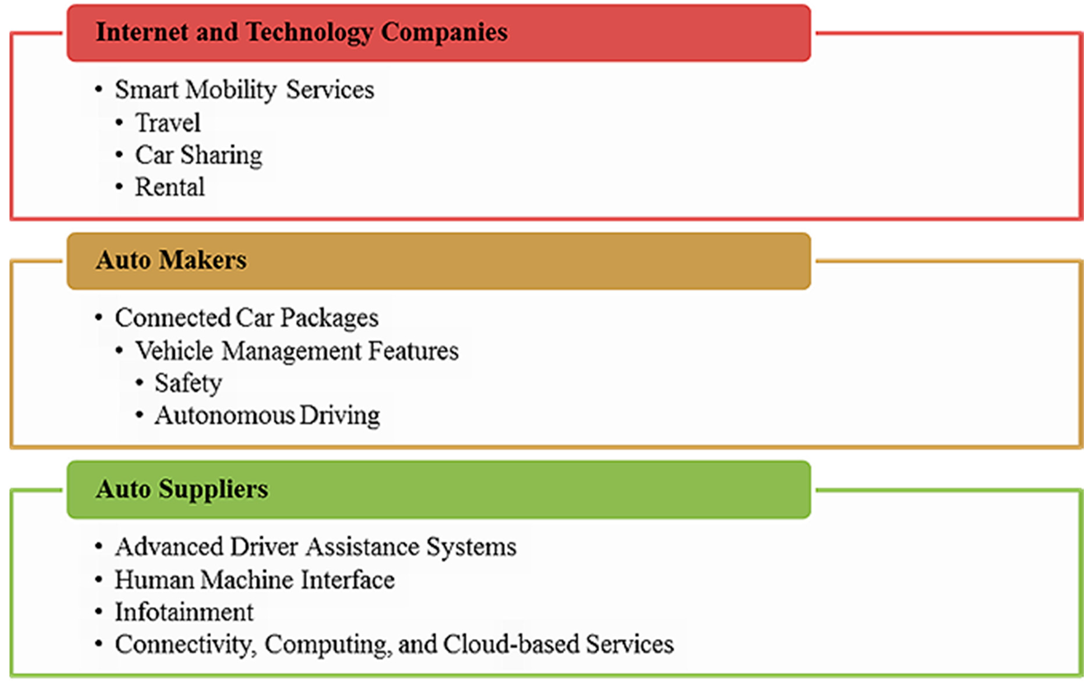
:1. Introduction
2. Related Work
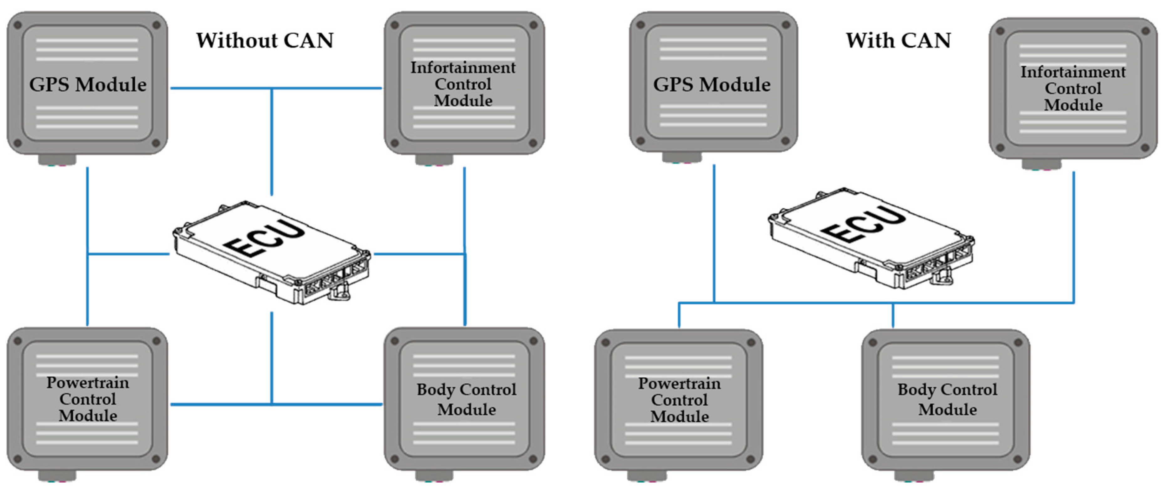
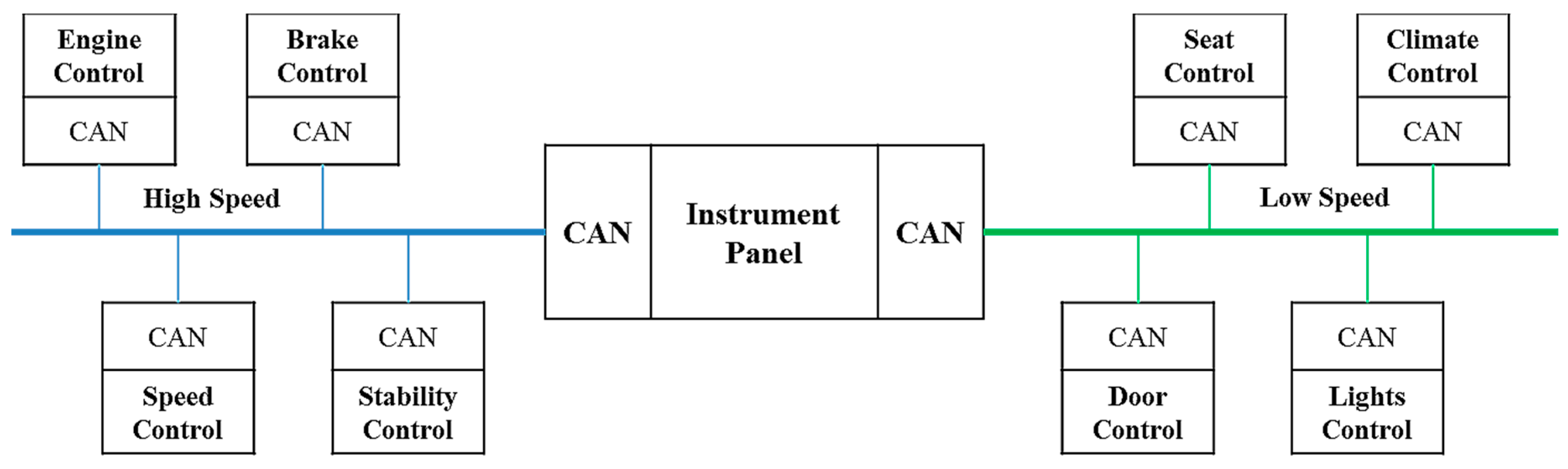
2.1. Controller Area Network Bus Network
2.2. The Overview of Vehicle-To-Vehicle
2.3. The Overview of Vehicle-To-Infrastructure
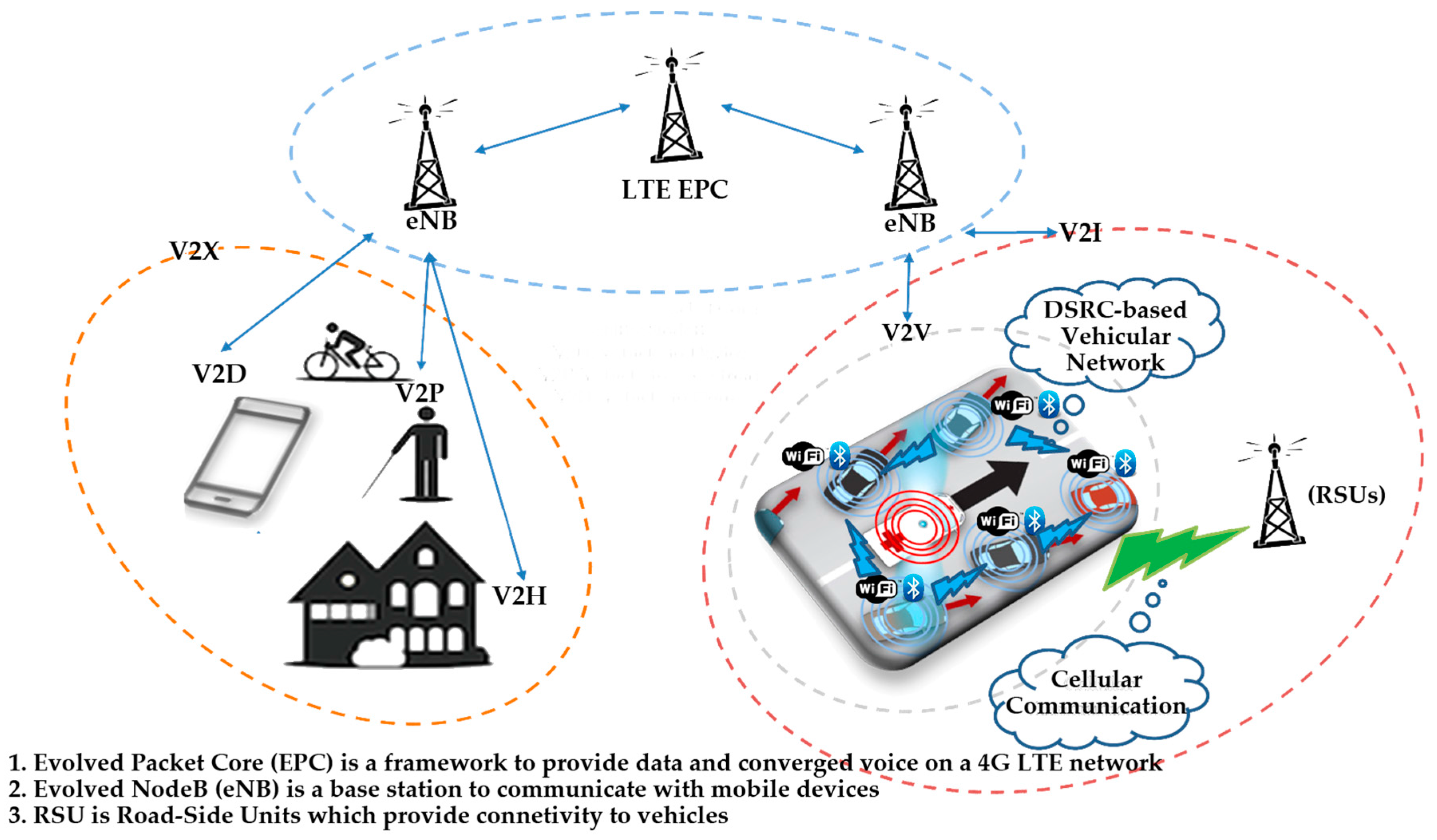
2.4. The Overview of Vehicle-To-Everything
2.5. The Overview of Connected Cars
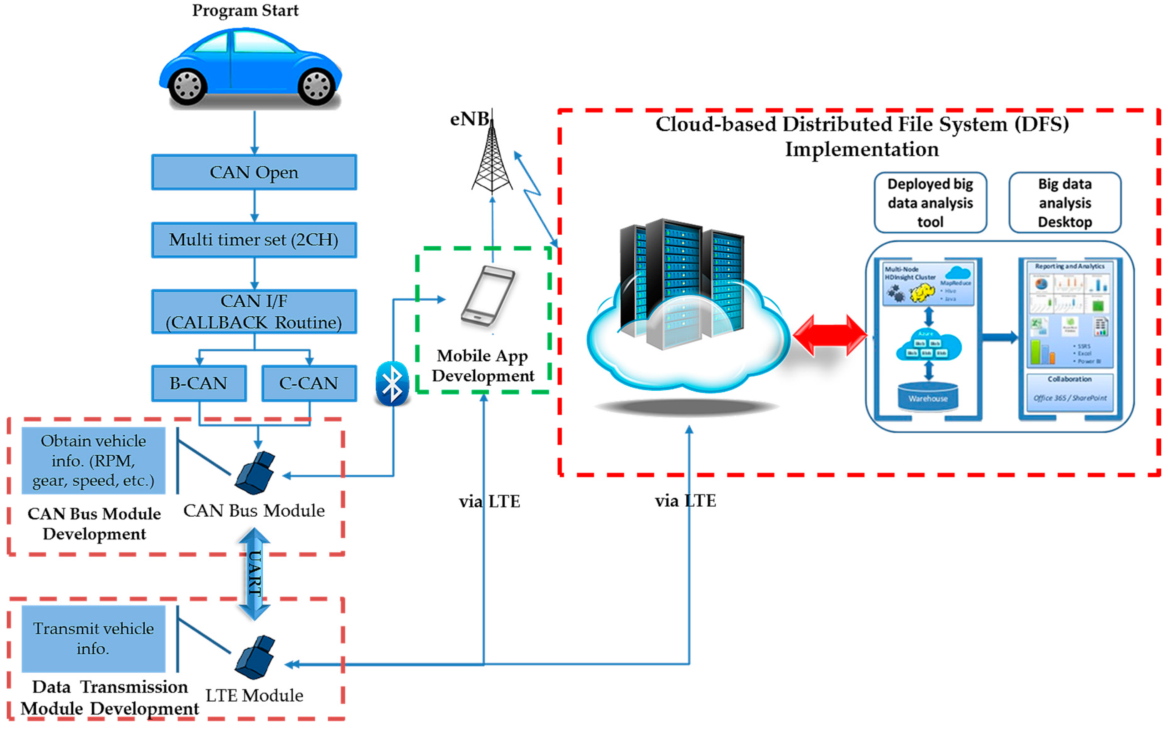
3. The Proposed Research Directions and System Architecture
- Although powertrain-related vehicle information, which is used for driving information, is a primary source for big data analysis, both B-CAN and C-CAN are adopted.
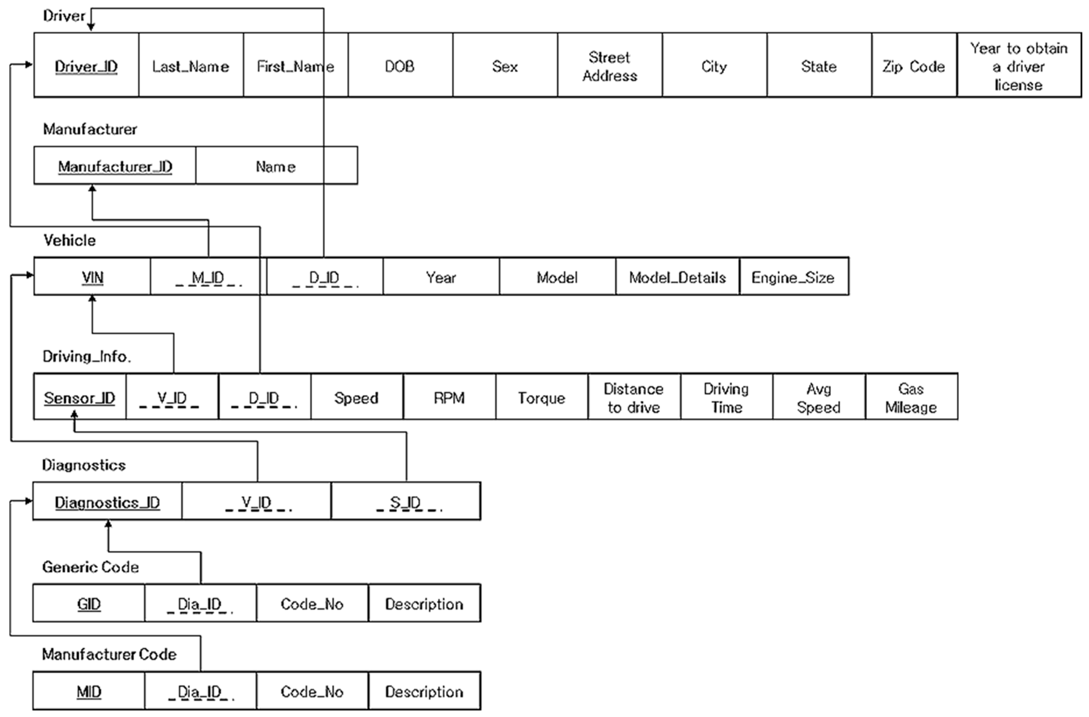
- DB, which is composed of a driver table, vehicle table, and diagnostics table, needs to be implemented.
- The diagnostics table stores each automaker’s diagnostic codes so that drivers are able to check vehicle malfunctions via a mobile application.
- DB should be designed by normalization so that data redundancy can be avoided.
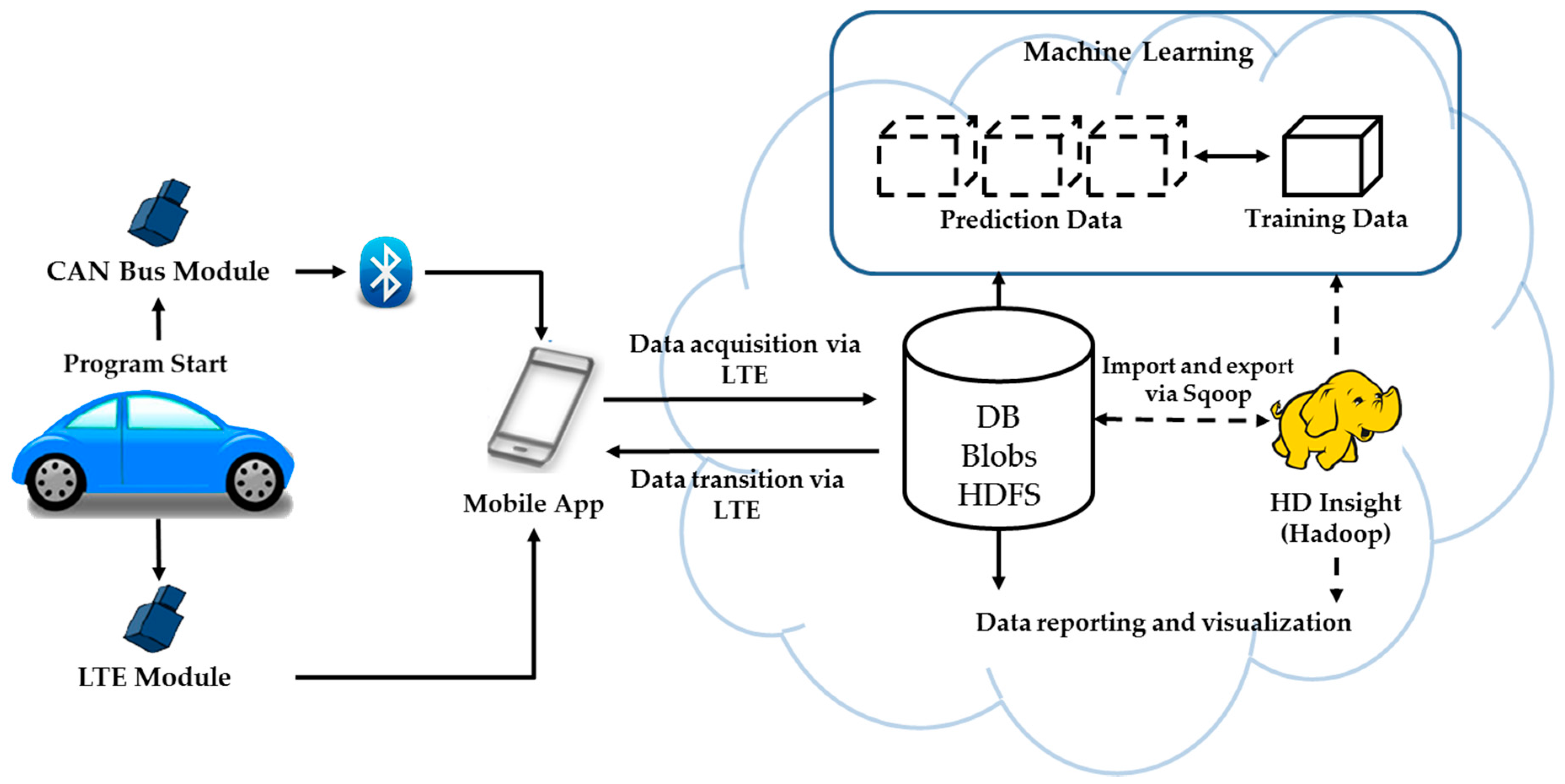
- Cloud-based DFS implementation is required for big data analysis.
- Since the IoT concept in this research refers to the V2I concept, which is also based on the V2V concept, short-range and long-range connectivity based on Bluetooth and 4G-LTE are employed as the main communication networks.
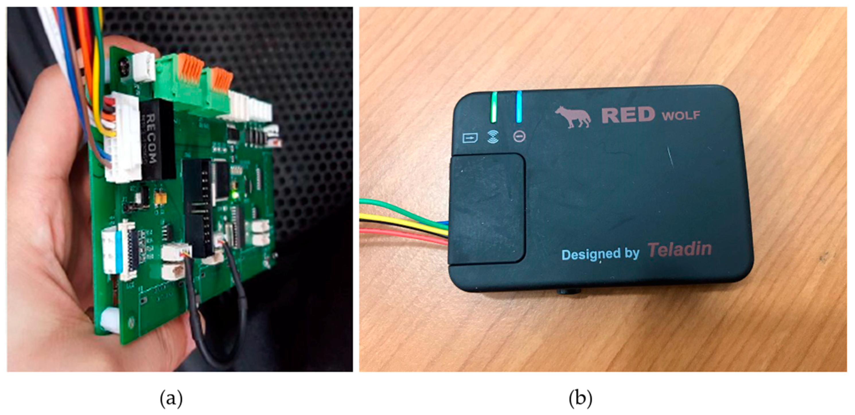
4. Proof of Actual Development and Proposing System Design
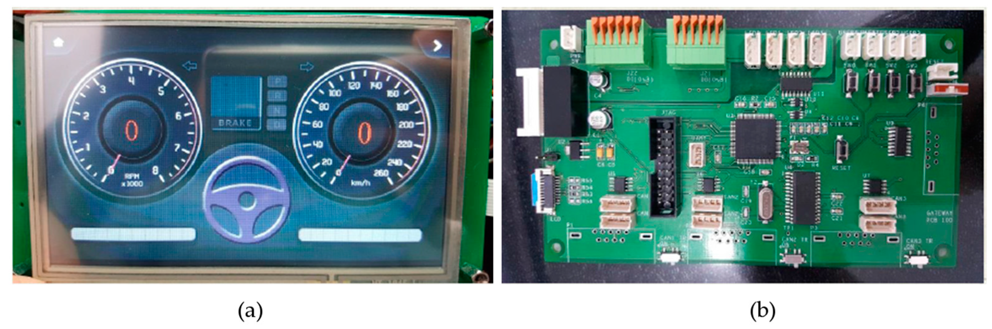
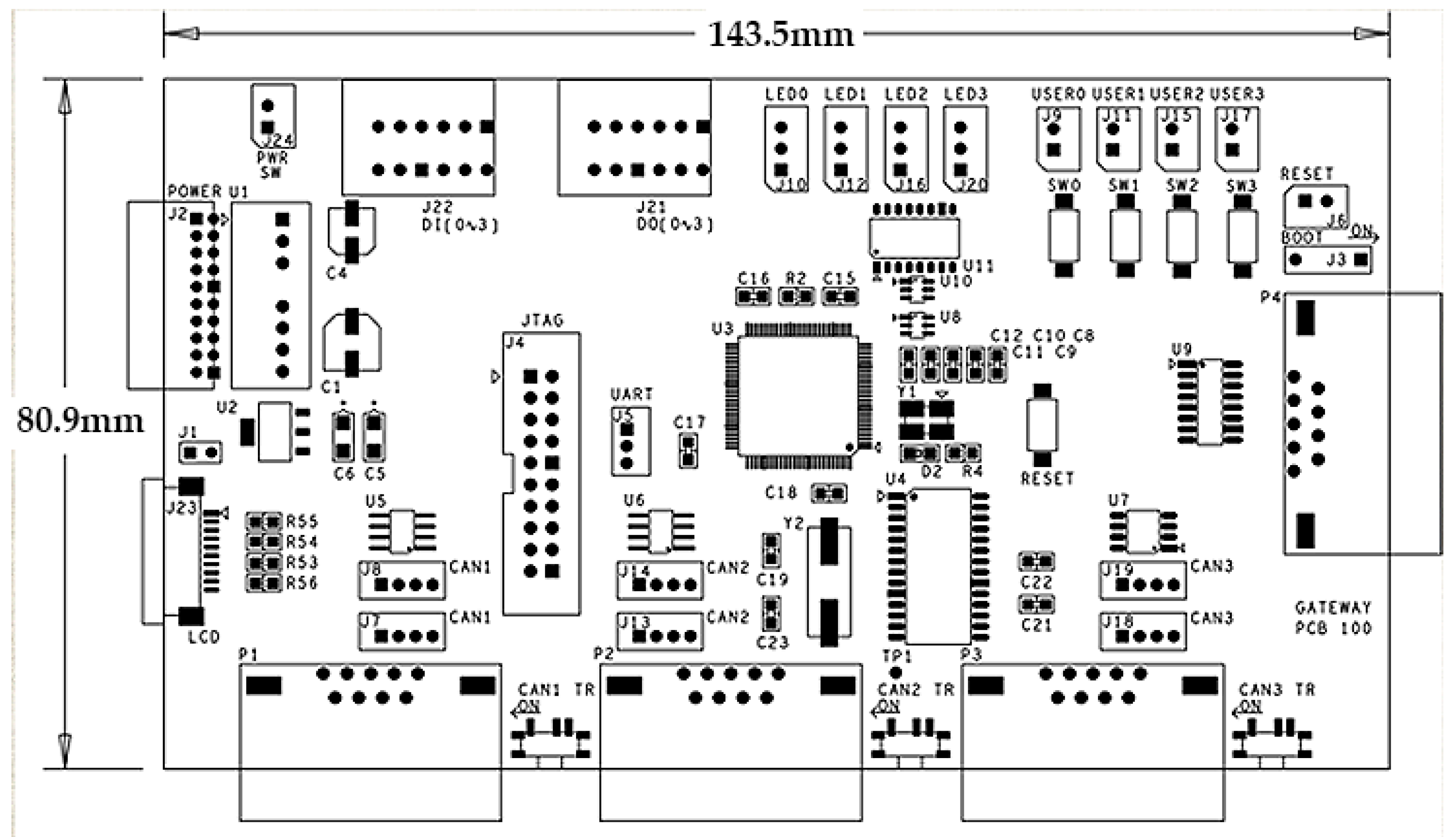
4.1. Modules and Software Development
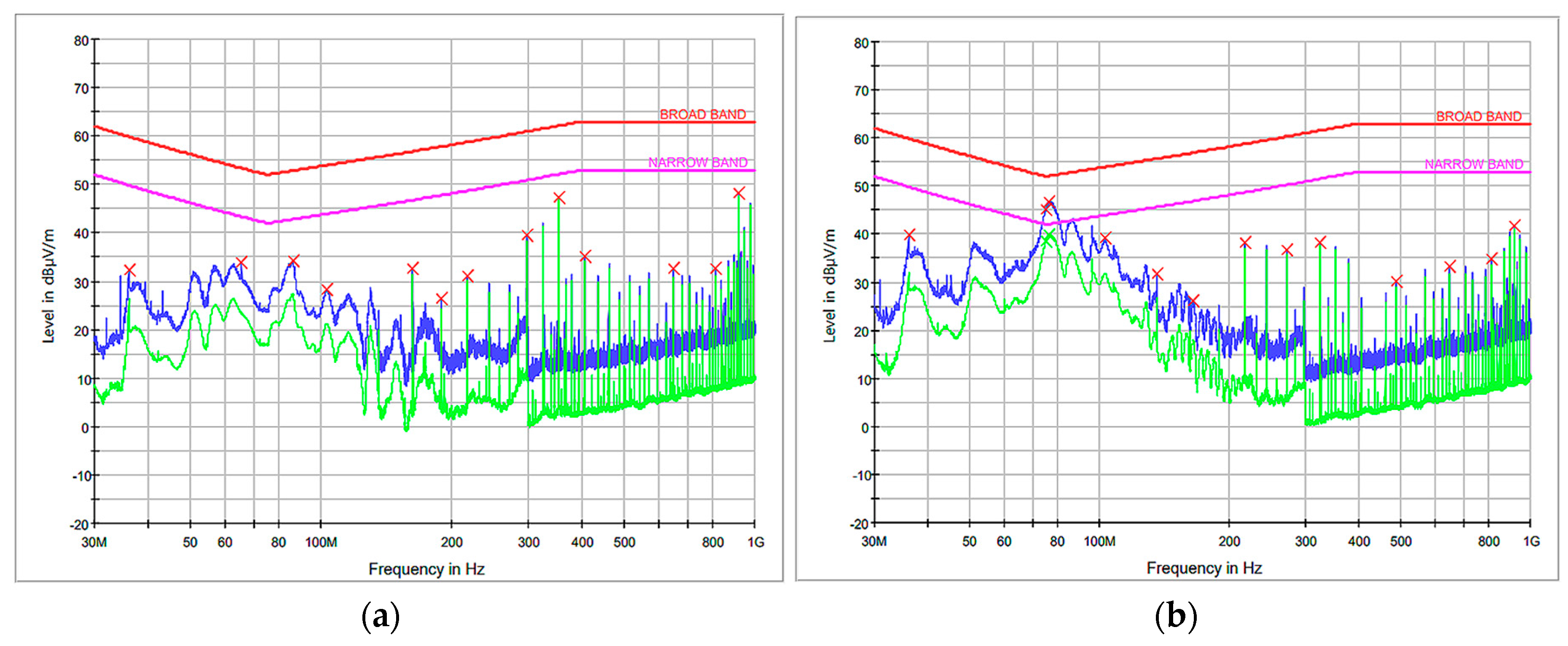
4.2. System TestingResults
4.3. Database Implementation
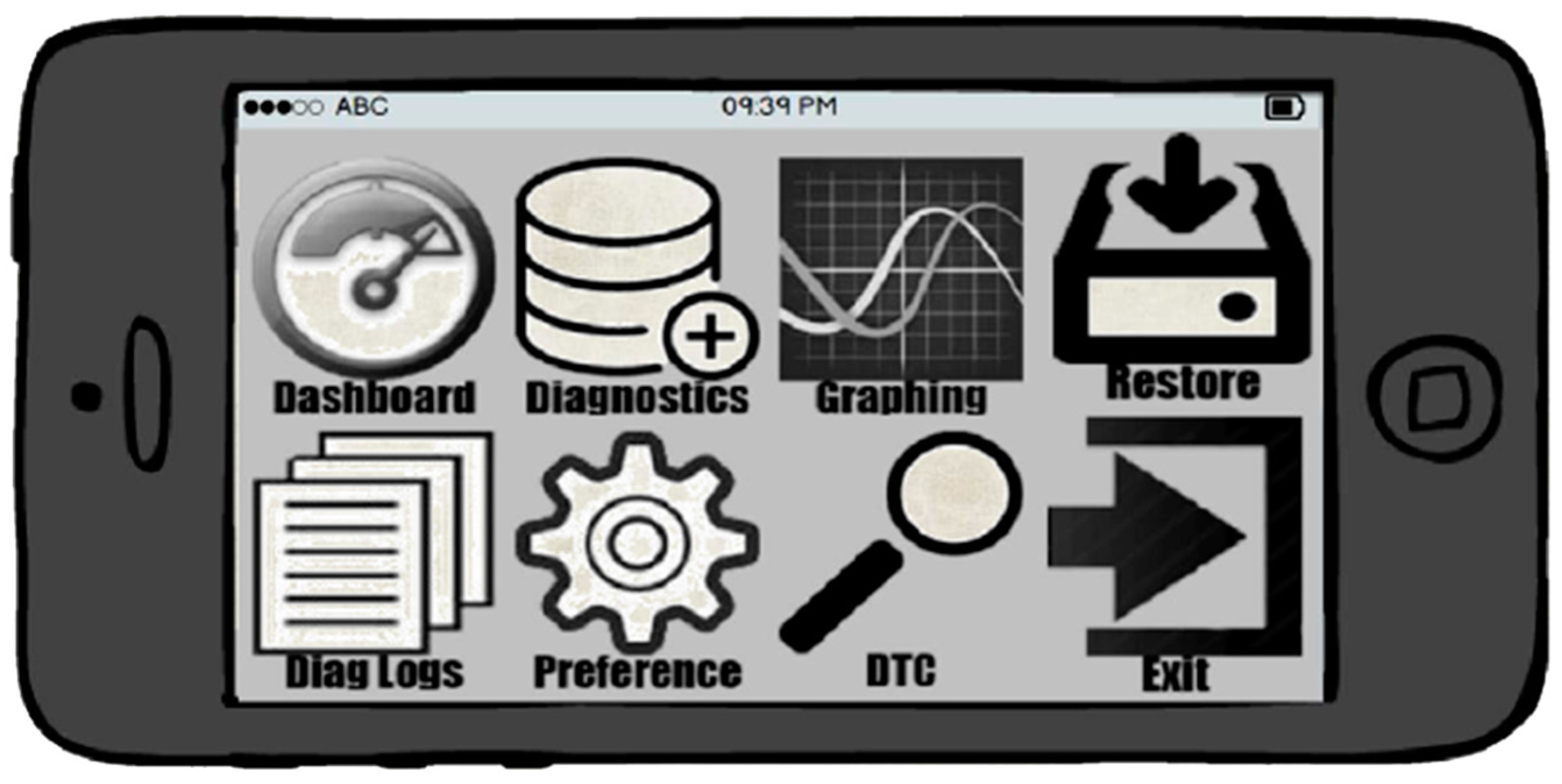
4.4. Mobile Application
4.5. Proposing A Cloud-Based Distributed File System for Big Data Analysis
- The main purpose is to share the information of diagnostics and driving.
- A variety of DFS’ need to be examined.
- Protocols to share and store the information of diagnostics and driving are web service-based.
- The collected information goes through preprocessing, and a software framework needs to be employed for data processing, analysis, and reporting.
- The analyzed result is provided to users through data visualization.
4.5.1. Google File System
4.5.2. Hadoop Distributed File System
4.5.3. Amazon Web Service
4.5.4. Microsoft Azure
4.6. Proposing Distributed File System Design
5. Conclusions
Acknowledgments
Author Contributions
Conflicts of Interest
References
- KPMG. KPMG’s Global Automotive Executive Survey. 2016. Available online: https://assets.kpmg.com/content/dam/kpmg/xx/pdf/2017/01/global-automotive-executive-survey-2017.pdf (accessed on 9 November 2016).
- Tesla. Model S Software Release Notes v7.1. 2016. Available online: https://www.tesla.com/sites/default/files/pdfs/release_notes/tesla_model_s_software_7_1.pdf (accessed on 9 November 2016).
- Baker, E.; Crusius, D.; Fischer, M.; Gerling, W.; Gnanaserakan, K.; Kerstan, H.; Kuhnert, F.; Kusber, J.; Mohs, J.; Schulte, M.; et al. Connected Car Report 2016: Opportunities, Risk, and Turmoil on the Road to Autonomous Vehicles. 2016. Available online: http://www.strategyand.pwc.com/reports/connected-car-2016-study (accessed on 8 December 2016).
- Mercedes-Benz Technology. Trend Analysis: Connected Car. 2015. Available online: https://www.mbtech-group.com/fileadmin/media/pdf/consulting/downloads/Trendanalyse_Vernetztes_Fahrzeug_2015_EN.pdf (accessed on 24 February 2017).
- Karen, R.; Eldridge, S.; Chapin, L. Internet Society. The Internet of Things: An Overview. The Internet Society (ISOC), 2015. Available online: https://pdfs.semanticscholar.org/6d12/bda69e8fcbbf1e9a10471b54e57b15cb07f6.pdf (accessed on 14 March 2017).
- Johansson, K.H.; Törngren, M.; Nielsen, L. Vehicle Applications of Controller Area Network. In Handbook of Networked and Embedded Control Systems, 1st ed.; Hristu-Varsakelis, D., Levine, W.S., Eds.; Birkhäuser Basel: Cambridge, MA, USA, 2005; pp. 741–765. [Google Scholar]
- Currie, R. Development in Car Hacking. SANS Institute, 2016. Available online: https://www.sans.org/reading-room/whitepapers/ICS/developments-car-hacking-36607 (accessed on 14 March 2017).
- Cook, J.A.; Freudenberg, J.S. Controller Area Network (CAN). 2007. Available online: http://www.eecs.umich.edu/courses/eecs461/doc/CAN_notes.pdf (accessed on 14 March 2017).
- Wolf, M.; Weimerskirch, A.; Paar, C. Security in Automotive Bus Systems. In Workshop on Embedded Security in Cars. 2004. Available online: http://www.weika.eu/papers/WolfEtAl_SecureBus.pdf (accessed on 15 March 2017).
- Suwatthikul, J. Fault Detection and Diagnosis for In-Vehicle Networks, 1st ed.; Zhang, W., Ed.; InTech: Rijeka, Croatia, 2010; pp. 283–306. [Google Scholar]
- Ueda, H.; Kurachi, R.; Takada, H.; Mizutani, T. Security Authentication System for In-Vehicle Network. SEI Technical Review, 2015. Available online: http://global-sei.com/technology/tr/bn81/pdf/81-01.pdf (accessed on 16 March 2017).
- Wang, Y.; He, L. The Application of Microcontroller MC9S08DZ60 in Automotive CAN Bus Electronic Control Unit. Open Electr. Electron. Eng. J. 2013, 7, 110–115. [Google Scholar] [CrossRef]
- Harding, J.; Power, G.; Yoon, R.; Fikentscher, J.; Doyle, C.; Sade, D.; Lukuc, M.; Simons, J.; Wang, J. Vehicle-to-Vehicle Communications: Readiness of V2V Technology for Application. 2014. Available online: https://www.nhtsa.gov/sites/nhtsa.dot.gov/files/readiness-of-v2v-technology-for-application-812014.pdf (accessed on 16 March 2017).
- Vegni, A.M.; Little, T.D.C. Hybrid vehicular communications based on V2V-V2I protocol switching. Int. J. Veh. Inf. Commun. Syst. 2011, 2, 1–18. [Google Scholar] [CrossRef]
- Auer, A.; Feese, S.; Lockwood, S. History of Intelligent Transportation Systems. 2016. Available online: https://ntl.bts.gov/lib/59000/59200/59263/download1.pdf (accessed on 17 March 2017).
- Araniti, G.; Campolo, C.; Condoluci, M.; Lera, A.; Molinaro, A. LTE for Vehicular Networking: A Survey. IEEE Commun. Mag. 2013, 2, 148–157. [Google Scholar] [CrossRef]
- Le, N.T.; Hossain, M.A.; Islam, A.; Kim, D.; Choi, Y.; Jang, Y.M. Survey of Promising Technologies for 5G Networks. Mob. Inf. Syst. 2016, 2016, 1–25. [Google Scholar] [CrossRef]
- Qualcomm Technologies Inc. Leading the World to 5G: Cellular Vehicle-To-Everything (C-V2X) Technologies. 2016. Available online: http://2pe5rtjld2w41m0dy17n5an1.wpengine.netdna-cdn.com/wp-content/uploads/2016/10/Qualcomm-Cellular-V2X-AESIN-Oct-2016.pdf (accessed on 17 March 2017).
- Nkenyereye, L.; Jang, J. Addressing Big Data Solution enabled Connected Vehicle Services using Hadoop. J. Korea Inst. Inf. Commun. Eng. 2015, 19, 607–612. [Google Scholar] [CrossRef]
- Boquete, L.; Rodríguez-Ascariz, J.; Barea, R.; Cantos, J.; Miguel-Jiménez, J.; Ortega, S. Data Acquisition, Analysis and Transmission Platform for a Pay-As-You-Drive System. Sensors 2010, 10, 5395–5408. [Google Scholar] [CrossRef] [PubMed]
- The R Foundation. Available online: https://www.r-project.org/ (accessed on 8 August 2017).
- The MathWorks Inc. Available online: https://www.mathworks.com/products/matlab.html (accessed on 8 August 2017).
- Python Software Foundation. Available online: https://www.python.org/ (accessed on 8 August 2017).
- Ghemawat, S.; Gobioff, H.; Leung, S. The Google file system. In Proceedings of the 19th ACM Symposium on Operating Systems Principles, Bolton Langding, NY, USA, 11–22 October 2003; pp. 29–43. [Google Scholar]
- Borthakur, D. HDFS Architecture Guide. 2008. Available online: https://hadoop.apache.org/docs/r1.2.1/hdfs_design.html (accessed on 17 March 2017).
- AWS Storage Services Overview. 2015. Available online: https://d0.awsstatic.com/whitepapers/AWS%20Storage%20Services%20Whitepaper-v9.pdf (accessed on 17 March 2017).
- Chappell, D. Introducing the Windows Azure Platform. 2010. Available online: http://www.davidchappell.com/writing/white_papers/Introducing_the_Windows_Azure_Platform,_v1.4--Chappell.pdf (accessed on 17 March 2017).


| Category | Frequency (MHz) | ||
|---|---|---|---|
| 30~75 | 75~400 | 400~1000 | |
| Broadband (dBμV/m) | 62–25.13 log(f/30) | 52 + 15.13 log(f/75) | 63 |
| Narrowband (dBμV/m) | 52–25.13 log(f/30) | 42 + 15.13 log(f/75) | 53 |
© 2017 by the authors. Licensee MDPI, Basel, Switzerland. This article is an open access article distributed under the terms and conditions of the Creative Commons Attribution (CC BY) license (http://creativecommons.org/licenses/by/4.0/).
Share and Cite
Kwon, D.; Park, S.; Ryu, J.-T. A Study on Big Data Thinking of the Internet of Things-Based Smart-Connected Car in Conjunction with Controller Area Network Bus and 4G-Long Term Evolution. Symmetry 2017, 9, 152. https://doi.org/10.3390/sym9080152
Kwon D, Park S, Ryu J-T. A Study on Big Data Thinking of the Internet of Things-Based Smart-Connected Car in Conjunction with Controller Area Network Bus and 4G-Long Term Evolution. Symmetry. 2017; 9(8):152. https://doi.org/10.3390/sym9080152
Chicago/Turabian StyleKwon, Donghwoon, Suwoo Park, and Jeong-Tak Ryu. 2017. "A Study on Big Data Thinking of the Internet of Things-Based Smart-Connected Car in Conjunction with Controller Area Network Bus and 4G-Long Term Evolution" Symmetry 9, no. 8: 152. https://doi.org/10.3390/sym9080152
APA StyleKwon, D., Park, S., & Ryu, J.-T. (2017). A Study on Big Data Thinking of the Internet of Things-Based Smart-Connected Car in Conjunction with Controller Area Network Bus and 4G-Long Term Evolution. Symmetry, 9(8), 152. https://doi.org/10.3390/sym9080152