Article

Interactive Blow and Burst of Giant Soap Bubbles

1
Department of Image, Graduate School of Advanced Imaging Science, Multimedia, and Film, Chung-Ang University, Seoul 156-756, Korea
2
Department of Integrated Engineering, Digital Imaging Major, Chung-Ang University, Seoul 156-756, Korea
*
Author to whom correspondence should be addressed.
Symmetry 2017, 9(4), 56; https://doi.org/10.3390/sym9040056
Submission received: 16 December 2016 / Revised: 10 April 2017 / Accepted: 11 April 2017 / Published: 14 April 2017

Abstract

:
Previous studies on virtual soap bubbles mainly focused on methods for visualizing the physical and geometrical properties of soap bubbles and paid little attention to the possible ways to enhance the interaction between the simulation and the user. In this paper, a user interaction-based giant soap bubble simulation system is proposed in which the free-form shape, size, and position of giant soap bubbles are determined by the user’s hand motions. Our method improves the controllability of soap bubble simulation by correcting the jerky hand trajectory and hand velocity to a smooth and gradual path. Our air flow transfer algorithm can produce detailed deformation and standing wave for soap film in real time. Our novel soap film bursting algorithm represents the process of the bursting phenomenon of soap-film and giant soap bubbles in a unified framework. The results of our experiment demonstrate that the system allows the user to experience the giant soap bubble blowing and bursting process in a virtual environment.

Graphical Abstract

1. Introduction

Because of their striking shapes, deformations, and various colors, giant soap bubbles are widely used in bubble shows, children’s entertainment, and public presentations [1]. 
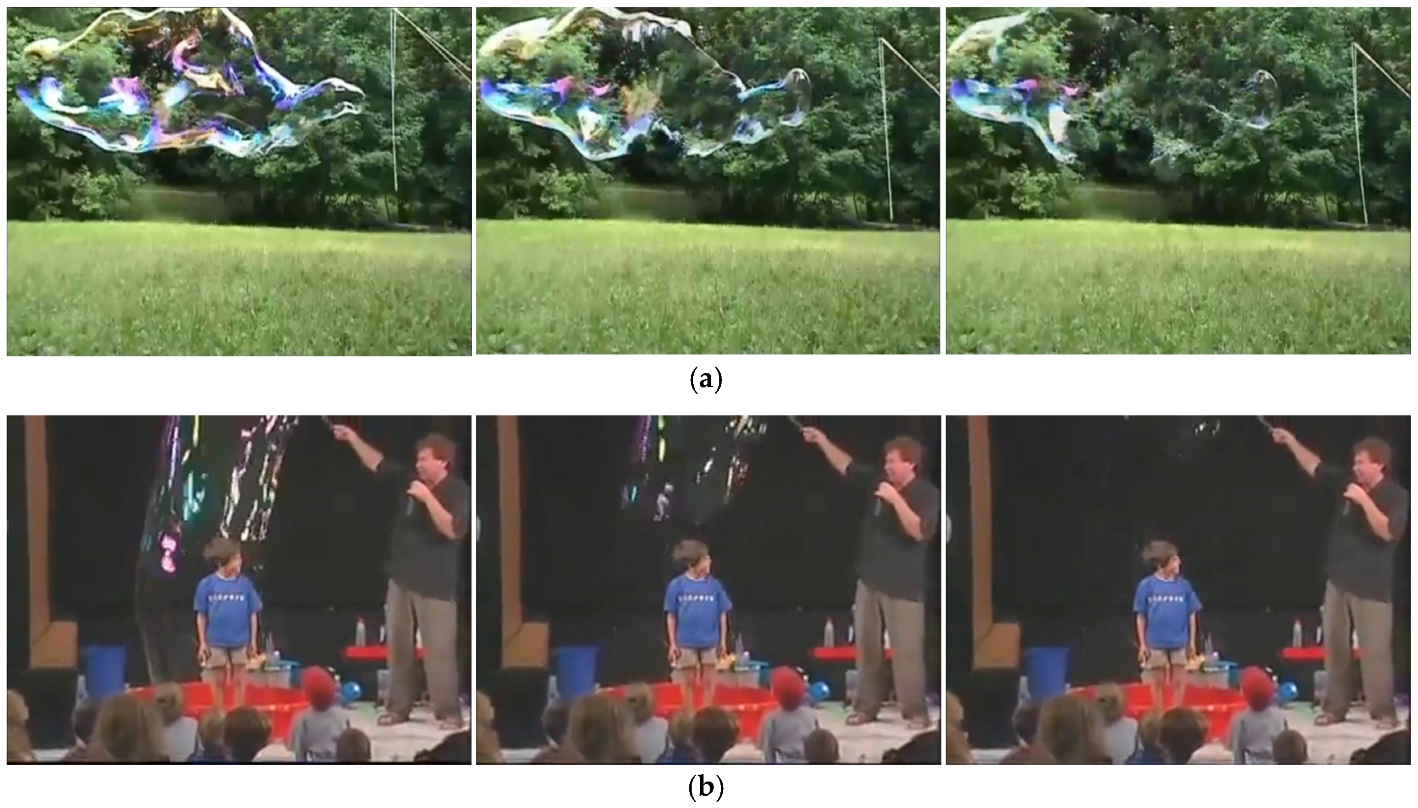
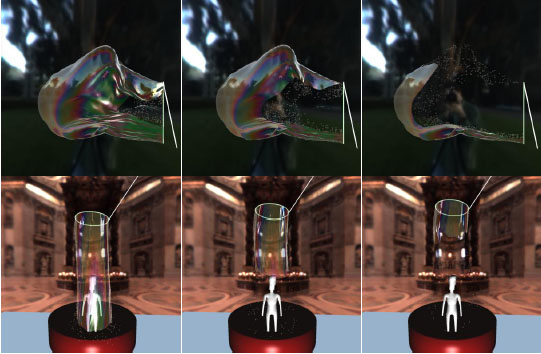
Figure 1 shows the photographs of a real giant soap bubble blowing and bursting. Making giant soap bubbles requires skillful techniques, a highly viscous soap solution, tools such as bubble wands, and a demonstration space. If a method can be found that simulates realistic giant soap bubbles, and which can automatically reflect the user’s motion, the practicality issue could be solved in the virtual world. However, managing both the control of the user’s motion and the visual realism of the giant soap bubble simulation is extremely challenging.
To address the existing issue, we propose an efficient approach that automatically demonstrates a giant soap bubble driven by the user’s hand movements in a virtual environment. The proposed system controls the shape, size, and position of the bubble in real time by the user’s hand movements. It also allows the user to experience various shapes of the soap bubble making process. Since our system recognizes the movement of the user’s hands without an object attached to the human body, it is more comfortable and user-friendly than the motion capturing technology based device that attaches the marker to the user’s body. In addition, the proposed system is more convenient and less costly than the technology that features a haptic device, because our method recognizes the movement of both the left and right hands of the user with one Kinect which is a consumer level depth camera widely used in the gaming industry.
The bursting phenomenon of small spherical soap bubbles occurs extremely quickly and is thus difficult to observe with the naked eye. Nevertheless, the bursting phenomenon of giant soap bubbles at a meter scale is an important factor for visual realism. Since the soap film is extremely large with giant soap bubbles, the progress of the soap film bursting can be visually observed. Although a previous method [2] has been introduced to generate the realistic and detailed bursting phenomenon of soap bubble, the method is still computationally expensive to use in interactive applications and did not consider drainage. This paper offers a method of simulating the details of the phenomenon of soap film bursting based on hole opening propagation and position-dependent draining in real time. In addition, the shape and the size of the soap bubble can be adjusted according to the amount of remaining soap solution.
Kim et al. [3] proposed a giant soap bubble method that makes the versatile shape of soap bubbles from a soap film by incorporating the surface tension effects into deformable models. For time-varying surface tension, they introduce Gibbs elasticity and Marangoni elasticity adaptively depending on the material properties of soap films. They also present a re-meshing method for topological change from a soap film into a soap bubble. Their method focuses on the animating the evolving process of soap films into giant soap bubbles in a way to keep minimal surfaces, show local oscillations on surfaces, and result in realistic animation of soap bubbles. However, they did not consider the effects due to external forces including bubble bursting, air inflow, and user interventions during simulation. Therefore, it is necessary to develop soap film bursting and air inflow methods for interactive simulation system of giant soap bubbles and also to modify a force generation method to apply continuous user interventions during simulation.
We extend and modify an existing method [3] so that users interactively build giant soap bubbles as they move both of their hands. Our major technical contributions are as follows: (1) we introduce an interactive blowing and bursting system of giant soap bubbles; (2) we generate smooth user exerted force over time by interpolating the tracked hand motion; (3) we present the bursting animation method of soap film that introduces local draining parameters due to deformations and gravity, makes a hole on soap film meshes, and propagates the holes gradually; and (4) we visualize the standing waves in the soap film, due to movements of wands, using an air flow transfer method.

2. Related Work

2.1. Related Work in Human Interaction Using Kinect

In recent years, a considerable number of studies have been actively conducted to recognize human motion and handle user interaction using Microsoft Kinect. Murata and Shin [4] proposed a method to recognize alphabets and numbers represented by hand movements, and Yang [5] introduced a method to recognize sign language from hand movements and shapes. A study was conducted to analyze the home gait based on Kinect and perform a fall risk assessment for the elderly [6]. Another study was proposed to estimate the control parameters of a virtual simulator for military training from trainer skeleton information [7]. Choi et al. [8] proposed a method that generates character juggling skillfully using the motions of a novice user with a Kinect. These previous works focused on methods of analyzing and recognizing human movements using Kinect, but it is difficult to find a study in which 3D bubble simulations of virtual environments are driven by human motion.

2.2. Related Work in Soap Bubble Simulation

Numerous studies have been carried out to physically simulate and model soap bubbles. Durikovic [9] proposed a method to create small spherical soap bubbles from a fixed round tube and simulate elastic deformations based on a mass-spring system. Wei et al. [10] simulated deformation and oscillation of soap bubble using spherical harmonics, and Huszar and Szecsi [11] proposed a fast method that renders dense soap foam and models foam interaction. Zheng et al. [12] presented a regional level set technique to represent complex bubble clusters, and Pan et al. [13] proposed a robust method to model soap films and soap bubbles based on an energy minimization approach. Recently, Da et al. [14] proposed a technique that simulates realistic bubble clusters and deformation of soap films and bubbles using a Lagrangian vortex sheet, and Kim et al. [3] introduced a method to simulate the formation of giant soap bubbles by using the varying surface tension with Gibbs-Marangoni elasticity. These previous studies focused on developing algorithms that handle the physical and geometrical characteristics of soap films and soap bubbles, whereby the motion of the blowing tool was simulated with a manual input or fixed state. To the best of our knowledge, no efficient method is available that allows users to experience the blowing and bursting of 3D soap bubbles by their motions.

2.3. Related Work in Air Effects

Many physics-based modeling techniques have been presented to simulate the air effects of soap bubble and cloth. A study that simulates the interaction of a wind field with a lightweight deformable object including soap bubble has been proposed [10], but it did not consider the air effect inside the soap bubble. The inflatable model [15], in which air is inflated inside the deformable surface, has been proposed, but it focused on the air pressure inside the deformable surface and did not consider air flow. The giant soap bubble creation model [3] has been proposed, but it treated air effect as air pressure based on Young Laplace’s law. Chen et al. [16] proposed an efficient technique that realistically simulates air effects between cloth and a deformable object based on Darcy’s law and the air transfer method. However, these previous studies that deal with air effects of the soap bubble and cloth did not take into account the air flow inside the giant soap bubble.

3. System Overview

The system proposed in this study focuses on enhancing the controllability and reality in the giant soap bubble simulation. The system pipeline and system configuration for this study are shown in Figure 2 and Figure 3. The system can be separated into three major components as follows: (1) User Interaction: refines the motion of the user’s hand through the trajectory stabilization and velocity stabilization and converts the stabilized hand movement into a controllable wand motion; (2) Soap Bubble Simulation: animates giant soap bubbles through a physics-based simulation framework including air flow and surface tension; and (3) Geometry Processing: realistically represents the soap film bursting and soap solution control by efficient mesh processing.

4. User Interaction

We apply a stabilization method to minimize the input noise of the Kinect depth camera and to facilitate the ease of making virtual soap bubbles. Through the proposed user interaction approach, the shape, size, and position of the soap bubble can be controlled according to the user’s hand movements.

4.1. Hand Position Acquisition

The shape of the soap bubbles is largely determined by the movement of the bubble wand, which is in turn influenced by the movement of the user’s hands. Since the user uses the wand in the hand when manipulating the bubble wand, the individual movement of the fingers and the snap of the wrist have little effect. Therefore, we focus on the motion of the user’s hands and convert the motion of the user’s left hand and right hand into the movement of the left wand and right wand in the virtual world. We then use the tracked wrist positions obtained by the skeleton tracking of the Kinect SDK as the positions of the user’s hands.

4.2. Hand Trajectory

Since Kinect is a camera device, it is difficult to acquire fundamentally perfect three-dimensional coordinates, and noise and drift can occur. A stabilization method is needed to minimize problems such as noise, drift, and the recognition rate of the Kinect. To overcome these problems, we employ a B-spline curve to stabilize the Kinect input data. This approach was successfully used as a rapid smoothing method for motion planning trajectories in a previous robotics study [17]. The B-spline curve passes only the start and end control points, and excludes the control points that are significantly outside of the path. This feature of the B-spline curve makes it possible to convert jerky paths into smooth paths.
Our approach deals with stabilization using a cubic B-spline. A B-spline curve is defined as a linear combination of control points and B-spline basis functions, and the method of constructing the B-spline basis functions is based on that found in the literature [18]. The B-spline curves are updated by adding the tracked hand positions as a control points of the B-spline curve at each frame. For each frame, the points on the B-spline curve are searched sequentially to obtain smoothed hand trajectory data.

4.3. Hand Velocity

If the velocity of the wands is adjusted constantly, the soap film does not burst satisfactorily, rendering the giant soap bubbles easier to form. We apply hand velocity stabilization to prevent any sudden change of wand velocity. The hand velocity is obtained using the finite difference method [19], and we add hand velocity to the control point of the B-spline curve. This stabilized hand velocity ( v h a n d t ) is applied to the Euler integration to obtain the position of the wand as shown in Equation (1). Then, the position of the wand calculated in the Kinect coordinates is converted into the 3D world coordinates where the simulation is performed. Through this, wand trajectory with the property of a smooth and gentle shortcut is created for smooth wand movement. Figure 4 shows the input hand trajectories from the Kinect, the interpolated hand trajectories using the B-spline, and the wand trajectories.
x w a n d t + h =   x w a n d t +   h v h a n d t

5. Soap Bubble Simulation

We use a unified framework to simulate soap film and bubbles, which consists of a thin shell model based on a mass-spring system. Each soap molecule is represented by a particle, each particle is connected to the neighboring particles by springs, where the rest length l i j is determined by the initial distance between connected particles. Our thin shell model is governed by the Lagrangian dynamics equation of motion by the following equation:
m i x i ¨ = f i s + f i d + f i n + f i p + f i x
where m i is the mass of particle p i , x i is the position of particle p i , and x i ¨ is the second derivative of x i with respect to time. Applied forces are given by surface tension f i s , damping force f i d , air inflow force f i n , air pressure force f i p , and external force f i x . External force consists of gravity and other force fields, and damping force is proportional to the velocity difference projected onto the spring.

5.1. Surface Tension

A soap bubble gradually evolves into a minimal surface with symmetric properties. This occurs because of the effect of surface tension. Surface tension that minimizes the surface area of the soap bubble is given by the following equation:
f i s = E i j ( | x j x i | l i j ) x j x i | x j x i |
where l i j is the rest length of a spring that is connected from p i to p j , x i and x j are the positions of particles p i and p j respectively. E i is the varying elasticity of particle p i , and is obtained separately. We apply Marangoni elasticity [3] to the initial soap film, which diffuses the surfactant evenly on the soap film. We then apply Gibbs elasticity [3] to the soap film, which allows the soap bubble to reach a minimal surface. Marangoni elasticity is proportional to the surfactant concentration and Gibbs elasticity is in inverse proportion to the thickness of soap film. E i is given by the following:
E i =   { 2 w E e i k e i + 2 k   Marangoni   Elasticity :   life   time   < 10 4 w E e i k 2 ( e i + 2 k ) 2   Gibbs   Elasticity :   life   time   > 10
where k is typically 4 μm, w E is typically 12.3. The thickness of soap film e i is given by the following: e i = w e A V o r ( p i ) , where w e is the area weight and A V o r ( p i ) is the Voronoi area [20] of particle p i . The pseudo code for surface tension force and damping force is shown in Algorithm 1.
Algorithm 1 Pseudo-code for surface tension and damping force
1: for all springs do
2:    x i , x j : position of connected particle by spring
3:     f i s = E i ( x i x j l ) x i x j x i x j
4:     f j s = E j ( x j x i l ) x j x i x j x i
5:     f i d = k d ( v j v i ) · x j x i x j x i
6:     f j d = f i d
7: end for

5.2. Air Effects

Bubble artists generate a variety of deformations and standing waves in soap film using air effects created by the movement of the wand to make giant soap bubbles with complex and detailed surfaces. This study proposes an efficient method that focuses on the air flow in order to realistically represent this air effect. First, we model the air inflow created by the movement of the wand. We then propose an air flow transfer algorithm that handles the phenomenon in which the air flowing into the soap film is transferred. After the soap film is converted to a soap bubble, we treat the air pressure in consideration of the air flow inside the soap bubble.

5.2.1. Air Inflow

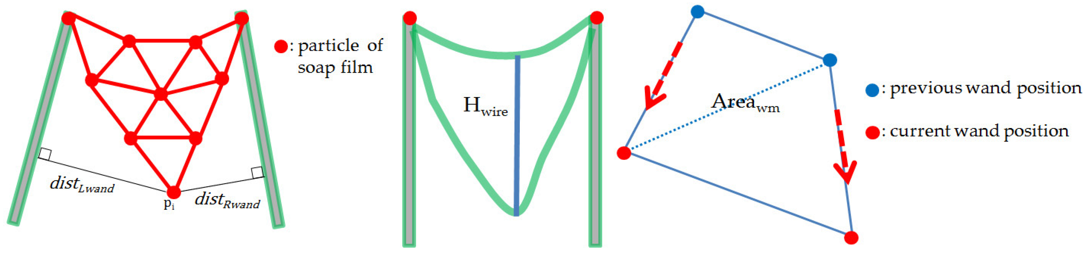
We estimate the local air inflow using the relation that the air inflow is inversely proportional to the distance between each wand and each soap film particle. The air inflow for particle p i created by the motion of the wand is calculated using the following equation:
a i r i = V w m ( M A X ( cos θ ,   0 ) ( v L d i s t L w a n d + 1 + v R d i s t R w a n d + 1 )
V w m = H w i r e A r e a w m
where d i s t L w a n d and d i s t R w a n d are the distances from the particle p i to the left and right wands, respectively. v L is the velocity of the left wand, v R is the velocity of the right wand, and θ is the angle between the velocities of the left and right wands. As the direction and velocity of the left and right hands become more similar, the soap film becomes more inflated. For example, when the left and right wands are gathered together, the soap film does not inflate. V w m is an approximation of the air volume generated by the movement of the left and right wands, and H w i r e is the height of the wire, and A r e a w m is the area where the wands move. 
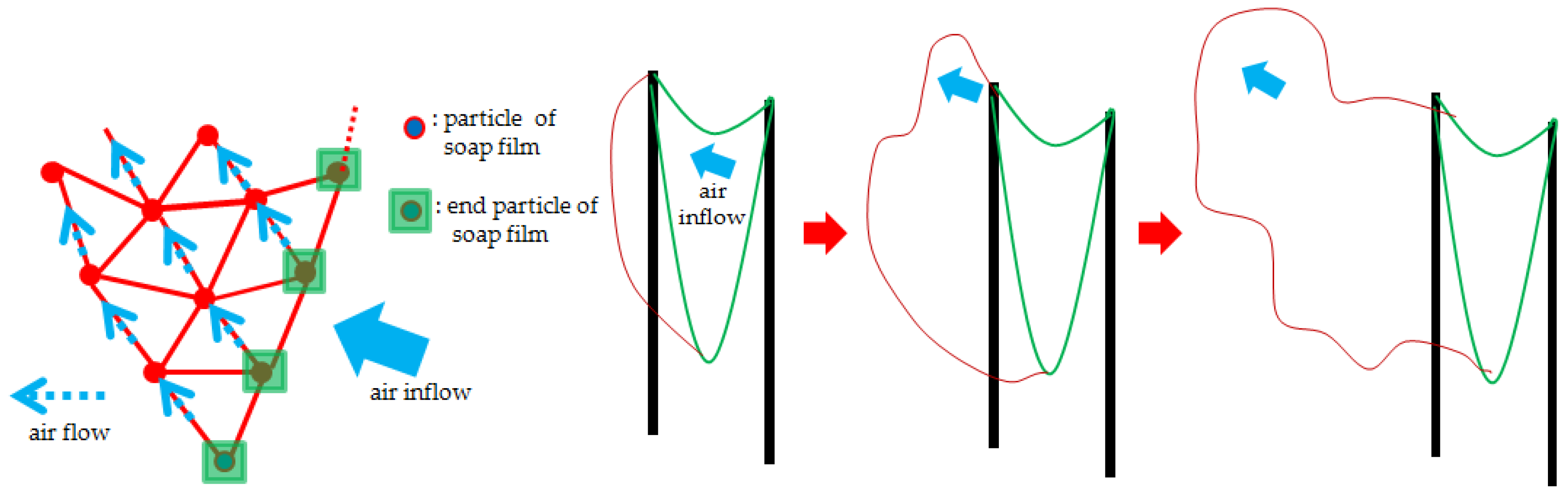
Figure 5 shows a schematic diagram of the air inflow.

5.2.2. Air Flow Transfer

Dynamic volumetric air flow methods (such as that of [21]) can simulate realistic air flows at a reasonable computational cost, but they can cause large deformations and self-collisions in giant soap film mesh undergoing topological change. We exploit the triangle elements that convey thickness of soap film meshes and material properties based on Gibbs and Marangoni elasticity. These properties are varied spatially and temporally during simulation and are the key factors of our proposed method. Therefore, our approach requires the same mesh connectivity from the beginning and is based on an explicit modeling method that is difficult to handle topological changes. This study proposes a new air flow transfer method, inspired by an existing, efficient air transfer method between cloth and a deformable body [16], as an alternative to solving this problem in real time.
The effect of air flow transferred into the inflated soap film is processed in a fast and efficient manner. The schematic diagram of the algorithm is shown in Figure 6 and the pseudo code is shown in Algorithm 2. Since air inflow is created due to the movement of the wand, the air flow transfer is handled from the end particles of soap film which is first affected by the movement of the wand. First, the generated air inflow a i r i is assigned to the end particles. We then progressively propagate the a i r of each particle to its neighboring particles of which the direction is similar to a i r . Whether the direction is similar to a i r i is determined by a d i r > λ a i r , where λ a i r is typically selected from 0.5 to 0.7, and a d i r is given by the following:
a d i r =   M A X ( ( x j x i ) · a i r i | x j x i | | a i r i | , 0 )
air j f = a d i r a i r i a d i r
where x i is the position of the currently selected particle and, x j is the location of a neighboring particle.
Algorithm 2 Pseudo-code for Air Flow Transfer
1: if air inflow is created
2:   assign a i r i to the end particles
3: for each particle p i do
4:   if particle p i has air flow then
5:     for each particle p j one-ring neighborhood particles of particle p i do
6:       if a d i r > λ a i r then
7:       add air i f to air j f
8:     end for
9:   delete air i f
10: end for
We apply the air inflow force f i n before the soap film is converted to the soap bubble, which is given by the following equation:
f i n = proj n i air i f + proj n i a i r i
where n i is normal vector of particle p i . proj n i air i f represents the force applied to the soap film by the air flow transferred to the inflated soap film, and proj n i a i r i represents the force with which the air inflow a i r directly acts on the soap film. The air inflow force describes the air flow transferred to the inflated soap film and the air inflow directly acting on the soap film.

5.2.3. Air Pressure

A large amount of air is contained inside the giant soap bubble, and the air flow is high. Because of this internal air flow, the deformation and standing waves of the giant soap bubbles are enhanced. Our proposed method efficiently represents the phenomenon of air flow interaction inside a giant soap bubble based on air flow transmission, whereby the air flow transfer is performed until the bubble bursts. The air pressure force of each soap film particle is given by following equation:
f i p = P c u r proj n i air i f
where P c u r is the pressure coefficient of the current bubble calculated based on Boyle’s law, which explains that the pressure of the bubble is inversely proportional to the volume of the bubble. P c u r is given by the following equation:
P c u r =   ( P 0 V 0 ) / V c u r
where P 0 = 1.01 kPa is the atmospheric pressure coefficient, V 0 is the volume of the initial bubble, and V c u r is the volume of the current bubble.

5.3. Time Integration

We use semi-implicit time integration to update the position and velocity of particles at each time step. The efficiency of semi-implicit time integration was recently effectively used for a deformable surface model of a water drop [22], flower [23], and cloth [24]. Since the motion of the soap bubble is dominated by the boundary surface due to the surface tension effect, semi implicit time integration can preserve the surface detail. The position and velocity of a particle is updated using Equation (3) at each time step,
v i t + h =   v i t +   h f i t / m i
x i t + h =   x i t +   h v i t + h
where h is the time step, x i t and v i t are the current position and velocity of particle p i , respectively, and x i t + h and v i t + h are the position and velocity of particle p i , respectively, at the next time step.

6. Soap Film Bursting

The main cause of the bursting of the soap bubbles is draining [25] or excessive stretching. The bursting of giant soap bubbles is an important factor for visual realism because the progress of the soap film bursting is discernible to the naked eye, unlike small spherical soap bubbles. In order to represent this phenomenon realistically, this study is based on the principle of hole opening propagation which has been widely studied in the field of physics. The principle of hole opening propagation [26] explains the phenomenon in which the cracks propagate outward from the point of puncture when the soap film cracks. This phenomenon is described by Taylor Cullick’s Law [27,28]. Based on this principle, we propose a method that generates the soap film bursting in real-time for the soap film and the soap bubble in a unified framework.

6.1. Hole Opening Propagation

The conceptual diagram of the proposed method is shown in Figure 7 and the pseudo code is shown in Algorithm 3. First, we define the occurrence of the cracks in the particles of which the thickness is thinner than thickness threshold ( λ t h i ) due to draining or excessive stretching. The crack is transferred by removing the adjacent particles of the crack. When all three particles constituting the triangle are removed, the corresponding triangle is removed from the mesh. In addition, we represent the appearance of aerosol [25] composed of soap molecules and water molecules constituting the soap film when the soap film burst by generating spherical particles at the center of gravity of the removed triangles. Each spherical particle is evenly distributed over the properties of the three vertices corresponding to a triangle, such as force, velocity, and mass.
Algorithm 3 Pseudo-code for Soap Film Bursting
1: Capture particles of which the thickness are thinner than λ t h i
2: Set up these particles as bursting particles.
3: Set one-ring neighborhood of bursting particles as next-bursting particles
4: Remove bursting particles and their springs.
5: if all three particles constituting the triangle are removed then
6:   Remove the corresponding triangle from the mesh.
7: Copy next-bursting particles to bursting particles.
8: Remove next-bursting particles.
9: Repeat step 3~8 until all particles have burst.

6.2. Position-Dependent Draining

Drainage is a natural phenomenon in which the water in the walls of the soap bubble drains to the bottom of the soap bubble. Because the previous draining model [12] linearly decreases the thickness of the small bubble, their model does not handle position-dependent movement of a water molecule for a large bubble. We propose a novel drainage model based on water molecule propagation which considers the movement of the water molecule and topology change. Our drainage model progressively propagates the water molecule of each particle to its neighboring particles, the directions of which are most similar to the gravity direction using the following equation:
d d i r =   M A X ( ( x j x i ) · g | x j x i | | g | , 0 )
e j   + = d d i r / S t i c k y ,   e i   = d d i r / S t i c k y
where g refers to gravity. S t i c k y refers to the viscosity of the soap solution, where S t i c k y is increased to delay drainage and extend the life of the soap bubble. d d i r determines the degree to which the direction of the neighboring particles are similar to the gravity direction. Figure 8 shows our drainage results, where the top region becomes thinner and the bottom region becomes thicker because water molecules on the top region move to the bottom region over time under the influence of gravity.

7. Soap Solution Control

Because our model is based on the assumption that a wire frame is made wet by a soap solution, the first soap film is initially created. As the amount of remaining soap solution is decreased, the amount of soap film stretching also decreases, so that the shape of the soap bubble becomes rounder and the size decreases. To mimic this phenomenon, we dynamically adjust the mesh resolution of the soap film in proportional to the amount of remaining soap solution. We adjust the number of soap film particles placed on the wire frame in proportion to the amount of residual soap solution, and place the soap film particles on the wire frame using spherical linear interpolation. We then create a triangular mesh using Delaunay Triangulation [29] and then modify the edges of the mesh into springs. Figure 9 shows that the shape and size of the soap bubble varies in proportion to the amount of remaining soap solution.

8. Experimental Results and Analysis

We implemented the system using KinectSDK-v1.8 (Microsoft, Redmond, WA, USA) and multi-threading, which runs on an Intel i5 3.2 GHZ (Intel Corporation, Santa Clara, CA, USA), 16 GB RAM, Nvidia GTX 560 (NVIDIA, Santa Clara, CA, USA) PC with one Kinect. The proposed system controls the wand motions based on the user’s hand motions that are tracked with from Kinect input, and the air inflow, air flow transfer, and soap film bursting are simulated according to the wand’s motion. We employ a previous rendering method [3] for realistic soap bubble rendering to represent interference and reflection, as well as the refraction phenomenon in real time. The self-collisions of the soap bubble are detected using a bounding volume hierarchy [30] and the collision response is computed using collision forces [22], which result in slipping of the colliding particles. If the impact with which the soap film collides is higher than the colliding threshold ( λ c o l ), the soap film bursts.
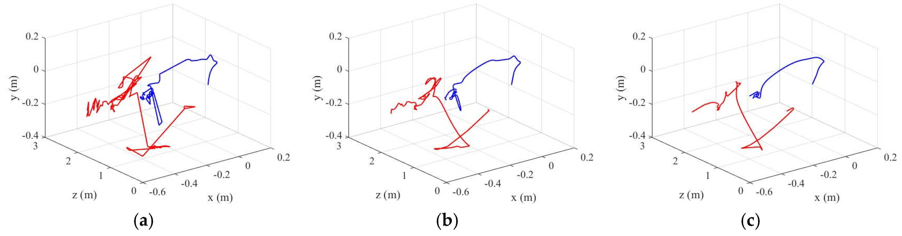
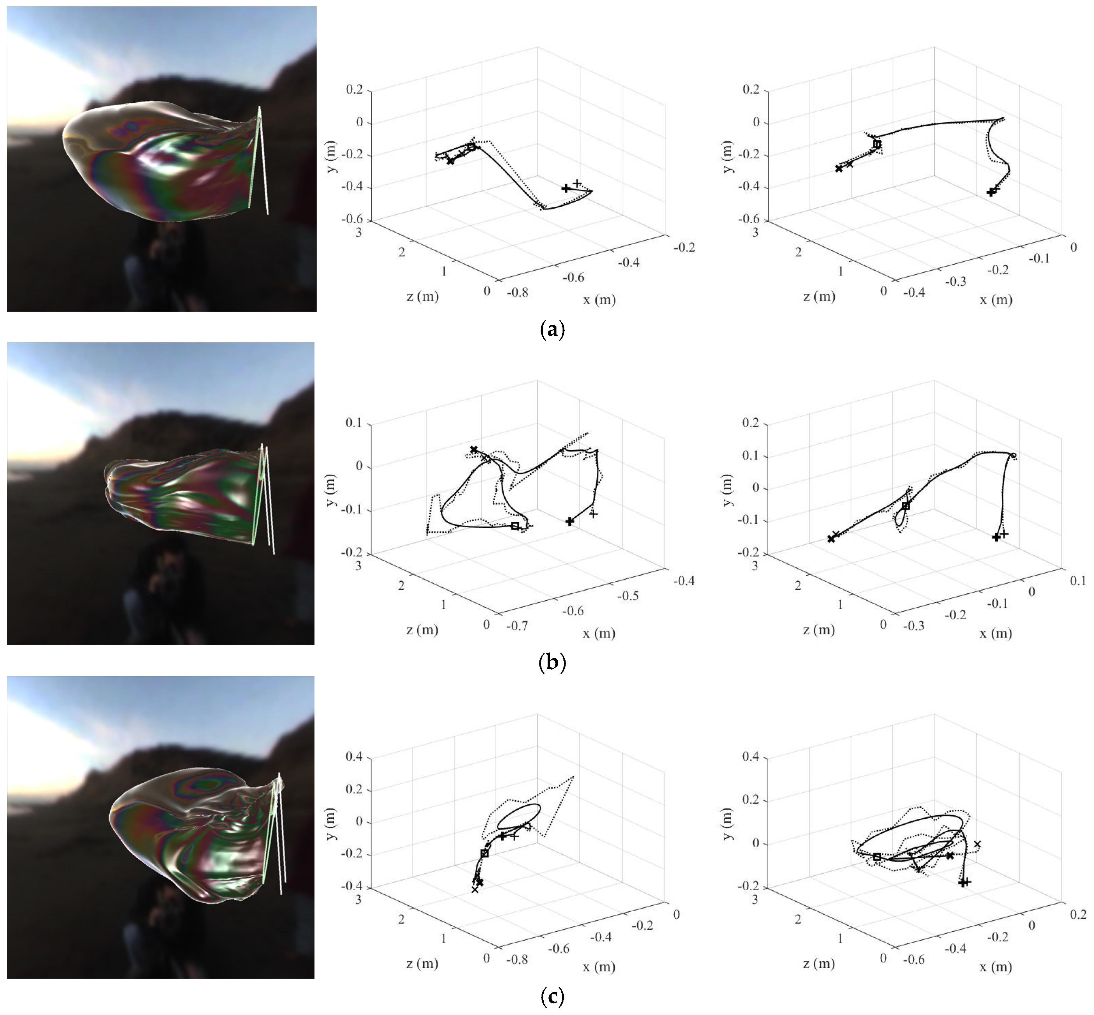
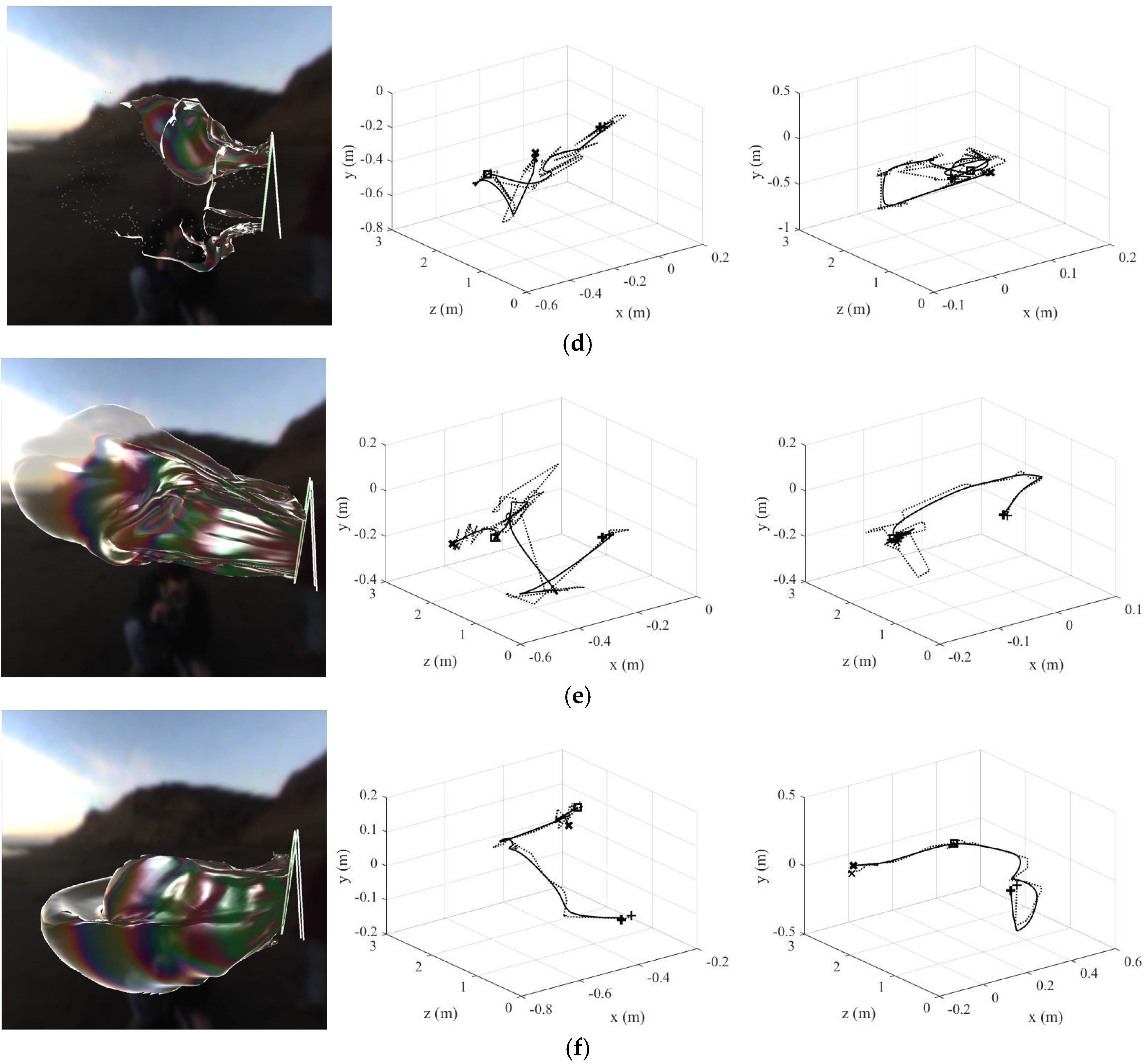
Figure 10 shows the simulation results according to the user’s hand movements (left), including the left wand trajectory (middle), and the right wand trajectory (right). It also shows the input hand trajectory (dotted line), wand trajectory (full line), starting point (+), end point (×), and current point (square). Figure 10a shows that when the trajectories of the left and right wands are straight with few redirections, the soap bubble grows in a straight direction. Figure 10b shows that when the trajectory of the left wand moves in a circle and the trajectory of the right wand is straight, ridges and valleys appear on the left side of the soap bubble. Figure 10c shows that when the trajectories of the left and right wands all move in a circle, ridges and valleys appear throughout the soap bubble. Figure 10d shows that when the trajectories of the left and right wands are increasingly redirected and twisted, and the number of movements is large, the soap film bursts. Figure 10e shows that when the trajectories of the left and right wands are less twisted, the number of movements is large, and when the left and right wands move up and down, the soap bubble is inflated further. Figure 10f shows that when the left and right wands are moved up from the bottom, the soap bubble is tilted downward and ridges and valleys appear at the top of the bubble.
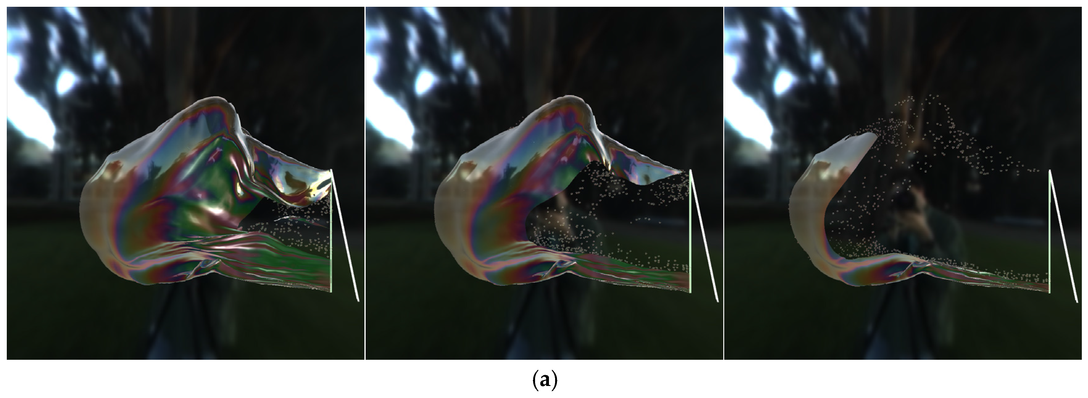
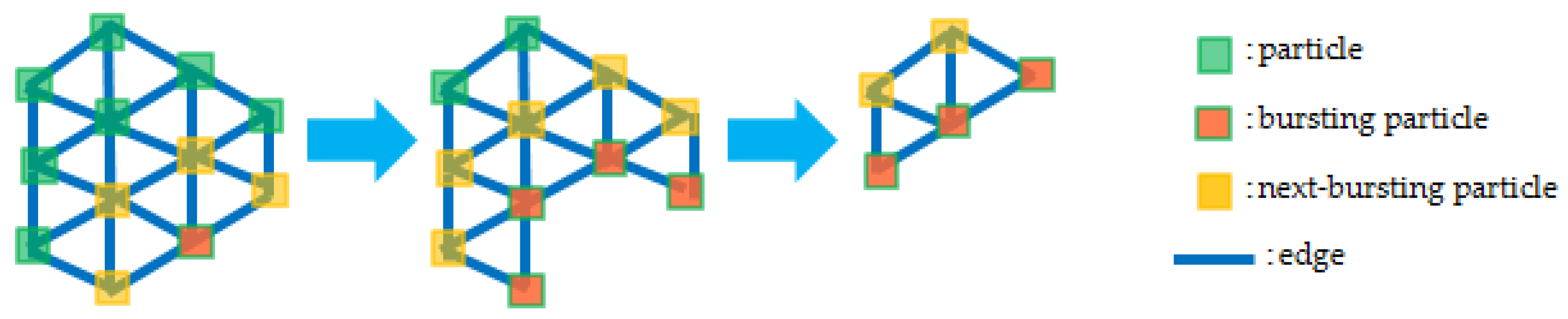
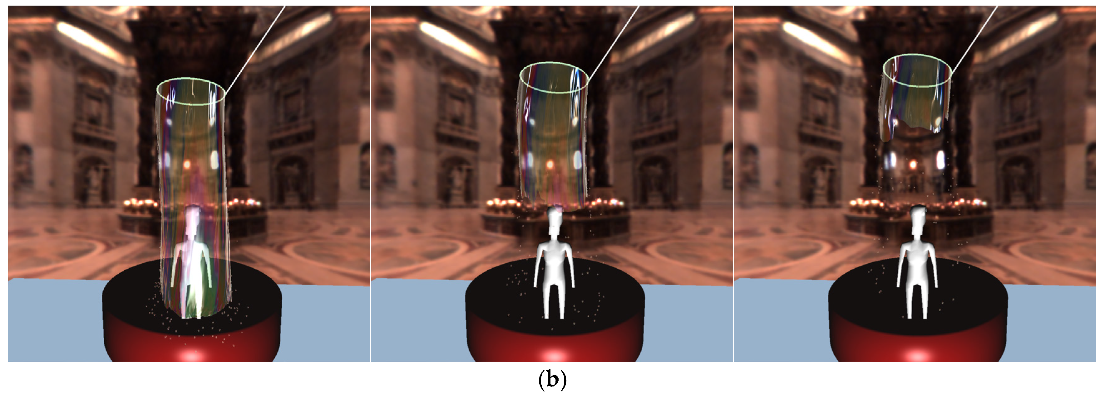
Figure 11 shows the simulation results of the soap film bursting method. As the crack propagates in the outward direction, the bursting soap films transform into spherical particles similar to those of an aerosol.
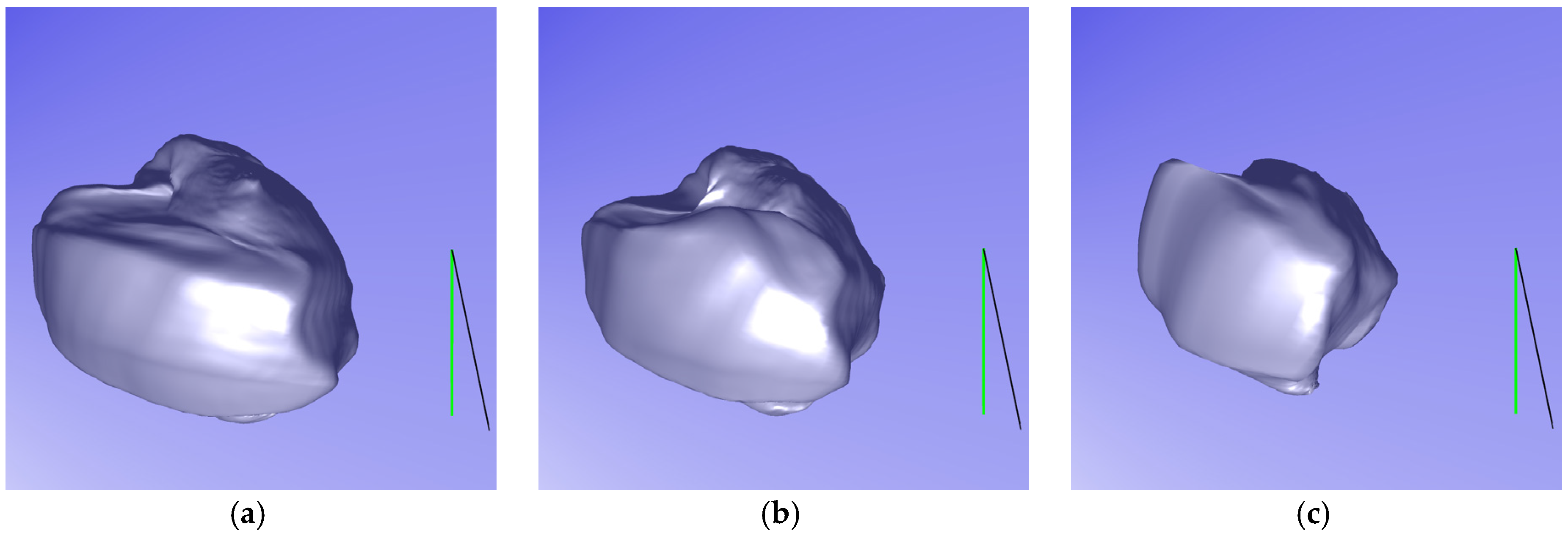
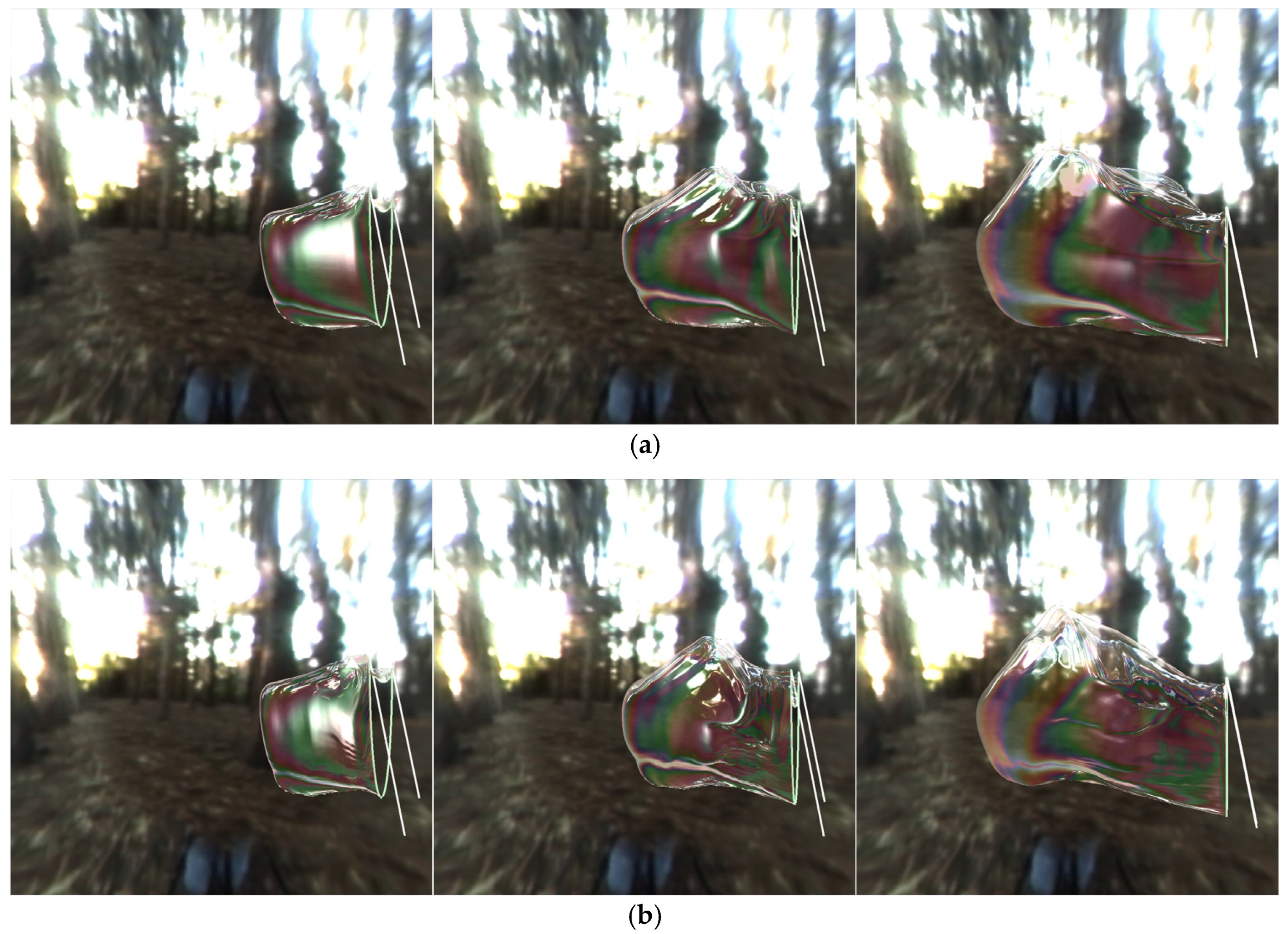
Figure 12 shows a comparison between the existing method [3] and our method. Because the existing method [3] does not consider air flow inside the bubble and applies internal pressure to the soap film, it is difficult to generate the detailed deformation and an overall flat surface is often produced. Our model controls the air flow inside the soap bubble based on an air flow transfer algorithm, in order to generate detailed deformation and standing waves. In addition, our model processes air flow transfer with negligible computational cost using the efficient operations between one-ring neighboring particles, which are directly accessible in the mass-spring system. 
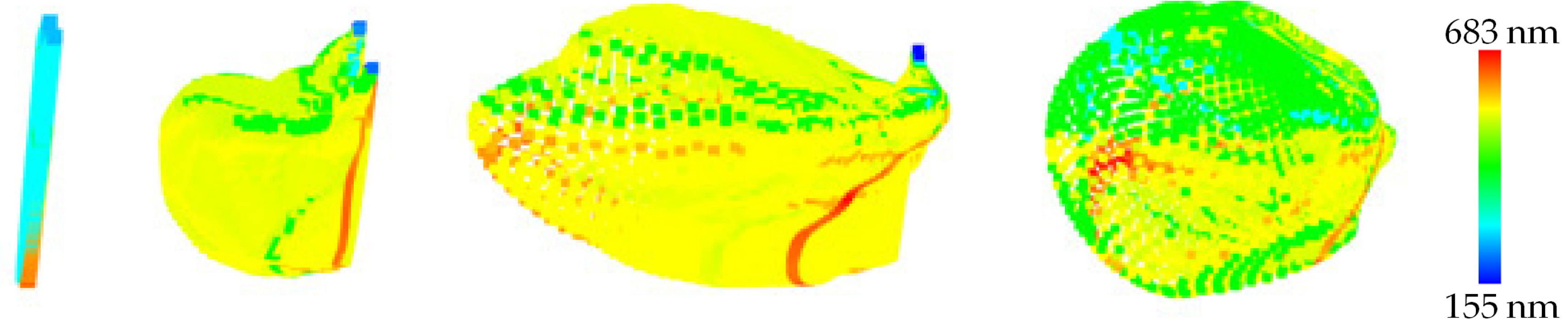
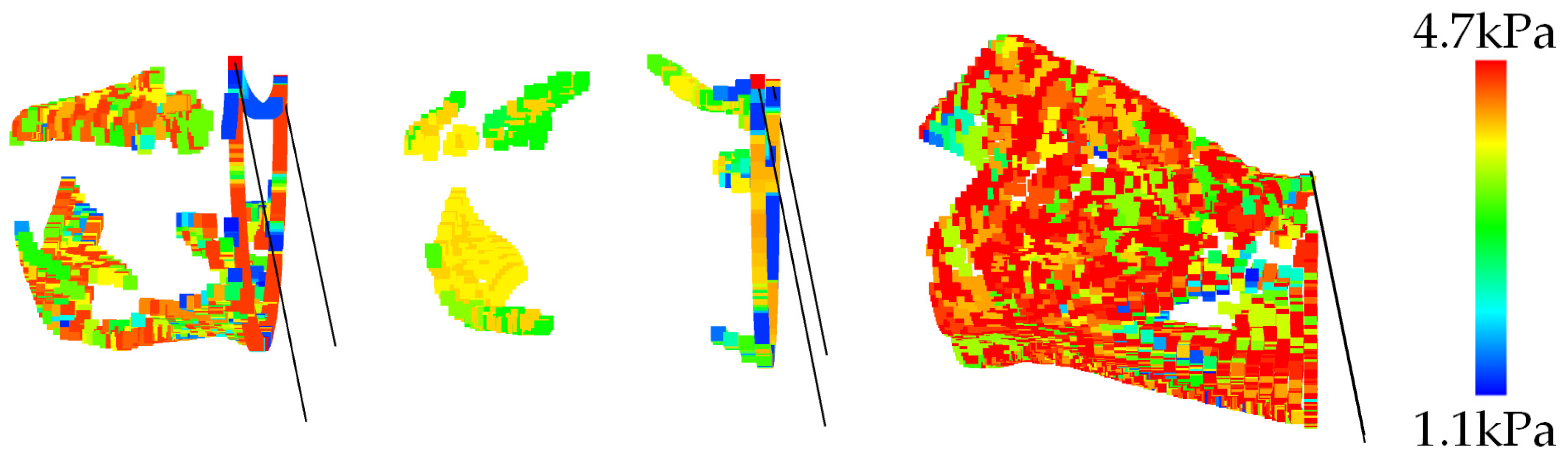
Figure 13 shows the color-coded results of Figure 12b. The blue color indicates weak air flow while the red color indicates strong air flow. When the wand moves towards the right direction, air flow moves towards the left. Air flow accumulates as the wand is moved, which shows that the intensity of the air flow is stronger than in the previous state. Table 1 shows the computation times for each result and Table 2 shows the parameters used in our system.
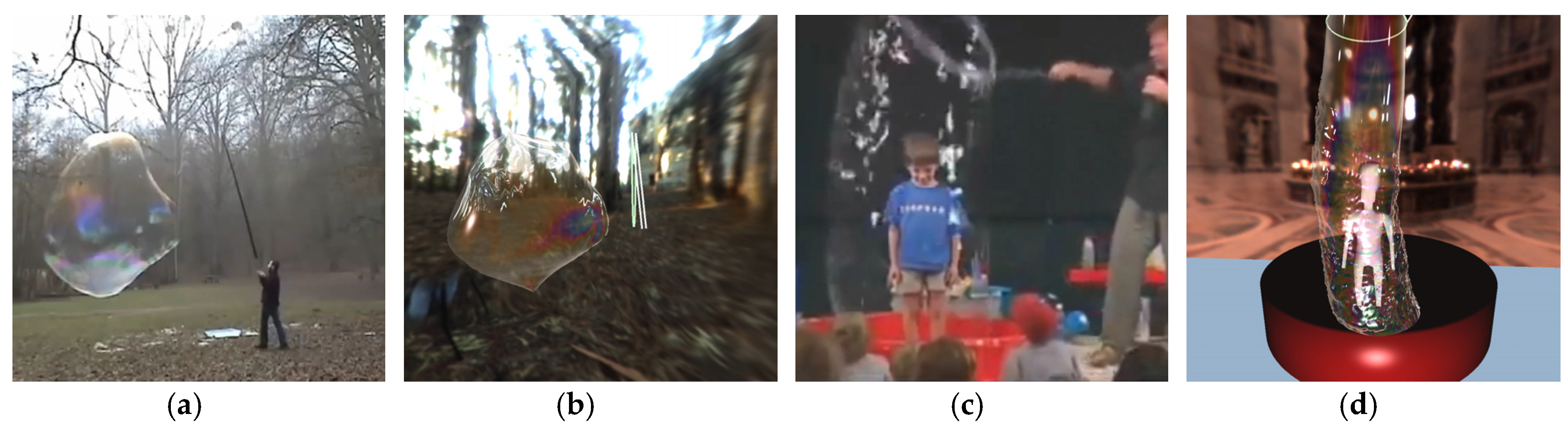
Figure 14 shows the comparisons of our simulation results with real footage. Figure 14a,b show the actual footage and simulation results, respectively, when using a tool with two wands. The simulation results show the inflation of the soap film in the left direction, opposite the direction in which the wand moves, as shown in the footage. The simulation results also show that the soap film surface is very smooth and curved as seen in the footage. Figure 14c,d show the real footage and simulation results, respectively, when creating a giant soap bubble from a soap solution using a single wand tool. The simulation results show that the soap bubble is created according to the direction in which the wand moves from bottom to top, as shown in the footage. In addition, although the new surface continues to be generated according to the motion of the wand, the simulated results show that the soap film surface is smooth and the standing wave is expressed as seen in the footage.

9. Conclusions and Future Work

We present a novel method that automatically generates realistic animated giant soap bubbles according to the user’s hand motions. Our system allows real-time control of the shape, size, and position of soap bubbles in accordance with the user’s hand trajectory, direction of motion and distance travelled. We obtain smooth and gentle wand trajectories using a smoothing method for hand motions. Our air flow transfer algorithm represents the detailed deformation and standing wave of soap film. Our soap film bursting algorithm produces the bursting effect of soap films and bubbles based on hole opening propagation and position-dependent draining in a unified framework. The proposed system can be used for physics education and media art, and enables users to experience virtual giant soap bubble blowing and bursting using the consumer level depth camera Kinect.
In future work, we intend to investigate full body capture and minimize the occlusion problem that arises with the frequent turning and twisting motion. We will also attempt to accelerate our model by parallelizing our simulation method entirely on the GPU.

Supplementary Materials

The following are available online at https://www.mdpi.com/2073-8994/9/4/56/s1, Supplemental Video S1.

Acknowledgments

This work (NRF-2016R1A2B4016239) was supported by Mid-career Researcher Program through NRF grant funded by the MEST.

Author Contributions

Namjung Kim implemented the proposed technique and performed the experiments. Namjung Kim and Kyoungju Park wrote the paper.

Conflicts of Interest

The authors declare no conflicts of interest.

References

  1. Ballet, P.; Graner, F. Giant soap curtains for public presentations. Eur. J. Phys. 2006, 27, 951–967. [Google Scholar] [CrossRef]
  2. Zhu, B.; Quigley, E.; Cong, M.; Solomon, J.; Fedkiw, R. Codimensional surface tension flow on simplicial complexes. ACM Trans. Graph. 2014, 33. [Google Scholar] [CrossRef]
  3. Kim, N.; Oh, S.; Park, K. Giant soap bubble creation model. Comput. Anim. Virtual Worlds 2015, 26, 445–455. [Google Scholar] [CrossRef]
  4. Murata, T.; Shin, L. Hand gesture and character recognition based on kinect sensor. Int. J. Distrib. Sens. Netw. 2014. [Google Scholar] [CrossRef]
  5. Yang, H.-D. Sign language recognition with the Kinect sensor based on conditional random fields. Sensors 2014, 15, 135–147. [Google Scholar] [CrossRef] [PubMed]
  6. Stone, E.E.; Skubic, M. Unobtrusive, continuous, in-home gait measurement using the microsoft kinect. IEEE Trans. Biomed. Eng. 2013, 60, 2925–2932. [Google Scholar] [CrossRef] [PubMed]
  7. Lee, S.; Park, S.; Chung, K.; Cho, C. Kinematic skeleton based control of a virtual simulator for military training. Symmetry 2015, 7, 1043–1060. [Google Scholar] [CrossRef]
  8. Choi, J.; Kim, S.; Kim, C.; Lee, J. Let’s be a virtual juggler. Comput. Anim. Virtual Worlds 2016, 27, 443–450. [Google Scholar] [CrossRef]
  9. Durikovic, R. Animation of soap bubble dynamics, cluster formation and collision. Comput. Graph. Forum 2001, 20, 67–75. [Google Scholar] [CrossRef]
  10. Wei, X.; Zhao, Y.; Fan, Z.; Li, W.; Yoakum-Stover, S.; Kaufman, A. Blowing in the wind. In Proceedings of the Symposium Computer Animation, San Diego, CA, USA, 26–27 July 2003; pp. 75–85. [Google Scholar]
  11. Huszar, T.; Szecsi, L. GPU-supported bubble and foam rendering. In Proceedings of the CESCG 2010, Budmerice, Slovakia, 10–12 May 2010; pp. 149–155. [Google Scholar]
  12. Zheng, W.; Yong, J.-H.; Paul, J.-C. Simulation of bubbles. Graph. Models 2009, 71, 229–239. [Google Scholar] [CrossRef]
  13. Pan, H.; Choi, Y.-K.; Liu, Y.; Hu, W.; Du, Q.; Polthier, K.; Zhang, C.; Wang, W. Robust modeling of constant mean curvature surfaces. ACM Trans. Graph. 2012, 31. [Google Scholar] [CrossRef]
  14. Da, F.; Batty, C.; Wojtan, C.; Grinspun, E. Double bubbles sans toil and trouble: Discrete circulation-preserving vortex sheets for soap films and foams. ACM Trans. Graph. 2015, 34. [Google Scholar] [CrossRef]
  15. Li, L.; Volkov, V. Inflatable models. J. Comput. Sci. Technol. 2006, 21, 154–158. [Google Scholar] [CrossRef]
  16. Chen, Z.; Feng, R.; Wang, H. Modeling friction and air effects between cloth and deformable bodies. ACM Trans. Graph. 2013, 32. [Google Scholar] [CrossRef]
  17. Pan, J.; Zhang, L.; Manocha, D. Fast smoothing of motion planning trajectories using b-splines. In Proceedings of the Robotics: Science and Systems, Los Angeles, CA, USA, 27–30 June 2011. [Google Scholar]
  18. Bartels, R.H.; Beatty, J.C.; Barsky, B.A. An Introduction to Splines for Use in Computer Graphics and Geometric Modeling; Morgan Kaufmann: Los Altos, CA, USA, 1986. [Google Scholar]
  19. Janabi-Sharifi, F.; Hayward, V.; Chen, C.-S.J. Discrete-time daptive windowing for velocity estimation. IEEE Trans. Control Syst. Technol. 2000, 8, 1003–1009. [Google Scholar] [CrossRef]
  20. Meyer, M.; Desbrun, M.; Schroder, P.; Barr, A. Discrete differential-geometry operators for triangulated 2-manifolds. Vis. Math. 2002, 3, 34–57. [Google Scholar]
  21. Pfaff, T.; Thuerey, N.; Gross, M. Lagrangian vortex sheets for animating fluids. ACM Trans. Graph. 2012, 31. [Google Scholar] [CrossRef]
  22. Zhang, Y.; Wang, H.; Wang, S.; Tong, Y.; Zhou, K. A deformable surface model for real-time water drop animation. IEEE Trans. Visual. Comput. Graph. 2012, 18, 1281–1289. [Google Scholar] [CrossRef] [PubMed]
  23. Li, J.; Liu, M.; Xu, W.; Liang, H.; Liu, L. Boundary-dominant flower blooming simulation. Comput. Anim. Virtual Worlds 2015, 26, 433–443. [Google Scholar] [CrossRef]
  24. Tang, W.; Wan, T.R.; Huang, D. Interactive thin elastic materials. Comput. Anim. Virtual Worlds 2016, 27, 141–150. [Google Scholar] [CrossRef]
  25. Lhuissier, H.; Villermaux, E. Bursting bubble aerosols. J. Fluid Mech. 2012, 696, 5–44. [Google Scholar] [CrossRef] [PubMed]
  26. Culick, F.E.C. Comments on a ruptured soap film. J. Appl. Phys. 1960, 31, 1128–1129. [Google Scholar] [CrossRef]
  27. Petit, P.C.; le Merrer, M.; Biance, A.-L. Holes and cracks in rigid foam films. J. Fluid Mech. 2015, 774, R3. [Google Scholar] [CrossRef]
  28. Bico, J. Cracks in bursting soap films. J. Fluid Mech. 2015, 778, 1–4. [Google Scholar] [CrossRef]
  29. O’Rourke, J. Computational Geometry in C; Cambridge University Press: Cambridge, UK, 1998. [Google Scholar]
  30. Tang, M.; Manocha, D.; Tong, R. Fast continuous collision detection using deforming non-penetration filters. In Proceedings of the Symposium Interactive 3D Graphics and Games, Bethesda, MD, USA, 19–21 February 2010; pp. 7–13. [Google Scholar]
Figure 1. Photographs of a real giant soap bubble blowing and bursting. When using a tool with (a) two wands and (b) single wand.
Symmetry 09 00056 g001
Figure 2. The system pipeline of the proposed method.
Symmetry 09 00056 g002
Figure 3. Proposed system configuration diagram.
Symmetry 09 00056 g003
Figure 4. (a) Input hand trajectories; (b) interpolated hand trajectories; and (c) wand trajectories. Left hand (red curve), right hand (blue curve).
Symmetry 09 00056 g004
Figure 5. Schematic diagram of the air inflow.
Symmetry 09 00056 g005
Figure 6. Schematic diagram of air flow transfer (starting with the end particles of the soap film, air is introduced into the adjoining soap film particles).
Symmetry 09 00056 g006
Figure 7. Conceptual diagram of soap film bursting.
Symmetry 09 00056 g007
Figure 8. Draining results. Blue color represents thin regions, red color represents thick regions.
Symmetry 09 00056 g008
Figure 9. Results by the amount of remaining soap solution: (a) 1.0; (b) 0.75; and (c) 0.5.
Symmetry 09 00056 g009
Figure 10. Simulation results (left), left wand trajectory (middle), right wand trajectory (right). Input hand trajectory (dotted line), wand trajectory (full line), starting point (+), end point (×), current point (square). When the user's hands movements are gentle (ac). When user's hands movements are sudden (df).
Symmetry 09 00056 g010aSymmetry 09 00056 g010b
Figure 11. Simulation results by our soap film bursting method. (a) When using a tool with two wands; and (b) when using a tool with single wand.
Symmetry 09 00056 g011aSymmetry 09 00056 g011b
Figure 12. Comparison of air effects. (a) Existing method [3]; and (b) our method.
Symmetry 09 00056 g012
Figure 13. Results of the color coding of the strength of the air flow in Figure 12b.
Symmetry 09 00056 g013
Figure 14. Comparison of simulation results and real footage. (a) The real footage and (b) simulation result, respectively, when using a tool with two wands. (c) The real footage and (d) simulation result, respectively, when using a tool with single wand.
Symmetry 09 00056 g014
Table 1. The computation times (frames per second) for each result.
ExampleAvg. Particle SizeAvg. Triangle SizeAvg. Time (fps) (Including Rendering)
Figure 10a945215,32431.2
Figure 10b908812,54235.0
Figure 10c986821,03628.5
Figure 10d925214,28231.3
Figure 10e16,02032,56820.1
Figure 10f13,88228,32422.5
Figure 11a13,05628,11223.1
Figure 11b25,65041,20818.1
Figure 12a10,02620,32826.5
Figure 12b11,32823,58027.3
Table 2. Parameters used in our system.
NotationParameter NameRange
w E Varying elasticity coefficient (Section 5.1)[12.0~13.0]
w e Area weight (Section 5.1)[0.02~0.05]
λ a i r Air direction threshold (Section 5.2.2)[0.5~0.7]
h Time step (Section 5.3)0.02
λ t h i Thickness threshold (Section 6.1)[20~50]
S t i c k y Viscosity of the soap solution (Section 6.2)[20.0~30.0]
λ c o l Colliding threshold (Section 8)[1.5~2.0]

