Article

Computer-Aided Panoramic Images Enriched by Shadow Construction on a Prism and Pyramid Polyhedral Surface

by
Jolanta Dzwierzynska
Department of Architectural Design and Engineering Graphics, Rzeszow University of Technology, Powstancow Warszawy 12, 35-959 Rzeszow, Poland
Symmetry 2017, 9(10), 214; https://doi.org/10.3390/sym9100214
Submission received: 1 August 2017 / Revised: 7 September 2017 / Accepted: 24 September 2017 / Published: 3 October 2017
(This article belongs to the Special Issue Polyhedral Structures)

Abstract

:
The aim of this study is to develop an efficient and practical method of a direct mapping of a panoramic projection on an unfolded prism and pyramid polyhedral projection surface with the aid of a computer. Due to the fact that straight lines very often appear in any architectural form we formulate algorithms which utilize data about lines and draw panoramas as plots of functions in Mathcad software. The ability to draw panoramic images of lines enables drawing a wireframe image of an architectural object. The application of the multicenter projection, as well as the idea of shadow construction in the panoramic representation, aims at achieving a panoramic image close to human perception. The algorithms are universal as the application of changeable base elements of panoramic projection—horizon height, station point location, number of polyhedral walls—enables drawing panoramic images from various viewing positions. However, for more efficient and easier drawing, the algorithms should be implemented in some graphical package. The representation presented in the paper and the method of its direct mapping on a flat unfolded projection surface can find application in the presentation of architectural spaces in advertising and art when drawings are displayed on polyhedral surfaces and can be observed from multiple viewing positions.

1. Introduction

Transforming the reality of the visual world into a flat picture plane has been a challenging task since the early years of architectural design. Perspective as a visual representation of space from a specific view point has become the most popular method throughout a wide variety of fields. However, understanding the concept of perspective, and the approach to it, has changed over the years. The techniques of pictorial perspective were discussed by painters as part of a growing interest in skenographia as long ago as in the fifth century BC [1]. The Greeks and Romans understood perspective and utilized foreshortening techniques in art, but over time, their knowledge was lost. Perspective regarded as a practical method of drawing a scene captured by an artist was rediscovered again and investigated during the Renaissance [2,3,4]. Then, it developed itself as a kind of science of vision encompassing the nature of functioning of a human eye, as well as the nature and behavior of light. However, only the creation of descriptive geometry as a branch of mathematics in the seventeenth century enabled further development of the theory of perspective as a method of projection, which enabled its comprehensive research [5,6]. A historical evolution of the perspective projection, as well as the perception of architecture in this projection, is presented in [7]. Perspective drawing as a result of the perspective representation is widely discussed as a medium for design and communication in architecture both during preliminary architectural work and at an advanced stage [8,9,10].
Research on perspective concentrates mostly on a descriptive, as well as a computer-aided, construction of linear perspective. Today, modern graphics software can create and demonstrate various perspective representations, as well as steer and control them. There exists abundant research in this field. Investigation of the processing of linear perspective and binocular information for the perceptual judgment of depth is discussed in [11,12]. Different projection transformations defining various perspective representations are presented in [12]. The kind of perspective, determining different outcomes of the perspective projection, depends both on structure of a perspective apparatus and object location. In turn, the structure of the perspective apparatus determined by a picture plane/a picture surface and a station point/camera orientation, defines the variant of perspective applied (rectilinear or curvilinear). However, the object location establishes the number of vanishing points of three main object directions x, y, z. Due to this fact, the most common categorizations of artificial perspective onto a flat projection plane are one-, two-, and three-point, which refers to the number of vanishing points applied. Establishing vanishing points plays an important role not only in perspective creation but also in the reverse process that is the reconstruction of perspective [13,14]. Therefore, several works deal with automatic detection of the vanishing points in monoscopic image, which is the first step to three dimensional data extraction [15,16,17]. Much work has been done in the field of perspective analyses and perspective construction of the architectural environment onto a single flat projection plane [2,3,4,5,6]. There is also a great interest in the curvilinear type of perspective, especially in various methods of panorama creation on cylindrical, as well as spherical, surfaces [18]. The idea of the perspective construction onto a non-regular prism surface composed of several flat elements is presented in [19]. There, the descriptive method of drawing perspective on an unfolded prism projection surface is presented, as well as the approach to drawing this perspective with computer aid. In this paper, we develop this idea and present an effective and practical method of constructing a panoramic projection of the polyhedral architectural form onto both prism and pyramid projection surface, which is inscribed properly in a cylindrical or conical surface. In order to achieve panoramic images close to human perception, we develop the idea of perspective creation from the center moving on a circular path. Such an approach was presented in the case of constructing the classical panorama onto a cylindrical surface and in the case of an inverse cylindrical panorama where the centers of projection were dispersed on a circle or on a straight line [20,21]. In the paper we develop effective algorithms, which allow us to draw, with computer aid, a panoramic image on an unfolded regular prism, as well as on a pyramid surface. Moreover, due to the fact that very often the panoramic representation of the architectural form is enriched by shadow construction, we address the problem of natural shadow construction in perspective onto a polyhedral projection surface; in particular, we develop the idea of shadow contour determination in the panoramic image on a regular prism and pyramid polyhedral surface.
Shadows play a very important role in generating an impression of three-dimensionality of the two-dimensional image, as they enhance our perception of space. However, perspective construction of natural (solar) shadows is one of the most complex geometric constructions due to many possible arrangements of a light source, shadow casting edges, as well as a shadow-receiving surface in relation to the viewpoint. The basic rules of constructing shadows have been widely discussed in multiple publications by famous thinkers since the Renaissance. Nowadays, they are mostly considered in the context of soft and hard shadows for computer graphics. In our approach we concentrate on the geometrical aspects of cast and attached shadows. We construct shadow lines in the axonometric view or orthographic views according to the rules of shadow constructing [22]. Shadow lines establish the border between a cast shadow and an illuminated area which is next represented onto the polyhedral surface.

2. General Aspects of Shadow Construction

The invention of linear perspective, as well as developments in utilization of light and shadows, revolutionized visual arts and architecture in the Renaissance. Light was, and still is, a tool that artists use to define their subject matters and to add a certain sense of realism to the picture. Therefore, to the artists and art theorists of the Renaissance, the proper depiction of shadows was of great interest. Their works explored the contrasts between light and darkness. This technique of tonal contrasting between light and darkness, called chiaroscuro, demonstrated the skill of an artist in the management of shadows to create a three-dimensional effect in a painting [23,24]. Leonardo da Vinci is regarded as one of the pioneers in research on light and shadow [25]. His research embraced not only a geometric approach to shadow creation, but also optical aspects of it as he provided one of the very first studies of penumbra—the area which receives partial light from the source during lighting. This term was coined and investigated further by Kepler [26].
Shadows vary greatly as a function of the lighting environment. The main factor which determines the shadow’s appearance and shape is the type of light source applied: artificial or natural. Shadows can appear as hard-edged or soft-edged and can contain both the umbra and penumbra area. The relative size of the umbra-penumbra is a function of the size and shape of the light source, as well as its distance from the object. The definition of the penumbra rate as well as its significance and application in architecture is discussed in [27]. The work shows future possibilities of incorporating penumbra zones into the architectural design process.
Today, graphics software make it possible to accurately render shadows from a point and directional light sources in various interactive applications. There are several different approaches to rendering shadows with computer aid. The most popular approaches to define shadow regions are: the planar projected shadows approach, an approach which uses shadow volume and shadow maps approach, as well as a combination of them. A planar projected shadow approach is an extremely simple method of generating shadows onto planar surface. The method simply involves drawing the projection of the given object onto a plane. The shadow volume approach deals with objects of polygonal structure. It consists in generating shadows by creating for each object a shadow volume that the object blocks from the light source. It assumes that any object located in the shadow volume is in shadow. This infinite shadow volume is defined by lines emanating from the light source through vertices of the object. The basic idea of the shadow map construction is that the object is in shadow if it is not visible to the light [28].
Our approach to shadow construction is similar to the planar projected shadows approach. In our considerations we concentrate on shadows formed by the natural light. In this case light appears to emanate as straight line rays from the surface area of the light source—the sun. Due to the fact that the light source is at infinity, the light rays are parallel. The angular size of the sun is relatively small and constant, while the majority of shadow casting objects are close to the ground. Therefore, the penumbra, that is, the fuzzy boundaries between shadowed regions and fully-illuminated regions, can be ignored in the perspective image [23]. This also implies a simplification of the construction of shadows in perspective to the geometry of the shadow casting object, the viewer’s location, as well as the surface’s geometry on which the shadow is casted. In such geometrical terms the edges of the shadows are sharp and clearly defined as boundary lines circumscribed by light rays. Due to this fact they can be determined by geometric methods and rules. However, these rules can be applied when the shadows are viewed from a distance, that is both the object and its shadow are within a 60° circle of view.

3. Geometrical Aspects of Panoramic Projection onto a Polyhedral Surface

According to its descriptive geometry definition, perspective is a central projection from a real point onto a projection plane/surface, and it is subjected to projective geometry rules. The most common type of perspective which finds application is a vertical linear perspective onto two dimensional plane. It creates an illusion of depth by use of so-called ‘vanishing points’ to which all parallel lines converge at the level of horizon, which is the eye level. The base elements which determine this kind of perspective are a picture plane, a station point, and a base plane, while invariants of this perspective projection are incidence, collinearity of three non-coinciding points, and division of line segment parallel to the projection plane [22].
In our considerations we take into account panoramic projection, namely wide view perspective onto the projection surface being a regular polyhedral surface that is the surface composed of the several similar flat walls. Due to this fact, the above invariants of perspective projection onto a flat picture plane can find application for each separate polyhedral wall.
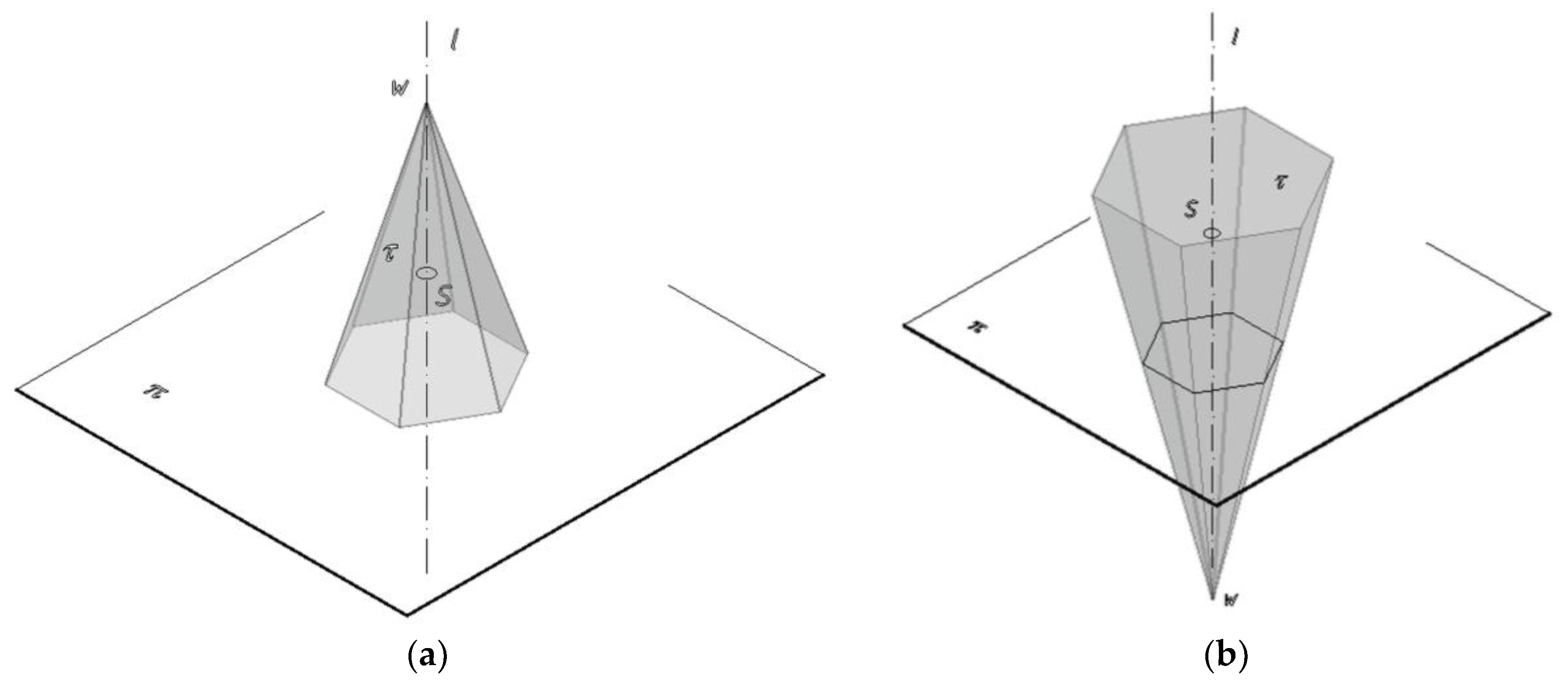
According to our assumptions, the projection apparatus in this case is received from an apparatus of a cylindrical or conical panoramic projection by replacing the cylindrical/conical surface with the regular polyhedral surface inscribed in it. Due to this fact, the apparatus of the considered representation is composed of a polyhedral projection surface τ, a viewpoint S/SX and a base plane πτ. The center of projection can be a single stationary point S belonging to the axis l or a point SX moving on the circular path s included in a horizon plane (Figure 1).
In the case of the panoramic projection onto pyramid polyhedral projection surface two variants of the projection apparatus structure can be distinguished depending on the location of the surface’s vertex W towards the base plane π: above, variant A; below, variant B (Figure 2).
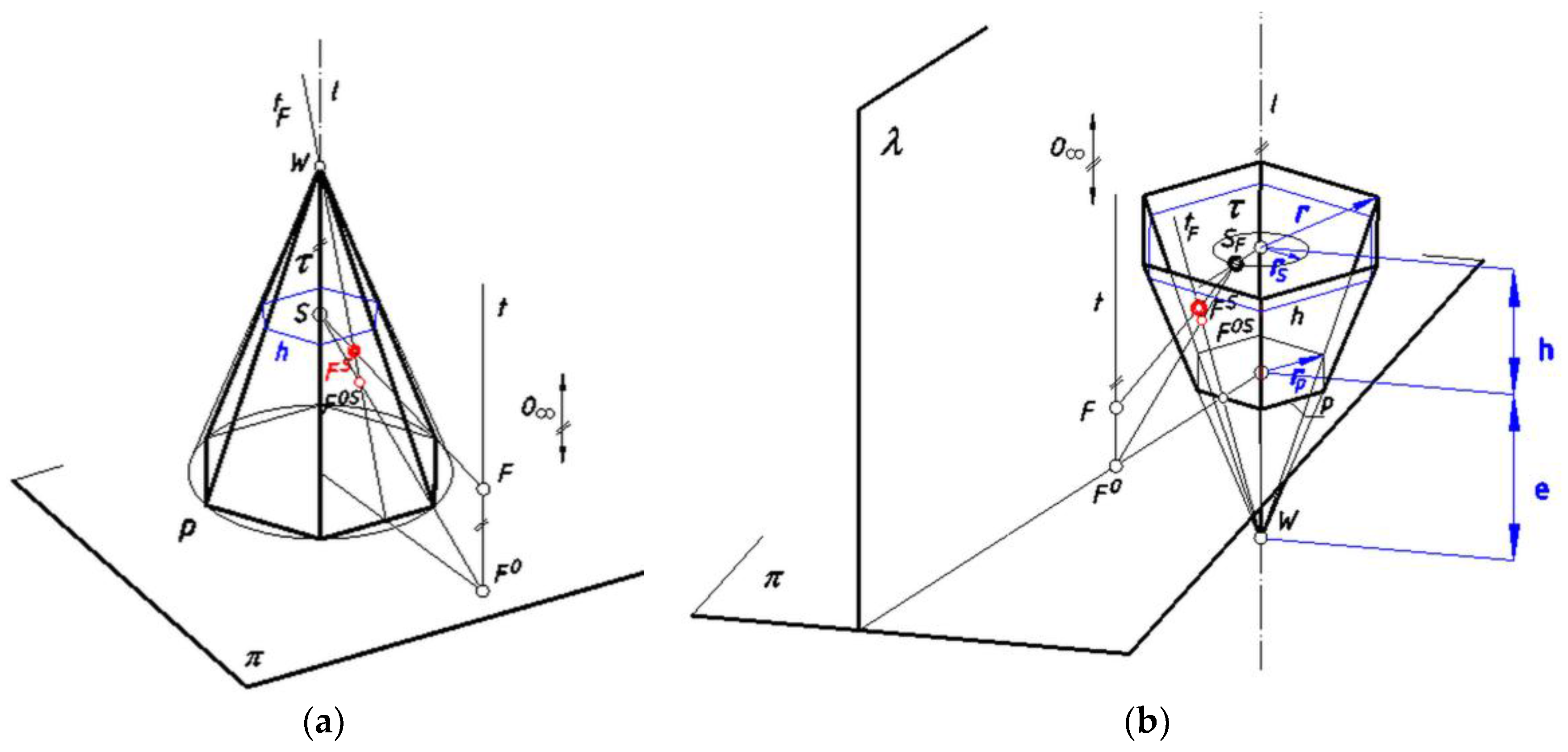
Defining the apparatus of perspective projection in this way, a perspective image of any proper point F is a pair of two points (FS, FOS), Figure 3. The point FS is a central projection of F onto τ from S/SF, whereas FOS is a central projection of FO (orthogonal projection of F onto a base plane π) onto τ. Both points FS and FOS are included in the same generatrix line tF which goes through a vertex W/W∞ and through a point of a base polygon p. The point FS is the main projection, whereas the point FOS is an auxiliary projection enabling restitution. A changeable center SF of panoramic projection is attributed to the given real point F by cutting the circle s by half-plane λ determined by the edge l and the point F (see Figure 3). The generatrix line tF is also the main projection of a vertical line t from S/SF onto τ.
In the considered panoramic projection, we represent all points which are situated behind the projection surface that is all points located on the other side of the projection surface than the center of projection S and the points which are situated on the base plane π or above it.

4. Mapping Polyhedral Panorama Directly on an Unfolded Projection Surface

Due to the fact that each polyhedral surface can be unfolded on a plane, it is convenient to present the images of our panoramic representation on a flat unfolded surface. In order to do that, we transform the images contained in the projection surface τ into their counterparts included in the unfolded surface τR. Such a transformation is realized by projecting each generatrix line tX of the polyhedral surface τ from the center S/SX onto the base plane π. Then, it is possible to establish projective relations between the points on the generatrix lines of this degenerate flat surface obtained as a result of projection and their counterparts on the generatrix lines contained on the unfolded surface. A similar approach is presented in [20], where the construction of a cylindrical panorama is presented as well in [29], where construction of a conical panorama is shown.

Establishing Equations Displaying Geometrical Relations Occurring during Projection

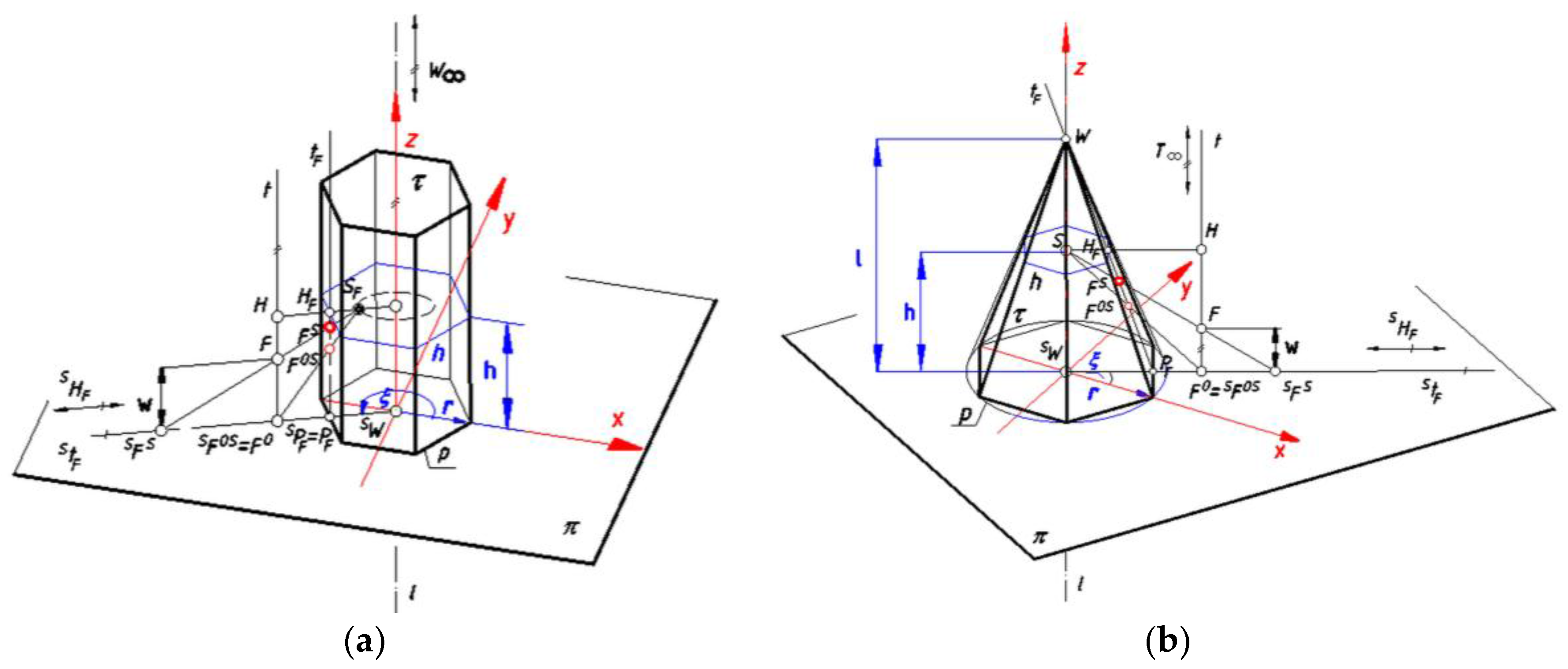
Let us consider a central projection StF of a generatrix line tF (included in a prism/pyramid projection surface) from a center S/SF onto a base plane π (Figure 4).
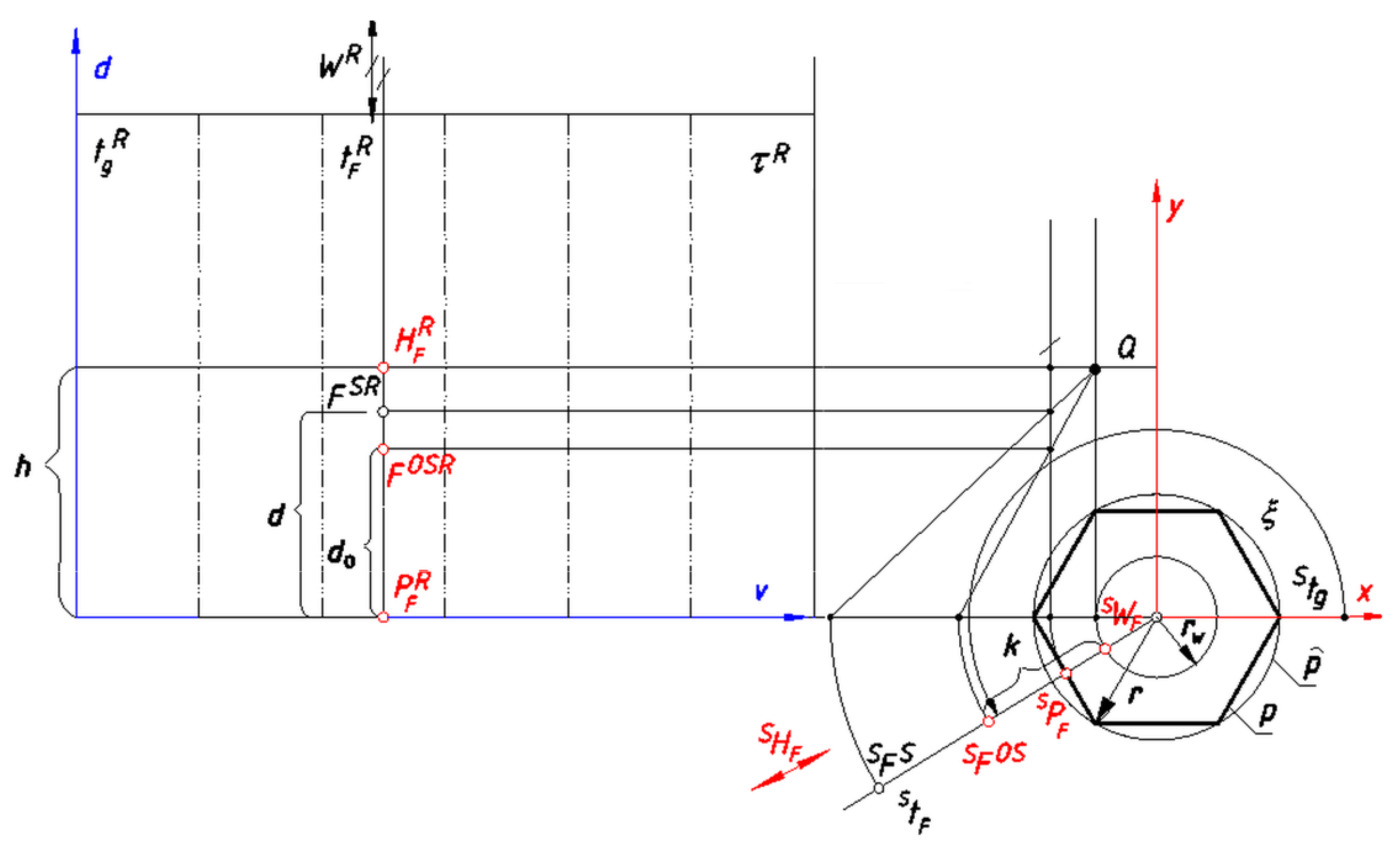
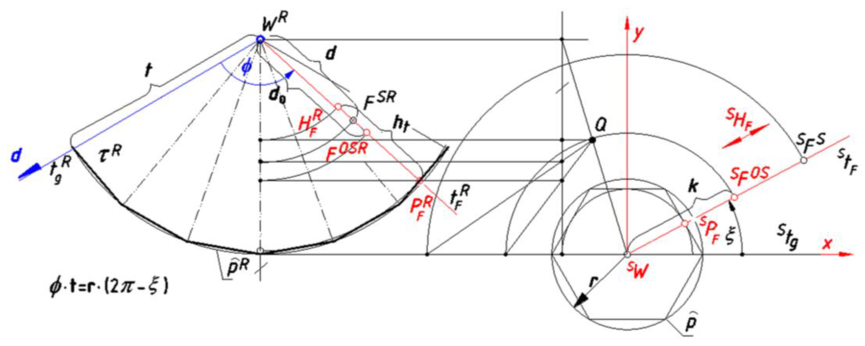
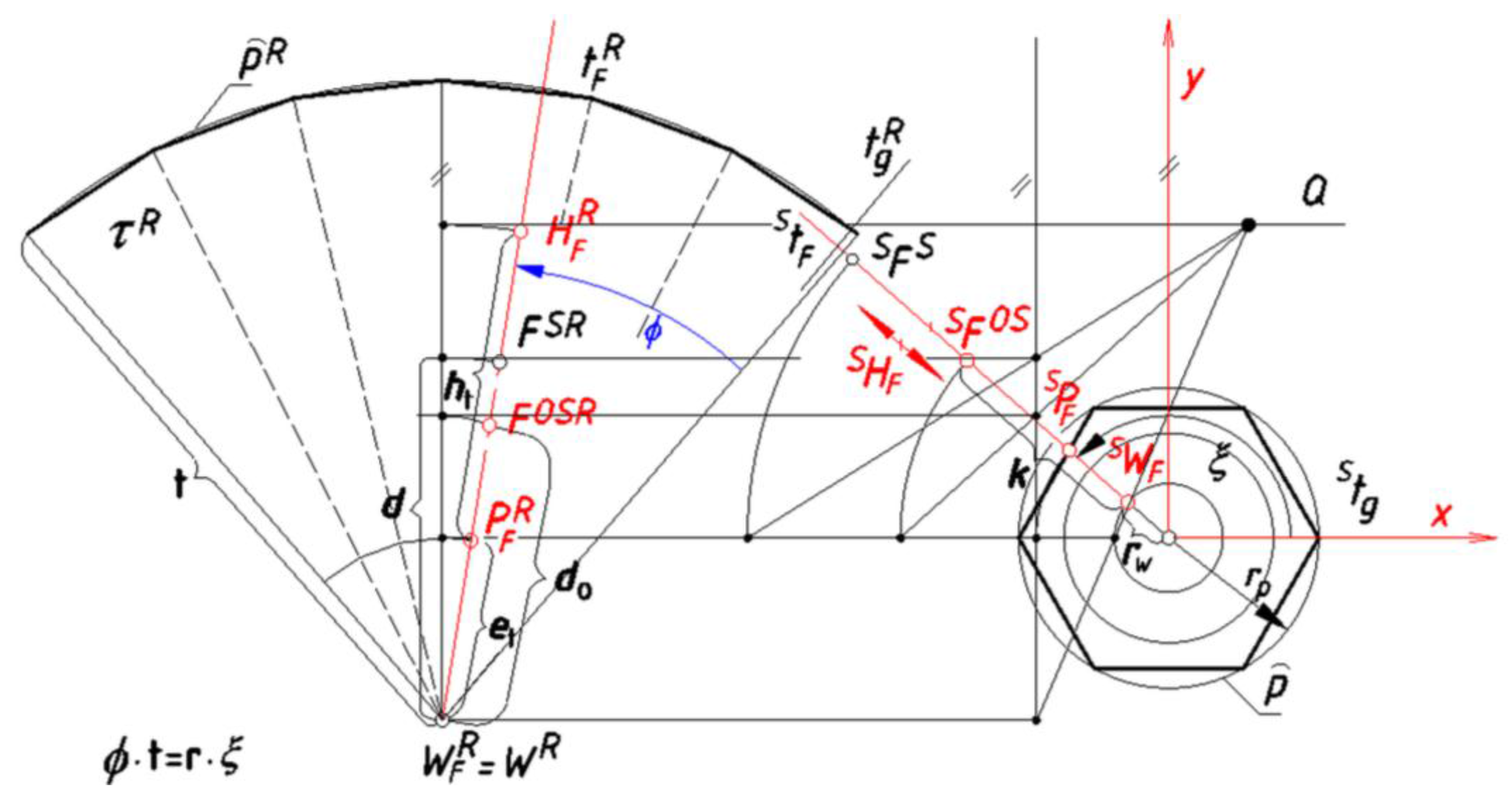
We distinguish four characteristic points included in a generatrix line tF: W∞/W, PF, FO,S, and HF, where a point PF is included in the base polygon p, a point HF is included in the horizon polygon, and a point W∞/W is a vertex of the projection surface—a point at infinity or a real point (see Figure 4). After the central projection of tF from S/SF onto π we respectively receive range of points: SWF, SPF, SFO,S, and SHF included in the line StF, (see Figure 4). The considered range of points included in StF and the range of points contained in a generatrix tF are homologous. Additionally, the range of points SPF, SHF, SWF, and SFO,S on the line StF, and the range of points PFR, HFR, WR, and FO,SR on the line tFR contained in the unfolded surface τR are related by the projective transformation. This transformation for a prism projection surface is expressed in the graphical way in Figure 5. The transformation, in the case of a pyramid projection surface for both versions A and B, is presented properly in Figure 6 and Figure 7. The mentioned above graphical connection enables drawing a panoramic image FSR of a point F when its projection SFS is given. It is worth nothing that for any point Fπ, SFS = SFO,S = F, which simplifies the construction.
Due to above projective relations, the cross ratio of the quadruple of range points on the line StF as well as the cross ratio of the quadruple of proper range points on a line tFR is preserved during transformation, which can be expressed as follows:
F O , S S P F S W F S P F S ÷ F O , S S H F S W F S H F S = F O , S R P F R W R P F R ÷ F O , S R H F W R H F R
Similarly, the range of points on a vertical line t and a proper range of points on a line tF are homologues, Figure 4. Therefore:
F O H F H ÷ F O T F T = F O , S H F F S H F ÷ F O , S W F S W
where W in the equations can be a real point or a point at infinity.
We determine, (see Figure 4, Figure 5, Figure 6 and Figure 7):
  • the distance of the point SFO,S = FO from the point SW by k;
  • the distance of the point FO,SR from the point PFR by do, if the case of the projection on a prism surface;
  • the distance of the point FO,SR from the point WR by do, if the case of the projection on a pyramid surface;
  • the distance of the point FSR from the point PFR by d, if the case of the projection on a prism surface;
  • the distance of the point FSR from the point WR by d, if the case of the projection on a pyramid surface;
  • the distance of the point HFR from the point PFR by ht;
  • the distance of the point PFR from the point WR by t;
  • the distance of the point PF from the point W by et;
  • the distance of the point PF from the point SWF by rp, if the case of the projection on a pyramid surface of version B;
  • the distance of the point SWF from the center of the base polygon p by rw.
According to Figure 5, Figure 6 and Figure 7 and the equations (1) and (2), we derive formulas:
d o = h × ( k r ) k r S
d = ( w h ) × ( h d o ) h + h
in the case of a prism projection surface,
d o = t × ( t h t ) × ( k r w ) h t × ( r w r ) + t × ( k r w )
d = h × ( d o r s × t r ) × ( t h t ) + r s × t r × ( h w ) × ( h t + t d o ) h × ( d o r s × t r ) + ( h w ) × ( t d o h t )
in the case of a pyramid surface of version A,
d o = e t × ( h t + e t ) × ( k r w ) h t × ( k r p ) ( h t + e t ) × ( k r w )
d = h × ( h t + e t ) × ( d o r s × t r ) + r s × t r × ( h w ) × ( h t + e t d o ) ( h w ) × ( h t + e t d o ) + h × ( d o r s × t r )
in the case of a pyramid surface of version B.
In the above equations the value of r and rp change according to base polygon geometry and value of ξ. We apply the same formulas for both panoramic projection from a single center and for multicenter projection. In the case of the application of the stationary view point the radius of the circle of viewpoints rs equals zero.

5. Drawing Perspective with Computer Aid

5.1. Methods and Methodology

The projective relations expressed above enable the creation of the panoramic representations on prism and pyramid surfaces with computer aid. Usually computer programs for drawing perspective representations use linear algebra, in particular matrix multiplication to describe transformations of point coordinates of a model to the point coordinates on a screen [30,31].
However, compared to other panorama construction methods that use information about points for computer vision and the CAD system, it is more convenient for us to utilize data about lines, which apply very often in architectural forms. Due to this fact, we place Cartesian coordinate system of axis x, y, z in such a way that x and y are included in the base plane π and z overlaps with an axis l. Next, using the equations derived in section four, we create analytical algorithms for drawing a panoramic image of a line AB passing through two different points A(xa,ya,za) and B(xb,yb,zb) given by their spatial coordinates in the system x, y, z. The image is created directly on the unfolded polyhedral surface τR. In the case of the panorama on a prism projection surface, the panoramic image is drawn as a plot of function d(v) in the Cartesian coordinate system of axis d, v, placed as it is shown in Figure 5. For a given point F ∈ AB a coordinate v is the distance measured on the unfolded surface between the border generatrix tgR and the generatrix tFR containing the panoramic image FSR of this point (see Figure 5). In the case of a panoramic projection onto a pyramid projection surface, the line is drawn as a plot of function d(Φ) in the polar coordinate system. For a given point F ∈ AB an angular coordinate Φ is the angle between the border generatrix tgR and the generatrix tFR containing a panoramic image FSR (Figure 6 and Figure 7). The vertex WR contained in the unfolded surface is chosen as a pole, whereas the border ruling tgR is taken as a polar axis. In both cases of panoramic projection onto prism and pyramid surfaces, it is convenient to establish the ruling tg as a border ruling, which projection Stg onto π is included in axis x (see Figure 6 and Figure 7). Both variables v and Φ occurring respectively in the functions d(v) and d(Φ) are dependent on ξ— the angle between Stg and StF measured on π (see Figure 5, Figure 6 and Figure 7). The basis for creating our algorithms to draw polyhedral panoramas were the algorithms for drawing cylindrical and conical panoramas applied in [20,21]. In our approach we treat panorama onto a prism/pyramid surface as the panorama onto a cylindrical/conical surface with a changeable radius ra of the base circle pr—the circumcircle of the base polygon p included in π (Figure 8).
For each regular polygon is as follows, Figure 8:
r a = a sin γ sin ( α α a ) + sin α a
Due to the fact that ra changes periodically dependently on the value of ξ, the algorithms for drawing a panoramic image of a straight line onto polyhedral surface are much more complicated than the ones for drawing panoramas on cylindrical and conical surfaces.
In order to draw a panoramic image of the segment AB of a straight line on a prism/pyramid surface, the range of function’s d(v)/d(Φ) arguments needs to be specified in advance. The ability to draw panoramic images of line segments make it possible to draw an edge image of an architectural object, provided that the coordinates of its vertices are known.

5.2. Results—Some Examples of the Application of the Algorithms

The starting point for any computer aided construction of a panoramic image is establishment of the base elements of panoramic projection, as well as the location of the represented object. The base elements of panoramic projection determined by the structure of the projection apparatus are: radius r of the base circle which circumscribes the base polygon p, number of vertices of the base polygon, height of horizon h and radius of the circle of viewpoints rS, in the case of multicenter projection. For the panoramic projection onto pyramid projection surface also the location of the surface’s vertex is necessary. As far as the location of represented object is concerned, it should be located in a cone of good vision during the cone’s rotation around the axis l. Let us show some examples of the algorithms’ application for drawing panoramic images of a simple building form, Figure 9.
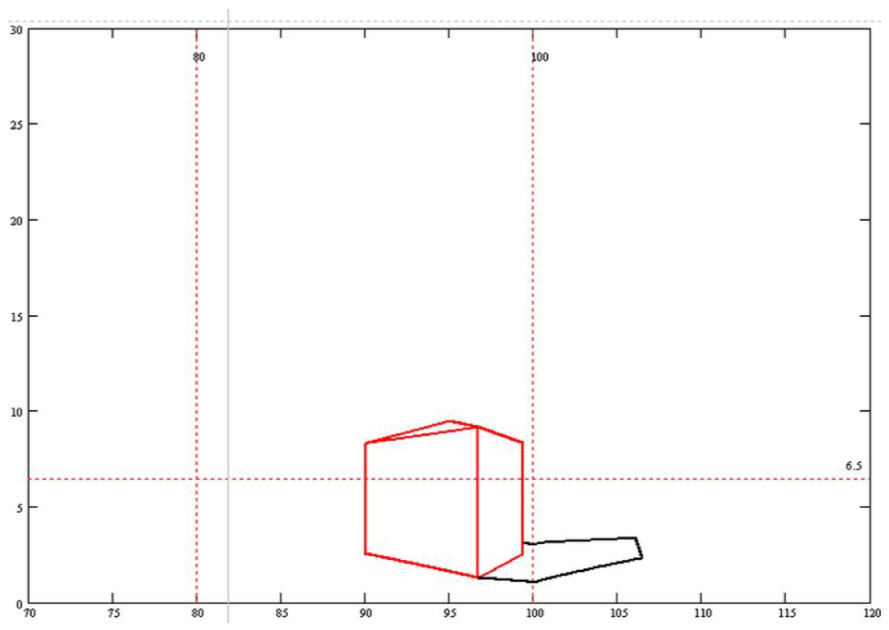
The above figure shows panoramic projections of the same building onto a prism surface from various viewing positions, however, with the same direction of light rays. This is a single center projection onto a regular six-wall prism projection surface and, respectively, with horizon height equal to 6 m and 15 m. The radius of the circumcircle of the base polygon is equal to 20 m, whereas the building height equals 12 m. The multicenter panoramic representation onto a prism projection surface is presented in Figure 10. This is the projection of the same building but with different viewer’s location, as well as with a different direction of the sun rays than in the previous case. In the presented image, we can notice changes in the panoramic view of the shadow’s border due to projection onto various prism walls.
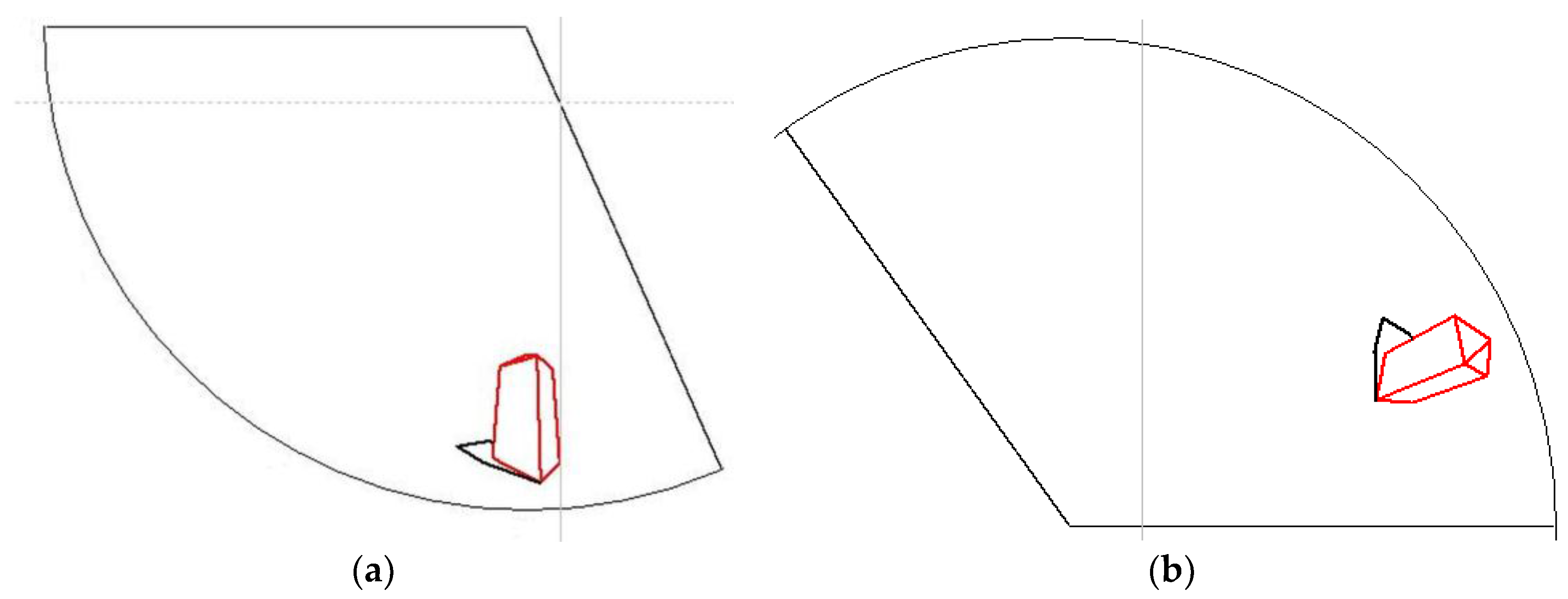
A single center panoramic projection onto a regular six wall pyramid polyhedron surface inscribed in a cylindrical surface with the radius of the base circle of 20 m is shown in Figure 11. Considering the most convenient viewing direction (perpendicular to a projection surface) it is recommended to apply the version A of the projection apparatus for frog’s eye view images, whereas the version B for bird’s eye view images.
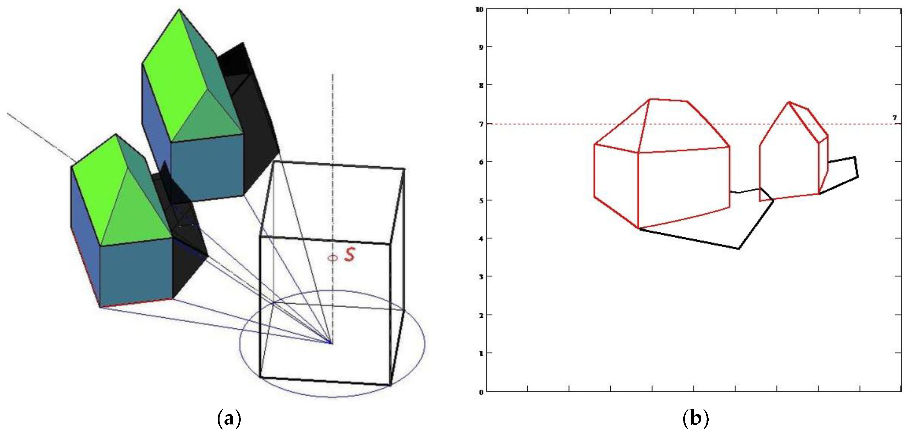
The representation of a building’s cast shadow on the ground in panoramic image requires preliminary determination of the shadow border line on the base plane, which is then treated as any flat object during projection. The issue starts to be more complicated if we need to represent a complex object or several objects located in such a way that intrinsic shadows need to be considered. It is possible to generate the border of the intrinsic shadows in Mathcad software, too, as it is shown in Figure 12.
However, due to the fact that sometimes shadow generation in Mathcad requires prior complicated construction of a shadow border line, it is much more convenient to realize shadow construction directly in the panoramic view on the unfolded projection surface. It can be done with computer aid of AutoCAD. In this case, we can base our analysis on the graphical connections between any point contained in the base plane π and its panoramic image on the unfolded projection surface presented in Section 4. These connections are especially useful to establish starting assumptions for drawing perspective. Due to this fact, in order to draw a panoramic image of a buildings’ layout presented in the Figure 12, it is first necessary to draw an orthogonal projection onto π of both buildings and a projection surface, as well as to place an unfolded projection surface τR on π as it is shown in Figure 13.
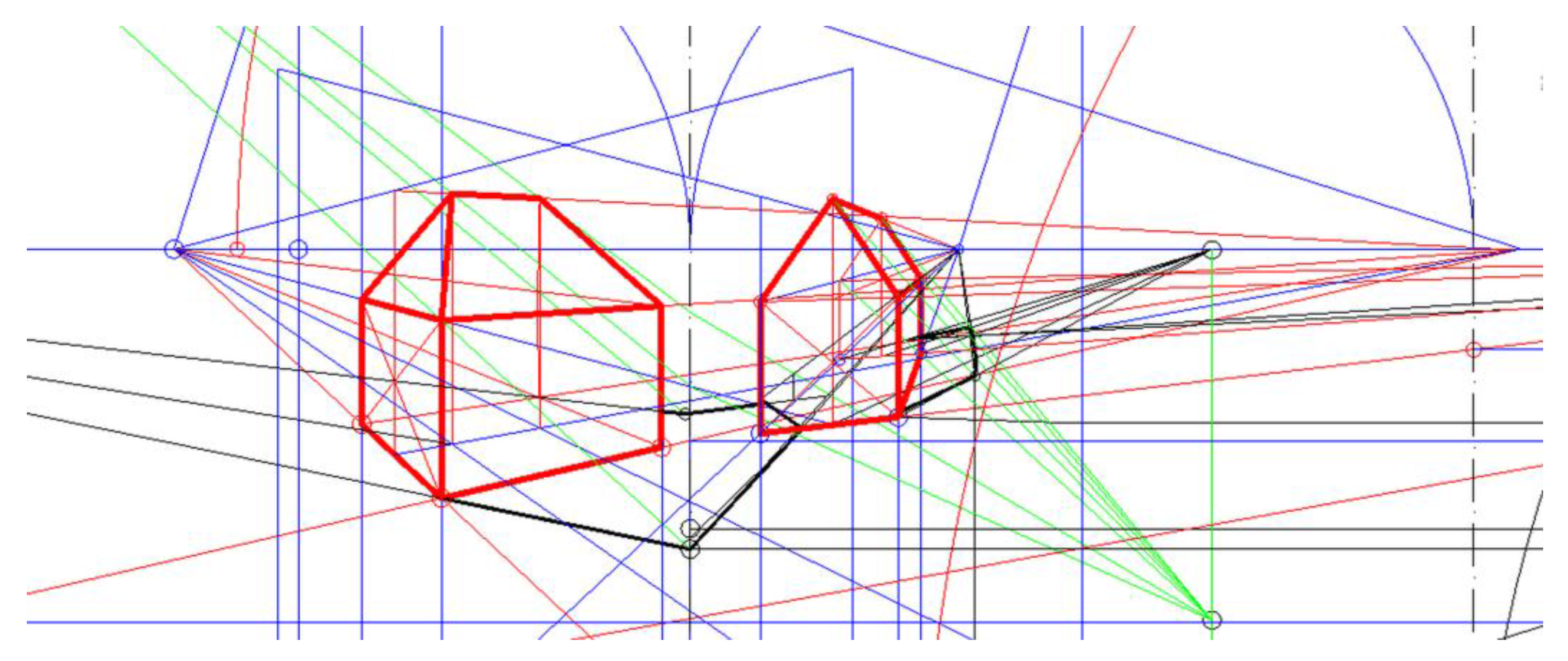
Similarly as in other perspective representations, our starting assumptions for drawing a panoramic image are two edges AB and CD of one building, which are mutually perpendicular and included in π, whereas for shadows construction it is a cast shadow line AT of one building vertical edge. The central projection of a straight line a, which contains the edge AB, is an angular line as. The end points of this angular line are included in a horizon line h, whereas its vertices are included in polyhedral edges. However, due to the fact that panoramic images of both edges AB and AC are contained in the same polyhedral wall, due to the building’s location, the drawing can be supported by a classical linear perspective construction onto a single plane. The image of the second building is located in the next polyhedral wall. The most complicated construction is the shadow construction, which enables the establishment of various vanishing points of light rays and shadow lines for each polyhedral wall. Moreover, the shadow’s border line changes its shape due to projection on the various walls. The result of the panorama construction is presented in Figure 14.
Figure 14 shows the mapping of a single center projection onto regular four-wall prism surface of the buildings presented in Figure 12a. The horizon height equals 7 m, similarly as in the previous representation by Mathcad, therefore, the results presented in Figure 12b and Figure 14 can be compared. Due to limitations of the number of plots which can be created in Mathcad for one drawing, the algorithms’ work have been tested only on the simple examples of model buildings. However, the tests showed that the algorithms work well and can be implemented in other graphical package such as for example AutoCAD.

6. Discussion

In this paper, we proposed the method of computer aided construction of panoramic image onto regular prism and pyramid surfaces. The main point of this method was effective and practical drawing of a panorama on a flat unfolded projection surface. Due to the fact that straight lines appear very often in any architectural form, we used this information and developed algorithms for drawing them. Curved lines, in order to be represented, should be approximated by certain segments of straight lines. The ability to draw panoramic images of lines enables drawing panoramas of wireframe models of represented figures. The application of the multicenter projection in the panoramic representation aims at achieving the panoramic image close to human perception. However, we are aware that vision and human perception are very complex processes and should be considered from various angles. We present the geometrical approach only. However, as far as the geometric construction and graphical mapping is concerned, we can state that our method works well.
The elaborated algorithms for drawing panoramas were formulated and tested in Mathcad software. However, they can be implemented in the majority of graphical packages to make drawing more efficient. Thanks to the application of the changeable base elements of perspective in the algorithms, they enable the creation of panoramic images from different viewing positions, as well as on a polyhedral projection surface determined by various metric characteristics. Therefore, they can find application in representation of architectural space when drawings are displayed on the polyhedral surfaces and can be observed from stationary or moving viewing positions. The wireframe panoramic image can form the basis for further various advertising and artistic presentations.

Conflicts of Interest

The author declares no conflict of interest.

References

  1. Small, J.P. Skenographia in Brief. In Performance in Greek and Roman Theatre, 1st ed.; Harrison, G.W.M., Liapēs, V., Liapis, V., Eds.; Brill: Leiden, The Netherlands, 2013; Volume 353, pp. 154–196. [Google Scholar]
  2. Biermann, V.; Borngasser Klein, B.; Evers, B.; Freigang, K.; Gronert, A.; Jobst, K.; Kremeier, J.; Lupfer, G.; Paul, J.; Ruhl, C.; et al. Architectural Theory from the Renaissance to the Present; Taschen Gmbh: Koln, Germany, 2003; pp. 8–126. [Google Scholar]
  3. Elkins, J. Piero della Francesca and the Renaissance Proof of Linear Perspective. Art Bull. 2014, 69, 220–230. [Google Scholar] [CrossRef]
  4. Argan, G.C.; Robb, N.A. The Architecture of Brunelleschi and the Origins of Perspective Theory in the Fifteenth Century. J. Warbg. Court. Inst. 1946, 9, 96–121. [Google Scholar] [CrossRef]
  5. Rapp, J.B. A Geometrical Analysis of Multiple Viewpoint Perspective in the Work of Giovani Battista Piranesi: An Application of Geometric Restitution of Perspective. J. Archit. 2008, 13, 701–736. [Google Scholar] [CrossRef]
  6. Cocchiarella, L.E. Perspective between Fiction: Pattern Mutations through Science and Art. J. Geom. Graph. 2015, 19, 237–256. [Google Scholar]
  7. Dusoiu, E.-C. Architectural Representation between Imagination and Revelation. J. Civ. Eng. Archit. 2017, 11, 199–211. [Google Scholar] [CrossRef]
  8. Hewitt, M. Representational Forms and Modes of Conception; An Approach to the History of Architectural Drawing. J. Archit. Educ. 2014, 39, 2–9. [Google Scholar]
  9. Unwin, S. Analyzing Architecture through Drawing. Build. Res. Inf. 2007, 35, 101–110. [Google Scholar] [CrossRef]
  10. Prokopska, A. Methodology of Architectural Design, Preliminary Phases of the Architectural Process; Publishing House of Rzeszow University of Technology: Rzeszow, Poland, 2015; pp. 39–121. (In Polish) [Google Scholar]
  11. Bruggeman, H.; Yonas, A.; Konczak, J. The Processing of Linear Perspective and Binocular Information for Action and Perception. Neuropsychologia 2007, 45, 1420–1426. [Google Scholar] [CrossRef] [PubMed]
  12. Elias, R. Projections. In Digital Media; Springer: Cham, Switzerland, 2014; pp. 319–386. [Google Scholar]
  13. Dzwierzynska, J. Reconstructing Architectural Environment from a Perspective Image. Procedia Eng. 2016, 161, 1445–1451. [Google Scholar] [CrossRef]
  14. Dzwierzynska, J. Single Image Based Modeling Architecture from a Historical Photograph. IOP Conf. Ser. Mater. Sci. Eng. 2017, 245, in press. [Google Scholar]
  15. Rojas-Sola, J.I.; Romero-Manchado, A. Use of Discrete Gradient Operators for the Automatic Determination of Vanishing Points: Comparative Analysis. Expert Syst. Appl. 2012, 39, 11183–11193. [Google Scholar] [CrossRef]
  16. Romero-Manchado, A.; Rojas-Sola, J.I. Application of Gradient-Based Edge Detectors to Determine Vanishing Points in Monoscopic Images: Comparative Study. Image Vis. Comput. 2015, 43, 1–15. [Google Scholar] [CrossRef]
  17. Andalo, F.A.; Taubin, G.; Goldenstein, S. Efficient Height Measurements in Single Images Based on the Detection of Vanishing Points. Comput. Vis. Image Underst. 2015, 138, 51–60. [Google Scholar] [CrossRef]
  18. Alashaikh, A.H.; Bilani, H.M.; Alsalman, A.S. Modified Perspective Cylindrical Map Projection. Arab. J. Geosci. 2014, 7, 1559–1565. [Google Scholar] [CrossRef]
  19. Dzwierzynska, J. Descriptive and Computer Aided Drawing Perspective on an Unfolded Polyhedral Projection Surface. IOP Conf. Ser. Mater. Sci. Eng. 2017, 245, in press. [Google Scholar]
  20. Dzwierzynska, J. Cylindrical Panorama-Two Approaches. J. Biul. Pol. Soc. Geom. Eng. Graph. 2009, 19, 9–14. [Google Scholar]
  21. Dzwierzynska, J. Direct Construction of an Inverse Panorama from a Moving View Point. Procedia Eng. 2016, 161, 1608–1614. [Google Scholar] [CrossRef]
  22. Pottman, H.; Asperl, A.; Hofer, M.; Kilian, A. Architectural Geometry, 1st ed.; Bentley Institute Press: Exton, PA, USA, 2007; pp. 35–194. [Google Scholar]
  23. Knill, D.C.; Mammasian, P.; Kersten, D. Geometry of Shadows. J. Opt. Soc. Am. 1997, 14, 3216–3232. [Google Scholar] [CrossRef]
  24. Mollicone, A. The Theory of Linear Shadows and Chiaro-Scuro. In Proceedings of the Conference: The Ways of Merchants _ X International Forum of Studies, Aversa, Italy, 31 May–1 June 2012. [Google Scholar]
  25. Pepper, S. Leonardo da Vinci and the Perspective of Light. Fidelino, J. Poetry Sci. Statecraft. 2001, 10, 33–53. [Google Scholar]
  26. Welsh, W.; Orosz, J. (Eds.) The Discovery of Ellipsoidal Variations in the Kepler Light Curve of Hat-P-7. Astrophys. J. Lett. 2012. [Google Scholar] [CrossRef]
  27. Trujillo, S.; Hernan, J. Calculation of the Shadow-Penumbra Relation and Its Application on Efficient Architectural Design. Sol. Energy 2014, 110, 139–150. [Google Scholar] [CrossRef]
  28. Segal, M.; Korobkin, C.; van Widenfelt, R.; Foran, J.; Haeberli, P. Fast Shadows and Lighting Effects Using Texture Mapping. In SIGGRAPH ‘92 Proceedings of the 19th Annual Conference on Computer Graphics and Interactive Techniques, Chicago, IL, USA, 26–31 July 1992; Volume 26, pp. 249–252. [Google Scholar] [CrossRef]
  29. Dzwierzynska, J. A Conical Perspective Image of an Architectural Object Close to Human Perception. IOP Conf. Ser. Mater. Sci. Eng. 2017, 245, in press. [Google Scholar]
  30. Haglund, L.; Fleet, D.J. Stable Estimation of Image Orientation. In Proceedings of the 1st International Conference on Image Processing, Austin, TX, USA, 13–16 November 1994; pp. 68–72. [Google Scholar]
  31. Salomon, D. Perspective Projection. In Transformations and Projections in Computer Graphics; Springer-Verlag: London, UK, 2006; pp. 71–144. ISBN 978-1-84628-620-9. [Google Scholar]
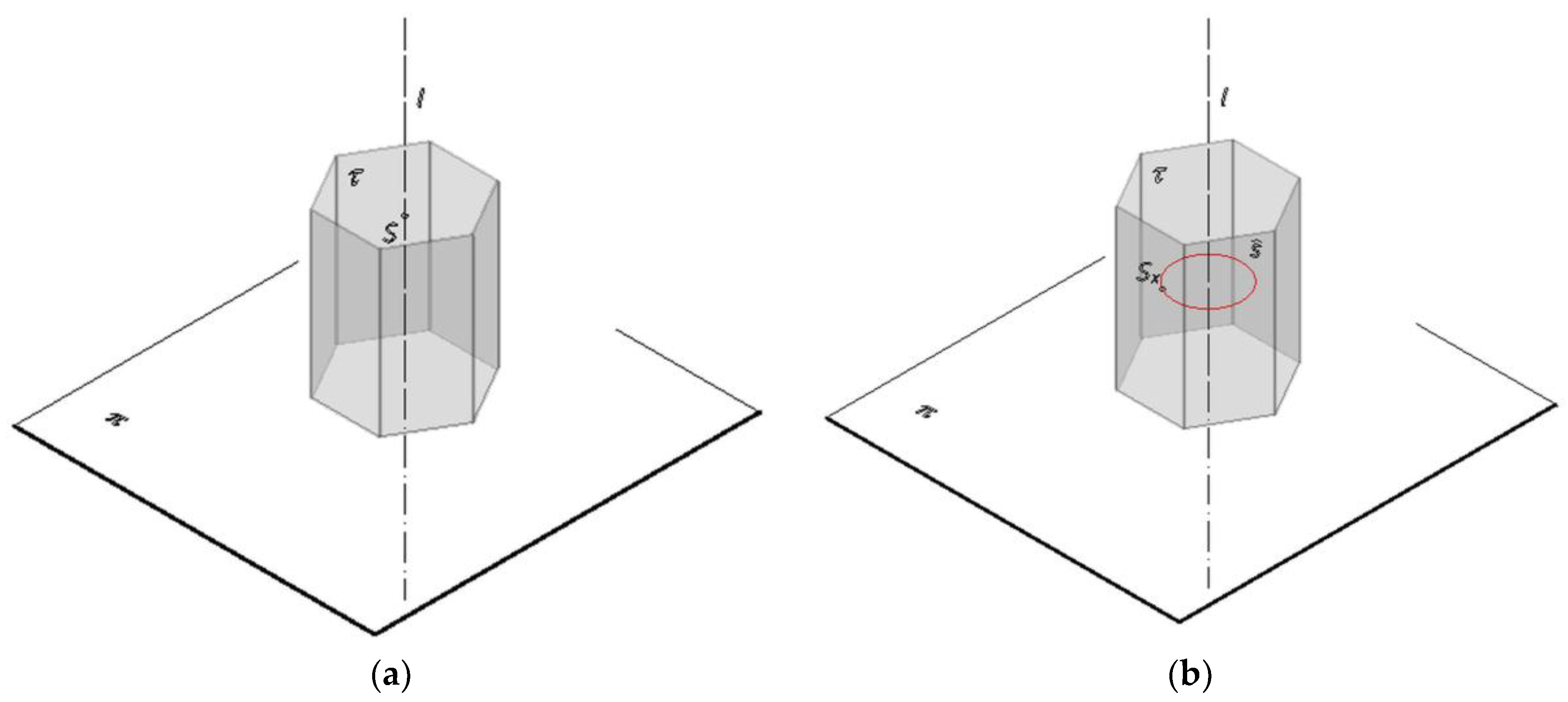
Figure 1. Projection apparatus: (a) Panorama on a prism surface from a stationary center S; and (b) panorama on a prism surface from a moving center SX.
Symmetry 09 00214 g001
Figure 2. Projection apparatus of a panorama on a pyramid surface: (a) of version A; and (b) of version B.
Symmetry 09 00214 g002
Figure 3. Representation of a point F on a pyramid surface: (a) of version A from a stationary center S; and (b) of version B from a moving center SX.
Symmetry 09 00214 g003
Figure 4. Central projection StF of a generatrix line tF onto π in order to realize the transformation: (a) projection from a moving point SF in the case of a panorama on a polygonal surface; and (b) projection from a stationary point S in the case of a panorama on a pyramid surface.
Symmetry 09 00214 g004
Figure 5. Graphical connection between the range of points on the line StF and a proper range of points on the line tFR included in the unfolded surface τR in the case of panorama on a prism surface from a moving center SF.
Symmetry 09 00214 g005
Figure 6. Graphical connection between the range of points on the line StF and a proper range of points on the line tFR included in the unfolded surface τR in the case of single center panorama on a pyramid surface of version A.
Symmetry 09 00214 g006
Figure 7. Graphical connection between the range of points on the line StF and a proper range of points on the line tFR included in the unfolded surface τR in the case of a multicenter panorama on a pyramid surface of version B.
Symmetry 09 00214 g007
Figure 8. The scheme for establishing geometric and analytical relations occurring for each regular polygon.
Symmetry 09 00214 g008
Figure 9. Mapping of a single center panorama onto a regular six wall prism surface inscribed in a cylindrical surface with the radius of the base circle of 20 m from various viewer locations: (a) the horizon height equals 6 m; and (b) the horizon height equals 15 m.
Symmetry 09 00214 g009
Figure 10. Mapping a multicenter panorama onto a regular six-wall prism surface inscribed in a cylindrical surface with the radius of the base circle of 20 m and with a horizon height of 6 m.
Symmetry 09 00214 g010
Figure 11. Mapping of a single center panorama on a pyramid surface inscribed in a cylindrical surface with the radius of the base circle of 20 m from various viewer locations: (a) panorama of version A with a horizon height of 6 m—a frog’s eye view image; and (b) panorama of version B with a horizon height of 15 m—a bird’s eye view image.
Symmetry 09 00214 g011
Figure 12. Panoramic projection of several buildings onto a regular four-wall prism surface with horizon height of 7 m: (a) the location of buildings towards a projection surface; and (b) the result of the generation of the panoramic image in Mathcad.
Symmetry 09 00214 g012
Figure 13. Establishing starting assumptions (projections of edges AB and AC and a shadow line AT) for drawing a single center panoramic image on a prism surface with a horizon height of 7 m.
Symmetry 09 00214 g013
Figure 14. Mapping of a panoramic image of several buildings onto a regular four-wall prism surface with horizon height of 7 m in the AutoCAD.
Symmetry 09 00214 g014