Article

Coupling Effects of Dynamic Loads and Friction on the Gear Systems of Radial 3D Braiding Machines
College of Mechanical Engineering, Jiangsu University of Technology, Changzhou 213001, China
*
Author to whom correspondence should be addressed.
Symmetry 2026, 18(7), 1234; https://doi.org/10.3390/sym18071234
Submission received: 9 June 2026 / Revised: 4 July 2026 / Accepted: 8 July 2026 / Published: 21 July 2026
(This article belongs to the Section F: Engineering and Materials)

Abstract

During the radial braiding process, spindle motion induces periodic load excitations as they move with the turntable. Based on the kinematics analysis of the spindles, this study derives a tension-load torque mapping model and establishes a multi-degree-of-freedom (MDOF) nonlinear dynamic model that incorporates dynamic torque and gear tooth friction. The system’s governing differential equations are solved numerically using the fourth-order Runge–Kutta method to obtain steady-state responses under various combinations of tension and rotational speed. Results indicate that increasing yarn tension reduces the stability margin of the system’s phase trajectories, and the basin of attraction area for periodic motion decreases approximately linearly as the tension increases. Furthermore, friction exhibits dual characteristics across different frequency regimes: at operating frequencies below 1.05, friction acts as a damping mechanism to maintain system stability; however, beyond this threshold, the friction reversal mechanism triggers chaotic behavior.

1. Introduction

Composite materials achieve exceptional properties that are unattainable by monolithic materials through the combination of multiple constituent phases and sophisticated process design, thereby meeting the growing demand for high-performance materials in modern industry. Within this context, three-dimensional (3D) braiding technology has emerged as a prominent manufacturing approach due to its capability for continuous production. The resulting composites exhibit superior damage tolerance [1,2], remarkable impact resistance, and excellent fatigue life, which has led to their widespread application across various sectors, including aerospace, medical engineering, automotive, and marine industries [3,4].
Currently, the prohibitive cost of high-performance composites, such as 3D carbon fiber braided materials, serves as the primary barrier to their large-scale application. Consequently, enhancing production line reliability and minimizing material waste have become urgent priorities for the industry. The critical bottleneck lies in the confined design space of existing circular braiding machines, where the high-frequency oscillation and mutual friction of numerous yarns lead to severe mechanical damage or even large-scale fiber breakage during the braiding process, subsequently triggering frequent yarn rupture and fiber fly [5,6]. Currently, research primarily focuses on the optimization of braiding processes and the interactions between yarns [7,8,9,10]; however, studies addressing fiber loss induced by gear-driven vibrations in braiding machines remain significantly limited.
Current research on gear systems primarily encompasses the dynamic characteristics of single gear pairs and multi-stage gear transmissions. Early studies were predominantly focused on the dynamics of single gear pairs [11,12,13]. However, with technological advancements, gear systems have evolved in complexity, characterized by an increasing number of gear stages. Consequently, multi-stage gear systems have become a research focal point in the field of mechanical transmission. Bu [14] investigated shield tunneling machines and developed a theoretical model for mesh forces in multi-gear transmission systems considering friction, based on the lumped parameter method, and proposed a method for analyzing tooth wear failure. Hu [15] focused on ‘dual-split transmission systems’ and established a dynamic model incorporating meshing phase excitation and gyroscopic effects using the lumped parameter method, clarifying the influence of installation angles and phase relationships on load distribution. Fang [16] analyzed a steering gear system consisting of multi-stage gears and a lead screw-nut mechanism, establishing translational-rotational dynamic equations that include backlash and internal excitation errors; their study utilized the harmonic balance method to quantitatively analyze the impact of clearance size and location on the system’s dynamic response. Hua [17] developed a time-varying stiffness calculation model that accounts for gear root cracks and friction effects, demonstrating the influence of cracks on friction force distribution. Xu and Du [18,19] focused on planetary gear transmission systems, constructed non-linear dynamic models considering time-varying stiffness, comprehensive errors, and friction torque. Their results indicated that friction induces additional frequency components, leading to alterations in the system’s motion trajectories across different frequency bands.
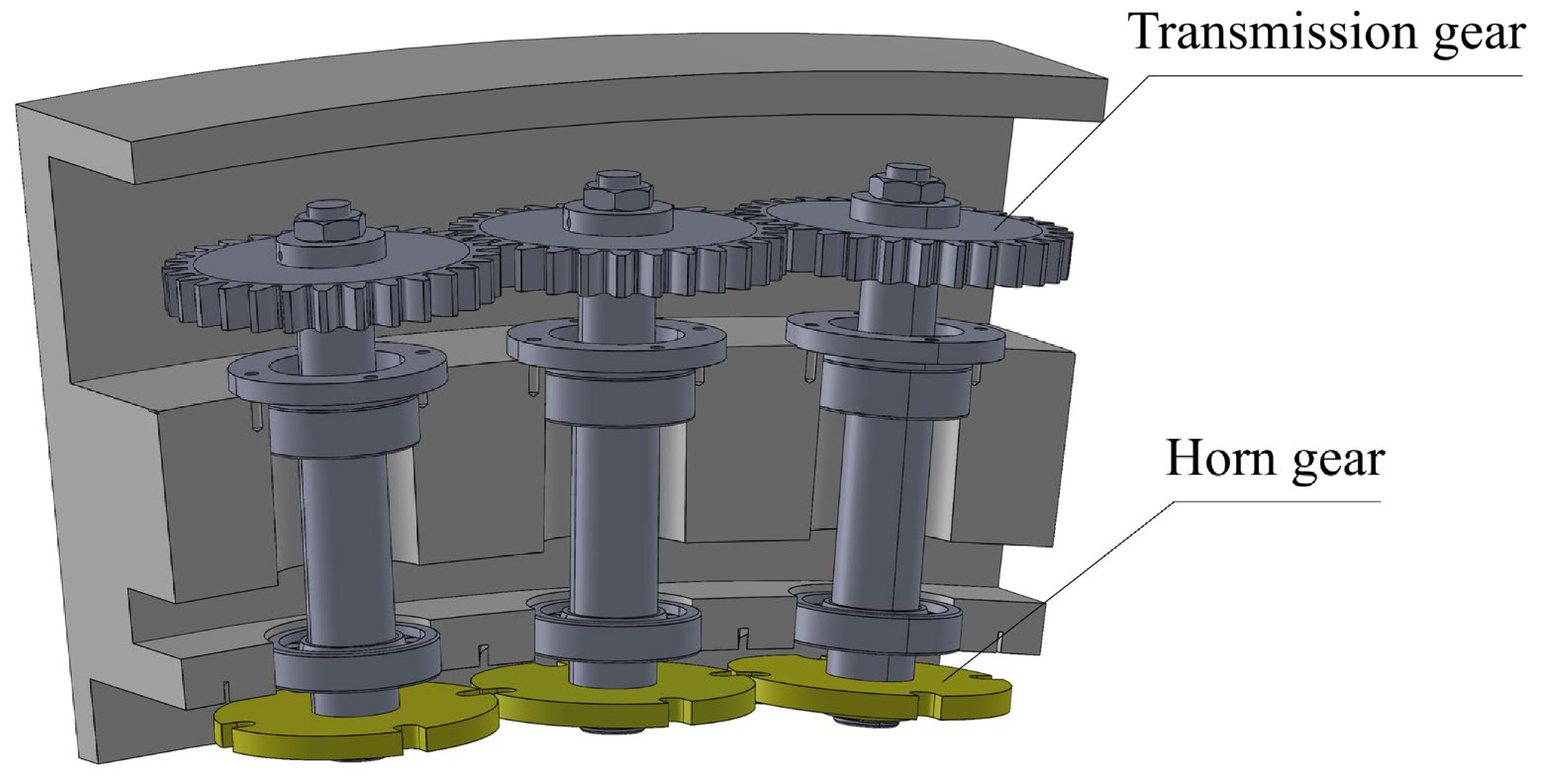
Figure 1 illustrates the internal transmission mechanism of the braiding machine, which operates as a multi-input multi-output (MIMO) system characterized by power-splitting features analogous to those of planetary gear trains, where the motor transmits power uniformly in two directions through a distribution gear to drive the entire machine. Regarding current research on braiding machine gear systems, Zhang [20] established a six-degree-of-freedom (6-DOF) nonlinear model considering random disturbances and gear eccentricity to analyze the effects of random perturbations on the system. Subsequently, Yao [21,22] extended this work by incorporating gear contact temperature and time-varying friction into a 6-DOF nonlinear model to further investigate the influence of nonlinear factors. Although these studies have addressed the dynamic effects of various factors on gear pairs, they lack a comprehensive model of the entire system. To address this, Yao and Liu [23,24] developed an N-degree-of-freedom closed-loop gear transmission system model considering dynamic displacement errors; however, their model still typically simplifies the load as a constant torque, which deviates significantly from actual braiding process conditions. Further investigation reveals that the incorporation of yarn tension introduces additional frequency components, leading to significant deviations in the accuracy of the dynamic model. Neglecting this factor may result in overly optimistic assessments of system stability under specific parameters, thereby masking potential risks. To overcome the limitations, this study utilizes spatial analytical geometry to derive a mapping relationship between yarn tension and the equivalent gear transmission torque. By integrating this relationship, a multi-degree-of-freedom (MDOF) dynamic model is established, effectively incorporating both yarn tension fluctuations and gear friction. The resulting dimensionless equations are solved using the Runge–Kutta method, providing a robust theoretical basis for system parameter optimization and stability control.
The remainder of this paper is organized as follows: Section 2 details the dynamic modeling of the radial 3D braiding machine. Section 3 identifies the sources of dynamic influence parameters and establishes the system’s equations of motion. Section 4 uses MATLAB (2022) to simulate the nonlinear differential equations, analyzing and discussing the influence of different parameters on nonlinear dynamics. Section 5 presents concluding remarks.

2. Nonlinear Dynamic Model

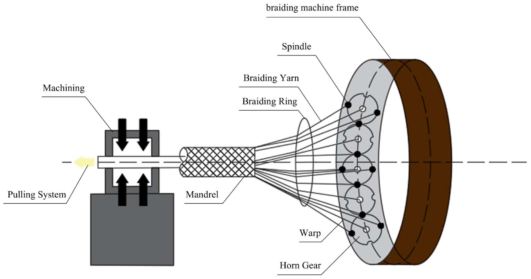
Figure 2 illustrates the working principle of the radial 3D braiding machine. It primarily comprises a braiding machine base, spindles, a horn gear, braiding rings, and a mandrel. During the braiding process, the yarn progressively interweaves and gathers at the mandrel through the braiding rings.
The braiding process is primarily driven by two coordinated actuators. First, two sets of spindles are mounted in pairs onto the horn gears located on the machine base. Upon initiation, the motor drives the gear train, inducing rotation in the horn gears; consequently, the two spindle sets move along a figure-eight trajectory in clockwise and counterclockwise directions, respectively. Second, a mandrel is positioned perpendicular to the machine base. Actuated by a traction device, the yarns are interwoven to form the fabric onto the mandrel surface. Based on this working principle, the dynamic stability of the gear system directly influences the mechanical properties of the fabric formed on the mandrel.
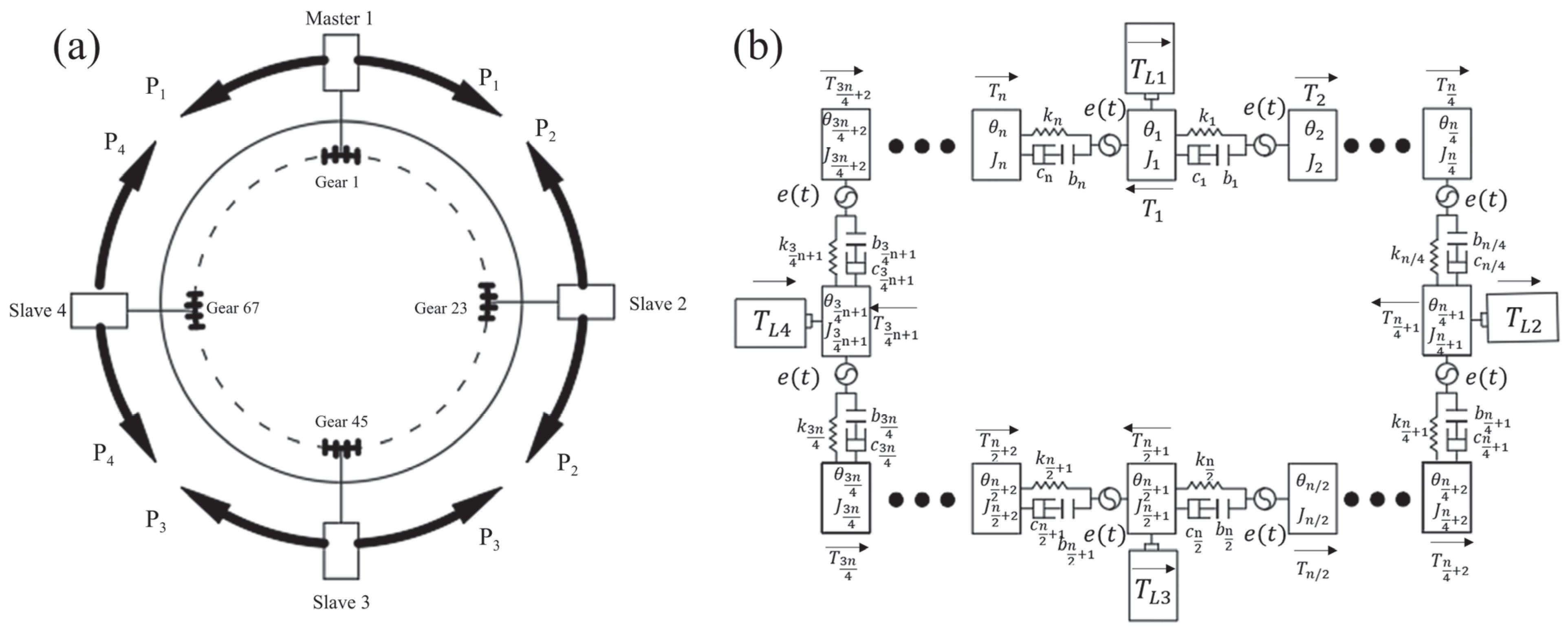
Taking the radial 3D braiding machine as the research object, Figure 3a displays the internal gear layout and power transmission diagram. The braiding machine’s gear train constitutes a closed-loop multistage gear meshing system, which exhibits power-splitting characteristics analogous to those of planetary gear systems [25]. Therefore, this transmission feature will be strictly followed during the formulation of the dynamic model. Figure 3b illustrates the corresponding gear dynamic model, where n = 88. Through structural and power distribution analysis of the model, it can be observed that the system exhibits perfect symmetry across all four quadrants. Furthermore, to ensure excellent mechanical properties of the final fabric, the transmission gears of the braiding machine are selected to be identical models. Based on this inherent symmetry, and to enhance the conciseness and readability of the manuscript, this paper presents only the governing dynamic equations for the first quadrant. The dynamic equations for the remaining quadrants can be readily obtained through cyclic mapping of the corresponding indices.
As illustrated in Figure 3b, TL1, TL2, TL3, and TL4 denote the output torques of the master and slave motors; Ti represents the output torque of the gear; θ i is the angular displacement of the gear; J i signifies the rotational inertia of the gear; e(t) is the comprehensive gear meshing error; Ki acts as the comprehensive meshing stiffness of the gear pair; Ci is the meshing damping of the gear pair; and bi denotes the backlash (where i = 1,2, …, 88).

3. System Dynamic Equations

3.1. Parameters Affecting Dynamics

3.1.1. Time-Varying Meshing Stiffness and Damping

Methods for solving the time-varying meshing stiffness of gears are primarily categorized into the potential energy method and the finite element method. However, compared with the potential energy method, the time-varying meshing stiffness derived from the finite element method is more consistent with the actual situation [26]. Therefore, this paper uses the finite element simulation method to solve the meshing stiffness of gear pairs. During the solution process, ANSYS (2024) software is used for mesh generation, preprocessing, simulation calculations, and other tasks.
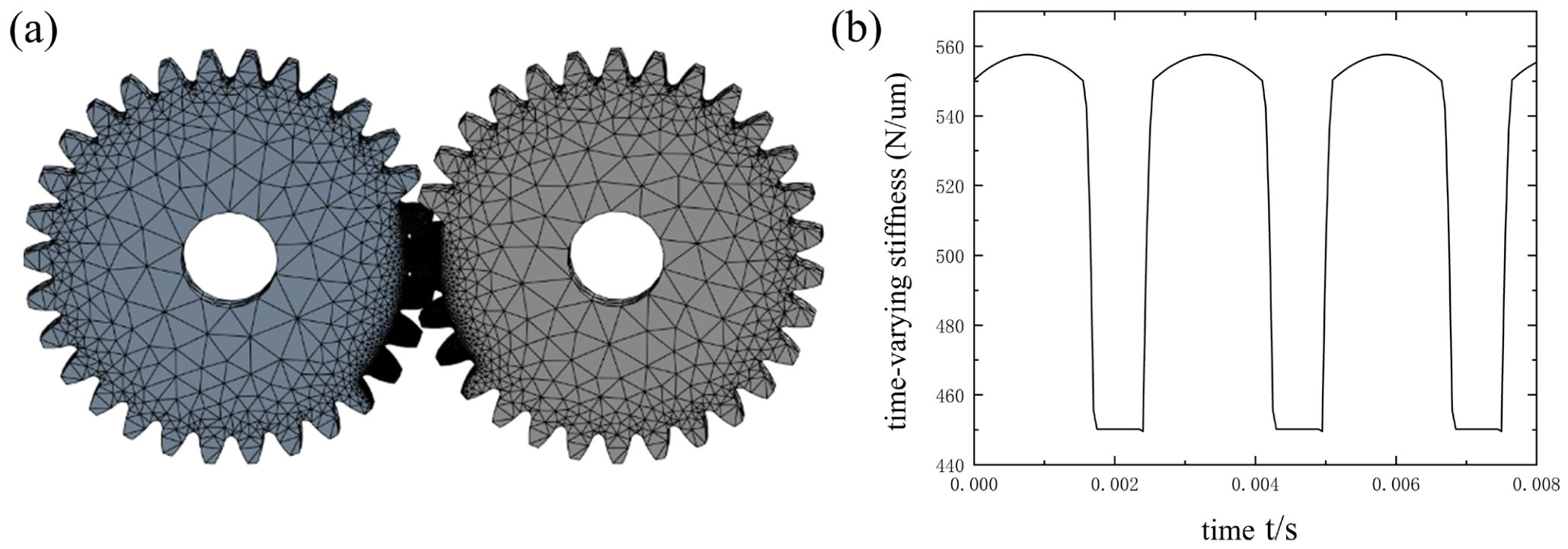
Figure 4a illustrates the tetrahedral mesh of the gear. Given that the meshing stiffness of the gear is periodic, it is sufficient to perform the meshing simulation for only a few tooth pairs to capture the stiffness characteristics of the entire gear pair. This approach effectively reduces the number of unnecessary mesh elements, thereby significantly improving computational efficiency.
Finally, based on numerical simulations performed in ANSYS, the angular displacements of the driving and driven gears were obtained over time. From these results, the transmission error and time-varying meshing stiffness were derived. As shown in Figure 4b, the meshing stiffness of the braiding machine gear pair exhibits a periodic profile, with a maximum value of 5.57 × 10 8 N / M and a minimum value of 4.50 × 10 8 N / M .
The mesh stiffness of a gear pair is typically modeled as a periodic rectangular wave that varies with the meshing frequency [27]. According to the Fourier series expansion of this rectangular wave, the stiffness fluctuations are dominated by the fundamental gear mesh frequency, while the amplitudes of higher-order harmonics decrease rapidly as the order increases. Therefore, it is common practice to simplify the model by considering only the fundamental component, as expressed in the following equation:
k h ( t ) = k 0 + k v cos ω h t + δ ω h
where k 0 is the average meshing stiffness of the gear pair; k v is the variation amplitude of meshing stiffness; ω h denotes the meshing stiffness of the gear pair; δ ω h is the initial phase angle of the gear.
The gear mesh damping can be calculated by the following equation:
c m = 2 ξ g k h R p 2 R g 2 I p I g R p 2 I p + R g 2 I g
ξ g denotes the damping ratio of the gear mesh, which typically ranges from 0.03 to 0.17.

3.1.2. Tooth Backlash

To prevent interference and potential seizure during gear meshing, a specific clearance is typically maintained between the non-working tooth surfaces. However, manufacturing inaccuracies, installation errors, and operational wear can lead to excessive backlash, which subsequently triggers abnormal vibration and noise within the gear transmission system. To account for this nonlinear phenomenon in the dynamic model, the following piecewise nonlinear function, as shown in Equation (3), is introduced to represent the backlash effect:
f X = X b , X > b 0 , b X b X + b , X < b
b represents the half-backlash, which is defined as a fixed parameter in this study ( b = 2.65 × 10 4 m m ) [23].

3.1.3. Transmission System Excitation

The excitation sources in a gear transmission system are primarily categorized into two types: external and internal. For standard gear pairs, low-frequency excitation, arising from fluctuations in load torque, is typically classified as external excitation. Conversely, high-frequency excitation, resulting from installation errors, gear tooth elastic deformation, and other factors, is treated as internal excitation.
The harmonic function of internal excitation is as follows:
e ( t ) = e sin ( ω eh t + ϕ a )
where ω e h is the fundamental frequency of internal excitation; e is the static transmission error amplitude; based on the gear elastic deformation characteristics derived from ANSYS finite element simulations, this study sets the transmission error amplitude to 10   μ m ; ϕ a is the initial phase angle.
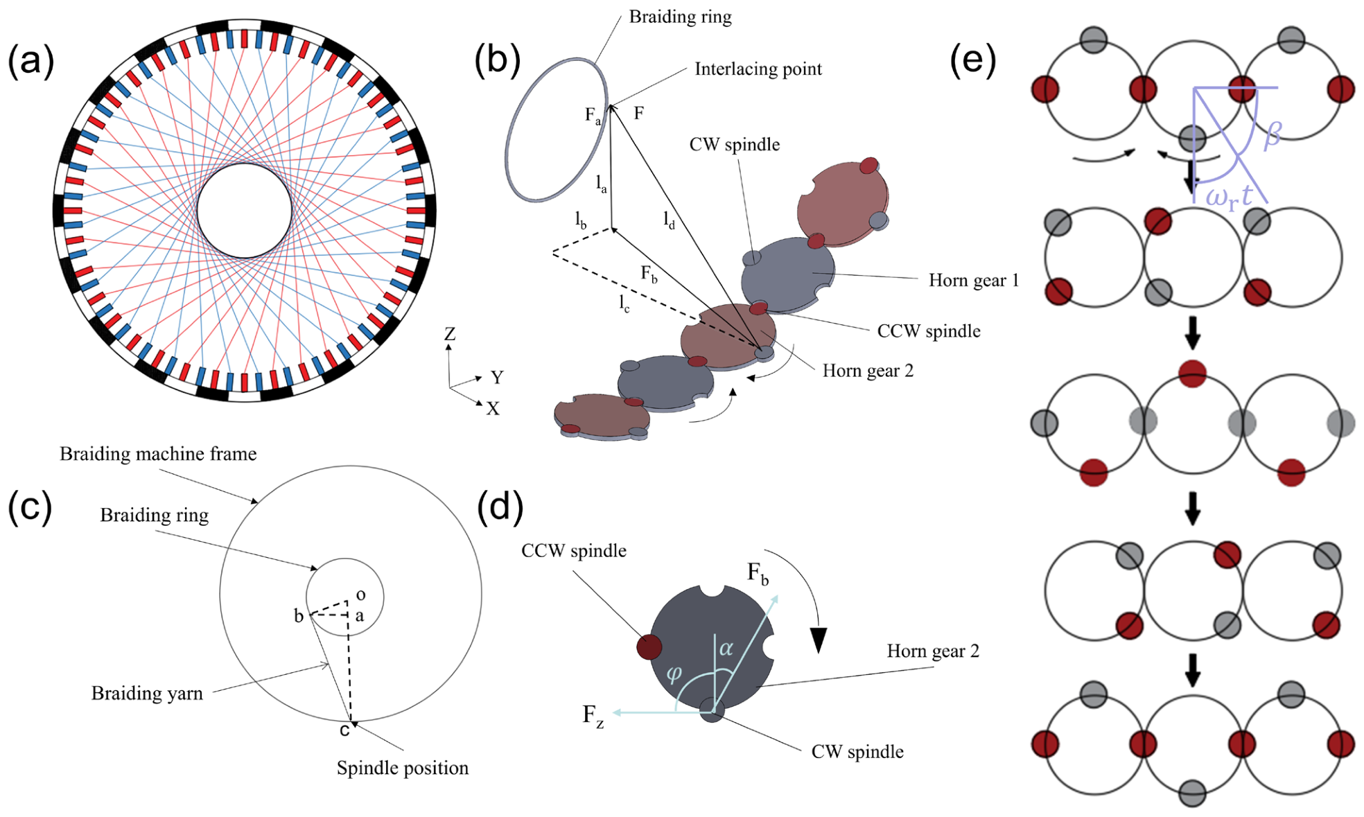
During the braiding process, the spindles continuously move, reciprocating motion on the horn gears, as illustrated in Figure 5a, which is a schematic diagram of braiding; Figure 5b is a force analysis diagram of the yarn, where F is the dynamic tension of the yarn, Fa is the component of the tension F projected on the Z-axis and the axial force generated on the spindle, and Fb is the component of the tension F projected on the XY plane and the resistance caused to the movement of the spindle. l a , l b , l c represent the projected distances of the yarn in the Z, Y, and X directions, respectively. Figure 5c is a simplified diagram of a single spindle braiding. Regardless of the spindle’s position, the yarn is always the braiding ring. Point o is the center of the braiding loop; point c is the position of the spindle; point b is the position where the yarn acts on the braiding loop; point a is the foot of the perpendicular from point b to line segment oc. Finally, Figure 5d and Figure 5e provide the force analysis and the motion trajectory of the spindle, respectively.
l b c = l o c 2 l o b 2
l a b = l o b l b c l o c = l o b l o c l o c 2 l o b 2
l a c = l b c 2 l a b 2 = ( l o c 2 l o b 2 ) 2 ( l o b l o c l o c 2 l o b 2 ) 2
l d = ( ( l c 2 + l b 2 ) 2 + l a 2 )
where segment l o b is the braiding ring radius; l o c is the rotation radius of the spindle; l a c and l a b in Figure 5c correspond to l a and l b in Figure 5b. During the braiding process, the corresponding line segments l a and l b for both clockwise (CW) and counterclockwise (CCW) spindles remain constant. The length of segment l c is calculated as shown in Equation (8):
C W   s p i n d l e s   o n   Horn   G e a r   2 : l c 1 = l z + Rsin   ( mod ( ω r t + β ,   π ) ) C C W   s p i n d l e s   o n   Horn   G e a r   2 : l c 2 = l z Rsin   ( mod ( ω r t + β + π 2 ,   π ) ) C W   s p i n d l e s   o n   Horn   G e a r   1 : l c 1 = l z Rsin   ( mod ( ω r t + β ,   π ) ) C C W   s p i n d l e s   o n   Horn   G e a r   1 : l c 2 = l z + Rsin   ( mod ( ω r t + β + π 2 ,   π ) )
F b = F l c 2 + l b 2 l d = F l c 2 + l b 2 ( ( l c 2 + l b 2 ) 2 + l a 2 )
F a = F l a l d = F l a ( ( l c 2 + l b 2 ) 2 + l a 2 )
where l z is the distance from the center of the horn gear to the braiding ring along the X-axis; R is the radius of the horn gear; ω r t is the rotation angle of the horn gear ( ω r = ω h z ); mod denotes the modulo function; β is the initial angle of the horn gear; F b represents the resistive load imposed on the gear by the yarn tension; F a represents the axial component of the yarn tension acting on the gear.
α = tan   ( l b l c )
C W   s p i n d l e s   o n   Horn   G e a r   2 : φ 1 = π mod ( ω r t + β ,   π ) C C W   s p i n d l e s   o n   Horn   G e a r   2 : φ 2 = mod   ( π 2 + mod ( ω r t + β ,   π ) ,   π ) C W   s p i n d l e s   o n   Horn   G e a r   1 : φ 1 = mod ( ω r t + β ,   π ) C C W   s p i n d l e s   o n   Horn   G e a r   1 : φ 2 = π mod   ( π 2 + mod   ( ω r t + β ,   π ) ,   π )
F z = F b cos ( α + φ )
Therefore, the rotation torque of the horn gear T is given by: T = T 0 + F z 1 · R + F z 2 · R , where α is the angle between the force F b and the X-axis; φ is the angle between the force F Z and the X-axis; T 0 is the intrinsic torque of the gear system driving the horn gear and other components. F z 1 · R + F z 2 · R represents the influence of the yarn tension on the gear torque.
The operating tension of the braiding machine typically ranges from 0–6 N. Experimental measurements indicate that under steady-state operating conditions, the fluctuations in yarn tension remain within ± 4 % of the nominal value [28]. We conducted a sensitivity analysis of the turntable torque within this fluctuation range. The results demonstrate that the maximum relative variation in turntable torque induced by yarn tension fluctuations is less than 3 % , and the overall trend and phase characteristics of the torque variation remain highly consistent. Based on this quantitative analysis, this study treats yarn tension as a prescribed force to prevent computational divergence caused by high-frequency tension fluctuations, thereby ensuring the stability and validity of the dynamic model.

3.2. Calculation of Friction Force and Friction Arm

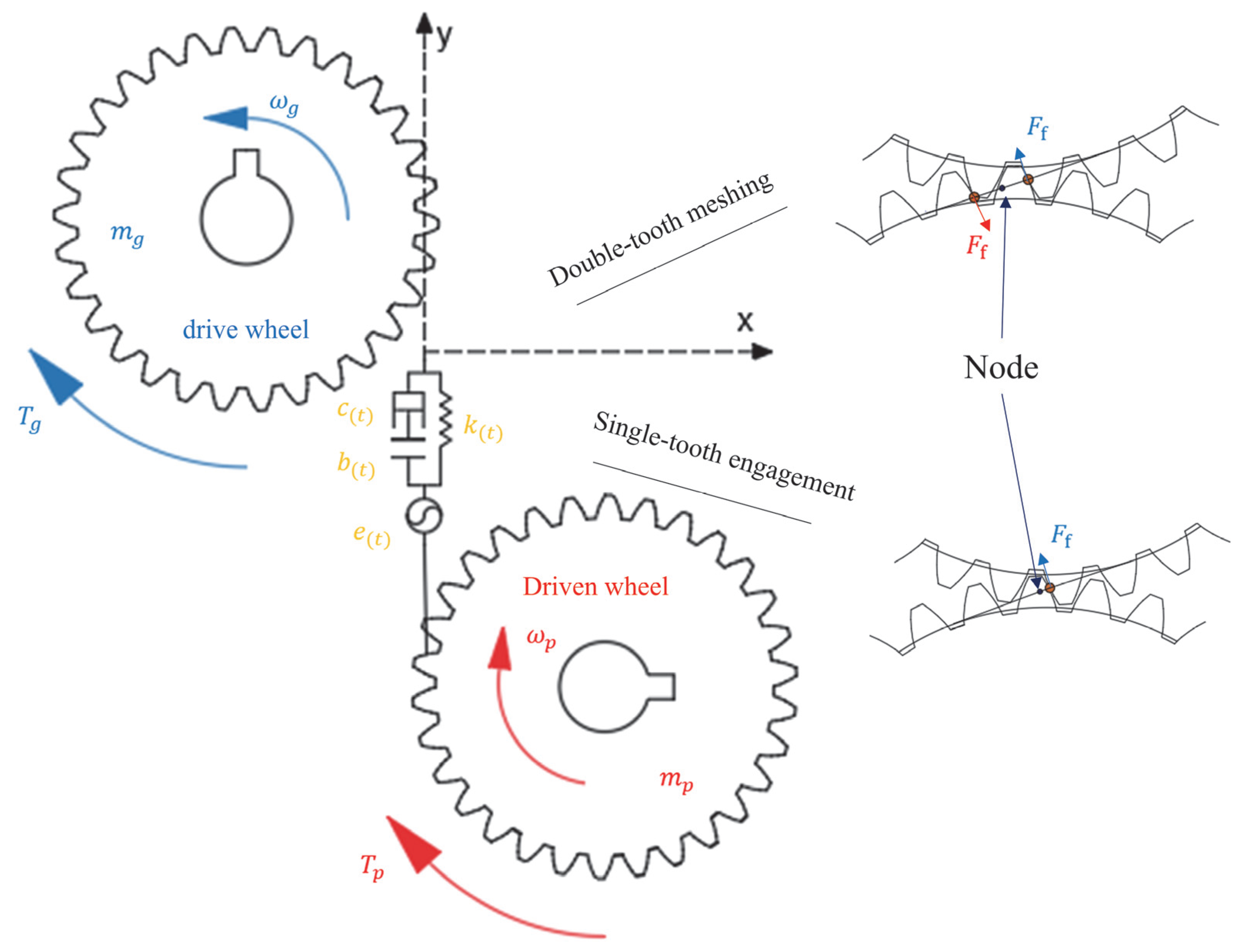
During the gear meshing process, mutual contact and relative sliding between the tooth surfaces generate tangential resistance. According to Coulomb’s friction law, let f be the tooth surface friction force and λ be the directional coefficient; the friction force can then be expressed as:
f = λ μ F λ = sgn [ L P r b p tan α ]
where μ is the friction coefficient of the tooth surface, and sgn is the signum function. It is defined as follows: sgn(x) equals 1 when x is greater than 0, 0 when x equals 0, and −1 when x is less than 0. L P is the time-varying friction moment arm, r b p is the base circle radius of the gear, and α is the pressure angle.
Since the contact ratio of gear transmission is greater than 1, two distinct meshing conditions occur within a single meshing cycle, as illustrated in Figure 6. Therefore, the calculation formula for the friction moment arm is as follows [19].
Friction moment arm of the first meshing tooth pair:
L 11 = r a 1 2 r b 1 2 ( ε 1 ) S p b + mod ( ω r r b 1 t + l p , S p b ) , 0 < mod ( ω r r b 1 t + l p , S p b ) < ( ε 1 ) S p b 0 , ( ε 1 ) S p b < mod ( ω r r b 1 t + l p , S p b ) < S p b
L 21 = r a 2 2 r b 2 2 S p b mod ( ω r r b 1 t + l p , S p b ) , 0 < mod ( ω r r b 1 t + l p , S p b ) < ( ε 1 ) S p b 0 , ( ε 1 ) S p b < mod ( ω r r b 1 t + l p , S p b ) < S p b
Friction moment arm of the second meshing tooth pair:
L 12 = r a 1 2 r b 1 2 ε S p b + mod ( ω r r b 1 t + l p , S p b ) L 22 = r a 2 2 r b 2 2 mod ( ω r r b 1 t + l p , S p b )
where ε is the contact ratio, By substituting the parameters listed in Table 1 into the theoretical governing equations: ε = r a 1 2 r b 1 2 + r a 2 2 r b 2 2 a sin α π m cos α , taken as 1.65 in this study; S p b is the gear pitch; L 11 and L 12 are the friction moment arms of the first and second tooth pairs relative to gear 1, respectively; L 21 and L 22 are the friction moment arms of the first and second tooth pairs relative to gear 2, respectively; ω r represents the rotational angular frequency of the gear; l p is the initial value of the friction moment arm; “mod” denotes the modulo function; r a denotes the tip circle radius; r b represents the base circle radius.

3.3. Dynamic Modeling of Multi-Gear Transmission Systems

Figure 3 illustrates the corresponding gear dynamic model of the braiding machine. Leveraging the inherent symmetry specific to the braiding machine’s gear train, this paper specifically details the governing dynamic equations of the multi-gear transmission system for the first quadrant, as formulated in Equation (18). The governing equations for the remaining quadrants can be readily derived through cyclic index mapping.
J 1 θ ¨ 1 + R b 1 F d 1 - 2 + R b 1 F d 1 - n = T L 1 T 1 J 2 θ ¨ 2 R b 2 F d 1 - 2 + R b 2 F d 2 - 3 = T 2 J n 8 θ ¨ n 8 R b ( n 8 ) F d ( n 8 1 ) - ( n 8 ) + R b ( n 8 ) F d ( n 8 ) - ( n 8 + 1 ) = T n 8 J ( n 8 + 1 ) θ ¨ ( n 8 + 1 ) R b ( n 8 + 1 ) F d ( n 8 ) - ( n 8 + 1 ) R b ( n 8 + 1 ) F d ( n 8 + 2 ) - ( n 8 + 1 ) = T ( n 8 + 1 ) J ( n 8 + 2 ) θ ¨ ( n 8 + 2 ) R b ( n 8 + 2 ) F d ( n 8 + 3 ) - ( n 8 + 2 ) + R b ( n 8 + 2 ) F d ( n 8 + 2 ) - ( n 8 + 1 ) = T ( n 8 + 2 ) J n 4 θ ¨ n 4 R b n 4 F d ( n 4 + 1 ) - ( n 4 ) + R b ( n 4 ) F d ( n 4 ) - ( n 4 1 ) = T n 4 J ( n 4 + 1 ) θ ¨ ( n 4 + 1 ) + R b ( n 4 + 1 ) F d ( n 4 + 1 ) - ( n 4 ) + R b ( n 4 + 1 ) F d ( n 4 + 1 ) - ( n 4 + 2 ) = T L 2 T ( n 4 + 1 )
where the transmission error x between moving bodies and the dynamic meshing force F are calculated as shown in Equations (20) and (21). By replacing the torsional torques R b j F d j i and R b i F d j i in these equations with R b j F d j i + f d 1   j i L 11 + f d 2   j i L 12 and R b i F d j i + f d 1   j i L 21 + f d 2   j i L 22 , the dynamic influence of friction on the gear system can be analyzed [19]. Here, f d 1 = F d · L 1 · λ · μ ,   f d 2 = F d · L 2 · λ · μ , and L 1 and L 2 represent the load sharing ratios of the meshing gear teeth.
x 1 = R b 1 θ 1 R b 2 θ 2 e ( t ) x 2 = R b 2 θ 2 R b 3 θ 3 e ( t ) x ( n 8 ) = R b ( n 8 ) θ ( n 8 ) R b ( n 8 + 1 ) θ ( n 8 + 1 ) e ( t ) x ( n 8 + 1 ) = R b ( n 8 + 2 ) θ ( n 8 + 2 ) R b ( n 8 + 1 ) θ ( n 8 + 1 ) e ( t ) x ( n 4 1 ) = R b ( n 4 ) θ ( n 4 ) R b ( n 4 1 ) θ ( n 4 1 ) e ( t ) x ( n 4 ) = R b ( n 4 + 1 ) θ ( n 4 + 1 ) R b ( n 4 ) θ ( n 4 ) e ( t )
F d 1 - 2 = C 1 x ˙ 1 + K 1 f ( x 1 ) F d 2 - 3 = C 2 x ˙ 2 + K 2 f ( x 2 ) F d ( n 8 ) - ( n 8 + 1 ) = C ( n 8 ) x ˙ ( n 8 ) + K ( n 8 ) f ( x ( n 8 ) ) F d ( n 8 + 2 ) - ( n 8 + 1 ) = C ( n 8 + 1 ) x ˙ ( n 8 + 1 ) + K ( n 8 + 1 ) f ( x ( n 8 + 1 ) ) F d ( n 4 ) - ( n 4 1 ) = C ( n 4 1 ) x ˙ ( n 4 1 ) + K ( n 4 1 ) f ( x ( n 4 1 ) ) F d ( n 4 + 1 ) - ( n 4 ) = C ( n 4 ) x ˙ ( n 4 ) + K ( n 4 ) f ( x ( n 4 ) )
By introducing dimensionless variables for time and length, such as τ = ω n t and x n ¯ = x n / b 0 , where ω n and b 0 are the reference values for frequency and backlash, respectively, substituting Equations (20) and (21) into Equation (19) and performing the non-dimensionalization process yield the following equations:
x ¯ ¨ 1 = R b 1 ( T L 1 T 1 ) J 1 + R b 2 T 2 J 2 ( 1 + g 1 ( τ ) ) R b 1 2 J 1 + R b 2 2 J 2 [ C 1 x ¯ ˙ 1 + K 1 f ( x ¯ 1 ) ] ( 1 + g 2 ( τ ) ) R b 1 2 J 1 [ C n x ¯ ˙ n + K n f ( x ¯ n ) ] + ( 1 + g 2 ( τ ) ) R b 2 2 J 2 [ C 2 x ¯ ˙ 2 + K 2 f ( x ¯ 2 ) ] e ¯ ¨ ( τ ) x ¯ ¨ 2 = R b 2 T 2 J 2 + R b 3 T 3 J 3 ( 1 + g 1 ( τ ) ) R b 2 2 J 2 + R b 3 2 J 3 [ C 2 x ¯ ˙ 2 + K 2 f ( x ¯ 2 ) ] + ( 1 + g 3 ( τ ) ) R b 2 2 J 2 [ C 1 x ¯ ˙ 1 + K 1 f ( x ¯ 1 ) ] + ( 1 + g 2 ( τ ) ) R b 3 2 J 3 [ C 3 x ¯ ˙ 3 + K 3 f ( x ¯ 3 ) ] e ¯ ¨ ( τ ) x ¯ ¨ ( n 8 ) = R b ( n 8 ) T ( n 8 ) J ( n 8 ) + R b ( n 8 + 1 ) T ( n 8 + 1 ) J ( n 8 + 1 ) ( 1 + g 1 ( τ ) ) R b ( n 8 ) 2 J ( n 8 ) + R b ( n 8 + 1 ) 2 J ( n 8 + 1 ) [ C ( n 8 ) x ¯ ˙ ( n 8 ) + K ( n 8 ) f ( x ¯ ( n 8 ) ) ] + ( 1 + g 3 ( τ ) ) R b ( n 8 ) 2 J ( n 8 ) [ C ( n 8 1 ) x ¯ ˙ ( n 8 1 ) + K ( n 8 1 ) f ( x ¯ ( n 8 1 ) ) ] ( 1 + g 3 ( τ ) ) R b ( n 8 + 1 ) 2 J ( n 8 + 1 ) [ C ( n 8 + 1 ) x ¯ ˙ ( n 8 + 1 ) + K ( n 8 + 1 ) f ( x ¯ ( n 8 + 1 ) ) ] e ¯ ¨ ( τ ) x ¯ ¨ ( n 8 + 1 ) = R b ( n 8 + 2 ) T ( n 8 + 2 ) J ( n 8 + 2 ) + R b ( n 8 + 1 ) T ( n 8 + 1 ) J ( n 8 + 1 ) ( 1 + g 1 ( τ ) ) R b ( n 8 + 2 ) 2 J ( n 8 + 2 ) + R b ( n 8 + 1 ) 2 J ( n 8 + 1 ) [ C ( n 8 + 1 ) x ¯ ˙ ( n 8 + 1 ) + K ( n 8 + 1 ) f ( x ¯ ( n 8 + 1 ) ) ] + ( 1 + g 3 ( τ ) ) R b ( n 8 + 2 ) 2 J ( n 8 + 2 ) [ C ( n 8 + 2 ) x ¯ ˙ ( n 8 + 2 ) + K ( n 8 + 2 ) f ( x ¯ ( n 8 + 2 ) ) ] ( 1 + g 3 ( τ ) ) R b ( n 8 + 1 ) 2 J ( n 8 + 1 ) C ( n 8 ) x ¯ ˙ ( n 8 ) + K ( n 8 ) f ( x ¯ ( n 8 ) ) e ¯ ¨ ( τ ) x ¯ ¨ ( n 4 1 ) = R b ( n 4 ) T ( n 4 ) J ( n 4 ) + R b ( n 4 1 ) T ( n 4 1 ) J ( n 4 1 ) ( 1 + g 1 ( τ ) ) R b ( n 4 ) 2 J ( n 4 ) + R b ( n 4 1 ) 2 J ( n 4 1 ) [ C ( n 4 1 ) x ¯ ˙ ( n 4 1 ) + K ( n 4 1 ) f ( x ¯ ( n 4 1 ) ) ] + ( 1 + g 3 ( τ ) ) R b ( n 4 ) 2 J ( n 4 ) [ C ( n 4 ) x ¯ ˙ ( n 4 ) + K ( n 4 ) f ( x ¯ ( n 4 ) ) ] + ( 1 + g 2 ( τ ) ) R b ( n 4 1 ) 2 J ( n 4 1 ) [ C ( n 4 2 ) x ¯ ˙ ( n 4 2 ) + K ( n 4 2 ) f ( x ¯ ( n 4 2 ) ) ] e ¯ ¨ ( τ ) x ¯ ¨ ( n 4 ) = R b ( n 4 + 1 ) ( T L 2 T ( n 4 + 1 ) ) J ( n 4 + 1 ) + R b ( n 4 ) T ( n 4 ) J ( n 4 ) ( 1 + g 1 ( τ ) ) R b ( n 4 ) 2 J ( n 4 ) + R b ( n 4 + 1 ) 2 J ( n 4 + 1 ) [ C ( n 4 ) x ¯ ˙ ( n 4 ) + K ( n 4 ) f ( x ¯ ( n 4 ) ) ] ( 1 + g 2 ( τ ) ) R b ( n 4 + 1 ) 2 J ( n 4 + 1 ) [ C ( n 4 + 1 ) x ¯ ˙ ( n 4 + 1 ) + K ( n 4 + 1 ) f ( x ¯ ( n 4 + 1 ) ) ] + ( 1 + g 2 ( τ ) ) R b ( n 4 ) 2 J ( n 4 ) [ C ( n 4 1 ) x ¯ ˙ ( n 4 1 ) + K ( n 4 1 ) f ( x ¯ ( n 4 1 ) ) ] e ¯ ¨ ( τ )
Since the parameters of all gears in the braiding machine are identical, the base circle radii of the gears are uniformly represented by R b p . The relationship between the dimensionless friction coefficients is formulated as follows:
g 1 τ = λ μ L 1 ( L 11 + L 21 ) 2 R b p + λ μ L 2 ( L 12 + L 22 ) 2 R b p , g 2 τ = λ μ L 1 L 11 R b p + λ μ L 2 L 12 R b p , g 3 τ = λ μ L 1 L 21 R b p + λ μ L 2 L 22 R b p   .

4. Results and Discussion

Kahraman [29] experimentally demonstrated the existence of nonlinear mechanical behavior in such systems. Building upon previous analyses [30,31], the feasibility of the proposed modeling approach is substantiated, as it facilitates both qualitative and quantitative descriptions of system dynamics. Xu [18] investigated the dynamic impact of tooth surface friction, revealing that for planetary gear systems, friction introduces additional subharmonic components into the periodic response, promoting order in the low-frequency range while extending the chaotic regime in the high-frequency range. Accordingly, based on the work of Liu and Yao, this study conducts a radial analysis of the gear system in a radial braiding machine. We investigate whether this closed-loop gear system exhibits behavior analogous to planetary gear systems to validate the accuracy of our model. Furthermore, the influence of these key parameters on system stability is comprehensively analyzed.
This paper investigates the transmission system of a radial 3D braiding machine, which comprises 88 closed-loop gears driven by four synchronous motors. Direct numerical simulation of the full-scale system would lead to exponential growth in computational complexity, exacerbated by inherent nonlinearities and a large number of degrees of freedom (DOFs), which often compromise the numerical stability of the simulation. As previously established, the braiding machine’s gear train exhibits perfect geometric and dynamic symmetry. Consequently, focusing the dynamic analysis on the first quadrant (Gears 1 to 23) is sufficient to characterize the entire system. Furthermore, in such closed-loop gear trains, despite identical component specifications, perturbations originating from backlash and static transmission errors inevitably accumulate during power propagation. Given that peak vibration displacement typically manifests at the confluence gear [24] (Gear 12), this study primarily centers on the dynamic analysis of this specific component.
Taking the gear transmission system of the radial 3D braiding machine shown in Figure 3 as a baseline, we formulate the equations of motion for the n-element gear train, incorporating parameters such as dynamic loads and tooth surface friction. The basic parameters of the gears are listed in Table 1, where all gears within the braiding machine share identical specifications. The Runge–Kutta method is employed to numerically solve the system of governing differential equations. The dimensionless external load excitation frequency is set to ω e = ω h / ω n , the dimensionless damping ratio is ζ = 0.1 , and the stiffness ratio is k v k 0 = 0.1. By setting the initial displacements and initial velocities of the system to zero, the dynamic response characteristics of the system under varying parameters are obtained. Various diagnostic methods, including bifurcation diagrams, phase-plane portraits, and Lyapunov exponent spectra, are utilized to intuitively characterize the dynamic response signatures of the braiding machine’s gear system under different operational regimes.

4.1. Analysis of the Impact of Yarn Tension on Gear Dynamic Characteristics

The gear system is significantly influenced by frequency variations. In practical engineering operations, machines should ideally operate at higher frequencies to enhance system efficiency. However, it is essential to ensure that the meshing frequency remains far removed from the natural frequencies to mitigate system-induced vibration and noise. Therefore, investigating the impact of frequency variations across different frequency bands plays a crucial role in the optimal design and selection of gears.
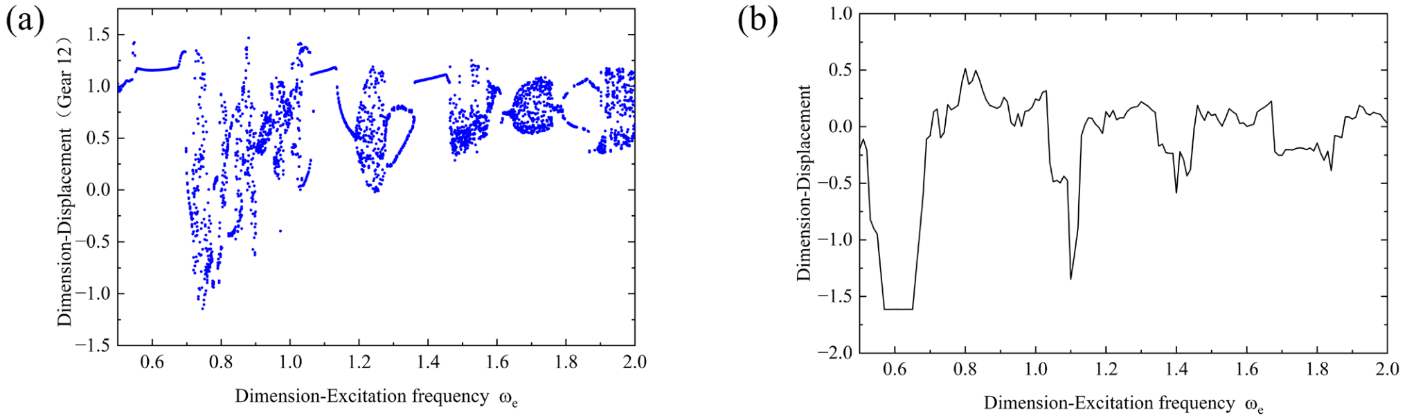
If the influence of yarn tension on the gears is neglected, the parameters are set as   F = 0   N and T 0 = 1.5   N · M . Figure 7 illustrates the corresponding dynamic characteristic diagrams of the braiding machine’s gear system. The left plot displays the bifurcation diagram of the system, which represents the location of the meshing pair displacement at the same time-instance within each excitation period across different frequencies. If the location consists of a single point or a few fixed points, the system is in periodic motion; if the displacement varies slightly from the previous period but follows a traceable pattern, the system is in quasi-periodic motion; if the locations are disordered and irregular, the system is in a chaotic state. The right plot depicts the Lyapunov exponent diagram of the system, which is used to determine whether the system is stable. A positive exponent proves that the system is unstable, while a negative exponent proves that the system is stable. In engineering applications, the gear transmission system should ideally ensure periodic or quasi-periodic motion under most excitation frequencies, thereby guaranteeing stable operation, extending system lifespan, and reducing failure rates.
When 0.5 < ω e < 0.69 , the system is in a single-period motion state, and the corresponding Lyapunov exponent is less than 0, indicating that the system is stable at this stage. When 0.69 < ω e < 1.06 , the system evolves from single-period motion to chaotic motion; meanwhile, the corresponding Lyapunov exponent transitions from negative to positive, demonstrating that the system becomes unstable. When 1.06 < ω e < 1.18 , motion first shifts from a chaotic state to a period-2 state, and then gradually evolves into a single-period motion state. The corresponding Lyapunov exponent switches from positive to negative, indicating that the system escapes chaos and enters a stable periodic orbit. When 1.18 < ω e < 1.28 , the system enters a chaotic state, and the corresponding Lyapunov exponent is greater than 0, signifying an unstable operational state. When 1.28 < ω e < 1.46 , the system undergoes another inverse period-doubling bifurcation with a corresponding Lyapunov exponent less than 0, verifying a stable operational state. When 1.46 < ω e < 1.77 , although the system exhibits quasi-periodic motion within a narrow sub-interval in this region, it rapidly re-enters chaotic motion as the frequency increases, and the corresponding Lyapunov exponent remains greater than 0. When 1.77 < ω e < 2.0 , a period-doubling bifurcation takes place. The gear motion first transitions from chaotic motion to single-period motion, then begins to transform into period-2 motion with the increase in frequency and eventually enters into a chaotic state when the frequency exceeds 1.9. The corresponding Lyapunov exponent changing from negative to positive further confirms the transition of the system from stability to chaos.
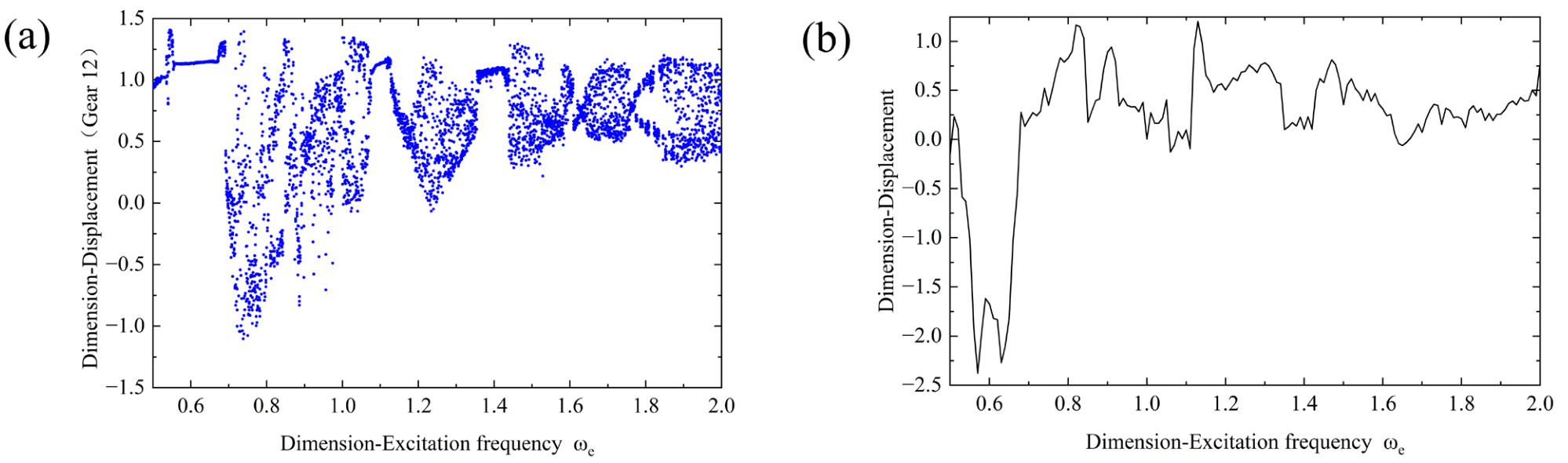
When incorporating the influence of yarn tension on the gears, the parameters are defined as F = 1   N and T 0 = 1.5   N · M . Figure 8 illustrates the corresponding dynamic response profiles of the braiding gear system. A comparative analysis between the two cases reveals that within the low-frequency regime ( 0.5 < ω e < 0.69 ), the introduction of yarn tension exerts a negligible effect on the systemic evolutionary states. This phenomenon can be attributed to the lower rotational speed, lower kinetic energy, and weaker meshing impacts at lower frequencies, which are insufficient to activate the system’s underlying nonlinear factors; consequently, the system consistently maintains a stable periodic motion state. Nevertheless, as the excitation frequency escalates beyond 1, conspicuous alterations emerge in the bifurcation diagram. Specifically, the originally orderly inverse period-doubling sequences are supplanted by fully developed chaos, and the periodic regimes are overridden by quasi-periodic attractors. This shift clearly indicates that the yarn tension accentuates the system’s nonlinearity, thereby disrupting the pristine dynamic rhythms. Mechanistically, the intervention of yarn tension breaks the baseline structural dynamics and introduces complex inter-modal nonlinear coupling. Consequently, the high-frequency input energy can no longer be confined and dissipated within a single isolated mode; instead, it propagates through the entire gearing network via internal resonance pathways, ultimately inducing dynamic instability and precipitating a plunge into chaos.
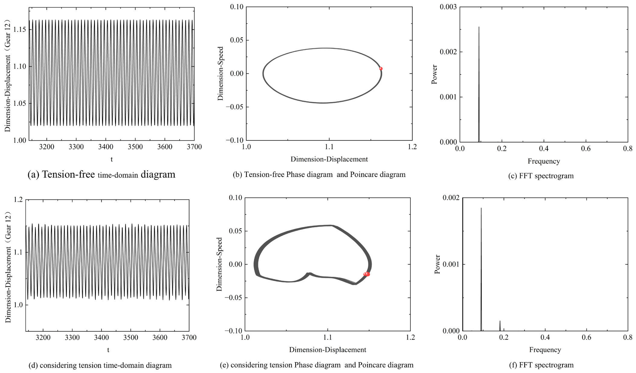
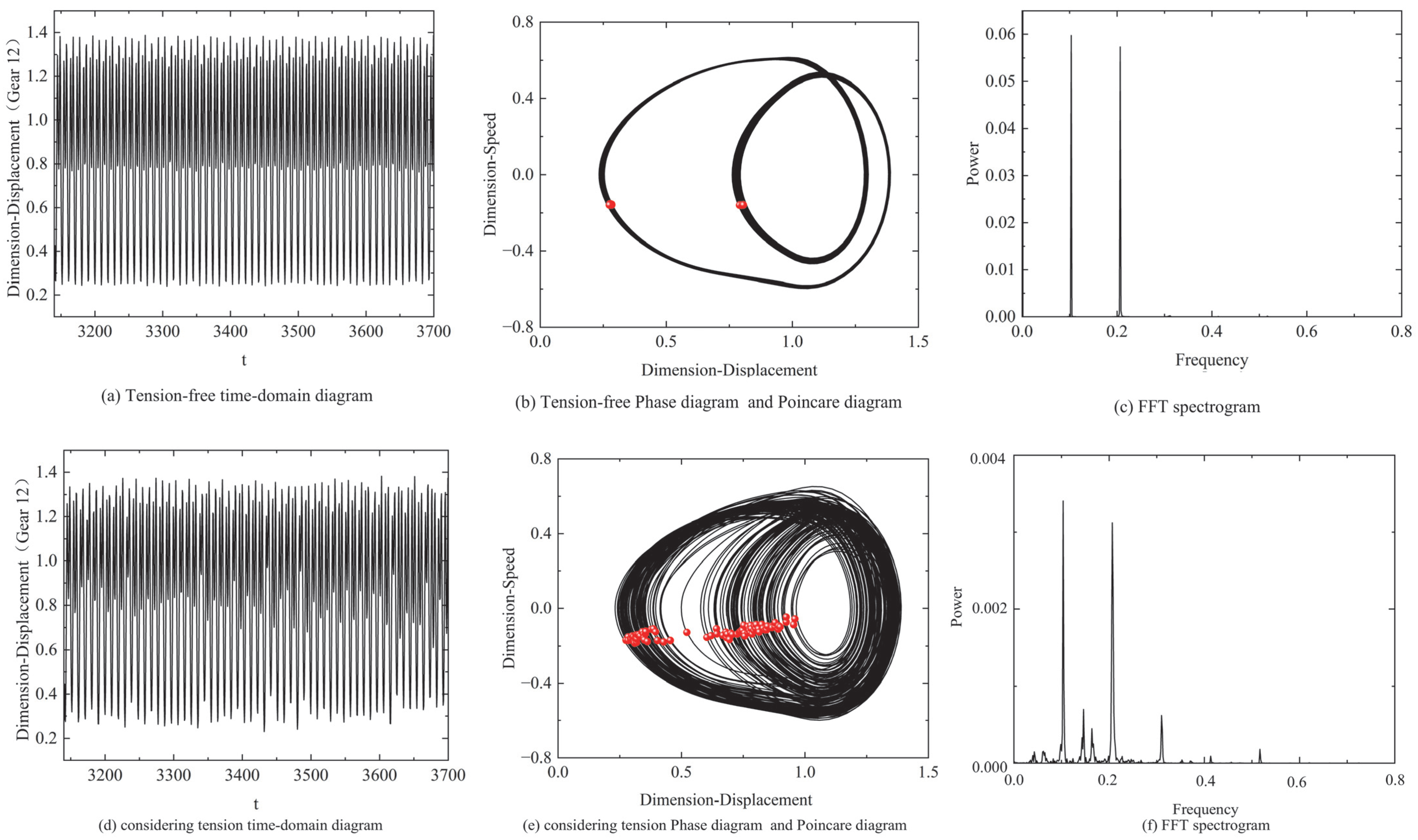
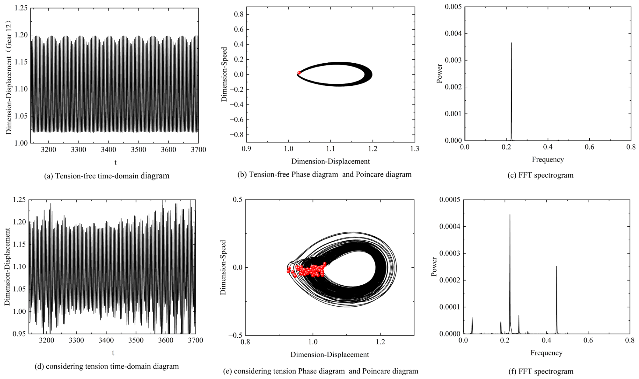
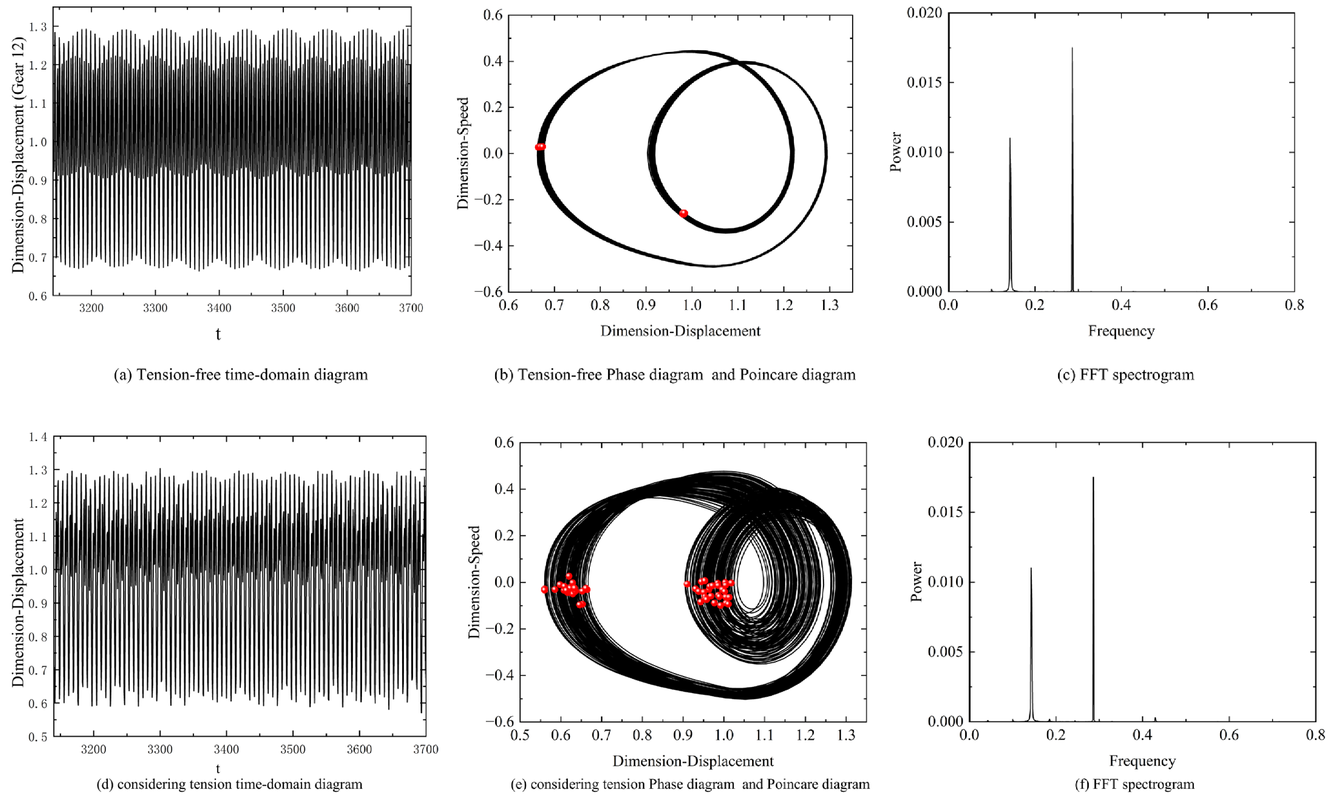
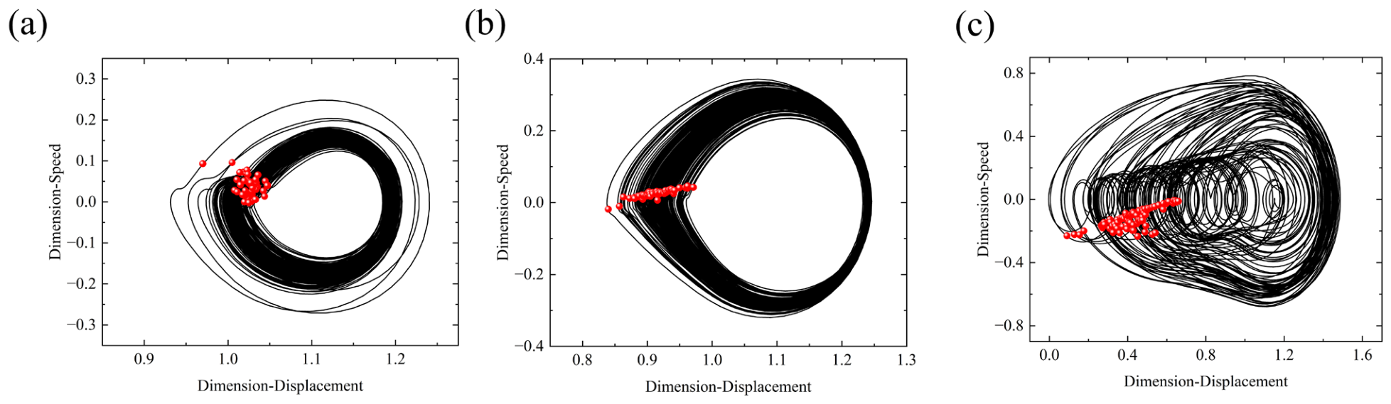
To further illustrate the influence of yarn tension across different frequencies, several key points are selected to plot the corresponding time-domain waveforms, phase portraits, Poincaré maps, and frequency spectra, as presented in Figure 9, Figure 10, Figure 11 and Figure 12.
As shown in Figure 9, when ω e = 0.57 , the time-domain waveforms under both conditions exhibit clear periodicity; the phase trajectories form closed loops resembling a circle, and the corresponding Poincaré maps display a single discrete red point. The distinction is that the intervention of tension causes the pre-existing smooth single-loop trajectory to evolve into a diffuse annular band structure with a certain “width”. This indicates that within the low-frequency regime ( 0.5 < ω e < 0.69 ), the introduction of tension accentuates the system’s nonlinearity without altering its global motion state. This observation is further corroborated by the FFT spectra. When yarn tension is neglected, the power spectrum presents a single sharp peak, indicating that the system is in a single-frequency periodic motion state. Upon incorporating yarn tension, several sub-peaks emerge alongside the dominant primary peak in the power spectrum, demonstrating that the introduction of tension amplifies the system’s nonlinearity, distorts the response waveform, and drives the system into a nonlinear periodic motion state.
As illustrated in Figure 10, without considering yarn tension fluctuations, the system undergoes an inverse period-doubling motion at ω e = 1.3 . The phase trajectory presents two nested, non-overlapping closed loops, and the Poincaré mapping points are distributed across two distinct positions. This indicates that within a complete evolutionary cycle, the system must traverse two different oscillatory trajectories before returning to its starting point. The existence of two primary peaks in the corresponding FFT spectrum further confirms that the system is in a period-2 motion state. Upon introducing yarn tension perturbations, the dynamic response of the system changes significantly. The phase trajectories begin to disperse outwardly, exhibiting large-amplitude scattering and diffusion within the phase space. Concurrently, multiple dense and continuous frequency components emerge around the dominant peaks in the corresponding FFT spectrum. The phenomena indicate that the intervention of tension shatters the original inverse period-doubling evolutionary path, inducing a sudden transition of the system from periodic motion to chaos, which significantly deteriorates the system’s stability.
As illustrated in Figure 11, when ω e = 1.41 and yarn tension is neglected, the system exhibits a standard period-1 steady-state response. Its time-domain waveform shows regular oscillations with constant amplitude; the phase trajectory forms a single, smooth, closed limit cycle, and the Poincaré mapping points coincide at a single isolated point. Correspondingly, the FFT spectrum displays a clear single-line spectrum, indicating that the system energy is highly concentrated at a single meshing frequency. When tension is considered, the time-domain plot exhibits irregular fluctuations. The phase trajectory deviates from a single limit cycle and evolves into an annular ribbon-shaped attractor with a certain width, while the Poincaré mapping points diffuse from an isolated single point into a scattered cluster of discrete points, exhibiting typical characteristics of quasi-periodic motion. Meanwhile, prominent sideband frequencies emerge on both sides of the primary frequency in the FFT spectrum. Figure 12 shows the case for ω e = 1.8 , where the evolutionary pattern is similar to that described above. These phenomena convincingly demonstrate that when the system operates at a high rotational speed, tension significantly increases the motion dimensionality and dynamic complexity, thereby driving the originally stable system toward chaos.
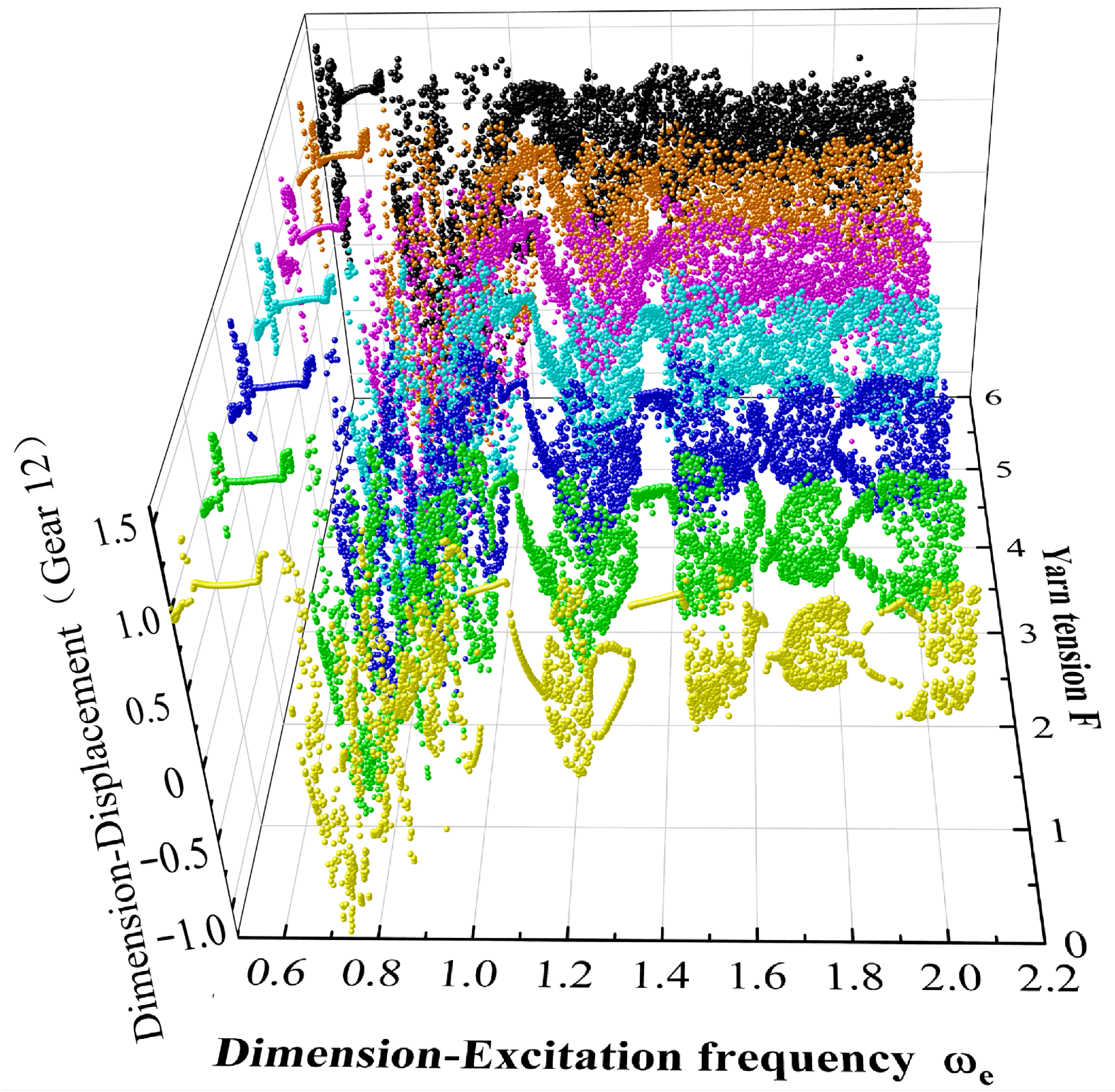
The preceding analysis demonstrates that yarn tension significantly amplifies the system’s nonlinear dynamic characteristics, thereby driving the gear system toward chaotic states. Consequently, the impact of varying tension levels on the system’s dynamic response is examined, as illustrated in Figure 13. It is observed that the critical tension is inversely proportional to the excitation frequency. Specifically, to ensure dynamic stability, the product of the tension and the excitation frequency must be maintained below a threshold of 4.5. These findings provide a theoretical basis for the strategic selection of mesh frequencies, effectively preventing chaotic motion and enhancing the overall stability of the gear transmission system.

4.2. Dynamic Response Analysis of Gear Systems Considering Tooth Surface Friction

The dynamic response of the system depends not only on external perturbations such as yarn tension but is also deeply constrained by internal nonlinear factors. As a typical endogenous nonlinear factor in gear systems, tooth surface friction undergoes an instantaneous directional reversal when the meshing point crosses the pitch point, generating a strong non-smooth excitation. Since yarn tension directly determines the dynamic load between the teeth, which in turn affects the amplitude and impact intensity of the friction force, merely considering load fluctuations is insufficient to comprehensively characterize the instability mechanism of the system. Based on the formulation of the tension-load mapping model, this paper further takes the friction coefficient μ as a variable, aiming to reveal the system evolutionary laws under the coupled effect of external tension and internal friction. The friction coefficient is determined based on empirical engineering values. Considering the semi-open gear transmission characteristic of the braiding machine, the friction coefficient between tooth surfaces typically ranges from 0.05 to 0.1. However, during the braiding process, fiber fragments from the yarn can easily penetrate the gear clearance and disrupt the lubricating film. Under extreme operating conditions such as lubrication failure or severe fiber contamination, the equivalent friction coefficient may rise to approximately 0.2. Therefore, this study investigates a range of friction coefficients from 0 to 0.2 to simulate the influence of different lubrication states on the nonlinear characteristics of the system.
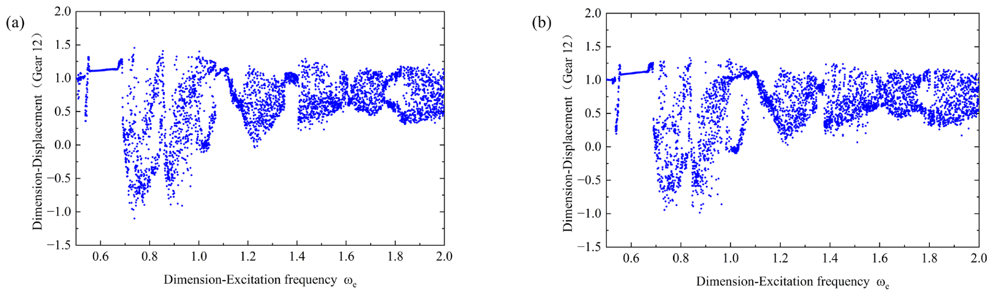
By comparing the bifurcation diagrams in Figure 8 and Figure 14, the analysis reveals that tooth surface friction makes a dual contribution to the dynamic evolution of the 88-spindle braiding machine transmission system. When ω e < 1.05 , the bifurcation paths of the high-friction system are clearer than those of the low-friction system, indicating enhanced systemic stability. This phenomenon occurs because the rotational speed of the system is relatively low at this stage; thus, the energy dissipation effect generated by frictional work dominates this specific frequency band. In this regime, the friction force acts as a strong damping term, thereby driving the system toward stability. Conversely, when ω e > 1.05 , the intervention of friction causes the system to drift toward chaos. This destabilization is primarily attributed to the unique directional reversal mechanism of the friction force across the pitch point, which serves as a strong nonlinear impulsive excitation, disrupting the periodic evolutionary laws of the system and resulting in instability. This “perturbation–damping” competition mechanism ultimately dictates the stability performance of the system under different excitation frequencies in the presence of friction.
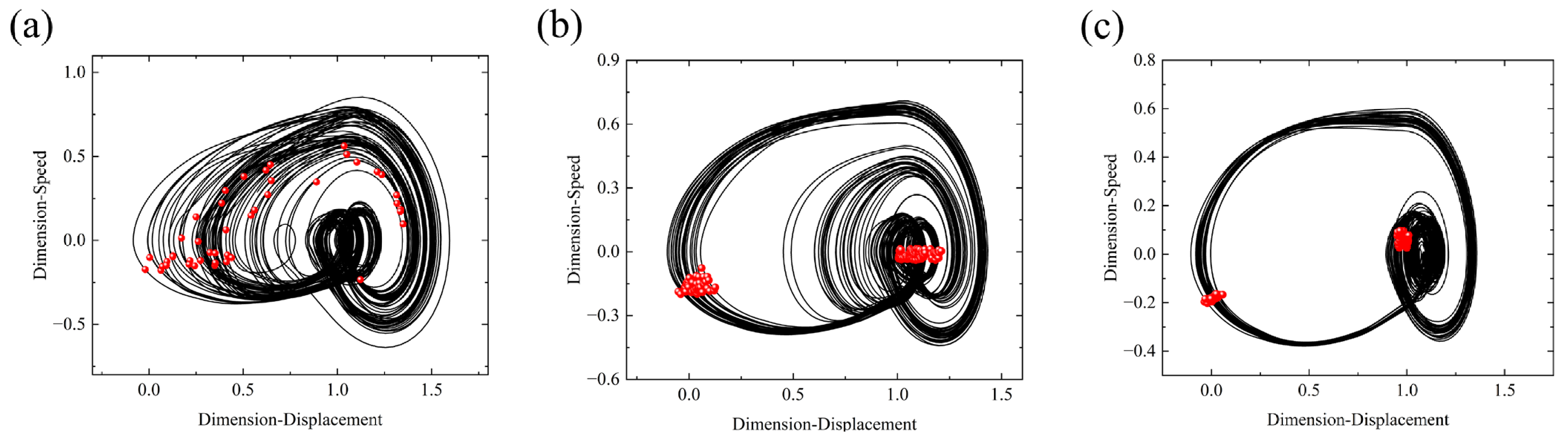
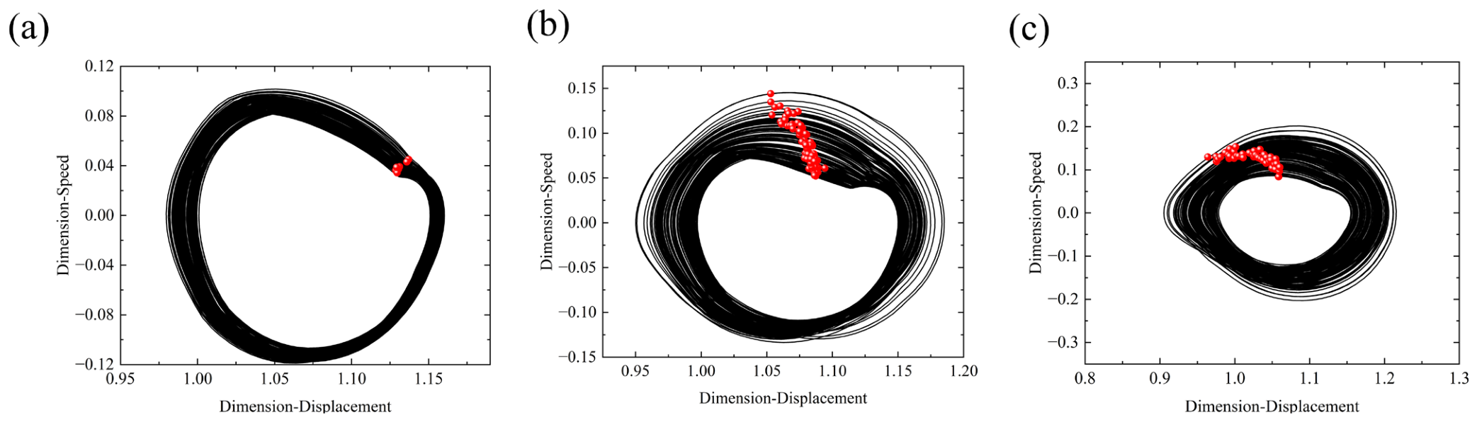
To clearly demonstrate the influence of the friction coefficient on the system under different frequencies, several specific points within the regions where friction exerts a significant impact are selected. The phase portraits and Poincaré maps of the system at these discrete points are plotted, as shown in Figure 15, Figure 16, Figure 17 and Figure 18.
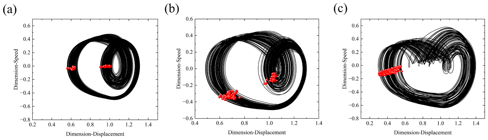
As illustrated in Figure 15, which shows the response states of the system under different friction coefficients at the dimensionless frequency ω e = 1.02 , the analysis indicates that as the friction coefficient   μ increases from 0 to 0.2, the system undergoes a transition from disorder to stable periodic motion. When μ = 0 , the phase trajectory diffuses outwardly, and the corresponding Poincaré mapping points are highly discrete. In contrast, after introducing the friction coefficient, the system trajectory exhibits a conspicuous convergence, and the mapping points evolve into two clear point clusters, marking the system’s entry into a stable period-2 motion state. This evolutionary process reveals that within this frequency band, the intervention of tooth surface friction provides a critical energy dissipation mechanism, acting as a damping term.
Figure 16, Figure 17 and Figure 18 correspond to the dimensionless frequencies ω e = 1.1, 1.4, 1.8, respectively. A comparative analysis reveals that as the friction coefficient increases, the phase trajectories of the system exhibit an expansion in both the displacement and velocity dimensions. This indicates that within this specific frequency band, the introduction of friction amplifies the fluctuation amplitude of the system’s total energy rather than causing dissipation. This phenomenon occurs because, with the escalation of frequency, the instantaneous directional reversal impact of the friction force at the pitch point is no longer counteracted by damping. Consequently, the characteristics of non-smooth excitation become dominant, significantly intensifying the system’s nonlinearity and driving the system toward a chaotic state.
Through the analysis, it can be concluded that the friction force exerts a dual dynamic effect on the gear system of the braiding machine. In the low-frequency regime ( ω e < 1.05), the sliding velocity of the tooth surface is relatively low, and the friction force primarily plays an “energy dissipation” role, manifesting as a strong damping constraint that stabilizes the system into a periodic state. However, once the excitation frequency exceeds the critical threshold ( ω e > 1.05), the frequency of the friction directional reversal impact at the pitch point increases accordingly, and its attribute as a “nonlinear impulsive excitation” takes dominance. This non-smooth excitation deeply couples with the dynamic loads, amplifying the system’s nonlinear instability and thereby inducing the system to evolve toward a chaotic state.
While this study reveals the nonlinear dynamic evolution of the gear transmission system in braiding machines, certain limitations remain due to model simplifications and the inherent complexity of actual engineering applications.
  • Deviation caused by the ideal symmetry assumption: To improve computational efficiency and highlight the fundamental dynamic mechanisms, this model assumes perfect geometric and parametric symmetry across the four quadrants. However, in actual industrial operation, factors such as manufacturing tolerances, assembly errors, and non-uniform wear resulting from long-term cyclic operation can introduce slight discrepancies across these quadrants. Such asymmetries may induce more complex localized vibrational responses.
  • Simplification of the friction nonlinearity model: The current model is analyzed based on a specific friction coefficient. However, in practical operations, friction exhibits strong stochastic and time-varying characteristics due to fluctuations in lubrication conditions and temperature. This study has not fully incorporated the coupling effects of these stochastic factors.
  • Limitations of the pure torsional model: The model simplifies the gear system into pure torsional vibrations, neglecting the coupling effects of shaft bending, radial displacements, and gear bearing support stiffness on dynamic behavior. This simplification may mask certain high-order nonlinear dynamic characteristics.
In view of the limitations, future work will be devoted to developing a high-fidelity, multi-degree-of-freedom dynamic model that incorporates asymmetric parameters and stochastic perturbations. This will allow for a more in-depth exploration of the comprehensive effects of these practical factors on the chaotic boundaries and vibration transmission characteristics of gear systems under complex industrial operating conditions.

5. Conclusions

This paper takes the gear system of a radial 88-carrier braiding machine as the research object. By meticulously accounting for actual operating conditions, this paper formulates a refined tension-load mapping relationship. On this basis, the nonlinear dynamic characteristics of the system under the coupled effect of yarn tension and tooth surface friction are investigated. The results are as follows:
  • Yarn tension enhances frictional nonlinearities, promoting chaotic behavior within the system. Below a dimensionless frequency of 0.69, the system maintains stable period-one motion due to lower kinetic energy. Above this threshold, chaotic regimes supersede the reverse period-doubling bifurcation windows, and periodic motion evolves into quasi-periodic motion. Therefore, careful attention must be paid to the destabilizing effects of tension fluctuations within this frequency range.
  • A nonlinear coupling exists between yarn tension and mesh frequency. The system exhibits stable dynamic behavior when the product of these two parameters is below 4.5; conversely, exceeding this threshold drives the system toward chaos, resulting in a substantial loss of transmission precision.
  • Friction plays a dual role as both an energy dissipator and a nonlinear exciter depending on the frequency. For ω e < 1.05, damping dissipation prevails, and moderate friction enhancement can suppress chaotic behavior. However, for ω e > 1.05, the instantaneous directional reversal of friction at the pitch point induces strong, non-smooth impulsive excitations, which dominate the system dynamics. In this regime, higher friction intensifies nonlinear oscillations, driving quasi-periodic motion toward chaos; thus, it is advisable to minimize friction for operations in this frequency range.

Author Contributions

Conceptualization, Z.Y. and L.Y.; methodology, Z.Y. and L.Y.; software, Z.Y.; formal analysis, Z.Y.; writing—original draft preparation, Z.Y.; writing—review and editing, Z.Y. and L.Y.; supervision, L.Y.; data curation, Z.Y., C.W. and D.L. All authors have read and agreed to the published version of the manuscript.

Funding

This project was supported by the major enterprise project named “Application of AI in Toxic and Harmful Gas Detection in Coal Mines” (grant number KYH25079), “Development of Advanced Auxiliary System for Underground Trackless Rubber-Tired Vehicles” (grant number KYH24072), and supported by “The Talent Introduction Project of Lingling Yao“ (grant number KYY23016).

Data Availability Statement

The data presented in this study are contained within the article.

Acknowledgments

The authors would like to thank the anonymous reviewers for their valuable comments and suggestions.

Conflicts of Interest

The authors declare that this study have received funding from major enterprise project “Application of AI in Toxic and Harmful Gas Detection in Coal Mines”, “ Development of Advanced Auxiliary System for Underground Trackless Rubber-Tired Vehicles” and “The Talent Introduction Project of Lingling Yao”. The funder was not involved in the study design, collection, analysis, interpretation of data, the writing of this article or the decision to submit it for publication.

References

  1. Mouritz, A.P.; Bannister, M.K.; Falzon, P.J.; Leong, K.H. Review of applications for advanced three-dimensional fibre textile composites. Compos. Part A Appl. Sci. Manuf. 1999, 30, 1445–1461. [Google Scholar] [CrossRef] [Scilit]
  2. Zhou, Q.; Jiao, Y.N.; Li, J.L. Process parameters design of three-dimensional braiding preforms. J. Tiangong Univ. 2004, 23, 15–17. [Google Scholar]
  3. Du, S.Y. Advanced composite materials and aerospace engineering. Acta Mater. Compos. Sin. 2007, 24, 1–12. [Google Scholar] [CrossRef]
  4. Zhang, M.Q.; Zou, T.; Huang, Y.C.; Yang, G.G.; Zu Wang, W.; Zhou, J.M.; Wang, L.; Chen, F.; Xie, H. Braided thin-walled biodegradable ureteral stent: Preliminary evaluation in a canine model. Int. J. Urol. 2014, 21, 401–407. [Google Scholar] [CrossRef] [Scilit] [PubMed]
  5. Kyosev, Y. Advances in Braiding Technology: Specialized Techniques and Applications; Woodhead Publishing: Oxford, UK, 2016. [Google Scholar]
  6. Li, S.; Shan, Z.; Du, D.; Zhan, L.; Guo, Z.; Du, W.; Wu, X. Effect of processing parameters on friction and damage of carbon yarn during three-dimensional weaving. J. Text. Inst. 2022, 113, 1123–1132. [Google Scholar]
  7. Hu, X.T.; Zhang, Y.J.; Meng, Z.; Sun, B.; Guo, X.H. Modeling and influence about speed of released-yarn in braiding spindles on yarn tension. J. Text. Res. 2017, 38, 111–117. [Google Scholar] [CrossRef]
  8. Hu, X.; Zhang, Y.; Meng, Z.; Sun, Y. Tension modeling and analysis of braiding carriers during radial-direction and axial-direction braiding. J. Text. Inst. 2019, 110, 1190–1201. [Google Scholar] [CrossRef] [Scilit]
  9. Peng, L.H.; Liu, J.T.; Li, Y.; Qi, Y.B.; Li, J.Q.; Mao, M.Q. Contact yarn tension measurement method based on convolutional filtering. J. Text. Res. 2023, 44, 73–80. [Google Scholar] [CrossRef]
  10. Tate, J.S.; Kelkar, A.D.; Whitcomb, J.D. Effect of braid angle on fatigue performance of biaxial braided composites. Int. J. Fatigue 2006, 28, 1239–1247. [Google Scholar] [CrossRef] [Scilit]
  11. Kahraman, A.; Singh, R. Non-linear dynamics of a spur gear pair. J. Sound Vib. 1990, 142, 49–75. [Google Scholar] [CrossRef] [Scilit]
  12. Vaishya, M.; Singh, R. Analysis of periodically varying gear mesh systems with Coulomb friction using Floquet theory. J. Sound Vib. 2001, 243, 525–545. [Google Scholar] [CrossRef] [Scilit]
  13. Cui, Y.; Liu, Z.; Wang, Y.; Ye, J. Nonlinear dynamic of a geared rotor system with nonlinear oil film force and nonlinear mesh force. J. Vib. Acoust. 2012, 134, 041001–041008. [Google Scholar] [CrossRef] [Scilit]
  14. Bu, H.; Li, J.; Guo, J.; Gao, Z.; Zhao, Y. Establishment of theoretical model and dynamic analysis of gear meshing force for the multi-gear driving system considering the effect of friction. Eng. Fail. Anal. 2025, 171, 109382. [Google Scholar] [CrossRef] [Scilit]
  15. Hu, Z.; Tang, J.; Wang, Q.; Chen, S.; Qian, L. Investigation of nonlinear dynamics and load sharing characteristics of a two-path split torque transmission system. Mech. Mach. Theory 2020, 152, 103955. [Google Scholar] [CrossRef] [Scilit]
  16. Fang, Y.X.; Ding, Q.; Zhang, W. Non-linear dynamic features of a steering gear system with backlashes. J. Vib. Shock 2016, 35, 29–34. [Google Scholar] [CrossRef]
  17. Hua, Z.F.; Zhao, R.Z. Calculation Method of Coupling Effect of Tooth Surface Friction and Tooth Root Cracking in Planetary Wheel Systems for Wind Turbine Gearboxes. Acta Energiae Solaris Sin. 2022, 43, 287–293. [Google Scholar] [CrossRef]
  18. Xu, F.; Liu, W.B.; Zhang, Q.; Li, Z.H.; Zhu, C.C. Nonlinear Dynamics Analysis of the Wind Turbine Gear Transmission System Considering Friction Effect. J. Mech. Transm. 2023, 47, 31–42. [Google Scholar] [CrossRef]
  19. Du, Y.B.; Gao, J.S.; Wu, L.J.; An, P. Analysis of Nonlinear Dynamic Characteristics of Planetary Gear with Friction. Modul. Mach. Tool Autom. Manuf. Tech. 2025, 61, 28–34. [Google Scholar] [CrossRef]
  20. Zhang, Y.J.; Meng, Z.; Sun, Y.Z. Dynamic modeling and chaotic analysis of gear transmission system in a braiding machine with or without random perturbation. Shock Vib. 2016, 2016, 8457645. [Google Scholar] [CrossRef] [Scilit]
  21. Yao, L.L.; Meng, Z.; Bu, J.; Sun, Y. Investigation of nonlinear characteristics of a gear transmission system in a braiding machine with multiple excitation factors. Shock Vib. 2020, 2020, 2747204. [Google Scholar] [CrossRef] [Scilit]
  22. Yao, L.L.; Du, C.; Lu, Y. Investigation of nonlinear characteristics of a gear transmission system in a multi-ring braiding machine considering contact temperature. J. Ind. Text. 2025, 55, 15280837251323209. [Google Scholar] [CrossRef] [Scilit]
  23. Yao, L.L.; Meng, Z.; Bu, J.; Sun, Y. Non-linear dynamic feature analysis of a multiple-stage closed-loop gear transmission system for 3D circular braiding machine. Symmetry 2020, 12, 1788. [Google Scholar] [CrossRef] [Scilit]
  24. Liu, Y.B.; Sun, Z.J.; Mei, Y. Nonlinear Dynamics of Closed-Loop Gear System of Three-Dimensional Braiding Machine. Manuf. Autom. 2024, 46, 168–176. [Google Scholar]
  25. Sun, Z.; Liu, Y.B. Bifurcation and chaos analysis of the closed-loop gear system of the 3D braiding machine. J. Mech. Sci. Technol. 2024, 38, 1669–1681. [Google Scholar] [CrossRef] [Scilit]
  26. Cui, C.; Jiang, H.; Zhang, X.F.; Ding, H. Fault monitoring analysis of gear with time-varying transfer path. Mach. Tool Hydraul. 2025, 53, 1–8. [Google Scholar] [CrossRef] [Scilit]
  27. Lin, J.; Parker, R.G. Planetary gear parametric instability caused by mesh stiffness variation. J. Sound Vib. 2002, 249, 129–145. [Google Scholar] [CrossRef] [Scilit]
  28. Guo, Z.; Meng, Z.; Cai, G.; Zhang, Y. Modeling and Optimizing for Fiber Bundle Tension in Braiding Carrier. Polym. Compos. 2026. [Google Scholar] [CrossRef] [Scilit]
  29. Kahraman, A.; Blankenship, G.W. Experiments on nonlinear dynamic behavior of an oscillator with clearance and periodically time-varying parameters. J. Appl. Mech. 1997, 64, 217–226. [Google Scholar] [CrossRef] [Scilit]
  30. Kahraman, A.; Blankenship, G.W. Interactions between commensurate parametric and forcing excitations in a system with clearance. J. Sound Vib. 1996, 194, 317–336. [Google Scholar] [CrossRef] [Scilit]
  31. Blankenship, G.W.; Kahraman, A. Steady state forced response of a mechanical oscillator with combined parametric excitation and clearance type non-linearity. J. Sound Vib. 1995, 185, 743–765. [Google Scholar] [CrossRef] [Scilit]
Figure 1. Internal structure of the transmission part.
Symmetry 18 01234 g001
Figure 2. Schematic diagram of the working principle of the radial 3D braiding machine.
Symmetry 18 01234 g002
Figure 3. Gear model: (a) radial braiding machine gear distribution. (b) gear dynamics model.
Symmetry 18 01234 g003
Figure 4. (a) Spur gear mesh division. (b) Time-varying meshing stiffness of braiding machine gear pair.
Symmetry 18 01234 g004
Figure 5. (a) Schematic of braiding. (b) force analysis diagram of the yarn. (c) schematic of a single spindle. (d) force analysis diagram of the spindle. (e) spindle trajectory diagram.
Symmetry 18 01234 g005
Figure 6. Meshing friction.
Symmetry 18 01234 g006
Figure 7. Without considering yarn tension: (a) bifurcation diagram. (b) maximum Lyapunov exponent diagram.
Symmetry 18 01234 g007
Figure 8. Considering yarn tension: (a) bifurcation diagram. (b) maximum Lyapunov exponent diagram.
Symmetry 18 01234 g008
Figure 9. Kinematics of the system motion state at ω e = 0.57.
Symmetry 18 01234 g009
Figure 10. Kinematic analysis of the system state at ω e = 1.3.
Symmetry 18 01234 g010
Figure 11. Kinematic analysis of the system state at ω e = 1.41.
Symmetry 18 01234 g011
Figure 12. Kinematic analysis of the system state at ω e = 1.8.
Symmetry 18 01234 g012
Figure 13. Bifurcation diagram of the gear transmission system under varying yarn tension. The different colors in the figure correspond to the yarn tension values on the y-axis.
Symmetry 18 01234 g013
Figure 14. Friction bifurcation diagram: (a)   μ = 0.1 . (b) μ = 0.2 .
Symmetry 18 01234 g014
Figure 15. ω e = 1.02 : (a) μ = 0. (b) μ = 0.1. (c) μ = 0.2.
Symmetry 18 01234 g015
Figure 16. ω e = 1.1: (a) μ = 0. (b) μ = 0.1. (c) μ = 0.2.
Symmetry 18 01234 g016
Figure 17. ω e = 1.4: (a) μ = 0. (b) μ = 0.1. (c) μ = 0.2.
Symmetry 18 01234 g017
Figure 18. ω e = 1.8: (a) μ = 0. (b) μ = 0.1. (c) μ = 0.2.
Symmetry 18 01234 g018
Table 1. Basic parameters of the closed-loop gear transmission system.
Gear 1Gear 2
Modulus/mm44
Number of teeth/z3030
Tooth width/mm1010
pressure angle (°)2020
Displacement coefficient0.50470.5047
Moment of inertia (kg·m2)1.8 × 10 3 1.8 × 10 3
Disclaimer/Publisher’s Note: The statements, opinions and data contained in all publications are solely those of the individual author(s) and contributor(s) and not of MDPI and/or the editor(s). MDPI and/or the editor(s) disclaim responsibility for any injury to people or property resulting from any ideas, methods, instructions or products referred to in the content.