1. Introduction
High-speed jets and intense shock waves released during cavitation bubble collapse are the core causes of cavitation erosion damage to flow components of fluid machinery, such as water turbines, pumps, and valves [
1,
2]. Semi-cylindrical grooves, such as welds, joints, and cracks, commonly exist on the surface of hydraulic flow passage components [
3,
4,
5]. Such structures possess geometric features of continuous curvature and smooth transition between the groove mouth and the flat wall, which significantly alter the local flow field structure and bubble collapse behavior, making them high-incidence areas of cavitation erosion damage in hydraulic machinery. In addition, cavitation erosion also widely occurs in the field of fire engineering [
6]. Therefore, investigating the dynamic characteristics of cavitation bubble collapse near semi-cylindrical grooves has important engineering application value and scientific significance for optimizing the anti-cavitation design of hydraulic machinery and extending equipment service life. In this paper, the collapse characteristics of cavitation bubbles near a semi-cylindrical groove were studied in detail using a high-speed photography experimental system.
The collapse behavior of cavitation bubbles near various rigid walls has been widely concerned. According to the geometric structure of the wall, it can be divided into flat walls [
7,
8,
9,
10,
11,
12] and curved walls [
13,
14,
15,
16,
17,
18,
19,
20,
21]. For the research on the collapse behavior of cavitation bubbles near flat walls, Li et al. [
7] found, based on high-speed photography experiments, that with the increase of the bubble–flat wall distance, the collapse morphology of cavitation bubbles changes from an eccentric shape to an elliptical egg shape, and finally collapses spherically. Brujan et al. [
8] found experimentally that when the cavitation bubble is far away from the flat wall, the jet penetrates the bubble to form an annular bubble that collapses radially, forming a crescent shape during the second collapse. Brujan et al. [
9] combined high-speed photography experiments and numerical simulation methods, and found four typical cases of conventional jets, needle jets, and co-directional double jets by changing the bubble–flat wall distance. Lindau et al. [
10] found experimentally that when the cavitation bubble is close to the flat wall, the jet passes through the bubble to form a vortex ring, and obvious splashing occurs after the jet hits the wall. With the increase of the bubble–wall distance, the formation of the vortex ring becomes more obvious. Xiang et al. [
11] observed the vortex ring generated after the collapse of cavitation bubbles near the flat wall through experiments and simulations, leaving multi-focus annular damage on the wall. The results show that the higher the velocity of the bubble collapse jet, the greater the velocity and width of the vortex ring. During the rebound stage of cavitation bubble collapse, Brujan [
9] and Zhang [
12] also found the reflection flow, and the results show that the reflection flow will make the cavitation bubble move away from the wall.
For the research on cavitation bubble characteristics near curved walls, factors such as the geometric structure, curvature of the wall, and the distance between the bubble and the wall have a significant impact on the cavitation bubble collapse behavior. Tomita et al. [
13] studied the dynamic characteristics of cavitation bubble movement, deformation, and collapse jet near a curved wall. The results show that when the cavitation bubble and the curved wall have the same scale, the movement of the cavitation bubble is significantly affected by the curvature. Cui et al. [
14] found through experimental observation and numerical simulation that a single cavitation bubble near a trapezoidal pit changes from an egg shape to two drop-shaped clouds during collapse. Kim et al. [
15] found experimentally that when the bubble–wall distance is small, the cavitation bubble collapses near the wall with multiple trapezoidal pits and splits into two smaller cavitation bubbles, one of which is far away from the wall and the other is close to the wall. Shan et al. [
16] studied the case of small bubble–wall distance, and the results show that with the increase of pit curvature, the collapse jet velocity of cavitation bubbles gradually decreases. Shervani-Tabar and Rouhollahi et al. [
17] carried out a more detailed numerical simulation study and found that with the increase of pit curvature, the collapse jet velocity of cavitation bubbles decreases, the bubble period becomes longer, and the bubble centroid movement becomes more significant. Zeng et al. [
18] studied the collapse morphology and jet characteristics of cavitation bubbles near complex walls, such as plane symmetric rectangular grooves and wedge-shaped grooves, in detail by means of experiments and numerical simulations. It was found that the bubble centroid has a significant transition during the jet formation stage, and the narrowing of the groove width enhances the jet intensity and centroid movement speed. Andrews et al. [
19,
20] further extended the research to asymmetric cases and studied the influence of rectangular grooves on the direction of the cavitation bubble collapse jet by using numerical simulation and experimental methods. It was found that with the increase of groove depth, the maximum deflection angle of the jet direction has no obvious change. With the increase of the distance between the bubble and the groove, the maximum deflection angle of the jet decreases. Zhou et al. [
21] compared the pressure distribution of curved walls and flat walls through experiments. The results show that the existence of curvature increases the unevenness of the wall pressure, and the degree of unevenness increases with the increase of curvature.
In summary, numerous scholars have conducted extensive research on the collapse morphology and jet characteristics of cavitation bubbles near various wall structures, including flat walls, rectangular grooves, wedge-shaped grooves, pits, and slits. However, studies focusing on the collapse morphology and movement characteristics of cavitation bubbles near semi-cylindrical grooves remain relatively limited. Compared with the aforementioned structures, semi-cylindrical grooves possess two essential geometric features that may fundamentally alter bubble collapse dynamics. First, the continuous uniform curvature feature, which differs from the sharp corners of rectangular grooves and the discrete curvature changes of pits, exerts an axial guiding effect on the collapse flow field. Second, the smooth transition feature between the groove mouth and the adjacent flat wall, which avoids flow separation and pressure mutation at the groove mouth of rectangular grooves, forms a composite flow field effect of the groove curvature constraint and flat wall constraint.
Existing studies have not systematically revealed the jet directionality, three-dimensional vortex ring evolution, pressure loading distribution, and bubble migration characteristics of cavitation bubbles near semi-cylindrical grooves. In particular, there is a lack of quantitative research on the dynamic behavior of bubbles at asymmetric positions, and no mapping relationship between dimensionless parameters and collapse modes has been established. Most existing studies adopt single-view high-speed photography, which can only observe the two-dimensional planar morphology evolution of bubbles and cannot fully capture three-dimensional vortex ring structures and spatial migration characteristics. This work constructs a dual-view synchronous high-speed photography experimental system to simultaneously acquire front and top images of bubble collapse processes, systematically investigates the collapse morphology and vortex ring evolution characteristics of cavitation bubbles at symmetric positions near semi-cylindrical grooves and the migration laws of bubbles at asymmetric positions, establishes a partition map of dimensionless parameters and collapse modes, reveals the regulation mechanism of semi-cylindrical grooves on bubble collapse behavior, and provides experimental support for improving the theory of cavitation bubble collapse near complex wall surfaces.
2. Experimental System and Physical Model
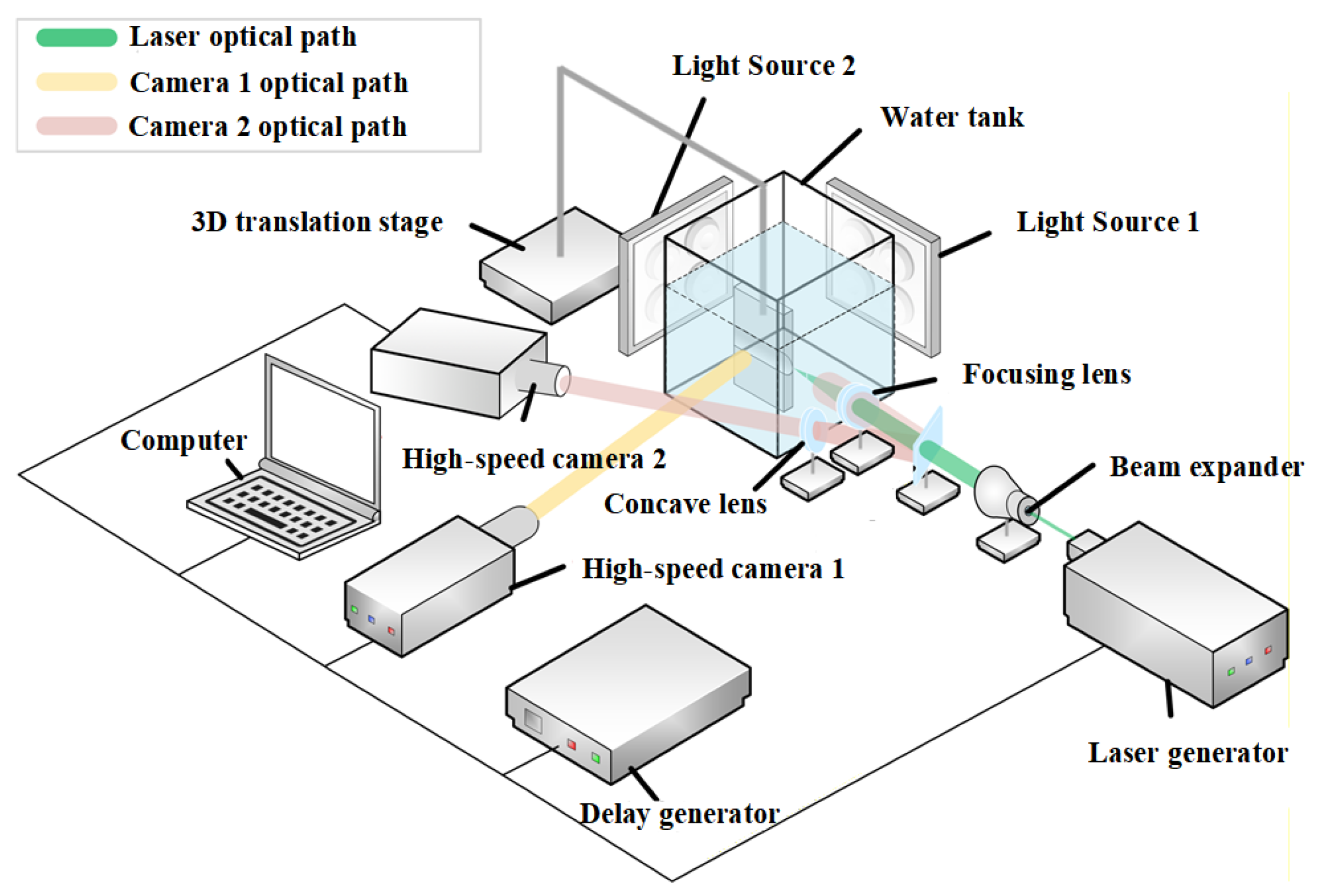
Figure 1 show the schematic diagram and physical diagram of the high-speed photography experimental system, respectively. The main equipment of the experimental system includes two high-speed cameras, a delay generator, a laser generator, a focusing lens, a water tank, a concave lens, a light source, etc. Among them, two high-speed cameras are used to record the complete process of cavitation bubble dynamic behavior near the groove model. High-speed camera 1 takes a top view, and high-speed camera 2 adjusts the optical path through the installed concave lens and filter to take a front view. Two i-speed 510 high-speed cameras (iXcameras, Essex, UK) are used for synchronous recording, with an identical camera exposure time (shutter time) of 1 μs and a frame rate of 100,000 fps. The pixel-to-length calibration coefficients (spatial resolution) are calibrated to 0.0625 mm per pixel for the front-view camera and 0.0286 mm per pixel for the top-view camera. The water tank is filled with deionized water, and the size of the water tank is 150 × 150 × 150 mm
3. The laser generator is used to induce cavitation bubble generation, and the delay generator is used to coordinate the synchronous operation of the high-speed camera and the laser generator. The beam expander is used to amplify the laser beam, the focusing lens focuses the laser precisely on the cavitation bubble growth point, and the light source makes the picture clear. The three-dimensional displacement translation stage can adjust the position of the experimental material to carry out parametric experiments. In this paper, the shooting speed of both high-speed cameras is 1.0 × 10
5 frames per second. The laser energy is adjusted by changing the working voltage of the laser generator, thereby regulating the cavitation bubble size. The energy range of the laser generator is 0~100 mJ. The experimental ambient pressure is atmospheric pressure, and deionized water is used as the experimental medium. In addition, the machining precision of the groove radius is ±0.01 mm, and the surface roughness of the groove wall and adjacent flat wall is controlled within 0.8 μm. As for the phase transition effect, under the experimental conditions of this study, the duration of the first cycle of the cavitation bubble is extremely short, and the water temperature is controlled at 25 ± 0.5 °C. The phase transition inside the bubbles is negligible, which exerts little influence on the overall collapse, migration, and vortex ring evolution of cavitation bubbles. According to previous work by Tomita et al., boundary confinement effects can be eliminated when the tank side length exceeds 10 times the maximum bubble radius [
13], and the water tank adopted in this experiment satisfies this requirement. Furthermore, calculations based on the acoustic propagation law presented by Lindau et al. demonstrate that pressure waves reflected from the tank walls return only after the completion of the primary bubble collapse, thereby causing no interference to experimental observations [
10].
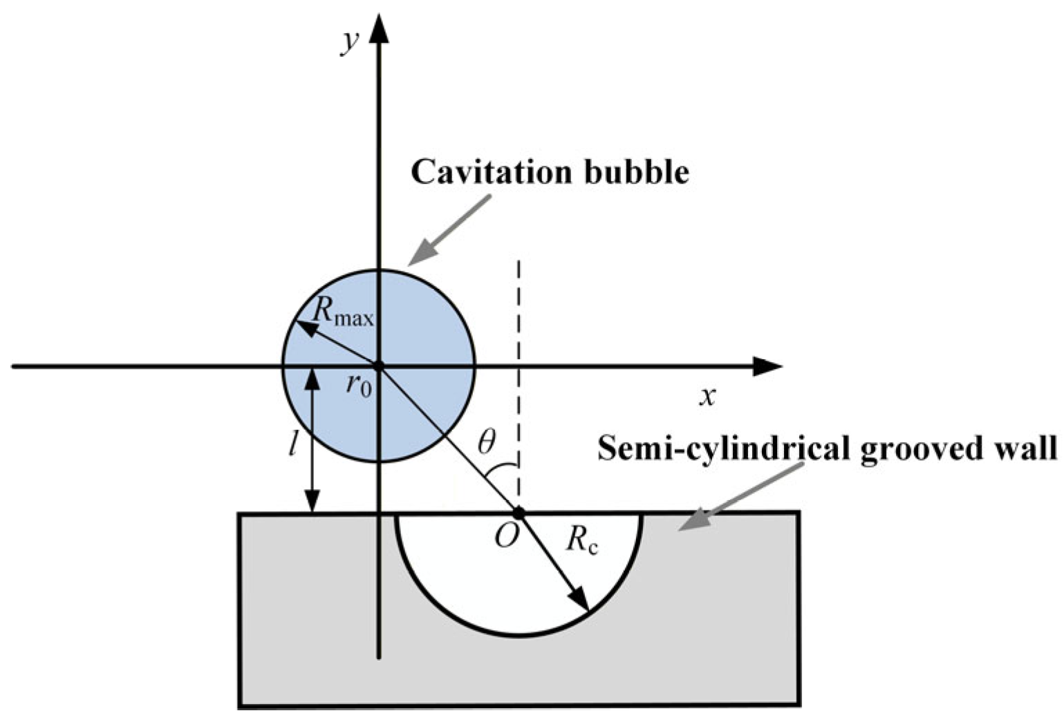
Figure 2 presents the physical model and parameter definitions. A Cartesian coordinate system is constructed with the initial centroid of the cavitation bubble
r0 as the origin, with the
x-axis pointing horizontally to the right and the
y-axis pointing vertically upward. This coordinate system serves as the unified reference frame for quantifying bubble centroid displacement, conducting error analysis, and verifying experimental repeatability.
O denotes the center of the semi-cylindrical groove,
l is the vertical distance from the bubble initial centroid
r0 to the groove center
O,
Rc is the groove radius, and
Rmax is the maximum radius of a cavitation bubble in an unbounded flow field. The bubble azimuthal angle
θ is defined as the angle between the vertical symmetry axis passing through
O and the line connecting
O to
r0. For the convenience of subsequent analysis, the displacement distance of the bubble centroid is denoted by
S, which is defined as follows:
In the formula, Δx and Δy denote the displacement components of the bubble centroid along the x-axis and y-axis, respectively.
The error analysis of experimental results is organized as follows. The spatial resolution of the high-speed images is 0.048 mm per pixel in both the
x and
y directions. Therefore, the minimum error in displacement distance of the bubble centroid (∆
Serr) can be expressed as:
Here, ∆xerr and ∆yerr are the distance errors in the x-axis and y-axis directions, respectively.
To ensure the reliability of the experimental system and the reproducibility of the observed phenomena, 10 replicate validation experiments were conducted under a constant laser voltage to generate cavitation bubbles with a maximum radius of
Rmax = 1.60 mm, which is presented as a typical example to demonstrate the experimental consistency. Statistical data were collected for the maximum radii of the laser-induced bubbles, and their mean value and standard deviation were calculated to quantify the variability of bubble generation. The detailed measurement data and corresponding error indicators are provided in
Table 1.
As shown in
Table 1, the maximum bubble radius shows consistently low variability across repeated experiments. Its standard deviation is 1.69% of the mean value, which demonstrates excellent repeatability of bubble generation. These results collectively validate the reliability of the experimental system.
To simplify the mathematical model and describe the dynamic behavior of the bubble under different conditions more accurately, the dimensionless radius (
R*), dimensionless distance (
l*), and dimensionless time (
T*) are defined as follows:
where
t is the time calculated from the inception of the cavitation bubble, and
T0 is the duration from the inception of the cavitation bubble to the end of the first collapse. In this paper, the parameter values are
l* = 0.3~3.3,
R* = 0.5~3.0, and
Rc = 1.5 mm. A total of 157 sets of experimental data were obtained. Every operating condition involved in this paper was repeated no less than three times, and key representative test cases were repeated over five times to guarantee reliable experimental outcomes.
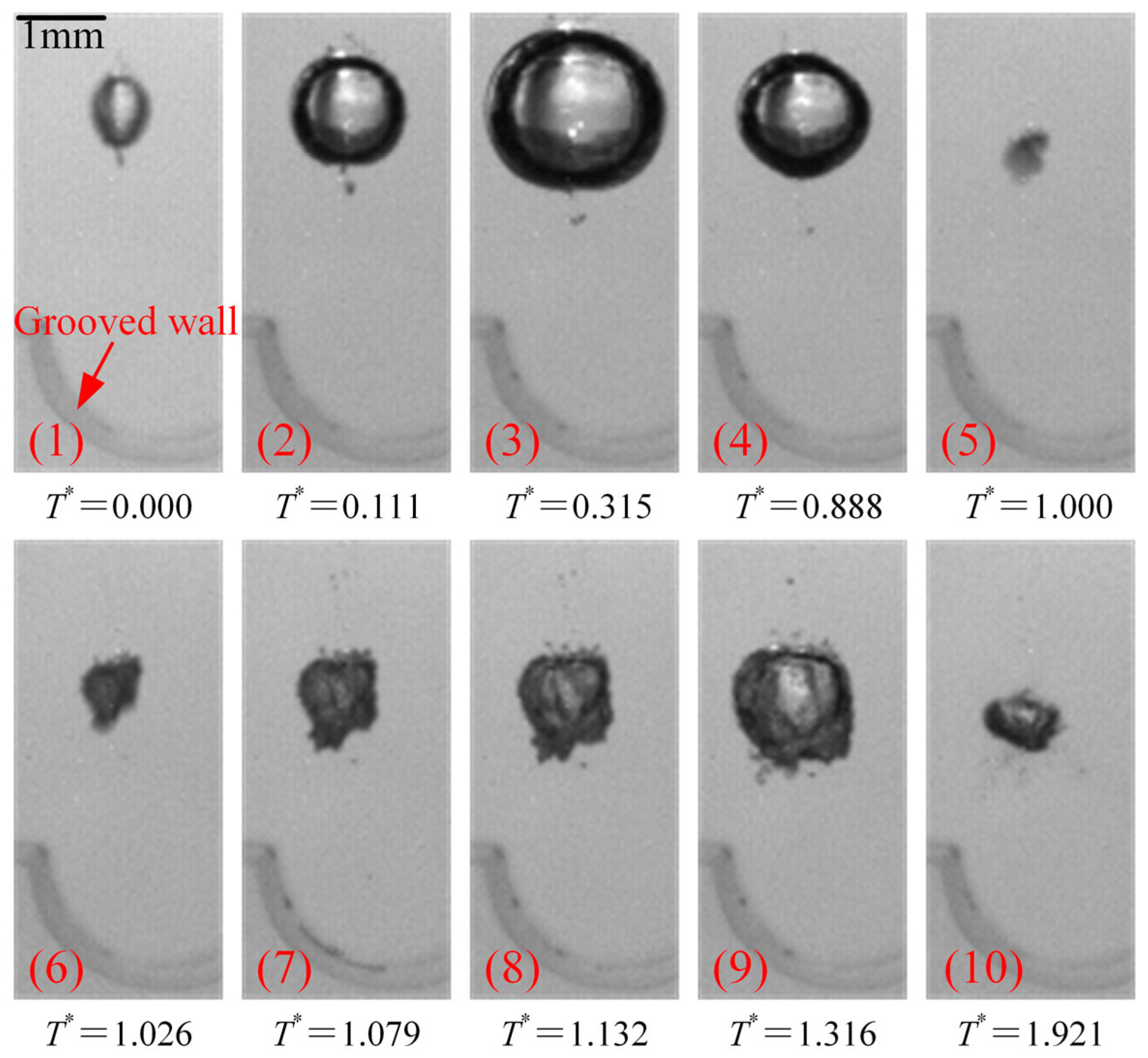
3. Cavitation Bubbles at Symmetric Positions
This section presents the high-speed photography results under different R* and l* and deeply analyzes the bubble collapse morphology and vortex ring evolution characteristics.
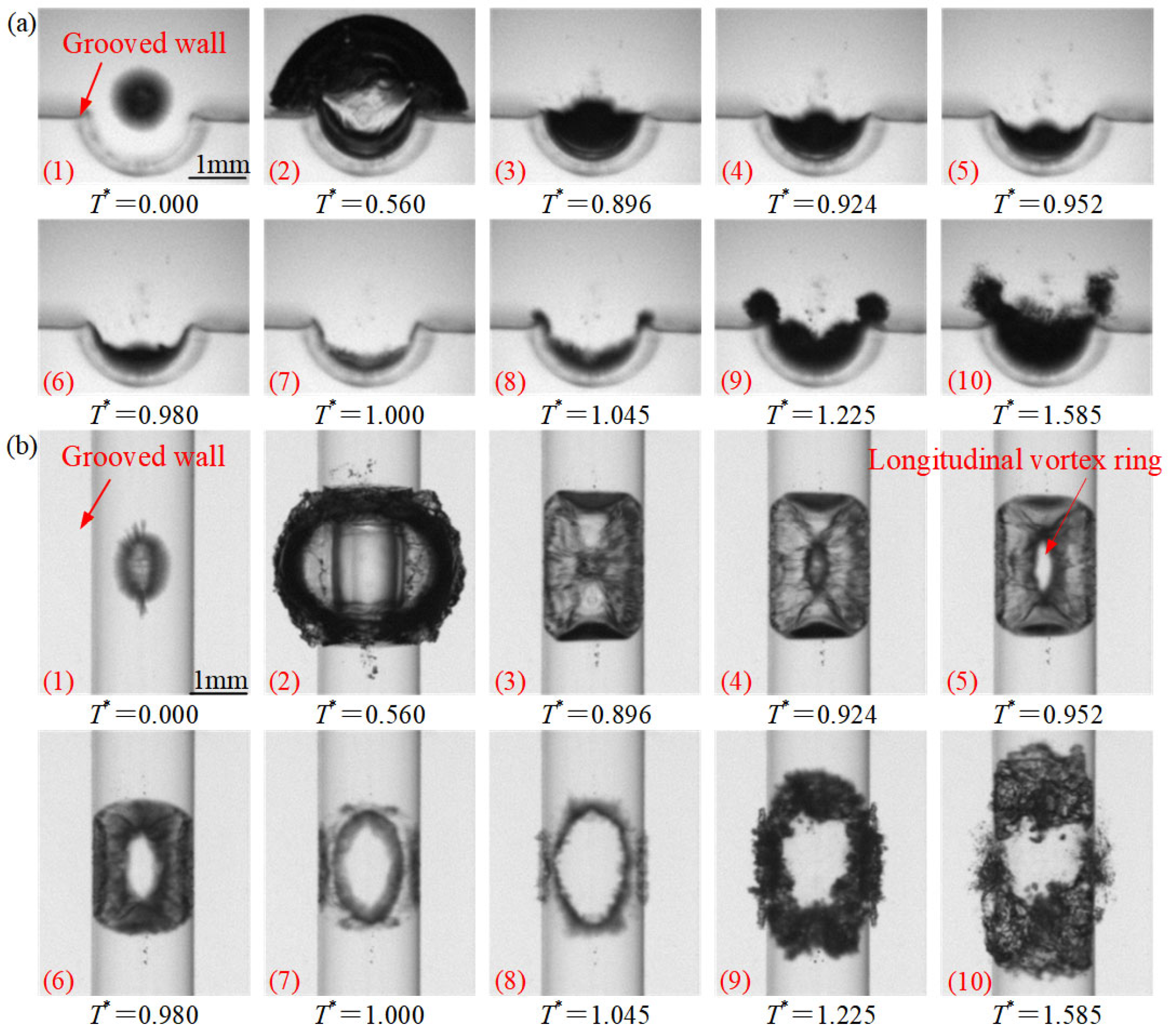
Figure 3 shows the evolution process of the bubble in the longitudinal elliptical vortex ring phenomenon from the front view (
Figure 3a) and top view (
Figure 3b;
R* = 1.8,
l* = 1.3,
θ = 0°). The scale is marked in the first frame, and the serial number and time are also marked in each frame. Frames 1~2 are the first period of the growth stage, and the lower part of the bubble wall is in contact with the wall. Frames 3~7 are the first period of the collapse stage, and a long elliptical vortex ring parallel to the groove channel is formed at the end of collapse. Frames 8~10 are the second period, and secondary cavitation bubbles are formed in the bubble cloud at the junction of the groove and the flat wall.
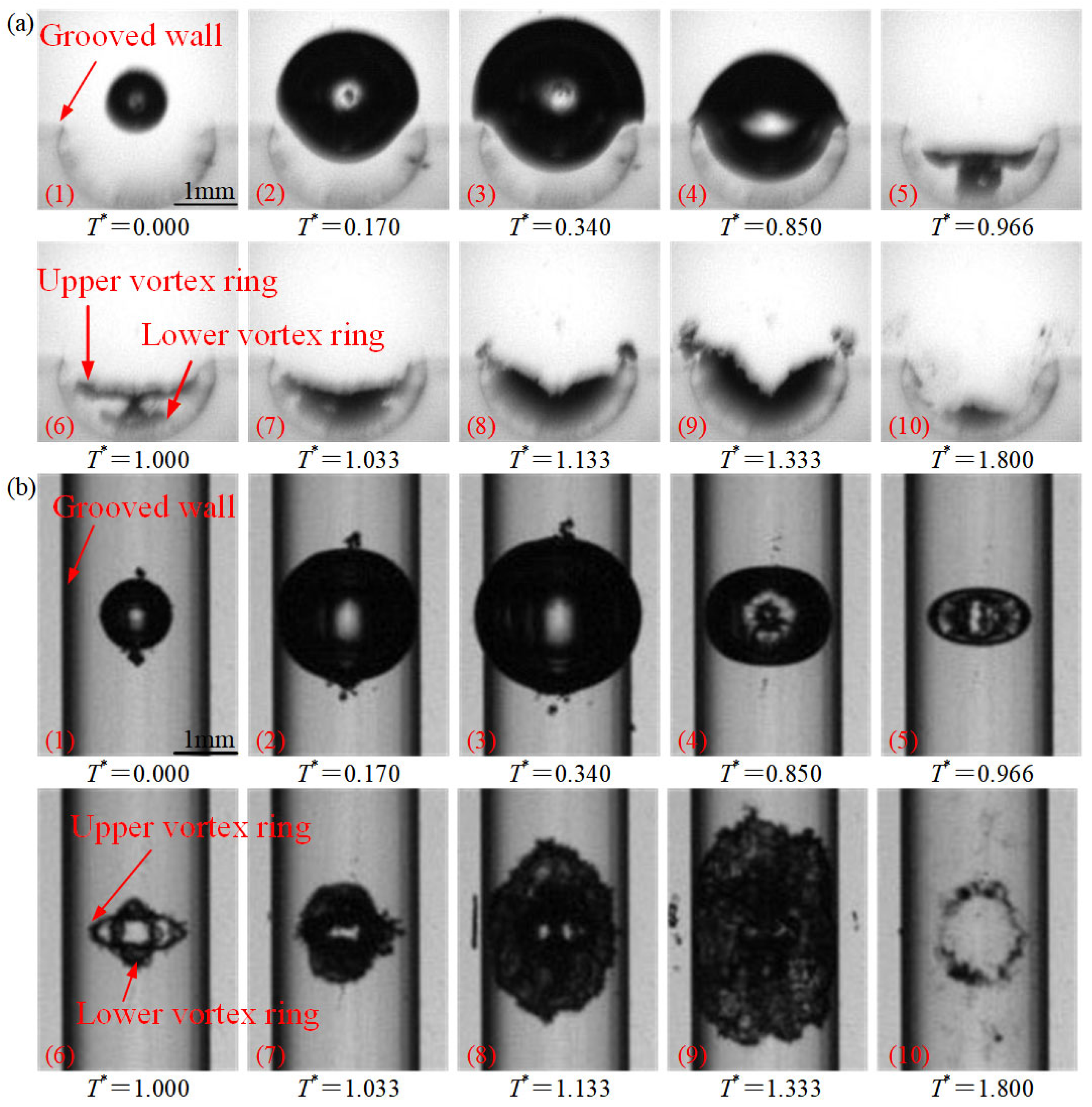
Figure 4 shows the evolution process of cavitation bubbles in the double-layer elliptical vortex ring phenomenon from the front view (
Figure 4a) and top view (
Figure 4b;
R* = 1.1,
l* = 1.4,
θ = 0°). Frames 1~3 are the first period of the growth stage, and the lower part of the bubble wall is in contact with the wall. Frames 4~6 are the first period of the collapse stage. At the end of the first collapse period, the cavitation bubble appears as two upper and lower bubbles in the front view, with the upper bubble larger than the lower one. In the top view, they are two overlapping elliptical vortex rings. The overall length of the vortex ring perpendicular to the groove wall is larger than that parallel to the groove wall. The larger bubble is the upper vortex ring, and the smaller bubble is the lower vortex ring.
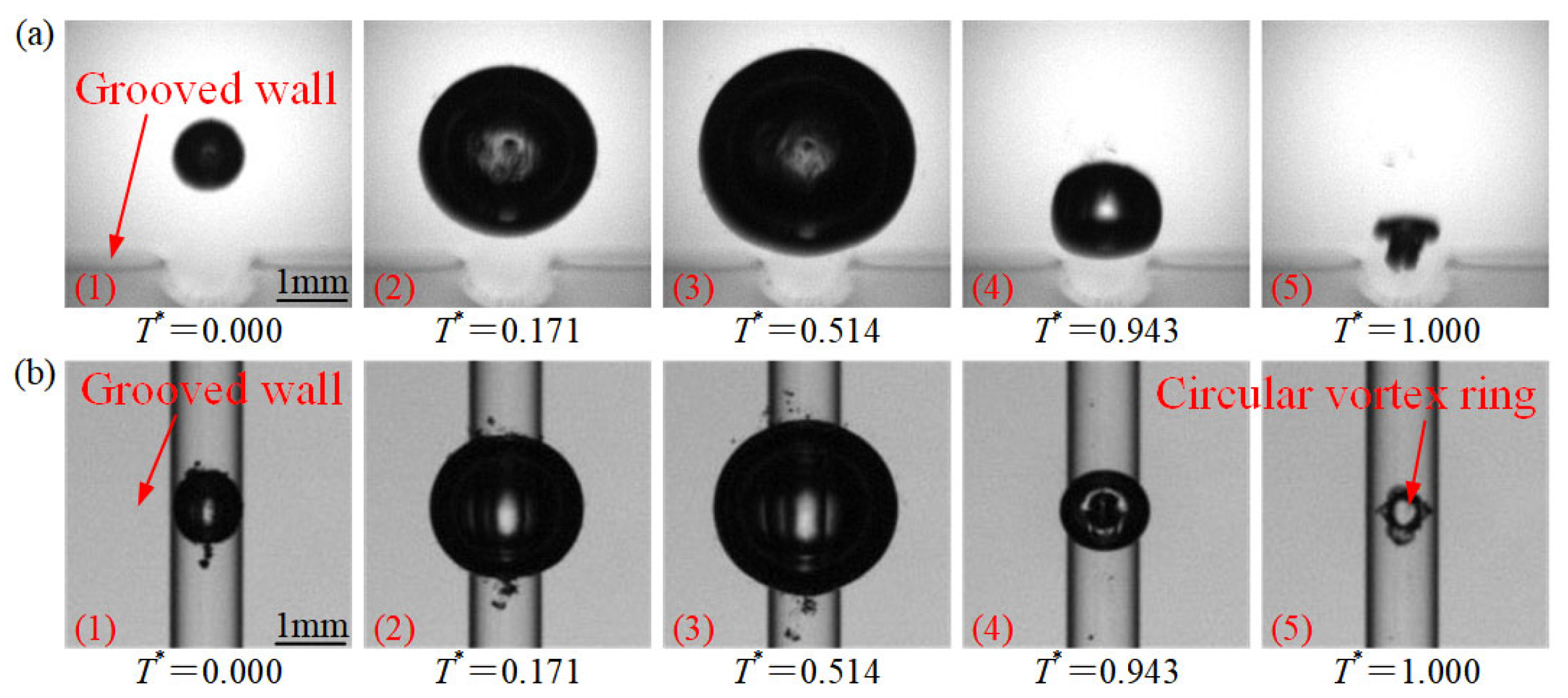
Figure 5 shows the evolution process of cavitation bubbles in the circular vortex ring phenomenon from the front view (
Figure 5a) and top view (
Figure 5b;
R* = 2.5,
l* = 2.1,
θ = 0°). Frames 1~3 are the first period of the growth stage, and the lower part of the bubble wall is not in contact with the wall. Frames 4 and 5 are the first period of the collapse stage. At the end of the first collapse period, the cavitation bubble is T-shaped in the front view, and a circular vortex ring is formed in the top view.
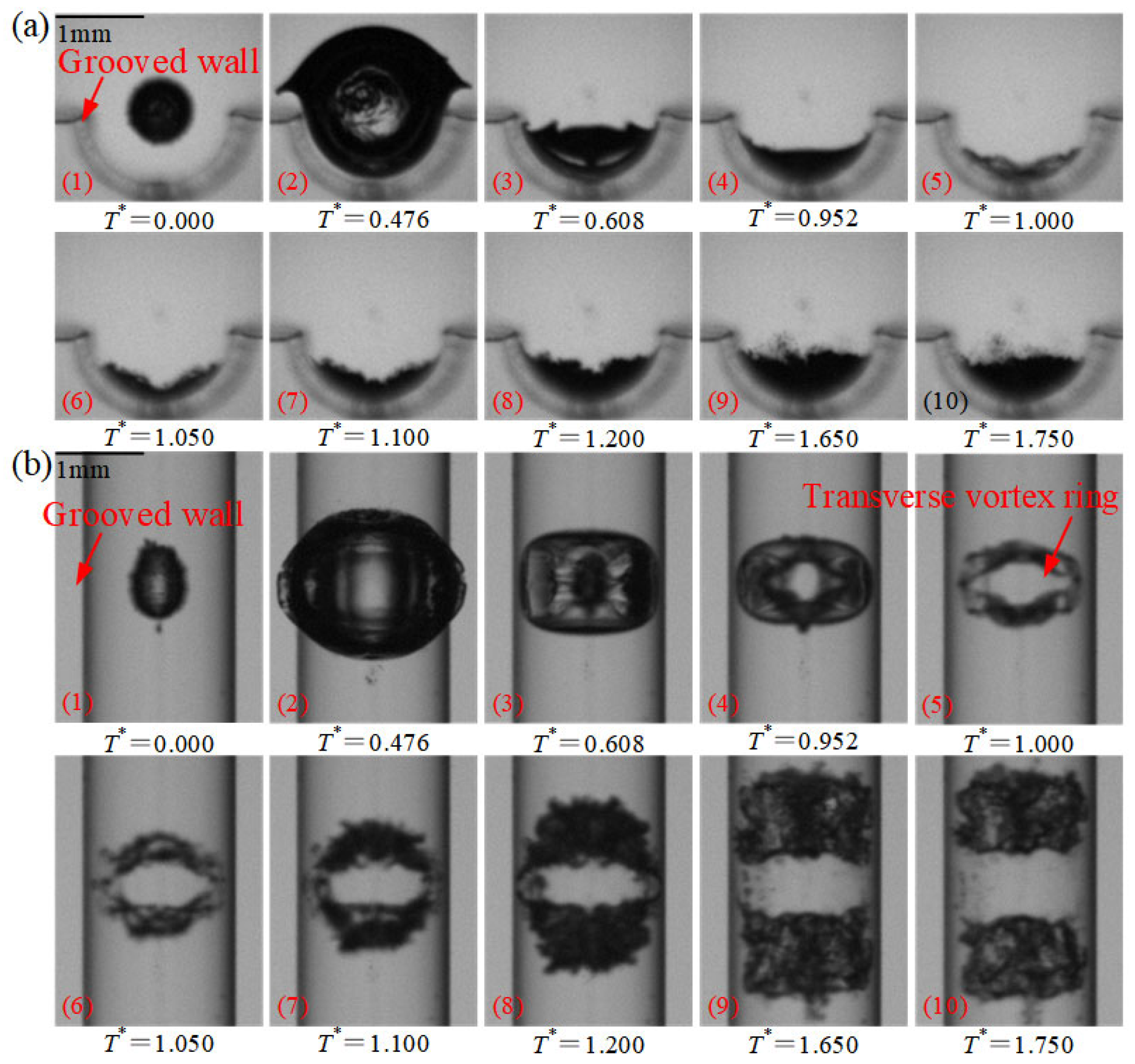
Figure 6 shows the evolution process of cavitation bubbles in the transverse elliptical vortex ring phenomenon from the front view (
Figure 6a) and top view (
Figure 6b;
R* = 1.2,
l* = 1.1,
θ = 0°). Frames 1~2 are the growth stage, and the lower part of the bubble wall is in contact with the wall. Frames 3~5 are the first period of the collapse stage, and a long elliptical vortex ring perpendicular to the groove channel is formed at the end of collapse. Frames 6~10 are the second period, and the vortex ring splits and moves away from each other along the groove channel.
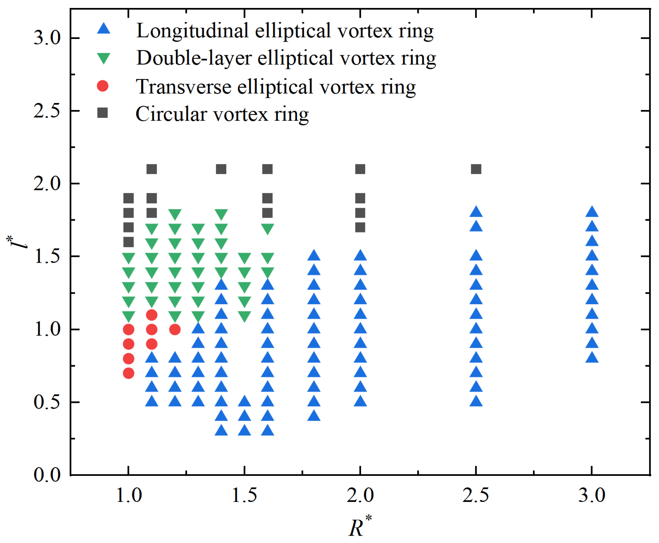
Figure 7 presents the partition map of vortex ring phenomena based on
R* and
l*. Different colored squares in the figure represent different vortex ring phenomena. The longitudinal elliptical vortex ring phenomenon occurs in the ranges of
R* = 1.1~3.0 and
l* = 0.3~1.8, the double-layer elliptical vortex ring phenomenon occurs in the ranges of
R* = 1.0~1.6 and
l* = 1.1~1.8, the transverse elliptical vortex ring phenomenon occurs in the ranges of
R* = 1.0~1.2 and
l* = 0.7~1.1, and the circular vortex ring phenomenon occurs in the ranges of
R* = 1.0~2.5 and
l* = 1.6~2.1. There are no transitional morphologies between these four vortex ring phenomena. It can be seen that the longitudinal elliptical vortex ring is the most frequent and occurs in the region with small
l*. Notably, as
R* increases, the corresponding
l* range for the longitudinal elliptical vortex ring phenomenon expands. The double-layer elliptical vortex ring phenomenon occurs in the region with medium
l*, and the circular vortex ring phenomenon occurs in the region with large
l*. When the initial centroid of the cavitation bubble is close to the center of the groove, a transverse elliptical vortex ring is often formed.
The physical mechanisms of the four typical vortex ring phenomena are briefly analyzed by integrating previous research findings. For the longitudinal elliptical vortex ring, the continuous curvature of the groove imposes an axial guiding effect on the underlying flow field when the bubble is close to the wall. The pressure difference across the bubble induces a jet along the groove axis (the direction of minimum resistance), which entrains ambient fluid to form an axially elongated vortex ring after penetrating the bubble [
10]. As
R* increases, the spatial range of the bubble influenced by the groove curvature expands, correspondingly widening the
l* interval for this vortex ring. For the double-layer elliptical vortex ring, at moderate
l*, the bubble is simultaneously affected by the grooved surface and adjacent flat walls. A primary jet forms along the groove axis, while the reflected flow at the groove mouth interacts with it to induce a secondary vortex ring below the primary one [
9]. This structure cannot form when
l* is too small (insufficient reflected flow intensity) or too large (weakened local groove effect). When
R* > 1.6, the large-scale bubble covers the entire groove and adjacent flat walls, smoothing out the local groove mouth effect. The axial guiding effect of the groove’s continuous curvature then dominates, leading to a transition to a single longitudinal elliptical vortex ring. For the circular vortex ring, when the bubble is sufficiently far from the groove, the local curvature disturbance to the global flow field is negligible, and the pressure field approximates that of an infinite flat wall [
21]. The jet then propagates vertically downward to the wall, forming an axisymmetric circular vortex ring after bubble penetration [
10,
11]. For the transverse elliptical vortex ring, when the bubble is very close to the groove center and has a small size, the transverse curvature constraint of the groove exceeds the axial constraint, making the direction perpendicular to the groove channel the path of minimum resistance. The collapse jet thus develops transversely and entrains fluid to form a transverse elliptical vortex ring. This phenomenon is unique to semi-cylindrical grooves due to their continuous curvature and only occurs near the groove center.