1. Introduction
In many applications related to the acoustic environment, the adaptive filtering algorithms represent the key signal processing tools [
1,
2,
3]. Among the most popular real-world examples, acoustic echo cancellation and noise reduction stand out as nowadays demands. In both scenarios, there is a need for modeling/estimating the acoustic impulse response associated to the inherent coupling between microphone and loudspeaker (especially in hands-free communication devices). This problem can be approached based on a system identification scheme [
4,
5], where an adaptive filter is used to model an unknown system impulse response, both being driven by the same input signal. In this framework, the challenge is basically twofold, i.e., (i) the long length of the acoustic impulse response and (ii) the time variability of the system to be identified. The first aspect implies using adaptive filters with hundreds/thousands of coefficients, which raises significant problems related to the computational complexity, while also affecting the main performance criteria (e.g., convergence rate and estimate accuracy). The second issue is related to the tracking capabilities of the adaptive filtering algorithm, which should cope with these inherent changes related to the acoustic environment (that can be influenced by many factors) [
1]. Besides, the input signal in acoustic applications is usually speech, which is characterized by high nonstationarity and strong correlation degree; both factors can challenge the overall behavior of the adaptive filtering algorithm.
Targeting a fast convergence rate, a good accuracy of the solution, and a robust behavior to correlated inputs (like speech), the recursive least-squares (RLS) [
2,
3] seems to be the algorithm of choice. Nevertheless, its performance gain is usually paid in terms of computational complexity. Moreover, the tracking capability of the conventional RLS algorithm is influenced by a specific parameter, namely the forgetting factor. This should be carefully tuned in order to achieve a proper compromise between some basic performance features, e.g., accuracy versus tracking. Motivated by these challenges, the current paper focuses on a “joint” approach, which exploits a decomposition-based technique combined with a solution using variable forgetting factors.
The recently developed decomposition-based adaptive filtering algorithms exploit the low-rank features of the impulse responses using the nearest Kronecker product (NKP) [
6,
7,
8]. As a result, a system identification problem with a large parameter space, which conventionally involves a single long-length adaptive filter, is reformulated by using a combination of shorter filters. The reduction in terms of parameter space results in a lower computational complexity, while using the combination of shorter adaptive filters improves the tracking capability of the decomposition-based algorithm. Consequently, these algorithms have been successfully applied lately, in the framework of various applications, e.g., see [
9,
10,
11,
12,
13,
14,
15,
16,
17,
18,
19,
20,
21] and the references therein. Most of these works rely on a second-order decomposition, where the impulse response to be identified is reshaped as a low-rank matrix [
22,
23], so that the resulting algorithm combines two adaptive filters. This is the most intuitive (and facile) way to handle this decomposition. Increasing the decomposition order could improve the overall performance, but the low-rank approach should be related in this case to higher-order tensors. On the other hand, handling the rank of a tensor is more challenging (as compared to the matrix case), usually involving additional approximation techniques [
24,
25,
26,
27,
28,
29,
30,
31,
32]. Alternatively, the methods proposed in [
33,
34,
35,
36] avoid this issue by controlling the tensor rank via a matrix rank. These approaches have been designed for the third-order tensor (TOT) and fourth-order tensor (FOT) decompositions, respectively.
The previous RLS-type solutions that rely on the second-order and third-order decompositions are usually referred as RLS-NKP [
7] and RLS-TOT [
34], respectively. They combine two, respectively three shorter adaptive filters, thus gaining in terms of the main performance criteria, as compared to the conventional RLS algorithm that involves a single (long-length) filter. Higher-order decompositions lead to shorter adaptive filters, with potential advantages in terms of both performance and complexity. On the other hand, lower-order decompositions provide simpler implementation schemes. Nevertheless, the overall performance can be improved for higher orders, as indicated in [
36].
Based on this motivation, we follow the recently introduced RLS algorithm based on a FOT decomposition, referred to as RLS-FOT [
36]. This algorithm combines four RLS-type adaptive filters, each one of them being controlled by an individual forgetting factor. Using constant values for these four specific parameters (which are positive and subunitary) leads to an inherent performance compromise. Larger values of the forgetting factors (i.e., closer to one) result in more accurate estimates, while paying with a slower tracking capability. Clearly, the tracking behavior can be improved by reducing the values of the forgetting factors, but sacrificing in terms of accuracy. This is an expected compromise, being valid for any exponentially-weighted RLS algorithm, which controls its overall performance using a constant forgetting factor [
2,
3]. In order to achieve a better balance between these performance criteria, the forgetting factors should be controlled in a time-dependent manner, targeting higher values in the steady-state (for a good accuracy) and lower values in tracking scenarios (for a fast recovery). While the problem formulation is straightforward, tuning these parameters in real-time applications could be challenging.
There are several RLS versions with variable forgetting factor (VFF), namely RLS-VFF, which are designed to address this challenge, e.g., see [
37,
38,
39,
40,
41,
42,
43,
44,
45,
46,
47,
48,
49] and the references therein. They are developed following the conventional form of the RLS algorithm, without the decomposition-based approach. Nevertheless, most of them require the tuning of extra parameters and/or additional control mechanisms with decision-based thresholds, which limit their practical applicability in real-world scenarios, like those related to the acoustic environment. Among these existing versions, the RLS-VFF algorithm recently proposed in [
49] stands out as one of the simplest, yet efficient, solutions. It is referred to as “nonparametric” in nature (i.e., parameter-tuning-free), which represents an appealing feature in practice.
In this paper, we propose a version of the RLS-FOT algorithm with variable forgetting factors, following the VFF-based idea from [
49], which was developed for the basic RLS algorithm. The extension to the fourth-order decomposition-based version is not straightforward, due to the specific connection between the four component filters (with different lengths), which operate in parallel. In this context, it should be outlined that the RLS-FOT algorithm owns intrinsic symmetry features. Following this introduction,
Section 2 presents a basic form of the RLS-FOT algorithm. This is further exploited in
Section 3, for developing the proposed version with variable parameters. The experimental framework from
Section 4 considers an echo cancellation scenario, and the obtained results support the performance gain of the resulting algorithm. Finally, several conclusions and perspectives are summarized in
Section 5.
2. Basic RLS-FOT Algorithm
Let us consider a time-varying impulse response of length
(with
), having its coefficients grouped into the vector
, where
t is the discrete time-index. As shown in [
6], due to its low-rank properties, such an impulse response can be expressed as
with
, where the shorter impulse responses
and
have the lengths
and
, respectively, being combined via the Kronecker product [
50], denoted by ⊗. For an exact representation, the sum from (
1) should have
terms, instead of
R. In fact, this representation is associated to the (approximated) rank of the matrix
, of size
, which results by reshaping the impulse response
. In real-world applications and especially in echo cancellation scenarios [
8], the matrix
is never full rank, so that we can use
R as its (approximated) rank. Usually, in AEC scenarios, the common setup is
, while for sparser impulse responses (e.g., like in network echo cancellation), the frequent choice is
[
6,
7]. Furthermore, as indicated in [
35,
36], this nearest Kronecker product (NKP) representation can be further applied to the component impulse responses from (
1), which can also be considered as low-rank systems. As a result, using the factorizations
(with
) and
(with
), the global impulse response becomes
with
and
, where the impulse responses
,
,
, and
have the lengths
,
,
, and
, respectively. In other words, for
, reshaping
as an
matrix,
, while
is reshaped in the form of an
matrix,
, these also represent low-rank structures, with the approximated ranks
and
, respectively. As shown in [
35,
36], the common settings for these parameters are
and
. This fourth-order decomposition could also be interpreted as a “double-level” NKP approach.
The recently developed RLS-FOT algorithm [
36] exploits this fourth-order decomposition and expresses its estimate in a similar manner, i.e.,
where
denotes an estimate of
, while
,
,
, and
represent the estimates of
,
,
, and
, respectively (considering the same associated lengths). Clearly, there is a scaling ambiguity when identifying the component impulse responses, since
, with
and
. Nevertheless, the main goal is to estimate
via
, which is obtained without any scaling ambiguity.
In [
36], the RLS-FOT algorithm has been designed following the line of the conventional RLS filter using the matrix inversion lemma [
2,
3]. To the purpose of simplifying the upcoming development from
Section 3, we develop here a basic version of the RLS-FOT algorithm. First, let us introduce the conventional least-squares (LS) optimization criterion [
2,
3], which relies on the cost function:
where
is known as the forgetting factor,
denotes the samples of the reference (or desired signal), with
, while
represents the input signal vector (of length
L) for the corresponding moment of time, which groups the last
L samples of the input sequence; here, the superscript
⊤ stands for transposition. Since the RLS-FOT algorithm focuses on the component filters, it considers four cost functions (i.e., one for each specific group of coefficients), with individual forgetting factors, denoted in the following by
, with
. In other words, following a multilinear optimization strategy [
51], which considers that three of the systems are fixed (for all the previous time-indices, i.e.,
) during the optimization of the remaining fourth one (at time index
t), the associated cost functions result in
where
,
,
, and
group the coefficients of
,
,
, and
, respectively, with
,
, and
, as indicated in
Table 1. Also, the “inputs”
, with
and
, combine the samples of
with the remaining sets of coefficients, as indicated in
Table 2 (for the time index
t). These two tables contain the specific notation related to the fourth-order decomposition and the RLS-FOT algorithm [
35,
36]. Basically, the properties of the Kronecker product are exploited, which allow the equivalent representations of (
3), i.e.,
with the purpose of separating and extracting the individual components; here, the general notation
represents the identity matrix of size
, with
. In this context, the a priori error signal of the adaptive filter, which is defined as
, can be equivalently expressed in four alternative ways, i.e.,
with
, using the same notation from
Table 1 and
Table 2. Clearly,
; however, for the sake of clarity of the upcoming developments and the facile association with the component filters, the notation from (
10) will be used in the following.
At this point, the minimization of the cost functions from (
5)–(
8) with respect to the corresponding components, i.e.,
, with
, under the multilinear optimization framework [
51], lead to the associated sets of normal equations:
respectively, where
using the general notation. While for developing the solutions of (
11) the RLS-FOT algorithm from [
36] exploits the matrix inversion lemma [
2,
3], here we present a basic form of this algorithm. To this purpose, let us consider the normal equations (
11) from time index
, i.e.,
with
. Next, (
14) can be multiplied by
on both sides, while using the recursions (
12) and (
13), so that it results in
Developing (
15) and using the a priori errors from (
10), we obtain
Finally, assuming that
is invertible, so that
, and multiplying (
16) to the left by
, the updates of the component filters result in
Summarizing, the basic form of the RLS-FOT algorithm is defined by the relations (
10), (
12), and (
17), with
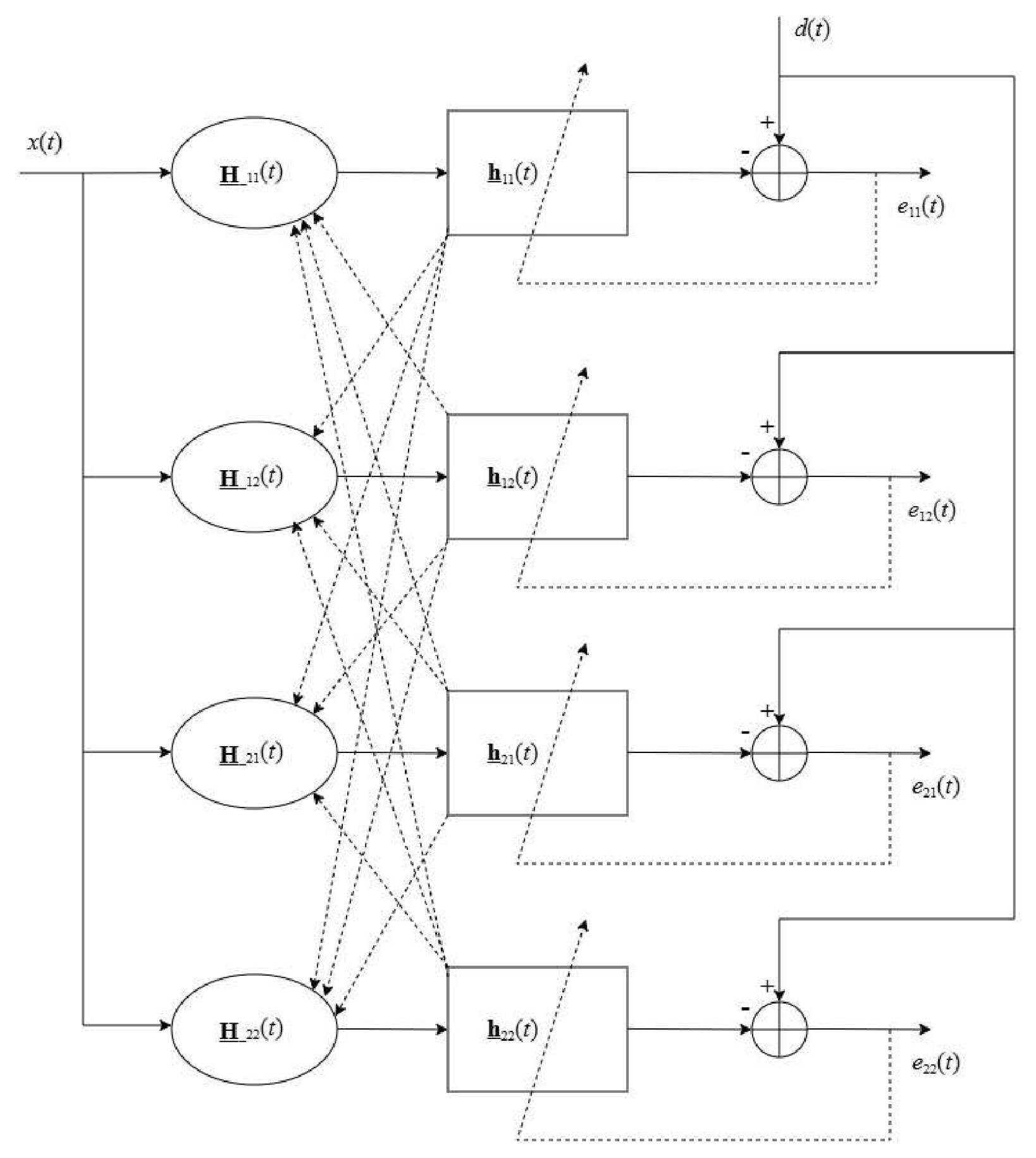
. These four component filters are interconnected (via their coefficients) and operate in parallel, as indicated in
Figure 1. It can be noticed that the structure of the algorithm is characterized by intrinsic symmetry features.
The parameter space of the conventional RLS algorithm comprises
L coefficients, which could be problematic for long-length adaptive filters, like in acoustic applications. On the other hand, the RLS-FOT combines four shorter adaptive filters, with a total parameter space of
coefficients (see
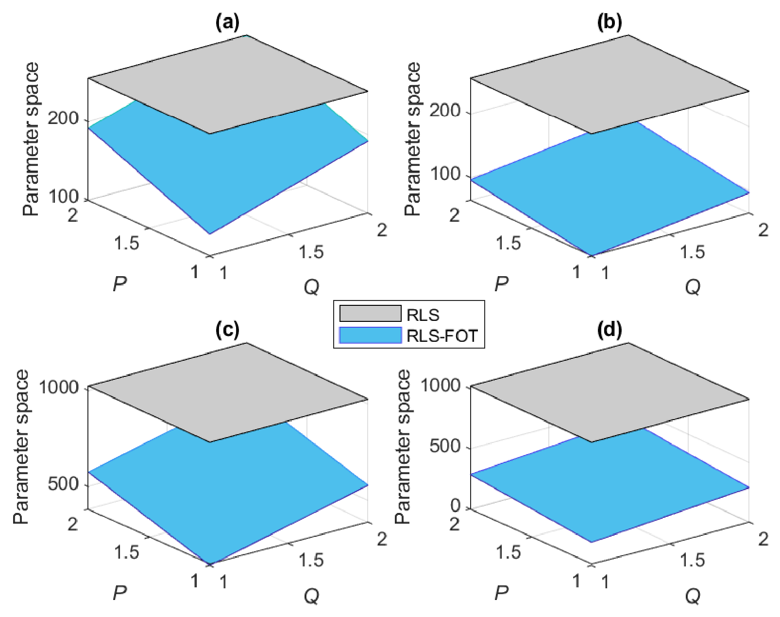
Table 1). For the common decomposition setup, there is a significant reduction in the case of the RLS-FOT algorithm, as compared to the conventional approach that considers a single long-length adaptive filter. This is supported in
Figure 2, where two examples are examined (for different scenarios), with
and
. In the first case, the factorization is performed using
, while the second scenario is handled using
,
,
, and
. As explained in the beginning of this section and also indicated in [
36], the common setup for
R is in the range
to
, while the values of
P and
Q are usually smaller than
and
, respectively. Under these circumstances, the parameter space (i.e., the number of coefficients) of the RLS-FOT algorithm is significantly lower than the conventional RLS counterpart, which is represented by the gray surface in
Figure 2a–d. Since the computational complexities of these algorithms directly depend on the corresponding number of coefficients, the gain is important in the case of RLS-FOT version, as also supported in [
36].
3. RLS-FOT Algorithm with Variable Forgetting Factors
The main control parameters of the RLS-FOT algorithm are the four forgetting factors, i.e., , , , and , which correspond to the component filters , , , and , respectively. The parameters have positive subunitary values, which should be tuned to achieve a proper balance between the tracking capability and the estimate accuracy. Using constant values for the forgetting factors leads to an inherent (yet expected) compromise between these performance criteria. Ideally, large values (i.e., close to one) should be used to obtain a good accuracy of the filter estimate, while smaller values of the forgetting factors improve the tracking behavior. This conflicting requirement can be addressed by using variable forgetting factors (VFFs), which should be designed as time-dependent parameters, i.e., , , , and . Nevertheless, for practical reasons, the resulting VFFs should be facile to evaluate in real-world/real-time applications, without requiring additional control mechanisms.
To this purpose, we follow the recent idea from [
49], which was designed in the framework of the conventional RLS algorithm. First, let us define the a posteriori errors of the RLS-FOT algorithm, which are evaluated similar to (
10), but using the updated filters’ coefficients from time index
t, i.e.,
with
. Since the “input” sequences,
, depend on the filters’ coefficients from the previous time index
(see
Table 2), the a posteriori errors from (
18) are not equal anymore, contrary to the a priori errors from (
10). Using the filters’ updates (
17) in (
18), also considering the a priori errors (
10), the relations between these two types of errors result in
According to (
12), the matrix
, with
, represents an estimate of the covariance matrix of the input sequence
. Therefore, based on (
12) and considering that
t is large enough, we can use the reasonable approximation:
where
denotes the mathematical expectation and the deterministic time-dependent forgetting factors,
’s, are considered. Also, since the lengths of the corresponding filters are usually much greater than one, the variance of the input sequence
, denoted by
(with
), can be fairly approximated as the ratio between the product
and the corresponding filter length. Under these circumstances, the expressions from (
19) become
The conventional RLS algorithm results following the LS optimization criterion based on the cost function from (
4) [
2,
3]. It operates on a single filter of length
L, using the forgetting factor
. This control parameter of the RLS filter is usually evaluated as
with
set as an integer value. The main reason is that
is a memory-related parameter, which should be associated to the filter length [
2,
3]. Alternatively, for a better flexibility/control related to the dynamic range of the variables, the forgetting factor can be evaluated as
, where
is now limited between 0 and 1. Thus, instead of directly finding a variable forgetting factor,
, the main focus is redirected on designing a time-dependent parameter,
. This was the strategy behind the development of the RLS-VFF algorithm from [
49]. In the case of RLS-FOT algorithm, the time-dependent forgetting factors should be related to the corresponding filters’ lengths, such that
where
, with
. Using (
26)–(
29) in (
21)–(
24), we obtain
At this point, the most problematic terms are the covariance matrices from the right-hand side of (
30). An accurate evaluation of these terms represents a difficult task, since the “input” sequences
, with
, depend on the filters’ coefficients from time index
, as shown in
Table 2 and also indicated in
Figure 1. Nevertheless, it can be considered that these covariance matrices are still dominated by their main diagonal, so that
, where
denotes the identity matrix of appropriate size. Clearly, this is a strong assumption, which is especially valid when
is white and Gaussian, while the filters’ coefficients are nearly statistically independent. The assumption on the character of the input signal could look quite restrictive, especially in audio applications. However, the motivation behind it is twofold. First, it is used only for deriving the VFFs, while the (full) matrices
, with
, are still used within the filters’ updates (
17). Second, it greatly facilitates the upcoming developments related to the VFFs, since the relations from (
30) simplify to
Based on (
31), the parameters
, with
can be obtained by following a natural condition in system identification problems. Let us consider that the reference/desired signal,
, is obtained at the output of a system characterized by the impulse response
from (
1), corrupted by a zero-mean additive noise,
, which is uncorrelated to the input signal. Therefore,
where
is the same input sequence that drives the adaptive filter, like in a system identification scenario [
2,
3]. In this framework, when the adaptive filter converges to its steady-state, so that
, the noise signal should be recovered from the error signal [
49,
52]. Hence, in the context of RLS-FOT algorithm, the conditions to follow are
with
, where
is the variance of
. Next, squaring and taking the expectations in (
31), the set of conditions from (
33) leads to the equations:
where
. Considering that
’s are deterministic (with
) and solving the quadratic Equation (
34), the valid solutions result in
so that the VFFs from (
26)–(
29) become
The variances from (
36)–(
39) can be recursively estimated, using different smoothing factors, i.e.,
where
and
, with
(e.g., on the order of tens). Clearly, different other methods can be used for estimating the noise power; however, the estimation from (
41) represents one of the simplest solutions, since it also relies on the error signal, which is already available. As explained after (
10), the four a priori errors,
, with
, are equal to
, while the distinct notation is kept for the sake of clarity and the proper association to the corresponding component filters. Thus, the parameters
from (
35) are also equal, so that the differences between the four VFFs from (
36)–(
39) are due to the corresponding filters’ lengths. Since the VFFs involve the estimation of
, which is associated to the external additive noise, a challenging situation could appear when
is nonstationary, as in the double-talk case [
1]. In such a scenario, two approaches can be considered: (i) a double-talk detector to control the algorithm behavior during that period and (ii) a more rigorous estimation of
, which will be subject for future works. While the estimation from (
41) is one of the simplest and most practical solutions, it might not cope with the double-talk scenario, where the nonstationary nature of the near-end speech could significantly bias the adaptive filter behavior. In this context, a regularized version of the algorithm could also be considered in perspective, by incorporating proper regularization terms within the cost functions from (
5)–(
8), aiming to improve the overall robustness against different external perturbations.
The resulting RLS-FOT algorithm with VFFs has been formulated following the basic form of the algorithm from
Section 2, which facilitated the previous development. Nevertheless, the designed VFFs can be incorporated within the RLS-FOT version from [
36], which uses the matrix inversion lemma to avoid the direct evaluation of
from (
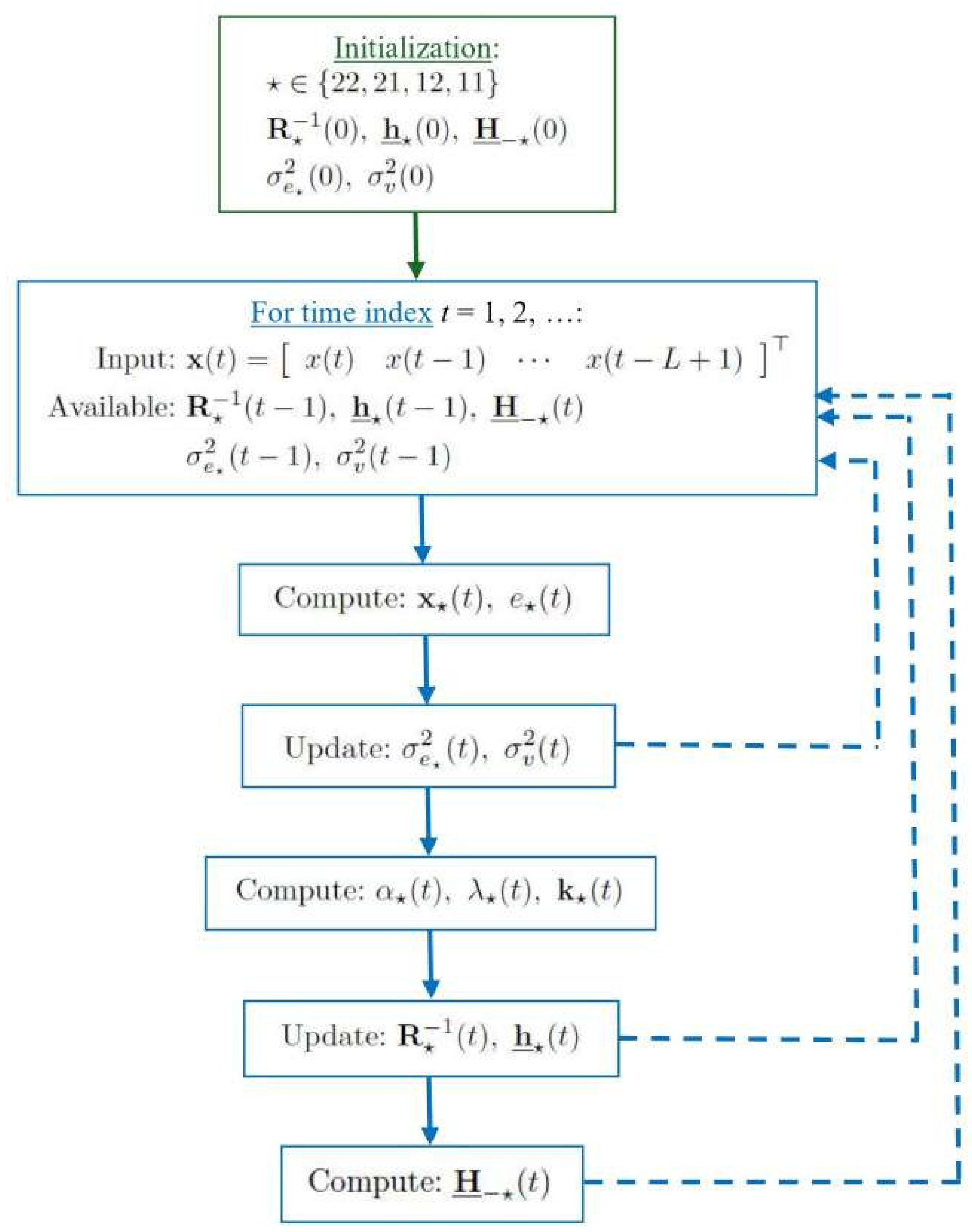
17). In this context, the proposed algorithm (referred as RLS-FOT-VFFs) is summarized in
Table 3. Here, the notation
and
indicate the identity matrix and an all-zeros column vector, respectively, with the corresponding size/length indicated in subscript. In addition, a flowchart of the algorithm is depicted in
Figure 3.
The initialization for
, with
, requires the positive constant
on the main diagonal, in order to prevent potential numerical issues. This is a standard initialization of the RLS-type algorithms, which represents the simplest and most practical solution. Other more rigorous initialization procedures could be considered, as indicated in [
53]. Nevertheless, due to the presence of the subunitary forgetting factors,
, the contribution of the initialization of
is quickly attenuated through the iterations and has basically no influence in the steady-state of the algorithm. Usually, the all-zeros initialization is used for the coefficients of the adaptive filter. However, due to the combination that involves the Kronecker products (see also
Table 2), the all-zeros initialization would stall the RLS-FOT-VFFs algorithm. Consequently, the small positive constant
is used to prevent this issue, as shown in
Table 3. Finally, a very small positive constant,
, is added to the denominator of
, with
, in order to avoid divisions by zero.
Due to the use of the matrix inversion lemma to update the matrices
, with
, the notation for the Kalman gain vectors [
2,
3] is used in
Table 3, i.e.,
. This allows a more compact expression for the update of
, but also for the coefficients’ update,
. Clearly, the filters’ updates from (
17) are equivalent to the updates of
from
Table 3, since
.
The computational complexity of the proposed RLS-FOT-VFFs algorithm is on the same order with its RLS-FOT counterpart from [
36]. The specific operations of the RLS-FOT-VFFs algorithm are related to the evaluation of its time-dependent forgetting factors, i.e., the computation of
,
,
, and
, with
. These require only a few extra operations, with a total amount of
multiplications,
additions,
divisions, and
square-roots operations, for all the four component filters. As indicated in [
36], the complexity order of the RLS-FOT algorithm is
, so that the extra computational amount required by the VFFs’ evaluation is negligible and does not depend on the filters’ lengths.
A detailed evaluation of the computational complexities (in terms of the number of multiplications and additions per iteration) of the main comparing algorithms is included in
Table 4. Here, the computational amounts that mainly involve Kronecker product operations and lead to
(see
Table 2) are denoted by
and
, respectively. Generally, these amounts are on the order of
, even if the specific operations related to the Kronecker product can be further optimized [
54,
55]. As a numerical example, let us consider the length
, which is factorized using
,
,
, and
. In this case, the conventional RLS algorithm and the RLS-VFF version from [
49] require around
multiplications and
additions (per iteration). On the other hand, the decomposition-based algorithms, i.e., RLS-FOT [
36] and RLS-FOT-VFFs (both using
,
, and
) need around
multiplications and
additions (per iteration). Here, the decomposition parameters
R,
P, and
Q have been set to their maximum recommended values (as explained in the beginning of
Section 2), so that the resulting computational amount represents an upper bound. Using smaller values for these parameters (as also supported in the next section), significantly reduce the computational complexity of the decomposition-based algorithms.
4. Simulation Results
The performances of the proposed RLS-FOT-VFFs algorithm are assessed in the framework of echo cancellation [
1,
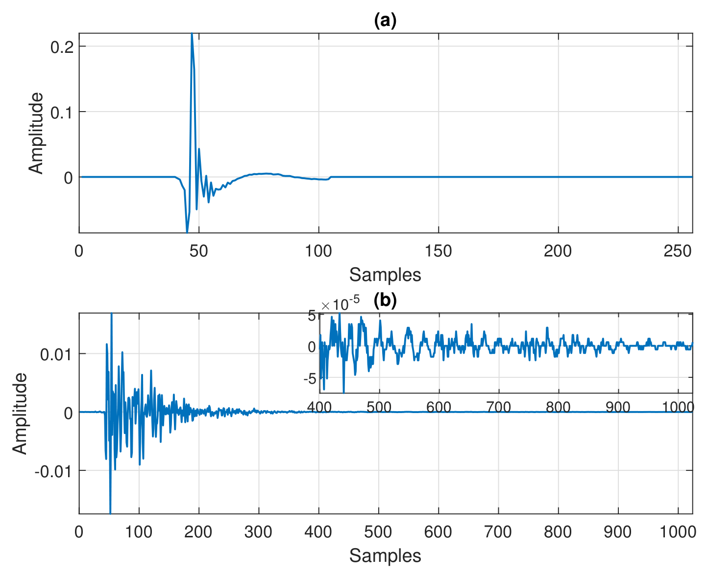
56]. Two impulse responses are considered in the experiments, as shown in
Figure 4a,b, with the lengths
and
, respectively; the sampling rate is 8 kHz. The first one is a network impulse response from ITU-T G168 Recommendation [
56], which is obtained using the first cluster of coefficients padded with zeros up to the length
. The second one is a measured acoustic impulse response of length
. The factorization of
is performed using
, while
is factorized with
,
,
, and
, respectively. Different other factorization strategies can be used, as discussed in [
36]. However, the main goal of the current experiments is to support the performance features of the VFFs-based approach. These impulse responses are selected to illustrate the behavior for both sparse and dispersive systems, which can be associated to network and acoustic echo cancellation, respectively. Their different lengths allow a twofold evaluation, i.e., (i) related to the FOT factorization and (ii) related to the influence of the length of the adaptive filter.
The input sequence is a noisy speech obtained from different recorded female voices available in the Open Speech Repository [
57], which are selected among the first 10 files from the “American English” category. Nevertheless, the performances of the algorithms are very similar when using different speech sequences. The input signal represents the voice of the far-end speaker,
, which propagates through the echo path,
, thus resulting the echo signal. Further, the echo signal is corrupted by a background noise,
, thus obtaining the reference/desired signal,
, from (
32). In this context, the signal-to-noise ratio (SNR) is defined as the ratio between the variance of the echo signal and
. Its value is set to 20 dB in most of the experiments, which represents a realistic communication scenario, with moderate SNR. Also, in some simulations, a noisy environment is considered, using
dB. The tracking capabilities of the adaptive filter are assessed in each experiment, by abruptly changing the echo path, introducing a right-shift of its impulse response by 8 samples.
Since echo cancellation basically represents a system identification problem, where the adaptive filter,
, is used to model/estimate the impulse response of the echo path,
, a standard performance measure is the normalized misalignment (or system mismatch) [
1]. This is defined (in dB) as
, where
denotes the Euclidean norm. Clearly, a lower misalignment indicates a better accuracy of the algorithm. Also, a steeper misalignment curve indicates a better convergence rate and/or tracking capability of the adaptive filter.
In order to establish the benchmarks used in comparisons, a preliminary set of experiments evaluates the performances of several standard algorithms, as compared to the recently developed RLS-VFF version from [
49], for the identification of the impulse response from
Figure 4a. In terms of computational complexity and facility of implementation, the normalized least-mean-square (NLMS) algorithm is usually considered the workhorse in adaptive filtering [
2,
3], with a computational complexity proportional to
. Its main control parameter is the normalized step-size,
, which is a positive constant smaller than 2 (for stability), with the fastest convergence mode obtained for
. On the other hand, a fast convergence rate is paid by a reduced accuracy of the filter estimate (i.e., larger misalignment). Besides, the NLMS algorithm is sensitive to the character of the input data, especially in terms of the correlation degree. To overcome this shortcoming, the affine projection algorithm (APA) [
58] represents an appealing alternative, with better convergence properties for correlated inputs and a moderate increase of the computational complexity, as compared to the NLMS algorithm. Besides the step-size parameter, the performance of APA is influenced by the projection order,
M, which is a positive integer larger than or equal to one. In fact, for
, the APA is equivalent to the NLMS algorithm. When the value of
M increases, the convergence rate of APA is improved, especially for correlated inputs. The computational complexity of APA is proportional to
, so that it is proportional to the filter length. On the other hand, the standard RLS algorithm requires a computational amount proportional to
, while owning improved convergence properties as compared to APA, even for correlated inputs. Its performance is controlled by the forgetting factor, which is usually set based on (
25).
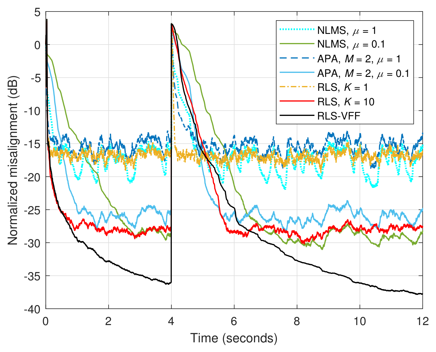
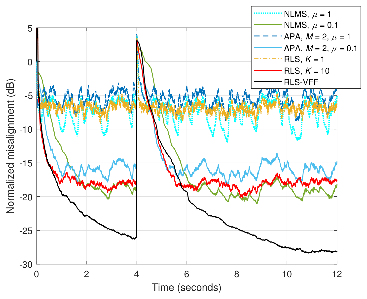
The performances of these standard algorithms are shown in
Figure 5 and
Figure 6, for
dB and 10 dB, respectively. Different values of the specific convergence parameters are set for the standard algorithms, outlining their influence on the overall behavior. As explained before,
leads to the fastest convergence/tracking of NLMS/APA, but with a high misalignment level. On the other hand, a smaller value of
improves the accuracy (i.e., lower misalignment), but pays with a slower convergence/tracking. The influence of the projection order of APA is also revealed in
Figure 5 and
Figure 6, improving the convergence rate and tracking of the NLMS algorithm, while reaching a higher misalignment level. The RLS algorithm obtains the fastest initial convergence rate, but its tracking capability is highly influenced by the value of the forgetting factor. For example, a larger value of
(or
K) leads to a better accuracy of the filter estimate (i.e., lower misalignment), while paying with a slower tracking reaction. In this context, the RLS-VFF algorithm from [
49] outperforms its standard counterparts, achieving a better balance between the main performance criteria, with fast convergence/tracking and low misalignment. The same conclusions are valid for different SNR levels.
As a result, the selection of the comparing algorithms is made based on the following considerations. First, as indicated in [
36], the RLS-FOT algorithm can outperform other previously developed decomposition-based counterparts [
7,
34], so that it is considered as a comparison benchmark. It uses the same decomposition setup as the proposed VFFs-based algorithm, while its forgetting factors are set as constant values, following the rule-of-thumb mentioned in
Section 3. Hence, the settings are
with
and
, while
generally denotes the length of the corresponding component filter, i.e.,
,
,
, and
, respectively. Second, supported by the previous set of experiments, the RLS-VFF algorithm from [
49] is considered in comparisons, which relies on a similar idea for developing its time-dependent forgetting factor. In this case, its VFF is evaluated as
with
, where the variances are evaluated similar to (
40) and (
41). As indicated in [
49], this algorithm outperforms the conventional RLS benchmark (see also
Figure 5 and
Figure 6) and other VFF-based RLS-type algorithms. Nevertheless, it involves a single (long-length) adaptive filter, with
L coefficients, which inherently influences its performance features. On the other hand, the proposed RLS-FOT-VFFs algorithm combines the estimates provided by four (much) shorter adaptive filters, with expected gains in terms of tracking and accuracy.
In the first set of experiments, the identification of the sparser impulse response (
) from
Figure 4a is evaluated.
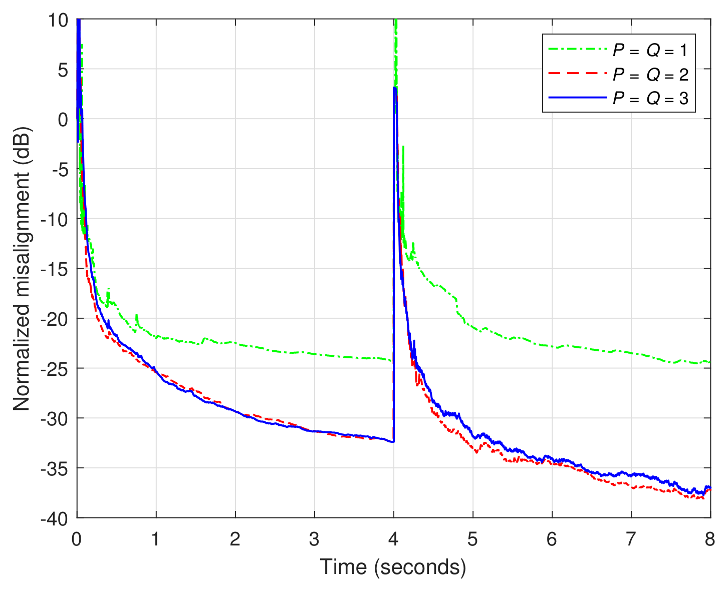
Figure 7 shows the results obtained by the RLS-FOT-VFFs algorithm for different values of
, using
and
in (
41). It can be noticed that even for
, the proposed algorithm obtains a misalignment level around
dB, which represents a good balance between performance and complexity. As expected, the performance is improved for
, these values being equivalent to
and
, respectively. Increasing the values of
P and
Q beyond these limits is not justified in terms of performance improvement, as also noticed in
Figure 7.
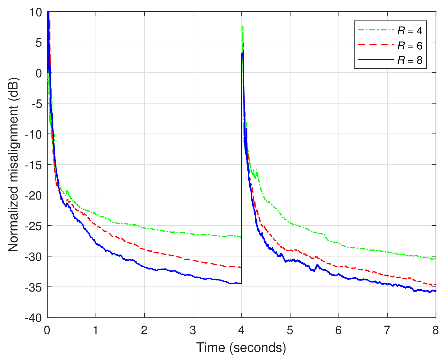
Next, the influence of the decomposition parameter
R is investigated in
Figure 8. This parameter is related to the first “level” of the NKP decomposition, according to (
1). Usually, as also indicated in previous works [
36], this value does not exceed
for low-rank impulse responses. In this context, the values considered in
Figure 8 are
,
, and
. Clearly, the performance is improved (i.e., lower misalignment) for larger values of
R, while there is an inherent saturation at some point. Taking into account that the computational complexity also increases with the value of
R, the practical limit
could be considered as a recommended choice.
The only parameter that has to be set within the RLS-FOT-VFFs algorithm from
Table 3 is related to the smoothing factor used within the estimation of
from (
41). As indicated in
Section 3, the value of
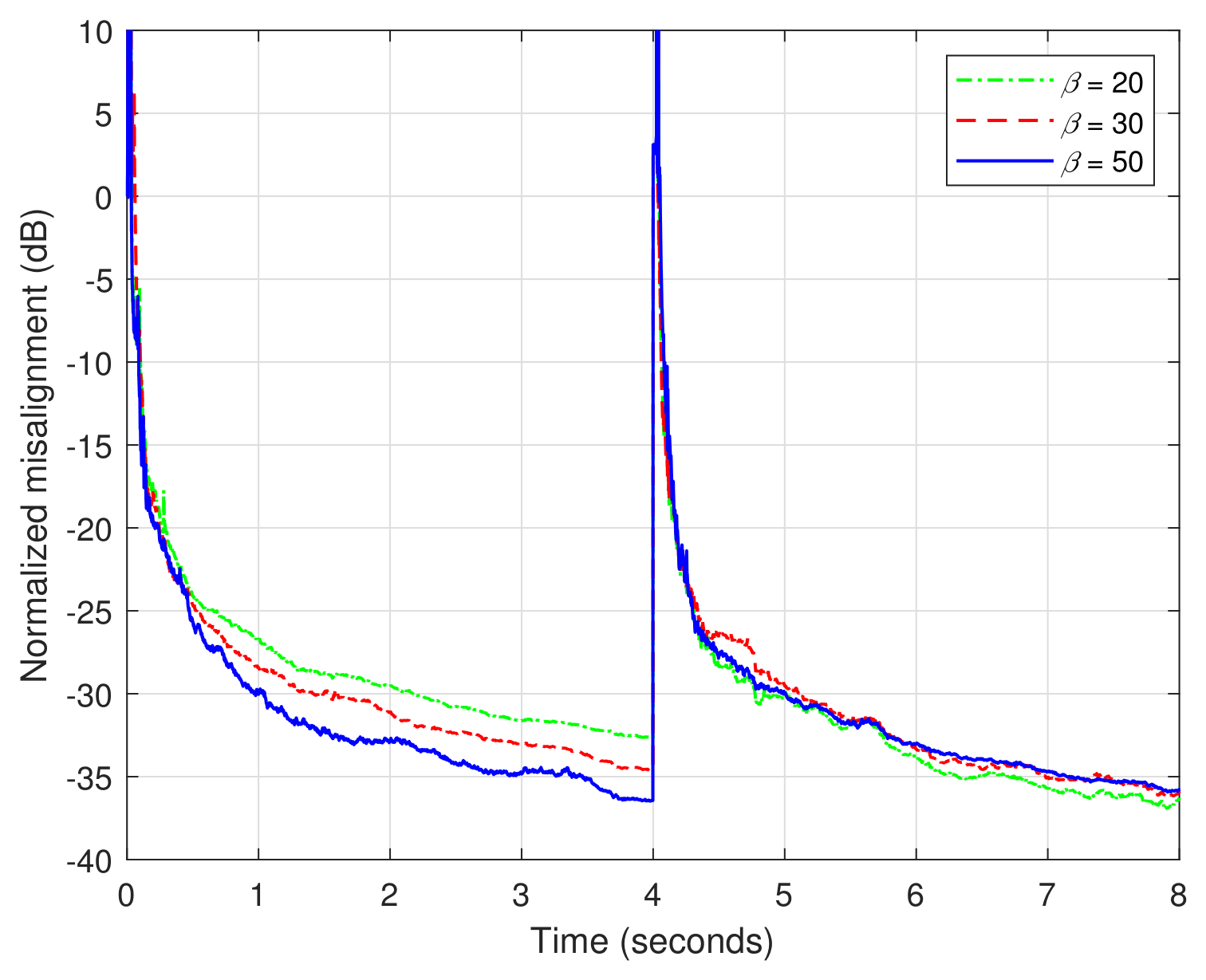
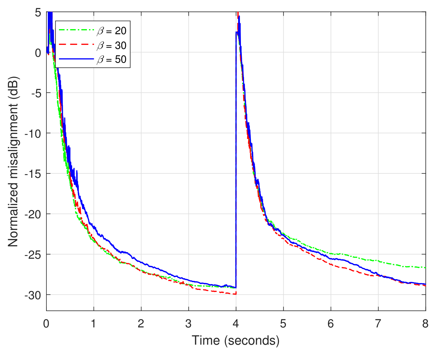
should be much larger than one, e.g., on the order of tens. In
Figure 9, the influence of
on the overall performance of the RLS-FOT-VFFs algorithm is not very relevant, especially in terms of tracking. Therefore, a value in the vicinity of
or
could represent a practical setting. This is also in consistence with the results reported in [
49], for the RLS-VFF counterpart.
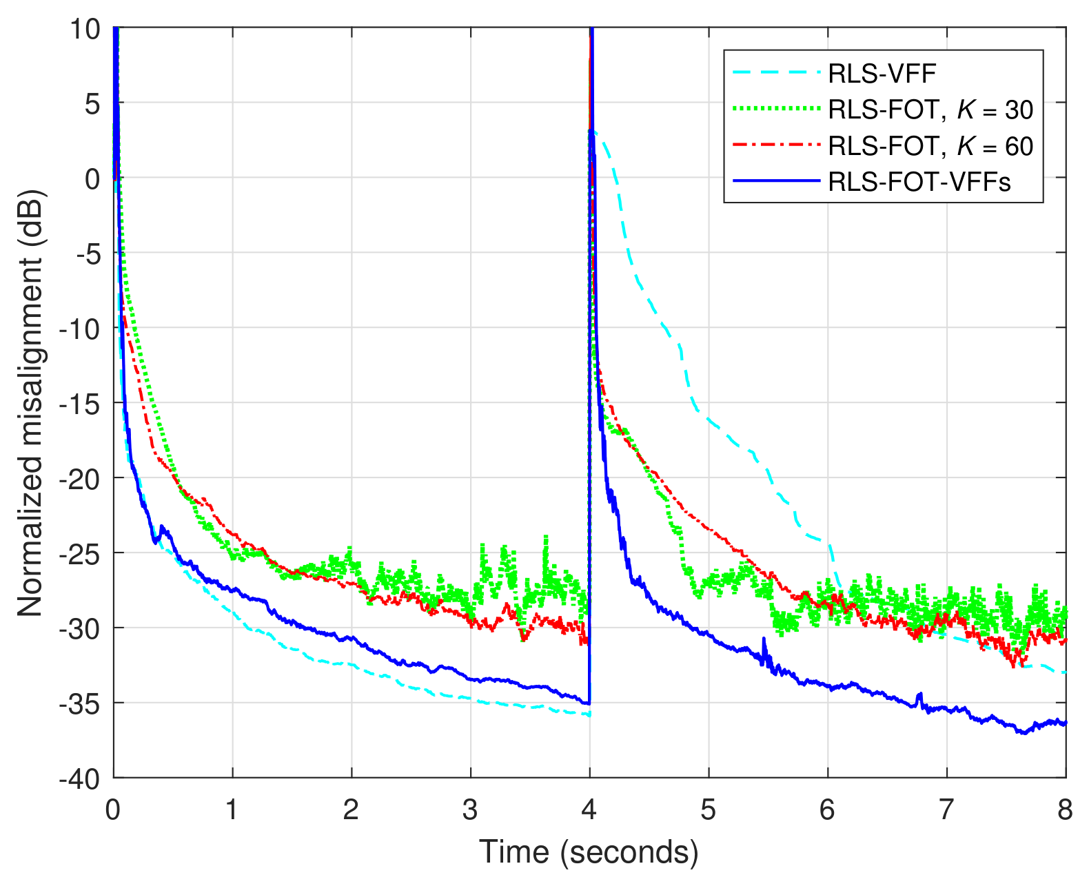
The next experiment from this first set is dedicated to the comparison with the RLS-FOT algorithm from [
36] and the RLS-VFF filter from [
49]. As explained before, these two algorithms represent recent benchmarks for the decomposition-based versions, respectively for the VFF-based counterparts. In
Figure 10, the RLS-FOT algorithm [
36] uses the same decomposition setup as the proposed RLS-FOT-VFFs (i.e.,
and
), while different values of the forgetting factors are used, by setting the parameter
K in (
42). Also, the RLS-VFF algorithm [
49] uses the same
as the proposed RLS-FOT-VFFs, while its (single) forgetting factor is evaluated as in (
43), considering a single (long-length) filter with
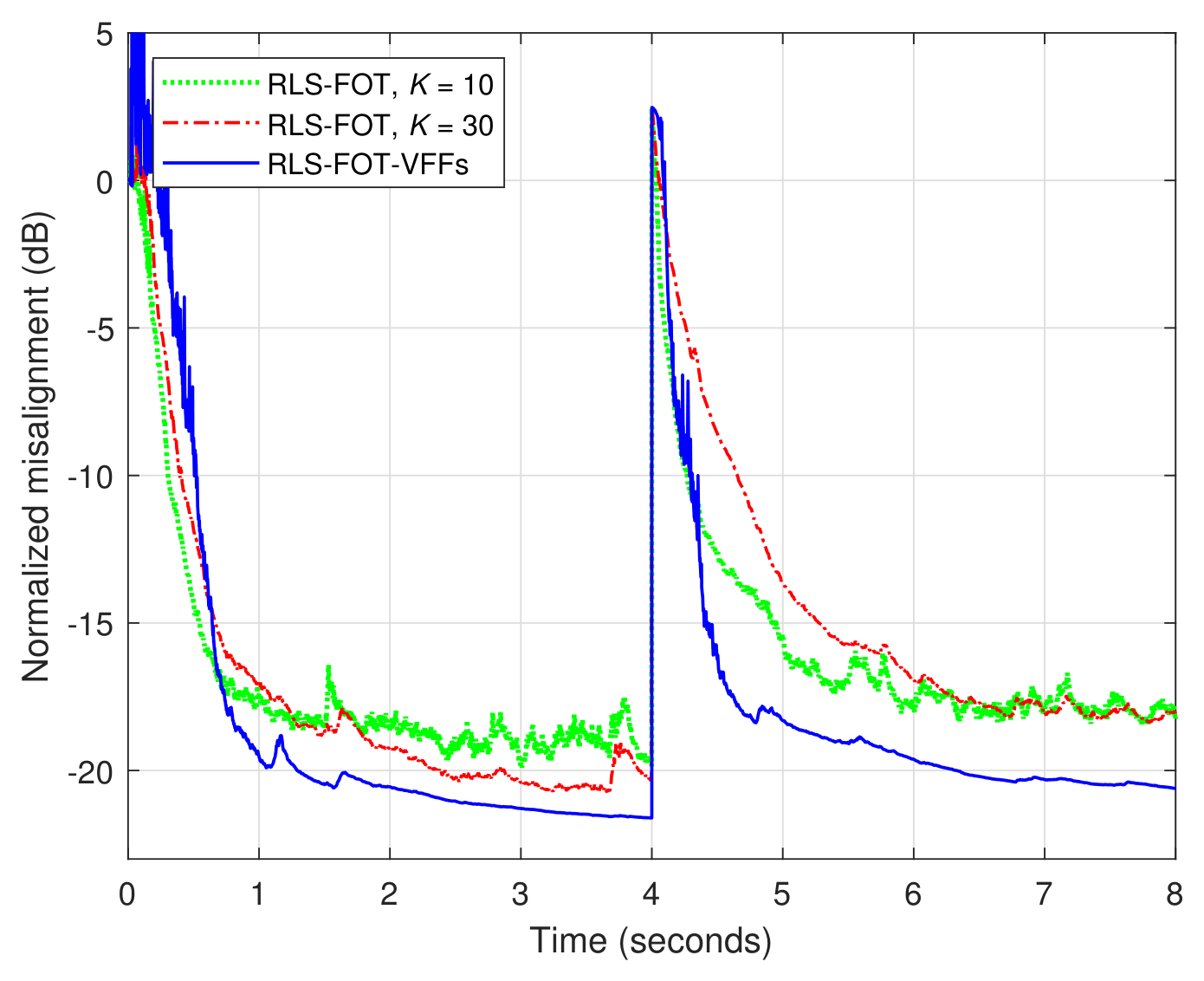
L coefficients. Since the RLS-FOT-VFFs algorithm operates with shorter adaptive filters, its tracking capability is significantly better, as compared to the RLS-VFF benchmark. Also, the proposed version reaches a lower misalignment level (i.e., a better accuracy of the estimate), as compared to the RLS-FOT counterpart, which uses constant forgetting factors. In order to improve the accuracy of the RLS-FOT algorithm, its forgetting factors should be increased (e.g., by increasing the value of
K), while paying in terms of the tracking behavior. Overall, the proposed RLS-FOT-VFFs algorithm obtains a better balance in terms of these performance criteria.
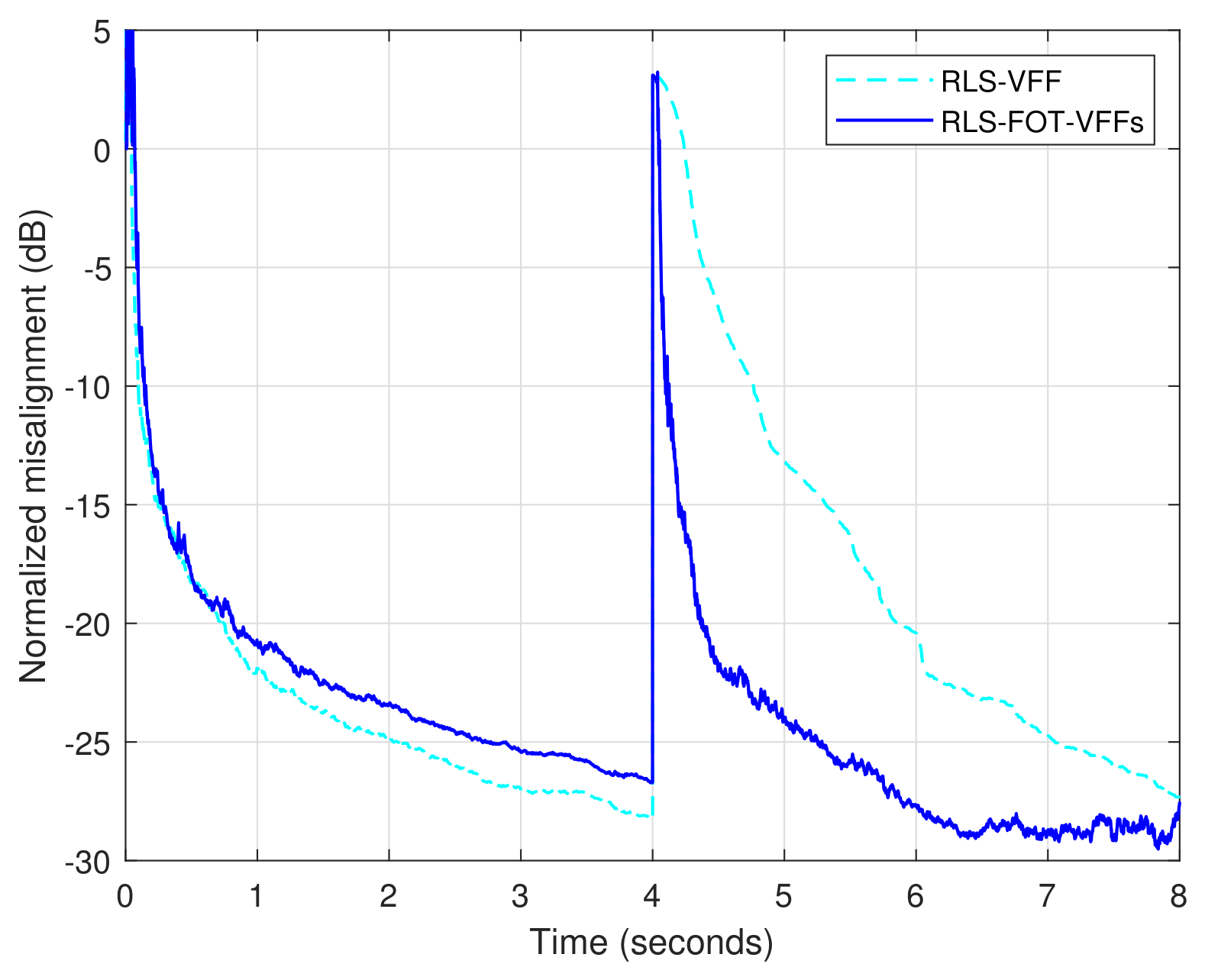
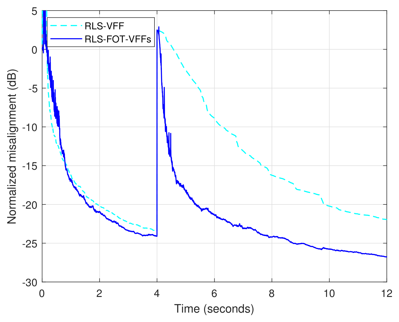
The advantages of the decomposition-based algorithm are also valid for different SNR conditions. As an example, in
Figure 11, the proposed RLS-FOT-VFFs algorithm is compared to the RLS-VFF counterpart from [
49], under a noisy scenario, with
dB. Both algorithms achieve a similar accuracy at steady-state (i.e., a similar misalignment level), while the FOT-based algorithm has a better tracking reaction, due to the combination of shorter adaptive filters.
In the second set of experiments, the longer (and less sparse) acoustic impulse response from
Figure 4b is considered, with the length
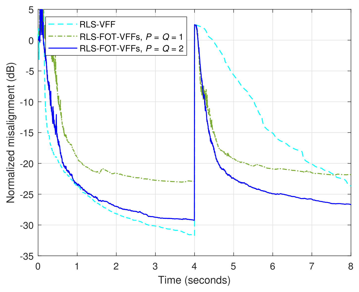
. First, the influence of the decomposition parameters
P and
Q is assessed in
Figure 12, while using
. Here, the RLS-VFF algorithm from [
49] is considered as a comparison benchmark. Both algorithms use
for the estimation of
from (
41). It can be noticed that the proposed RLS-FOT-VFFs algorithm has a significantly better tracking capability, as compared to the RLS-VFF counterpart, since the decomposition-based version combines shorter adaptive filters. In terms of misalignment (i.e., accuracy), the performance of the RLS-FOT-VFFs algorithm is improved for
(which corresponds to
, as compared to the case when
. Nevertheless, even when using the smallest values of
P and
Q (i.e., the lowest complexity), the proposed algorithm reaches a misalignment level below
dB, while still outperforming the RLS-VFF version [
49] in terms of the tracking capability.
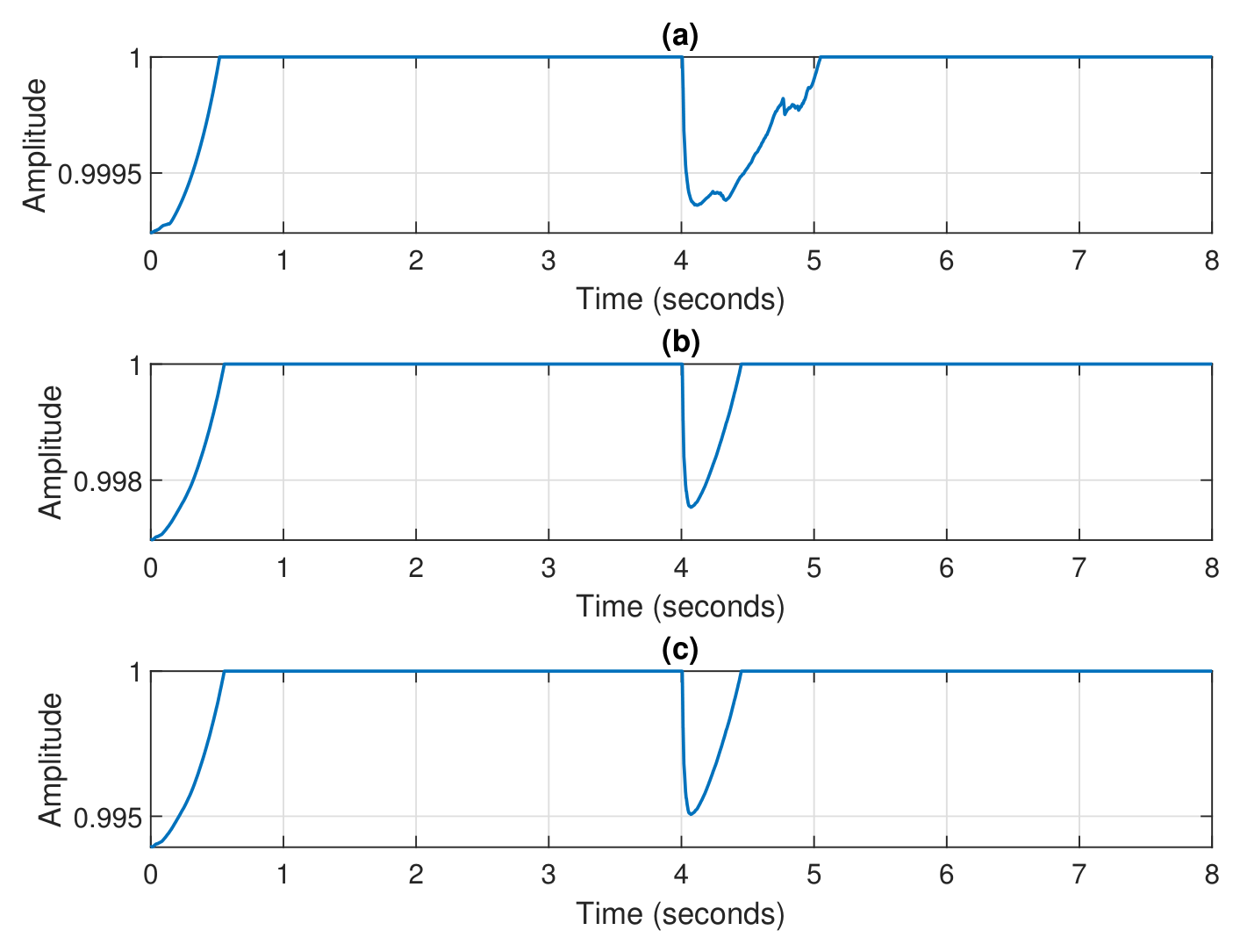
Related to this experiment, the time-dependent forgetting factors of the RLS-VFF and RLS-FOT-VFFs algorithms are depicted in
Figure 13. In the case of RLS-VFF algorithm [
49], its forgetting factor is evaluated based on (
43) and it operates on a single (long-length) filter with
coefficients. The forgetting factors of the proposed RLS-FOT-VFFs algorithm (with
and
) are evaluated based on (
36)–(
39). Due to the decomposition settings from
Figure 12, it results that
, which correspond to two of the component filters, with the lengths
. Also, we have
, related to the other two component filters, having the lengths
. The faster tracking capability of the RLS-FOT-VFFs algorithm can be assessed from
Figure 13b,c, due to the evolution of its VFFs, as compared to the behavior of the RLS-VFF algorithm [
49] from
Figure 13a, where
has a slower tracking reaction.
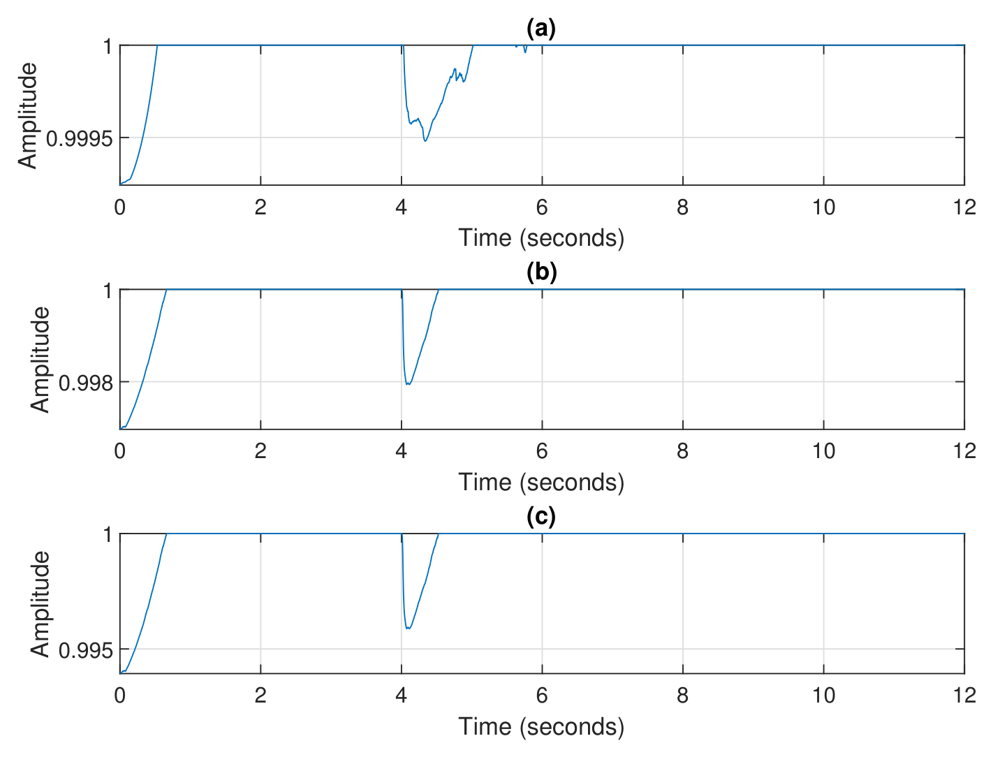
The previous experiment related to
Figure 12 and
Figure 13 is reconsidered under a noisy scenario, with
dB, and the results are shown in
Figure 14 and
Figure 15, respectively. As we can notice in
Figure 14, the proposed RLS-FOT-VFFs algorithm (using
and
) clearly outperforms the RLS-VFF counterpart from [
49] in terms of the tracking capability, while reaching a similar misalignment level at steady-state. This behavior is also supported in
Figure 15, by the evolution of the time-dependent forgetting factors corresponding to the comparing algorithms.
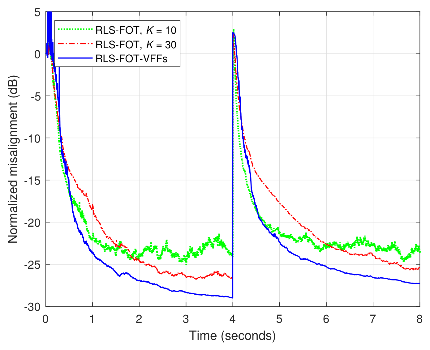
The main feature of the proposed RLS-FOT-VFFs algorithm, as compared to the recently developed RLS-FOT version from [
36], consists in a better balance between the main performance criteria, i.e., accuracy versus tracking. This is supported in
Figure 16, where both algorithms involve the same decomposition setup (with
and
), while the RLS-FOT algorithm [
36] uses different constant forgetting factors, by tuning the value of
K in (
42). As expected, larger values of the forgetting factors (i.e., a larger value of
K) improve the accuracy of the RLS-FOT algorithm, with the cost of a slower tracking reaction. Reducing the value of
K results in using smaller values of the forgetting factors, which improve the tracking behavior, but paying with a higher misalignment level. Overall, it can be noticed that the RLS-FOT-VFFs algorithm achieves a better compromise between these performance features.
A similar conclusion can be reached when using a smaller value of the decomposition parameter
R, which corresponds to a lower computational complexity. In
Figure 17, the previous experiment is repeated, but using
. The results outline the same advantageous behavior of the proposed RLS-FOT-VFFs algorithm, in terms of its better performance balance, obtaining a good misalignment level (below
dB), together with a fast tracking reaction.
Finally, the influence of the smoothing factor used for the estimation of
from (
41) is assessed. In
Figure 18, different values of
(on the order of tens) are considered, while the decomposition settings of the RLS-FOT-VFFs algorithm are
and
. It can be noticed that the proposed algorithm is fairly robust to the selection of
, which is the only parameter to be set related to the VFFs’ part of the filter. This also represents a practical asset of the RLS-FOT-VFFs algorithm.




 ,
,