1. Introduction
Tunnel linings are key structural components for maintaining the safety and serviceability of underground transportation systems. During long-term operation, tunnel linings may suffer from cracking, leakage, joint opening, excessive convergence, local deterioration, and stiffness degradation caused by ground movement, surcharge loading, water pressure, construction disturbance, and material aging. For circular tunnel linings, analytical methods have long been used to clarify the relationship between external loads, ground–lining interactions, internal force distribution, and lining deformation. Early studies by Morgan [
1], Muir Wood [
2], and Einstein and Schwartz [
3] established important theoretical foundations for circular tunnel lining analysis. Later studies further extended analytical solutions to jointed shield-driven linings, elastic foundation models, surcharge-induced responses, and various ground–lining interaction conditions [
4,
5,
6]. These analytical approaches remain valuable because they provide explicit mechanical insight and efficient benchmark solutions for preliminary design and numerical verification.
For existing shield tunnels with excessive deformation or structural defects, steel plate strengthening has been widely investigated as an effective rehabilitation method. Bonded steel plates or steel–concrete composite layers can enhance the overall stiffness and bearing capacity of damaged segmental linings. Zhang et al. [
7] proposed a robust retrofitting design framework for segmental tunnel linings strengthened with steel plates. Zhang et al. [
8] investigated the structural behavior of reinforced concrete tunnel segments strengthened by a steel–concrete composite layer. Zhai et al. [
9] developed an analytical solution for steel plate-strengthened circular tunnels considering different interface slip modes, while their subsequent numerical study further examined the composite behavior of over-deformed segmental tunnel linings strengthened by bonded steel plates [
10]. Liu et al. [
11] also emphasized that the steel–concrete interface plays an important role in the deformation compatibility, load transfer, and failure mechanism of strengthened tunnel linings. These studies indicate that steel-based strengthening can effectively improve tunnel lining performance, but the stress redistribution between the original lining and the added steel layer needs to be properly evaluated.
Compared with ordinary flat steel plates, corrugated steel plates have attracted increasing attention in tunnel and underground engineering because of their high stiffness-to-weight ratio, rapid assembly, strong deformation adaptability, and favorable construction efficiency. Xu et al. [
12] investigated the application of fabricated corrugated steel plates in subway tunnel supporting structures through engineering monitoring and numerical simulation. Guo et al. [
13] studied corrugated steel–concrete prefabricated support structures for underground engineering. Zhao et al. [
14] systematically investigated the mechanical properties and damage mechanism of corrugated steel plate–concrete composite structures as primary tunnel supports. Qin et al. [
15] further reported a full-scale investigation on the reinforcement of an impaired shield tunnel structure using stainless steel corrugated plates. These studies demonstrate the potential of corrugated steel components in tunnel support and strengthening, especially in terms of rapid construction and composite load-bearing behavior.
The mechanical response of corrugated steel structures is strongly affected by their geometric corrugation. The corrugation induces directional stiffness differences, making the structure mechanically anisotropic even when the base steel material is isotropic. In structural mechanics, replacing corrugated panels with equivalent orthotropic plates or shells is a common simplification for reducing modeling complexity while retaining the dominant stiffness characteristics. Xia et al. [
16] developed equivalent models for corrugated panels and showed that corrugated structures can be approximately represented by orthotropic plate models. Cheon and Kim [
17] proposed an equivalent plate model for corrugated-core sandwich panels based on homogenization and energy equivalence. Aoki and Maysenhölder [
18] experimentally and numerically assessed the equivalent orthotropic thin-plate model for corrugated panels. These studies provide theoretical support for using equivalent orthotropic material properties to represent corrugated steel layers in simplified structural analysis.
Despite these advances, most existing studies on corrugated steel structures in tunnels focus on field application, experimental behavior, numerical simulation, or component-level mechanical performance. Analytical solutions for corrugated steel–concrete composite tunnel linings remain relatively limited. Existing analytical studies on tunnel linings mainly focus on homogeneous circular linings, jointed segmental linings, ground–lining interactions, surcharge loading, composite linings under seismic waves, imperfect interface bonding, non-axisymmetric loading, or flat steel plate strengthening. For example, Zhao et al. [
19] developed analytical solutions for circular composite-lined tunnels with arbitrary layer linings under obliquely incident seismic waves; Ahn and Pouya [
20] proposed an analytical solution for circular tunnel–lining interactions with elastic contact; Zou et al. [
21] investigated the response of circular tunnels with imperfect interface bonding in layered ground; and Li et al. [
22] derived an elastic–plastic analytical solution for circular tunnels under non-axisymmetric conditions. However, the combined problem of a circular tunnel lining composed of isotropic concrete and an equivalent orthotropic corrugated steel layer has not been sufficiently addressed, especially under non-uniform external pressure. Moreover, the effects of layer arrangement and corrugation-induced stiffness enhancement on the stress redistribution mechanism are still not fully clarified.
From the perspective of symmetry, a circular tunnel lining under uniform pressure exhibits an axisymmetric response, whereas non-uniform external pressure introduces asymmetric harmonic components. For corrugated steel–concrete composite linings, different radial layer arrangements further affect the stress redistribution mechanism because the equivalent orthotropic steel layer changes the stiffness distribution of the circular lining. However, analytical studies that explicitly distinguish the axisymmetric response from the asymmetric harmonic response of corrugated steel–concrete composite tunnel linings remain limited.
The novelty of this study lies in establishing an analytical framework that separates the axisymmetric response from the asymmetric harmonic response of a corrugated steel–concrete composite tunnel lining. By introducing an equivalent cylindrically orthotropic representation of corrugated steel, the proposed solution enables the effects of layer arrangement, stiffness ratio, and non-uniform external pressure on symmetry-related stress redistribution to be evaluated in a unified manner. The analytical solution is verified by finite element models and then used to clarify the mechanical role of the corrugated steel layer under different structural and loading conditions.
The main contributions of this study are as follows:
- (1)
A closed-form analytical solution is developed for corrugated steel–concrete composite tunnel linings by decomposing the response into an axisymmetric component and an asymmetric harmonic component.
- (2)
The corrugated steel layer is represented as an equivalent cylindrically orthotropic material, which enables the corrugation-induced stiffness enhancement to be incorporated into the analytical formulation.
- (3)
The effects of layer arrangement, stiffness ratio, and burial depth on symmetry-related stress redistribution are investigated.
- (4)
The analytical solution is verified using finite element models, providing a benchmark for evaluating the mechanical behavior of corrugated steel–concrete composite tunnel linings.
2. Analytical Model
In this section, an analytical formulation is developed for a two-layer corrugated steel–concrete composite tunnel lining subjected to equivalent external pressure. The corrugated steel layer is represented as an equivalent cylindrically orthotropic material, while the concrete layer is treated as an isotropic elastic material. The governing equations, displacement and stress functions, boundary conditions, and interface continuity conditions are derived in the polar coordinate system. The formulation is applicable to both uniform external pressure and non-uniform external pressure expressed by harmonic terms and provides the theoretical basis for the finite element validation and parametric analyses presented in the following sections.
2.1. Problem Description and Basic Assumptions
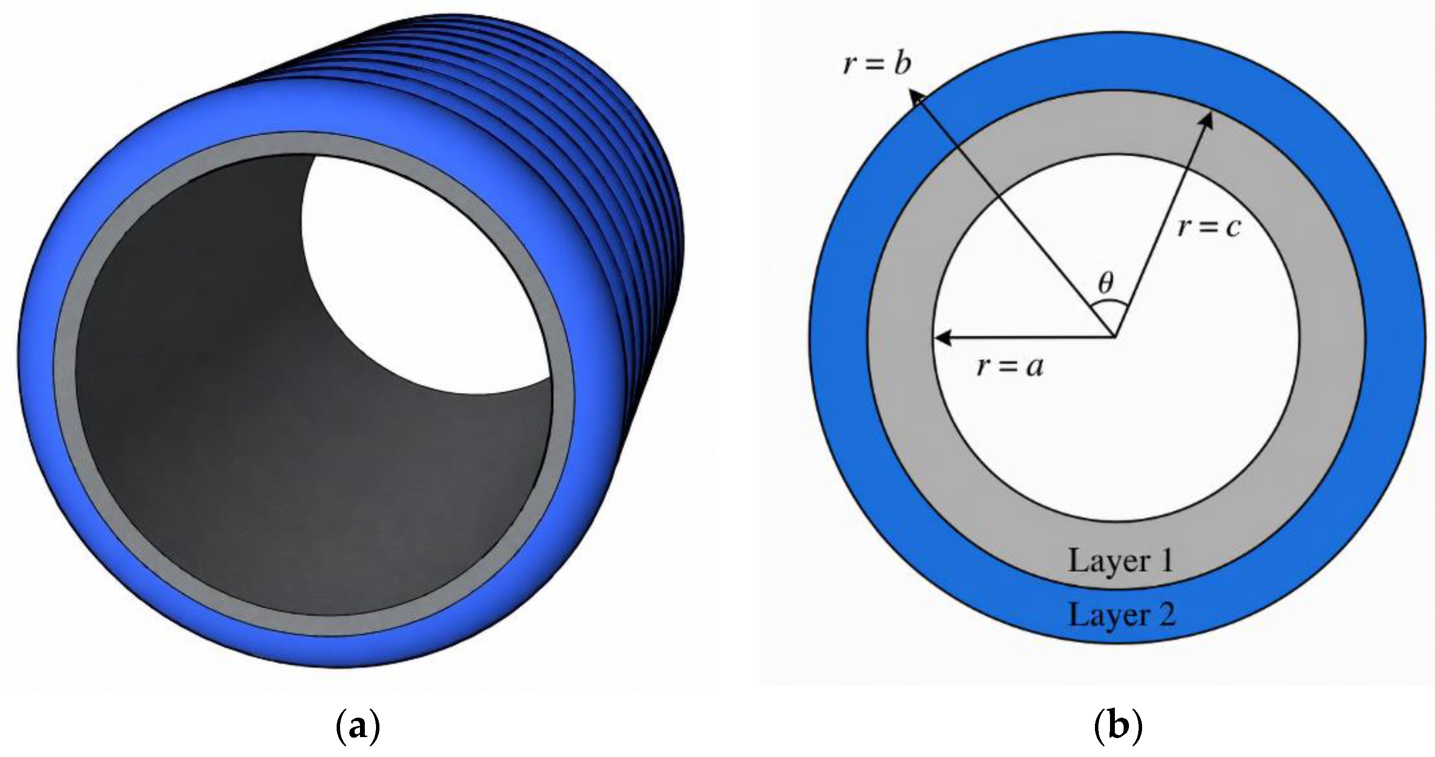
A two-layer circular composite tunnel lining is considered, as shown in
Figure 1.
Figure 1a illustrates the three-dimensional configuration of the corrugated steel–concrete composite lining, while
Figure 1b shows the corresponding cross-sectional analytical model in the polar coordinate system. The inner radius and outer radius of the lining are denoted by a and b, respectively, and the steel–concrete interface is located at r = c. A polar coordinate system (r,θ,z) is adopted, where r is the radial coordinate, θ is the circumferential coordinate, and z is the longitudinal direction of the tunnel.
The proposed formulation can describe two different steel–concrete layer arrangements. In Arrangement I, the corrugated steel layer is placed on the inner side and the concrete layer is located outside. In Arrangement II, the concrete layer is placed inside and the corrugated steel layer is located outside. The same analytical framework is applicable to both arrangements by assigning the corresponding material properties to the inner and outer layers.
The following assumptions are introduced:
- (1)
The tunnel lining is treated as an infinitely long circular structure, and the mechanical response is described under the plane-strain condition.
- (2)
The concrete layer is modeled as an isotropic linear elastic material.
- (3)
The corrugated steel layer is represented by an equivalent cylindrically orthotropic material.
- (4)
The steel–concrete interface is assumed to be perfectly bonded. Therefore, the radial displacement, tangential displacement, radial stress, and shear stress are continuous across the interface.
- (5)
The external ground action is simplified as an equivalent non-uniform normal pressure acting on the outer boundary. The tangential ground traction is neglected.
Under these assumptions, the analytical solution is derived for the radial displacement ur, tangential displacement , radial stress , hoop stress , and shear stress . The analytical model is developed under the plane-strain assumption. Therefore, it is intended to represent a tunnel section where the geometry, material properties, and external pressure vary slowly along the longitudinal direction. This assumption is more appropriate for tunnel regions sufficiently far from portals, construction joints, segmental discontinuities, and localized loading zones. Longitudinal effects and local variations along the tunnel axis are not explicitly included in the present formulation.
2.2. Equivalent Orthotropic Representation of Corrugated Steel
Due to the corrugated geometry, the stiffness of corrugated steel is direction-dependent. Instead of explicitly modeling the corrugation profile, the corrugated steel layer is simplified as an equivalent cylindrically orthotropic layer. The principal material directions are taken as the radial, circumferential, and longitudinal directions of the tunnel.
The equivalent elastic constants of the corrugated steel layer are denoted by
where
,
and
are the equivalent elastic moduli in the radial, circumferential, and longitudinal directions, respectively. To quantify the corrugation-induced stiffness enhancement, the circumferential-to-radial stiffness ratio is defined as
When α = 1, the steel layer degenerates into an ordinary flat steel plate without corrugation-induced circumferential stiffness enhancement. When α > 1, the enhanced circumferential stiffness of the corrugated steel layer is represented. The longitudinal stiffness ratio is defined as
where
Es is the elastic modulus of the steel material. The corrugated steel layer is not modeled by explicitly resolving each corrugation. Instead, it is represented as an equivalent cylindrically orthotropic continuum. In this representation,
,
, and
denote the homogenized effective radial, circumferential, and longitudinal stiffnesses of the corrugated steel layer, respectively. These parameters should be interpreted as effective continuum stiffnesses rather than as the intrinsic elastic constants of the base steel material.
The stiffness ratio
is introduced to characterize the circumferential stiffness enhancement associated with the corrugated configuration, while the longitudinal stiffness ratio
is used to describe the relative longitudinal stiffness of the equivalent corrugated steel layer under the plane-strain condition. For a specific corrugated steel profile, these equivalent stiffness parameters can be obtained from unit-cell homogenization, micromechanics-based homogenization, mechanical testing, or detailed finite element modeling of the actual corrugation geometry, including corrugation depth, pitch, developed length, and plate thickness [
23,
24,
25]. The effective stiffnesses can then be obtained by applying independent radial, circumferential, and longitudinal deformation modes to the unit cell, or alternatively by mechanical testing or detailed finite element modeling of the actual corrugation geometry. In the present study,
and
are used as dimensionless parametric indicators to investigate the influence of corrugation-induced orthotropic stiffness rather than as calibrated values for a specific commercial corrugated steel product.
For the equivalent orthotropic steel layer, the three-dimensional compliance relation in the (z,r,
θ) coordinate system is expressed as
Under the plane-strain condition,
By inverting the compliance matrix, the reduced stiffness relation for the r-θ plane can be written as
where C
22, C
23, C
33, and C
44 are the equivalent plane-strain stiffness coefficients of the orthotropic corrugated steel layer.
2.3. Governing Equations and General Solutions
In polar coordinates, the strain–displacement relations are
In the absence of body forces, the equilibrium equations are
For the isotropic concrete layer, the plane-strain constitutive relation is written as
where
and
Here, Ec and are the elastic modulus and Poisson’s ratio of concrete, respectively.
Because the governing equations are linear, the total solution can be expressed as the superposition of an axisymmetric component and harmonic components. The external pressure can be expanded as
In this Fourier representation, the constant term
denotes the axisymmetric pressure component, which produces an axisymmetric response of the circular lining. The harmonic terms with
represent non-axisymmetric pressure components and may induce asymmetric stress and displacement fields. Therefore, a general non-uniform external pressure can be interpreted as the superposition of an axisymmetric component and a series of asymmetric harmonic components. For the axisymmetric component in the isotropic layer, the radial displacement is expressed as
where A
0 and B
0 are unknown coefficients. The corresponding radial and hoop stresses are
For the
n-th harmonic component in the isotropic layer, the displacement field is assumed as
For the isotropic layer, the characteristic exponents are
The coefficient β
j is given by
The corresponding stress components can be written as
where
For the equivalent orthotropic corrugated steel layer, the axisymmetric displacement is expressed as
where
The corresponding stresses are
For the
n-th harmonic component in the orthotropic layer, the displacement field has the same form as that of the isotropic layer:
For the orthotropic layer, the characteristic exponents p
j are determined from
For each root p
j, the coefficient β
j is
The corresponding stress components are also written as
where
2.4. Boundary Conditions and Solution Procedure
The inner boundary of the lining is assumed to be traction-free:
The outer boundary is subjected to an equivalent non-uniform normal pressure:
For a general non-uniform normal pressure acting on the outer boundary, the pressure distribution can be expanded into a Fourier series as
The coefficients can be specified according to the external pressure distribution. Owing to the linearity of the governing equations, each harmonic component can be solved independently and then superposed. The above Fourier-series representation indicates that the proposed analytical framework is not restricted to a single harmonic component. Under the linear-elastic assumption, different harmonic components can be solved independently and then superposed when the corresponding pressure coefficients are available.
For a typical tunnel section subjected to different vertical and horizontal ground pressures, the second-order harmonic component has a direct mechanical interpretation. If the equivalent vertical and horizontal pressures are denoted by and , respectively, the normal pressure acting on the circular boundary can be approximately represented as Using the trigonometric identities and , this expression becomes .
Thus, the difference between vertical and horizontal ground pressures gives rise to a zero-order axisymmetric component and a second-order cosine harmonic component. This explains why the second-order harmonic term is selected as a representative tunnel-type non-uniform loading mode in the present validation and parametric analyses.
At the steel–concrete interface (r = c), the perfect-bond condition requires the continuity of displacement and traction:
where the superscripts “(−)” and “(+)” denote the inner and outer sides of the interface, respectively. It should be noted that the hoop stress
is not required to be continuous across the interface. Therefore, a jump in hoop stress may appear at the steel–concrete interface when the two layers have different stiffness properties.
Because the governing equations are linear, the total solution is obtained by superposing the axisymmetric solution and the harmonic solutions. Accordingly, the total mechanical response can be regarded as the superposition of an axisymmetric solution and a set of asymmetric harmonic solutions. This decomposition provides a direct way to evaluate symmetry-related stress redistribution in circular composite tunnel linings under general non-uniform external pressure. For the axisymmetric component, four unknown coefficients are involved: two coefficients for the inner layer and two coefficients for the outer layer. These coefficients are determined by the inner boundary condition, the outer boundary condition, and the two interface conditions for radial displacement and radial stress.
For each non-axisymmetric harmonic component, the displacement and stress fields of each layer contain eight unknown coefficients, corresponding to the cosine and sine terms of the four characteristic roots. Therefore, a system of sixteen linear algebraic equations is constructed for each harmonic order. These equations are obtained from the two inner boundary conditions, four interface continuity conditions for the cosine terms, four interface continuity conditions for the sine terms, and the two outer boundary conditions for each trigonometric component.
After solving the unknown coefficients for the axisymmetric and harmonic components, the complete displacement and stress fields are obtained as
For the tunnel loading condition considered in this study, only the zero-order term and the second-order harmonic term are required. Thus, the proposed solution can describe both uniform external pressure and equivalent non-uniform external pressure in a unified form. When the material properties of the two layers are set to be identical, the solution degenerates into that of a single-layer homogeneous circular lining. When p
1b = 0, the loading condition degenerates into uniform external pressure. In the numerical examples and parametric analyses presented in
Section 3 and
Section 4, the general formulation is reduced to the zero-order term and the second-order cosine term to represent an equivalent non-uniform tunnel pressure. Therefore, the applied pressure is written as
.
Although the formulation is derived for a general Fourier-type non-uniform external pressure, the verification and parametric analyses in the following sections focus on the second-order cosine harmonic component. This loading form is used to represent the difference between vertical and horizontal ground pressures around a circular tunnel, where is the axisymmetric component and is the asymmetric harmonic component.
3. Verification of Symmetric and Asymmetric Response Components
To verify the proposed analytical formulation, three validation cases are considered. The first two cases correspond to axisymmetric responses under uniform external pressure, while the third case involves a non-uniform pressure component and is used to verify the asymmetric harmonic response. In this way, both the symmetric and asymmetric parts of the proposed solution are examined.
3.1. Finite Element Model and Validation Strategy
To verify the accuracy of the proposed analytical solution, finite element method (FEM) models were established and compared with the analytical results under different material and loading conditions. Three validation cases were considered, as summarized in
Table 1. Case V1 corresponds to a single-layer homogeneous circular lining under uniform external pressure. This case was used to verify the degeneration of the proposed two-layer formulation to the classical homogeneous annular lining problem. Case V2 corresponds to a two-layer composite lining under uniform external pressure, in which the inner layer is isotropic, and the outer layer is equivalent cylindrically orthotropic. Case V3 further considers the two-layer composite lining under non-uniform external pressure. Through these three cases, the analytical solution was verified progressively from a homogeneous axisymmetric problem to a composite non-axisymmetric problem. For the axisymmetric validation cases, the FEM model was established using an axisymmetric formulation. For the non-uniform pressure case, a two-dimensional plane-strain FEM model was used to capture the angular variation in stress and displacement. In both models, the concrete layer was defined as an isotropic linear-elastic material, while the corrugated steel layer was defined as an equivalent orthotropic material consistent with the analytical model. The material principal directions of the orthotropic steel layer were aligned with the radial, circumferential, and longitudinal directions of the tunnel lining. Accordingly, the radial, circumferential, and longitudinal elastic moduli were assigned as
,
, and
, respectively. The steel–concrete interface was modeled using shared nodes, so that displacement compatibility was directly enforced at the interface. For the non-uniform pressure case, the external pressure was applied along the outer boundary according to the angular coordinate, consistent with the Fourier-type loading expression used in the analytical solution.
For Cases V1 and V2, the structural response is axisymmetric because the external pressure is uniformly distributed along the outer boundary. Therefore, a one-dimensional axisymmetric finite element model was adopted. In this model, the radial displacement
ur is the only nodal degree of freedom, and the strain vector is written as
The element stiffness matrix was obtained from the strain energy of the radial and circumferential strain components. The external pressure was applied as an equivalent nodal force on the outer boundary. For the two-layer model, the concrete and corrugated steel layers were discretized separately, but the interface node was shared by the two adjacent layers. Therefore, the radial displacement continuity at the steel–concrete interface was automatically satisfied.
For Case V3, the external pressure was expressed as a second-order harmonic function,
which produces a non-axisymmetric stress and displacement field. Therefore, a two-dimensional plane-strain finite element model was established using four-node quadrilateral elements. The inner boundary was traction-free, while the non-uniform pressure was applied to the outer boundary according to the angular position. The steel–concrete interface was modeled by shared nodes, corresponding to the perfect-bond assumption in the analytical model. The corrugated steel layer was represented by the same equivalent cylindrically orthotropic material parameters as those used in the analytical solution.
A mesh convergence study was conducted before comparing the analytical and finite element results. For Cases V1 and V2, the radial mesh was refined from 100 to 800 elements. For Case V1, when the number of elements was increased from 400 to 800, the changes in the maximum radial stress and maximum hoop stress were only 0.0071% and 0.0089%, respectively. For Case V2, the corresponding changes were 0.0579% and 0.00075%, respectively. These results indicate that the one-dimensional axisymmetric FEM models are sufficiently mesh-independent.
For Case V3, four two-dimensional meshes were considered by increasing the radial and circumferential discretization densities from 1320 to 20,640 elements. When the mesh was refined from 11,700 to 20,640 elements, the changes in the maximum radial stress, maximum hoop stress, maximum shear stress, and maximum radial displacement were 0.316%, 1.037%, 0.253%, and 1.088%, respectively. The change in the maximum hoop stress of the concrete layer was 1.335%. Therefore, the final mesh was considered sufficiently accurate for the non-axisymmetric validation case.
Based on the convergence study, the mesh with and was adopted for the one-dimensional axisymmetric validation cases V1 and V2. For the two-dimensional validation case V3, the mesh with , , and was adopted. The following subsections compare the analytical and FEM results for the three validation cases.
3.2. Validation Case V1: Single-Layer Homogeneous Lining Under Uniform Pressure
The first validation case was designed to verify the degeneration of the proposed analytical solution to a single-layer homogeneous circular lining. In this case, the material properties of the inner and outer regions were set to be identical, so that the two-layer formulation degenerates into a homogeneous annular lining. Although the interface position r = c is still marked in the figure for consistency with the composite model, it has no physical meaning in this validation case and does not introduce any material discontinuity. This case is therefore used to verify that the proposed formulation can correctly reproduce the axisymmetric response of a geometrically symmetric homogeneous circular lining under uniform external pressure.
The inner and outer radii of the lining were set as a = 2.7 m and b = 3.0 m, respectively. A uniform external pressure of p0 = 1 MPa was applied to the outer boundary, while the inner boundary was traction-free. The finite element model was established using a one-dimensional axisymmetric formulation, and the same plane-strain material parameters were used in both the analytical and finite element calculations.
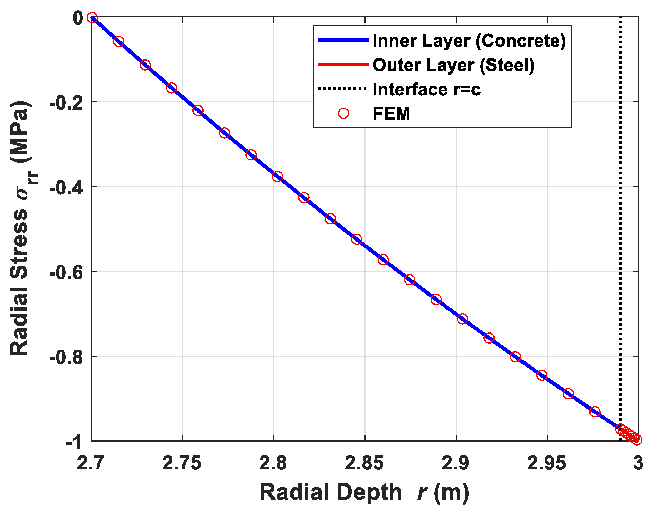
Figure 2 shows the comparison of radial stress distributions obtained from the analytical solution and the FEM model. The radial stress varies smoothly from approximately zero at the inner boundary to −1.0 MPa at the outer boundary, satisfying the prescribed boundary conditions. The FEM results agree very well with the analytical curve over the entire radial range. No stress discontinuity is observed at the marked interface position r = c, confirming that the two-layer formulation correctly degenerates into a homogeneous single-layer solution when identical material properties are assigned to both regions.
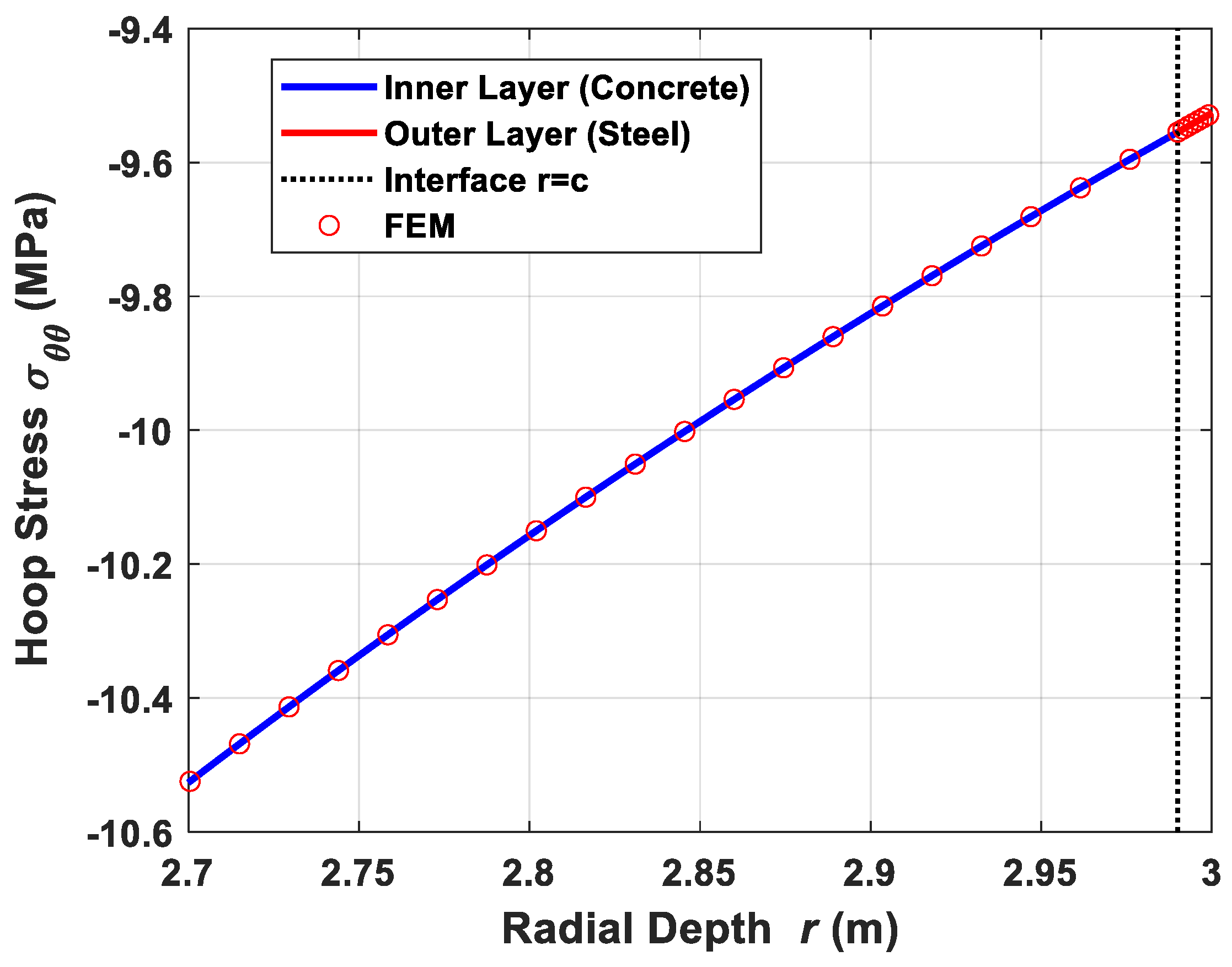
Figure 3 compares the hoop stress distributions. The hoop stress is compressive throughout the lining thickness and reaches its largest magnitude near the inner boundary. The magnitude of the hoop stress gradually decreases toward the outer boundary. The analytical and FEM results are almost coincident, indicating that the proposed analytical solution can accurately reproduce the classical stress state of a homogeneous thick circular lining under uniform external pressure.
The agreement in both radial and hoop stresses demonstrates that the basic axisymmetric part of the analytical formulation is correct. Therefore, the proposed solution can reliably degenerate to the single-layer homogeneous case, which provides the foundation for the subsequent validation of the two-layer composite lining.
3.3. Validation Case V2: Two-Layer Composite Lining Under Uniform Pressure
The second validation case was conducted to verify the analytical solution for a two-layer composite lining under axisymmetric loading. In this case, the inner layer was modeled as an isotropic concrete layer, and the outer layer was modeled as an equivalent cylindrically orthotropic corrugated steel layer. The inner radius, interface radius, and outer radius were a = 2.7 m, c = 2.99 m, and b = 3.0 m, respectively. A uniform external pressure of p0 = 1 MPa was applied to the outer boundary, while the inner boundary was traction-free. Since the loading condition is axisymmetric, only the zero-order terms of the analytical solution are involved. This case is therefore used to verify the axisymmetric response component of the proposed solution and to examine whether the formulation can correctly capture stress redistribution in a geometrically symmetric but materially layered circular lining.
The finite element model was established using the same one-dimensional axisymmetric formulation as in Case V1. The concrete and corrugated steel layers were discretized separately, but the nodes at the interface were shared. Therefore, the radial displacement continuity at the steel–concrete interface was automatically satisfied. The material stiffness matrix was assigned according to the corresponding layer, so that the stiffness mismatch between the inner isotropic layer and the outer orthotropic layer could be represented consistently with the analytical model.
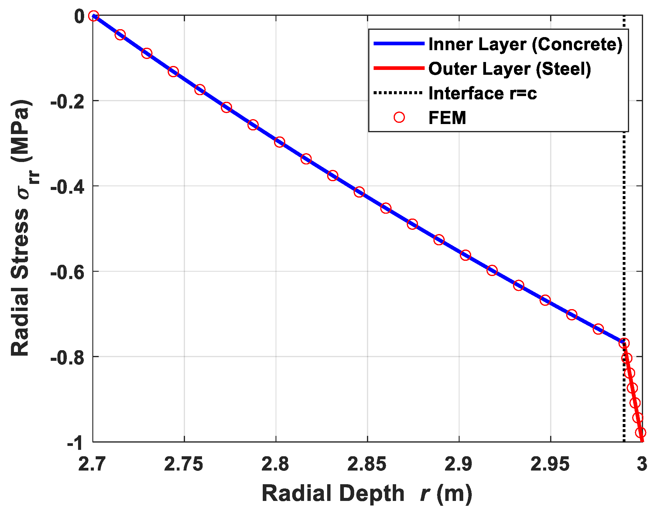
Figure 4 shows the comparison of radial stress distributions obtained from the analytical solution and the finite element model. The radial stress increases in magnitude from approximately zero at the inner boundary to −1.0 MPa at the outer boundary. The analytical curve and the FEM results agree well in both the concrete and steel layers. The radial stress is continuous across the interface, which is consistent with the perfect-bond interface condition and the radial equilibrium requirement. The steeper variation in radial stress in the thin outer steel layer is caused by the small steel-layer thickness and the relatively high stiffness contrast.
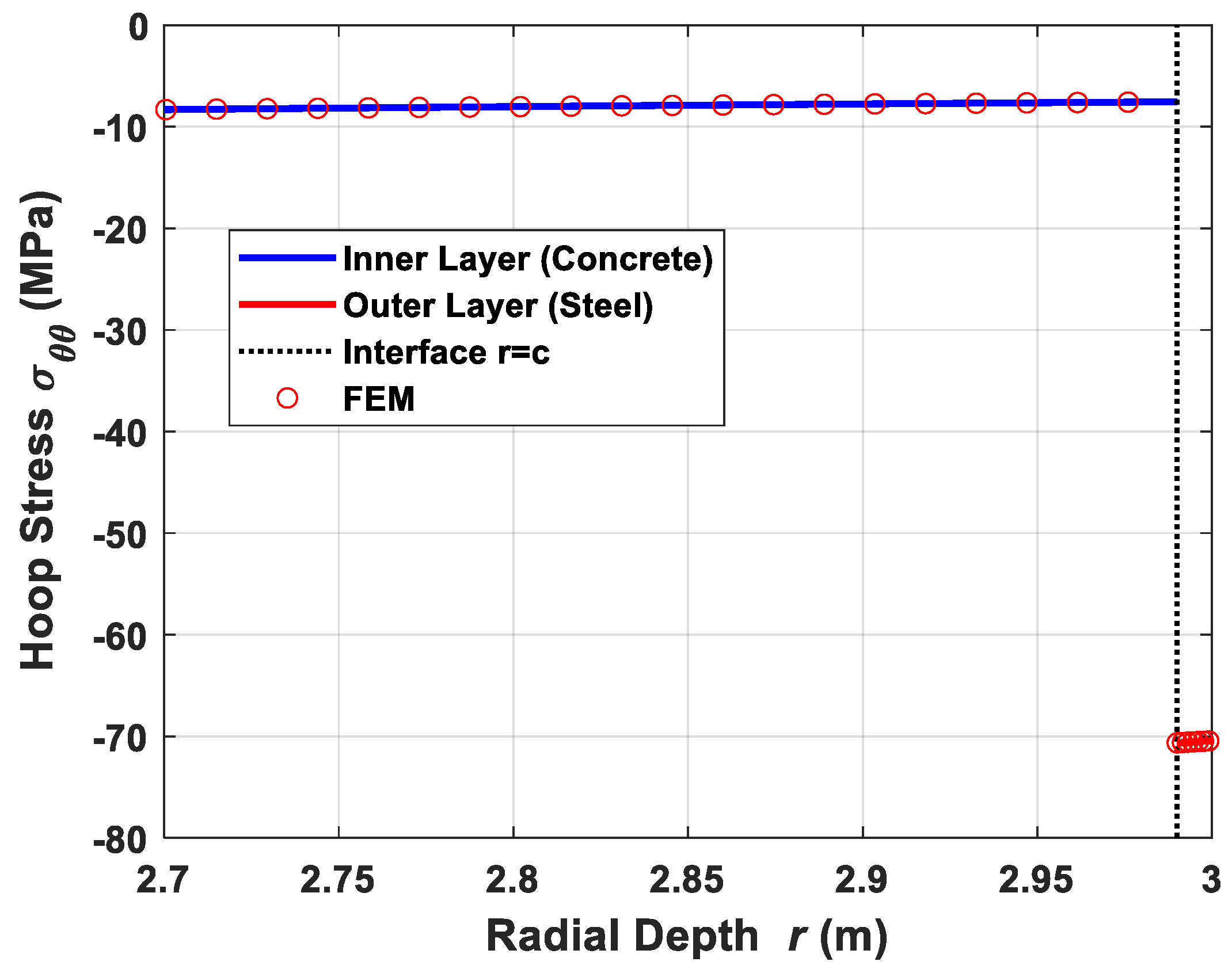
Figure 5 presents the corresponding hoop stress distributions. Compared with the radial stress, the hoop stress exhibits a clear discontinuity at the steel–concrete interface. The hoop stress in the concrete layer remains at a relatively low compressive level, whereas the hoop stress in the outer corrugated steel layer is much larger. This jump is caused by the difference in material stiffness between the isotropic concrete layer and the equivalent orthotropic steel layer. It does not violate the perfect-bond assumption because the continuity conditions at the interface require displacement and traction continuity, while the hoop stress is not required to be continuous across two dissimilar materials.
The FEM results closely follow the analytical solution in both layers, including the stress variation in the concrete layer, the sharp stress redistribution near the interface, and the high hoop stress in the corrugated steel layer. This agreement confirms that the proposed analytical solution can accurately capture the axisymmetric response of the two-layer composite lining and the stress redistribution induced by material orthotropy and stiffness mismatch.
3.4. Validation Case V3: Two-Layer Composite Lining Under Non-Uniform Pressure
The third validation case was conducted to further verify the applicability of the proposed analytical solution under non-uniform external pressure. The same two-layer composite lining as in Case V2 was adopted, in which the inner layer was isotropic concrete, and the outer layer was equivalent cylindrically orthotropic corrugated steel. The inner radius, interface radius, and outer radius were a = 2.7 m, c = 2.99 m, and b = 3.0 m, respectively. Unlike the previous two axisymmetric cases, this case introduces a second-order harmonic pressure component, which breaks the purely axisymmetric response and generates an asymmetric stress field. Therefore, it is used to verify the asymmetric harmonic component of the proposed analytical solution.
Different from Cases V1 and V2, the external pressure in Case V3 was non-uniform and was expressed as
where p
0b = 1.0 MPa and p
1b = 0.5 MPa. The inner boundary was traction-free, and no tangential traction was applied on the outer boundary. This loading condition leads to a non-axisymmetric response of the composite lining. Therefore, a two-dimensional plane-strain finite element model with four-node quadrilateral elements was established for comparison with the analytical solution. The steel–concrete interface was modeled by shared nodes, corresponding to the perfect-bond assumption used in the analytical model.
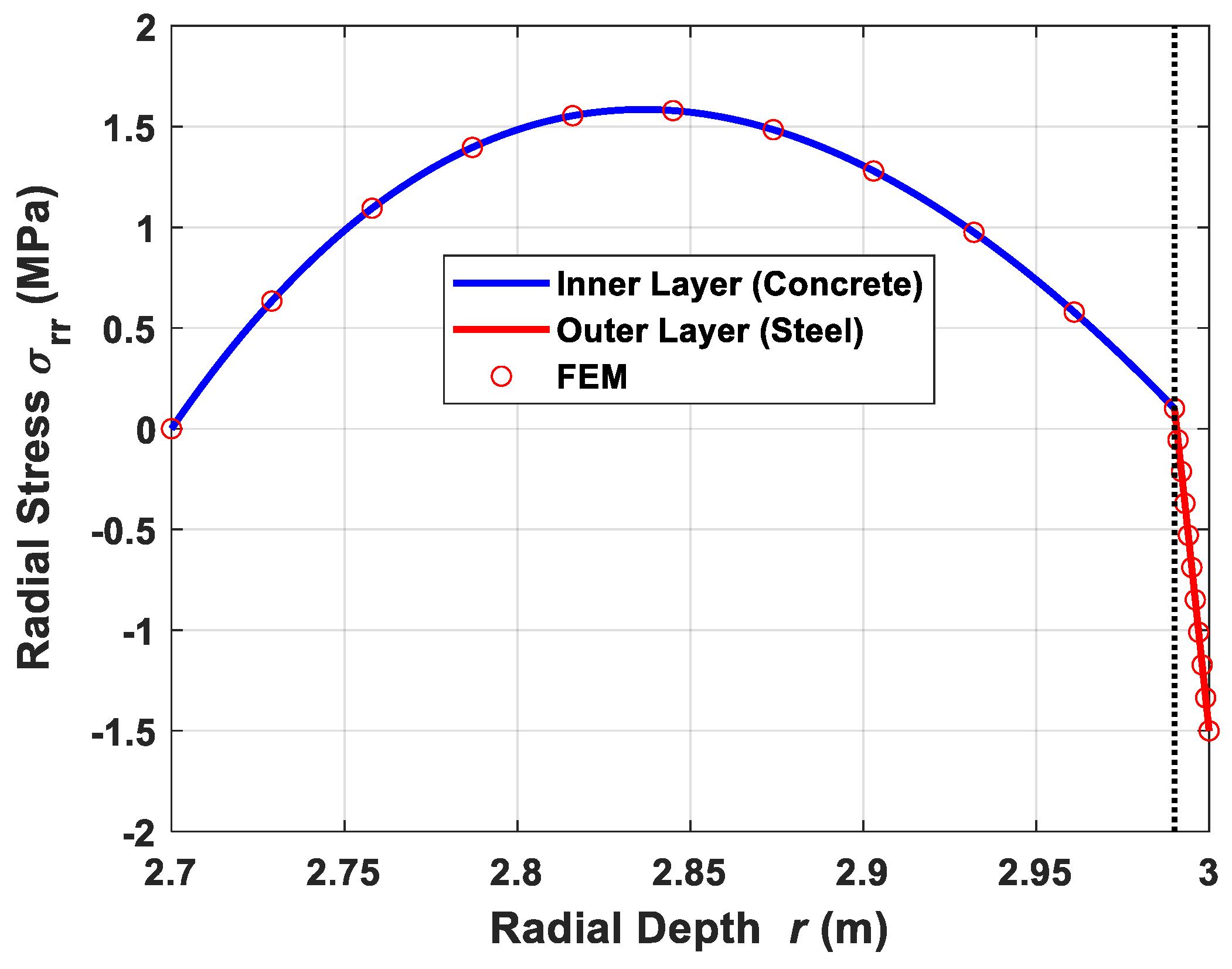
Figure 6 shows the radial stress distribution along the crown line (θ = 0°). Under the non-uniform external pressure, the radial stress no longer varies monotonically through the concrete layer. Instead, the radial stress first increases to a tensile value within the concrete layer and then decreases toward the steel–concrete interface. It should be noted that the present validation case is interpreted within the linear-elastic framework. If tensile stress appears in the concrete layer, the obtained value represents the elastic stress demand before cracking rather than the post-cracking stress state. Concrete cracking, stiffness degradation, and post-cracking stress redistribution are not considered in the present analytical formulation. Therefore, when the tensile stress exceeds the tensile strength of concrete, nonlinear cracking analysis or detailed numerical modeling would be required. In the thin outer corrugated steel layer, the radial stress changes rapidly and reaches the prescribed external boundary value. At the crown, the external pressure is
and the FEM result satisfies the boundary condition σ
rr(b,0) = −1.5 MPa. The analytical and FEM results show good agreement over the entire radial range, indicating that the proposed solution can correctly capture the radial stress response caused by the second-order non-uniform pressure.
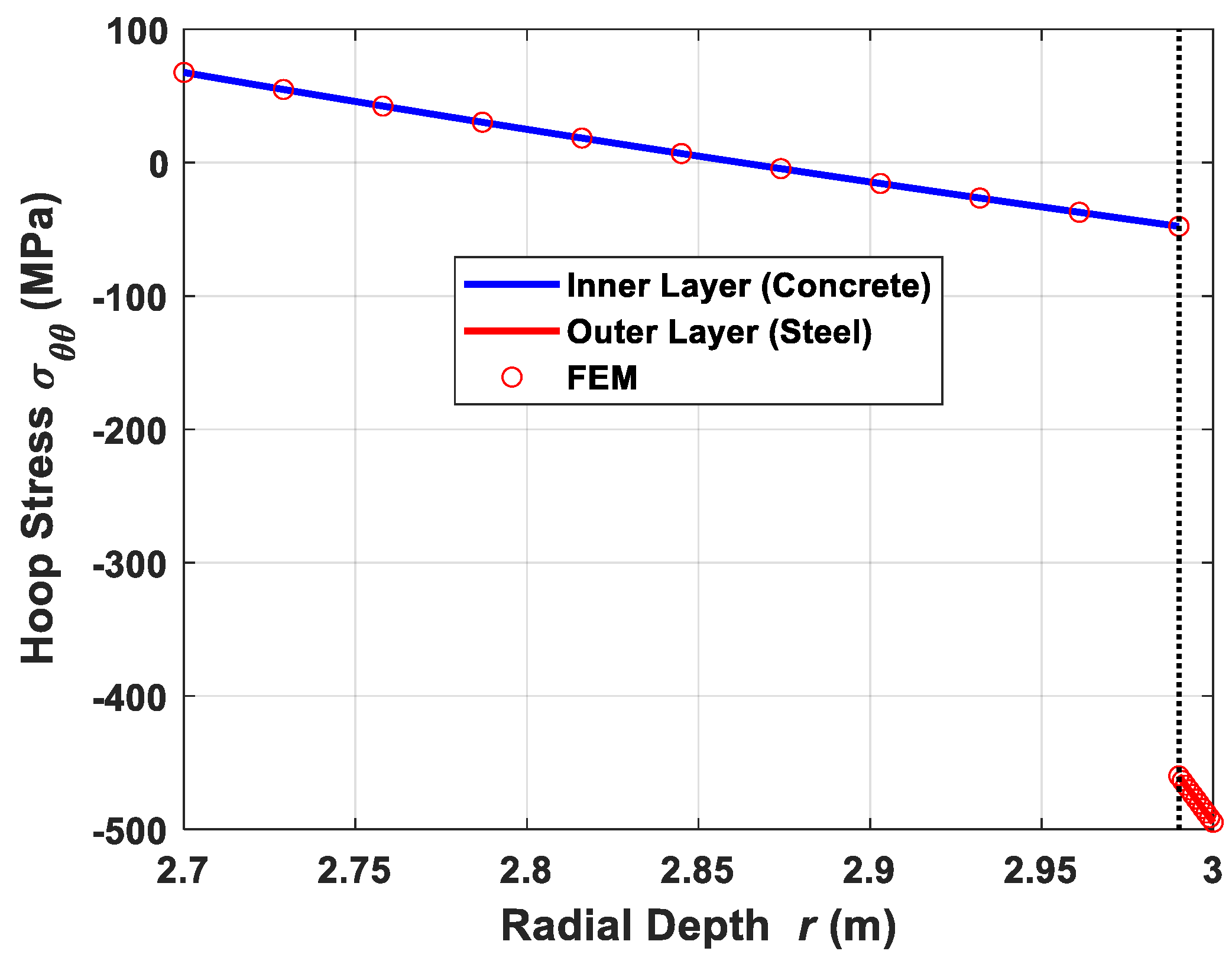
Figure 7 presents the hoop stress distribution along the same crown line. A significant difference can be observed between the concrete layer and the corrugated steel layer. In the concrete layer, the hoop stress changes gradually along the radial direction and varies from tensile to compressive values. In contrast, the outer corrugated steel layer carries a much larger compressive hoop stress. A clear stress jump occurs at the steel–concrete interface. This jump is caused by the stiffness mismatch between the isotropic concrete and the equivalent orthotropic corrugated steel. It does not contradict the perfect-bond assumption because perfect bonding requires the continuity of displacement and traction components, whereas the hoop stress is not required to be continuous across an interface between two different materials.
To further verify the robustness of the proposed solution at different angular positions, additional comparisons were conducted for Case V3.
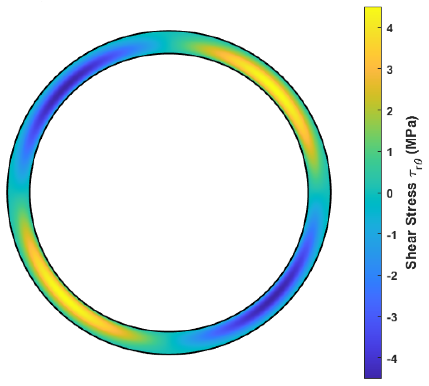
Figure 8 presents the FEM contour of shear stress
under non-uniform external pressure. The shear stress shows a clear asymmetric distribution induced by the second-order harmonic pressure component.
Figure 9 and
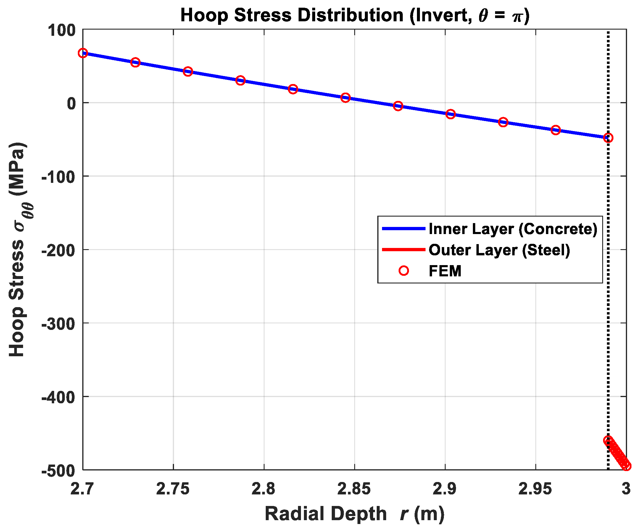
Figure 10 compare the hoop stress
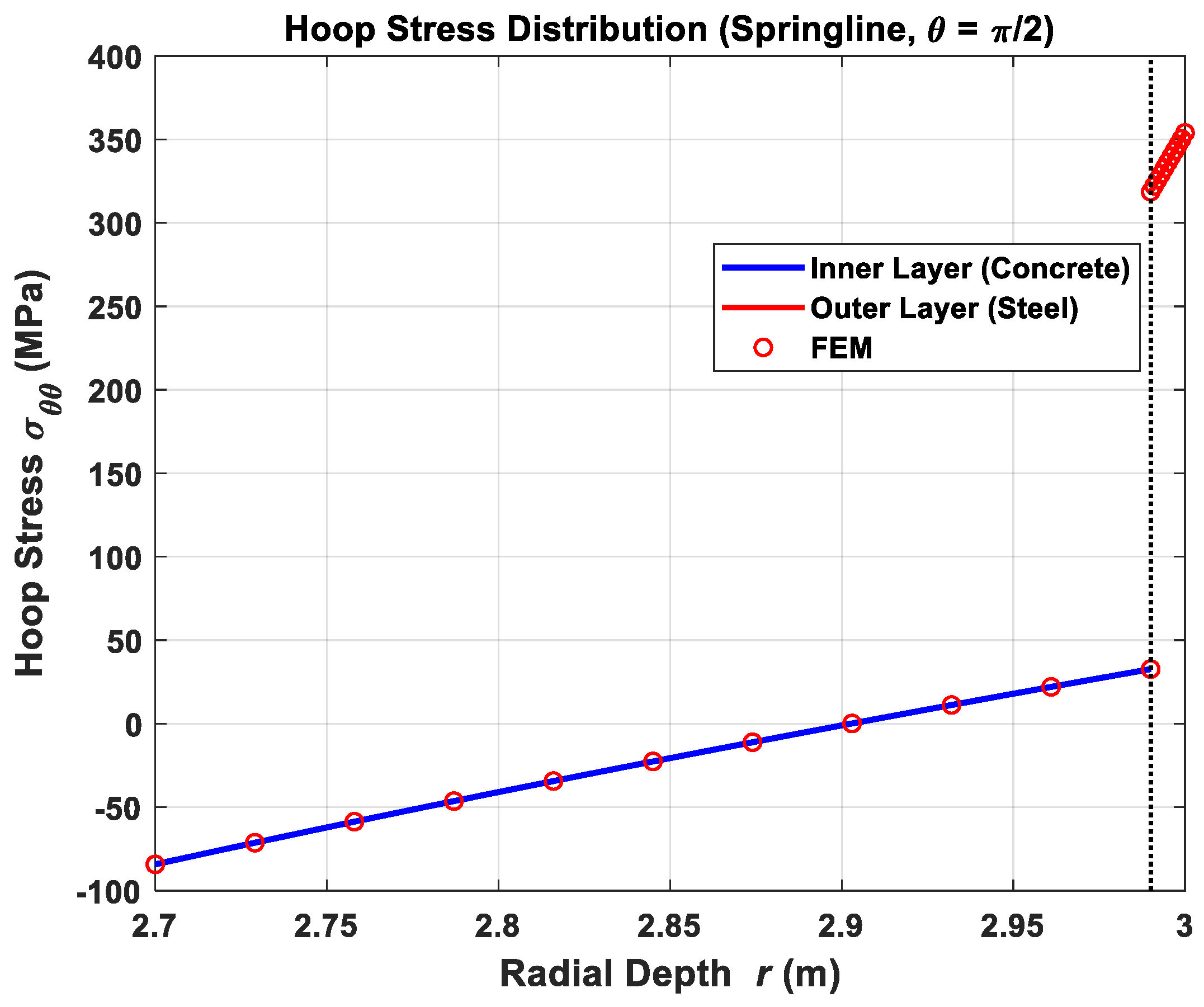
distributions along the springline
and the invert line
, respectively. The analytical results agree well with the FEM results at both angular positions. At the springline, the corrugated steel layer carries a large tensile hoop stress near the outer boundary, whereas at the invert line, it carries a large compressive hoop stress. These results demonstrate that the proposed formulation can capture the asymmetric harmonic stress redistribution at different circumferential positions of the composite lining.
The stress discontinuity in at the steel–concrete interface results from the stiffness mismatch between the two layers and does not violate the perfect-bond assumption because displacement, radial stress, and shear stress remain continuous across the interface.
The FEM results are almost coincident with the analytical solution in both the concrete and steel layers. The agreement confirms that the proposed analytical solution can capture both the axisymmetric response under uniform external pressure and the asymmetric harmonic stress redistribution induced by tunnel-type non-uniform pressure. It should be noted that the FEM validation was conducted under the same constitutive assumptions, interface conditions, and boundary loading conditions as the analytical formulation. Therefore, the comparisons mainly confirm the mathematical consistency and implementation accuracy of the proposed solution within the adopted linear-elastic and perfect-bond framework. They should not be interpreted as a complete validation of the physical behavior of corrugated steel–concrete composite linings under all practical field conditions.
4. Results and Discussion
The verified analytical solution is further used to investigate the symmetry-related stress redistribution mechanism of corrugated steel–concrete composite tunnel linings. The following analysis focuses on the effects of layer arrangement, corrugated steel stiffness ratio, and burial depth. Particular attention is paid to how the axisymmetric component and the asymmetric harmonic component are redistributed between the concrete layer and the corrugated steel layer.
4.1. Calculation Parameters and Equivalent External Pressure
In this section, the proposed analytical solution is used to investigate the mechanical response of corrugated steel–concrete composite tunnel linings under external ground pressure. Unless otherwise specified, the geometric, material, and loading parameters listed in
Table 2,
Table 3,
Table 4 and
Table 5 are adopted as the reference case. The purpose of this section is not to reproduce the full soil–structure interaction process, but to evaluate the stress redistribution and deformation response of the composite lining under an equivalent tunnel external pressure.
The inner and outer radii of the composite lining are taken as a = 2.700 m and b = 3.0 m, respectively. The total lining thickness is therefore 0.300 m. The thickness of the corrugated steel layer is ts = 0.010 m, and the thickness of the concrete layer is tc = 0.290 m. Two-layer arrangements are considered in the following analysis. In Arrangement I, the corrugated steel layer is placed on the inner side, and the concrete layer is located outside. This arrangement represents a typical internal strengthening configuration for existing tunnels. In Arrangement II, the concrete layer is placed inside, and the corrugated steel layer is located outside. This arrangement represents a composite lining configuration in which the corrugated steel layer is closer to the external ground pressure.
Table 2.
Geometric parameters of the composite lining.
Table 2.
Geometric parameters of the composite lining.
| Parameter | Description | Value |
|---|
| a | Inner radius | 2.700 m |
| b | Outer radius | 3.000 m |
| ts | Corrugated steel layer thickness | 0.010 m |
| tc | Concrete layer thickness | 0.290 m |
| c | Interface radius | Depends on layer arrangement |
Table 3.
Definition of layer arrangements.
Table 3.
Definition of layer arrangements.
| Arrangement | Inner Layer | Outer Layer | Interface Radius |
|---|
| Arrangement I | Corrugated steel | Concrete | c = a + ts = 2.710 m |
| Arrangement II | Concrete | Corrugated steel | c = b − ts = 2.99 m |
The concrete layer is assumed to be isotropic, with an elastic modulus E
c = 32.5 GPa and Poisson’s ratio ν
c = 0.20. The corrugated steel layer is modeled as an equivalent cylindrically orthotropic material. The elastic modulus and Poisson’s ratio of the steel material are taken as E
s = 206 GPa and ν
s = 0.30, respectively. In the reference case, the circumferential-to-radial stiffness ratio of the corrugated steel layer is set as
and the longitudinal stiffness ratio is taken as
In
Section 4.3, α = 1 is used to represent an ordinary flat steel plate, while α > 1 represents corrugation-induced circumferential stiffness enhancement. The selected range of
is used to represent different levels of circumferential stiffness enhancement of the equivalent corrugated steel layer. It is intended for parametric investigation of the stress redistribution mechanism rather than for direct calibration of a specific corrugated steel profile. The longitudinal stiffness ratio
is kept constant in the parametric analysis because the present study mainly focuses on radial–circumferential stress redistribution and the influence of circumferential stiffness enhancement.
Table 4.
Material parameters used in the reference case.
Table 4.
Material parameters used in the reference case.
| Material | Parameter | Description | Value |
|---|
| Concrete | Ec | Elastic modulus | 32.5 GPa |
| Concrete | νc | Poisson’s ratio | 0.20 |
| Steel | Es | Elastic modulus of steel | 206 GPa |
| Steel | νs | Poisson’s ratio of steel | 0.30 |
| Corrugated steel | α | | 12 |
| Corrugated steel | ηz | | 0.10 |
The external ground action is simplified as an equivalent non-uniform normal pressure acting on the outer boundary of the lining. The tangential ground traction is neglected in the present analysis. This simplification allows the difference between the vertical and horizontal ground pressures to be represented while keeping the analytical formulation tractable. Therefore, the outer boundary conditions are expressed as
where compression is taken as negative in the stress boundary condition. The pressure distribution can also be written as
in which the uniform term
represents the average pressure level, and the second-order harmonic term
represents the non-uniformity caused by the difference between the vertical and horizontal pressures. This loading form corresponds to the typical ovalization-type asymmetric response of circular tunnel linings and is therefore suitable for examining the symmetry/asymmetry-based stress redistribution mechanism of the composite lining. Higher-order harmonic components may occur under complex geological conditions, localized loading, construction disturbances, or local ground–lining interaction effects, but they are not included in the present parametric analysis in order to keep the mechanical interpretation focused. The two coefficients are defined as
where P
v and P
h are the equivalent vertical and horizontal ground pressures, respectively. In the present coordinate system, θ = 0° corresponds to the tunnel crown, θ = 90° corresponds to the springline, and θ = 180° corresponds to the invert. Therefore,
This means that the equivalent pressure reaches the vertical ground pressure at the crown and invert, and the horizontal ground pressure at the springline. When Pv = Ph, the external pressure degenerates into a uniform pressure.
The vertical pressure is calculated as
and the horizontal pressure is calculated by considering the earth pressure at rest and the water pressure contribution:
where H is the burial depth, γ
s is the unit weight of soil, γ
w is the unit weight of water, and K
0 is the coefficient of earth pressure at rest. In the reference case,
where
φ = 26° is the internal friction angle of the soil.
Table 5.
Reference loading parameters.
Table 5.
Reference loading parameters.
| Parameter | Description | Value |
|---|
| H | Burial depth | 20 m |
| γs | Unit weight of soil | 18.6 kN/m3 |
| γw | Unit weight of water | 9.8 kN/m3 |
| φ | Internal friction angle | 26° |
| K0 | Earth pressure coefficient at rest | 1 − sin φ |
For the reference case, the calculated vertical and horizontal pressures are
and thus
The inner boundary of the lining is assumed to be traction-free.
It should be noted that the adopted external pressure is an equivalent boundary pressure rather than a complete soil–structure interaction model. Effects such as ground deformation compatibility, soil arching, construction unloading, interface friction between soil and lining, and non-axisymmetric geological conditions are not explicitly considered. This treatment is adopted to focus on the mechanical behavior of the corrugated steel–concrete composite lining and to enable a clear parametric investigation based on the analytical solution.
Based on the above reference conditions,
Section 4.2 compares the influence of layer arrangement,
Section 4.3 investigates the effect of the corrugated steel stiffness ratio, and
Section 4.4 further examines the influence of burial depth.
4.2. Effect of Layer Arrangement
The effect of layer arrangement is first investigated by comparing Arrangement I and Arrangement II. Although both arrangements retain the same circular geometry, changing the radial position of the equivalent orthotropic corrugated steel layer modifies the radial stiffness distribution and consequently changes how the axisymmetric and asymmetric harmonic stress components are redistributed between the concrete and steel layers. Arrangement I represents an inner corrugated steel strengthening configuration, in which the corrugated steel layer is placed near the tunnel clearance and the concrete layer is located outside. This arrangement corresponds to the common engineering practice of internal strengthening for existing tunnels. Arrangement II represents an outer corrugated steel composite lining, in which the concrete layer is placed inside, and the corrugated steel layer is located close to the external ground pressure. In the comparison, the total lining thickness, material parameters, steel thickness, and loading conditions were kept unchanged, and only the radial position of the corrugated steel layer was altered.
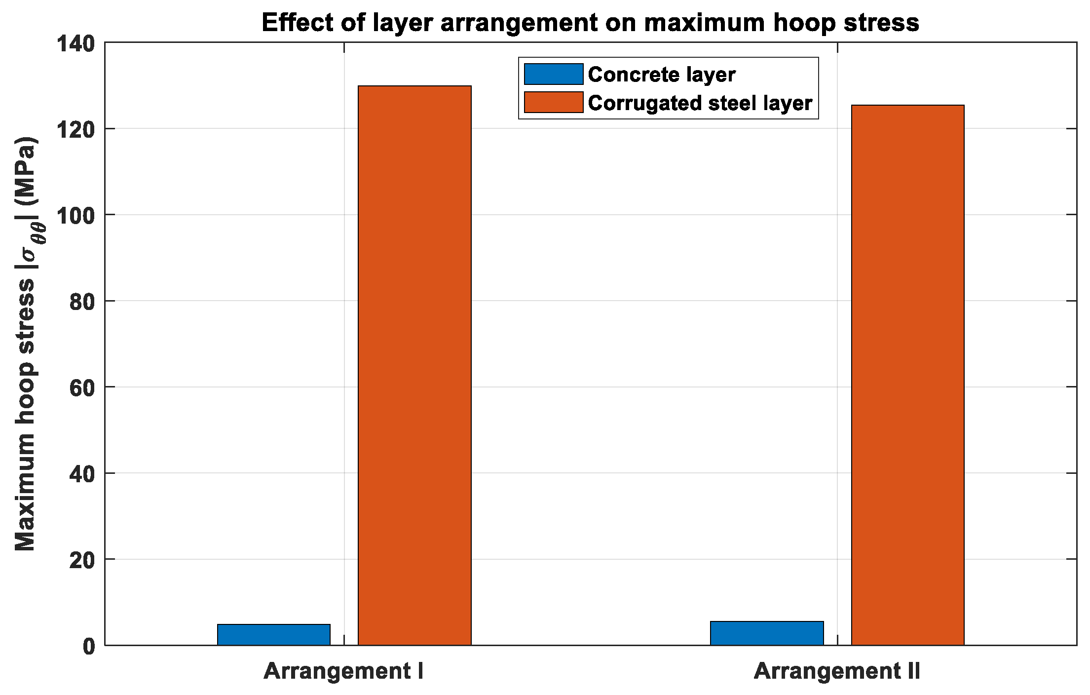
Figure 11 compares the maximum hoop stresses in the concrete and corrugated steel layers for the two arrangements. In both arrangements, the maximum hoop stress in the corrugated steel layer is much higher than that in the concrete layer. This result is expected because the corrugated steel layer has a much larger circumferential stiffness and is intended to carry a considerable portion of the circumferential load. Therefore, the relatively large stress in the steel layer should be interpreted as a load-sharing effect rather than as an unfavorable response. Compared with Arrangement II, Arrangement I produces a slightly larger maximum hoop stress in the steel layer, while the maximum hoop stress in the concrete layer remains low for both configurations. This indicates that both layer arrangements can mobilize the corrugated steel layer effectively, but the location where the load-sharing effect occurs is different.
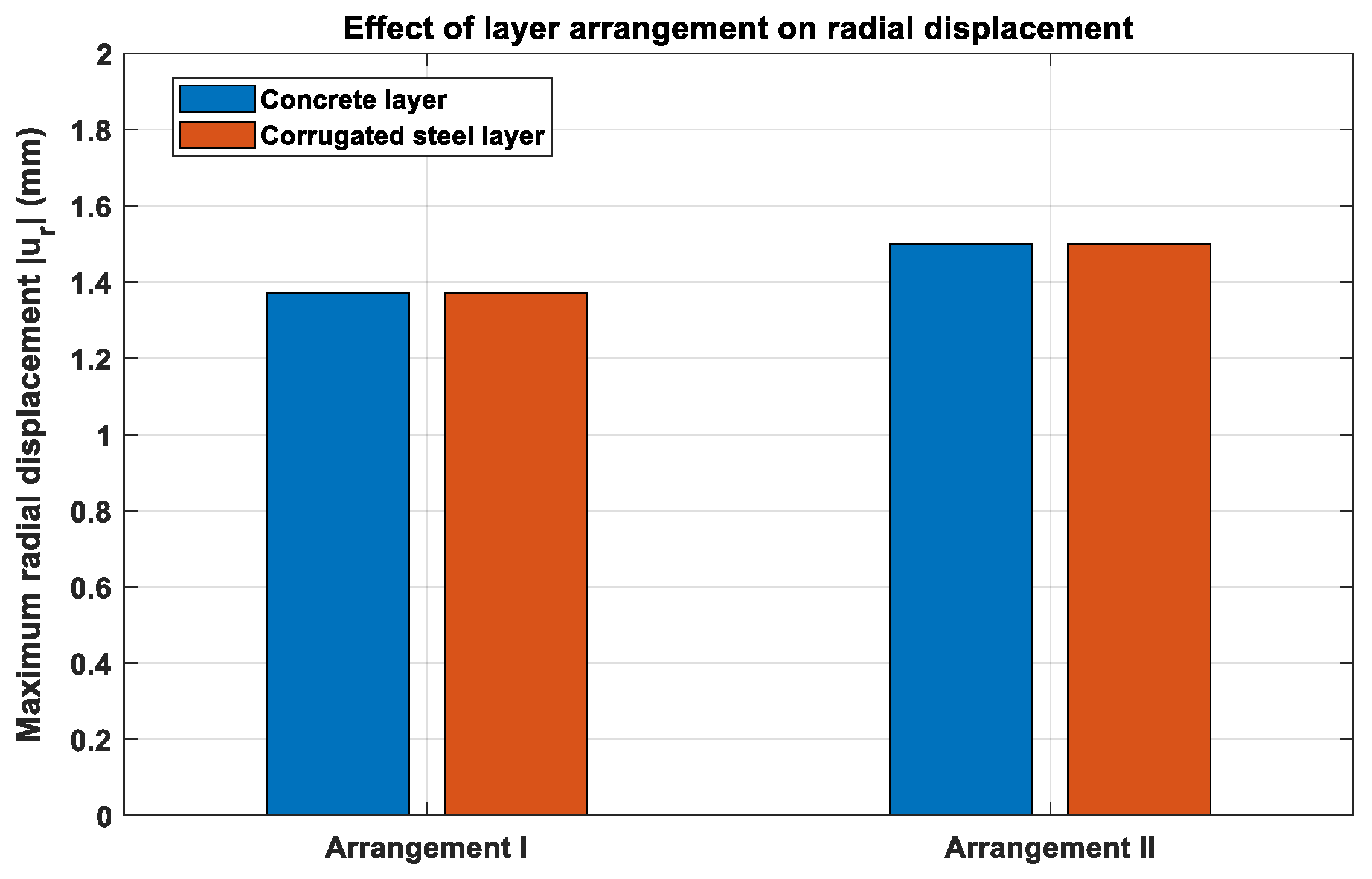
Figure 12 presents the maximum radial displacement of the two arrangements. The difference between the two configurations is relatively small compared with the difference in stress distribution. Arrangement II gives a slightly larger maximum radial displacement, whereas Arrangement I provides a slightly smaller displacement response. This suggests that changing the radial position of the steel layer has a more pronounced influence on stress redistribution than on the global radial deformation of the lining. In other words, the layer arrangement mainly changes how the circumferential stress is shared between the steel and concrete layers, while the overall deformation level remains comparable.
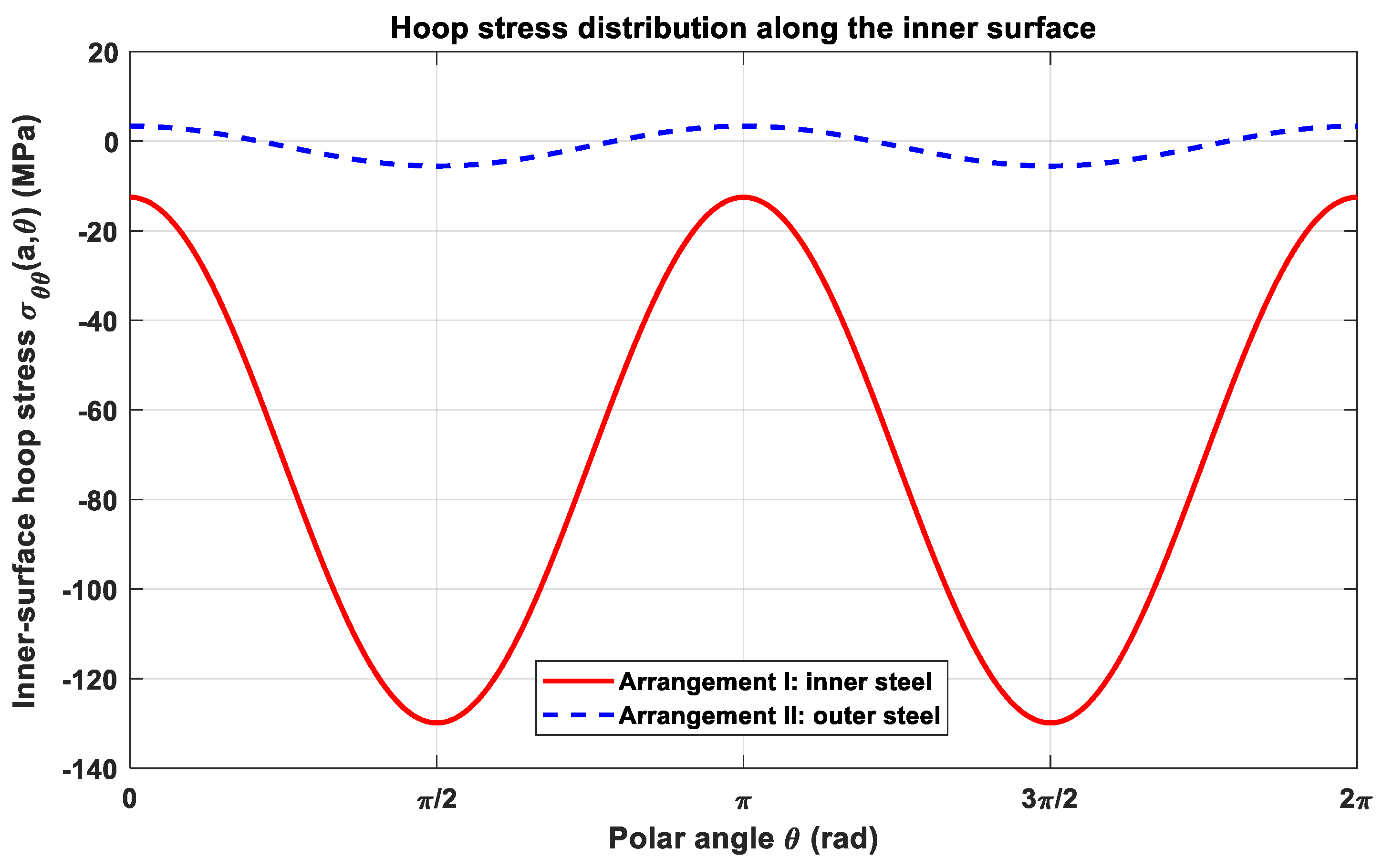
The hoop stress distribution along the inner surface is shown in
Figure 13. It should be noted that this figure is not a direct comparison of the same material because the inner surface belongs to the corrugated steel layer in Arrangement I but to the concrete layer in Arrangement II. Therefore, the result should be interpreted as the difference in inner-boundary response rather than a direct material-to-material comparison. For Arrangement I, the inner corrugated steel layer carries a large compressive hoop stress, which indicates that the steel layer directly participates in circumferential load resistance when it is installed at the tunnel clearance side. This behavior is consistent with its role as an internal strengthening component for existing tunnels. In contrast, the inner surface of Arrangement II is the concrete layer, and its hoop stress amplitude is much smaller. This indicates that, when the corrugated steel layer is placed outside, the inner concrete surface is less directly involved in carrying the external non-uniform pressure.
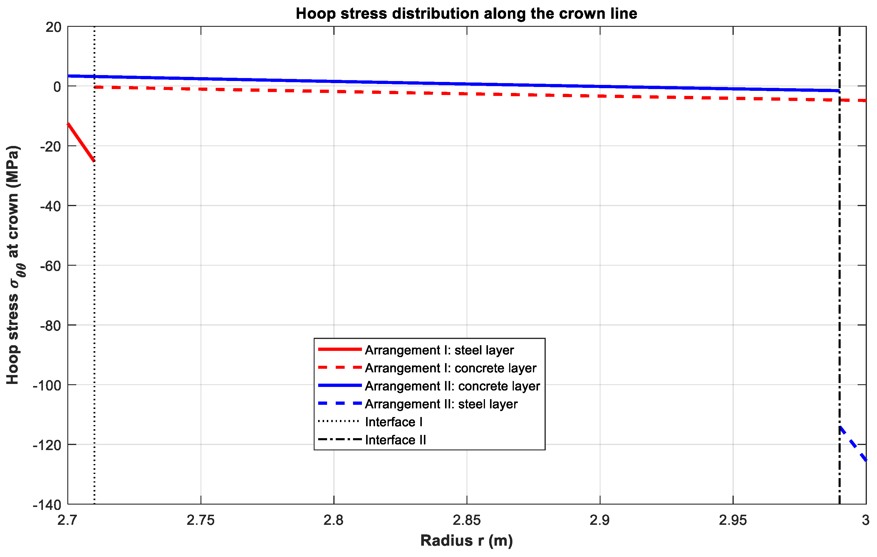
Figure 14 further shows the hoop stress distribution along the crown line. For Arrangement I, the corrugated steel layer is located near the inner boundary, and the stress jump appears at the interface close to r = a. For Arrangement II, the corrugated steel layer is located near the outer boundary, and the stress jump appears close to r = b. The discontinuity of hoop stress at the steel–concrete interface is caused by the stiffness mismatch between the two materials. This discontinuity does not violate the perfect-bond assumption because perfect bonding requires the continuity of displacement, radial stress, and shear stress, whereas the hoop stress is not required to be continuous across a material interface. The crown-line distributions further confirm that the corrugated steel layer carries a larger portion of the circumferential stress regardless of whether it is placed on the inner or outer side.
Overall, the comparison shows that the two arrangements have different engineering implications rather than a simple superiority relationship. Arrangement I is more suitable for internal strengthening of existing tunnels because the corrugated steel layer can be installed from the tunnel clearance side and directly contributes to the inner-side circumferential resistance. Arrangement II is more suitable for a new composite lining or a structure dominated by external ground pressure because the corrugated steel layer is placed closer to the external loading side and can participate more directly in resisting the external pressure. Therefore, the choice of layer arrangement should depend on the construction scenario and the target control index. If the objective is internal strengthening of an existing tunnel, Arrangement I has a clearer practical background. If the objective is to reduce the stress response of the inner concrete surface under external ground pressure, Arrangement II is more favorable.
The above comparison shows that the layer arrangement does not change the circular geometric symmetry of the lining, but it significantly affects how the axisymmetric and asymmetric harmonic stress components are redistributed between the concrete and steel layers. Therefore, the following stiffness-ratio analysis focuses on the outer corrugated steel arrangement as a representative configuration for studying the effect of corrugation-induced circumferential stiffness. This setting allows the influence of the stiffness ratio to be examined when the steel layer is directly adjacent to the external ground pressure.
4.3. Comparison with Ordinary Steel Plate and Effect of Corrugated Stiffness Ratio
The effect of corrugation-induced orthotropic stiffness enhancement was further investigated by varying the circumferential-to-radial modulus ratio of the steel layer. This stiffness ratio controls how the axisymmetric and asymmetric harmonic stress components are redistributed between the corrugated steel layer and the concrete layer.
where α = 1 represents an ordinary flat steel plate–concrete composite lining, while α > 1 represents corrugated steel layers with enhanced circumferential stiffness. In this section, α = 1, 4, 8, 12, and 16 were considered. The remaining geometric, material, and loading parameters were kept unchanged.
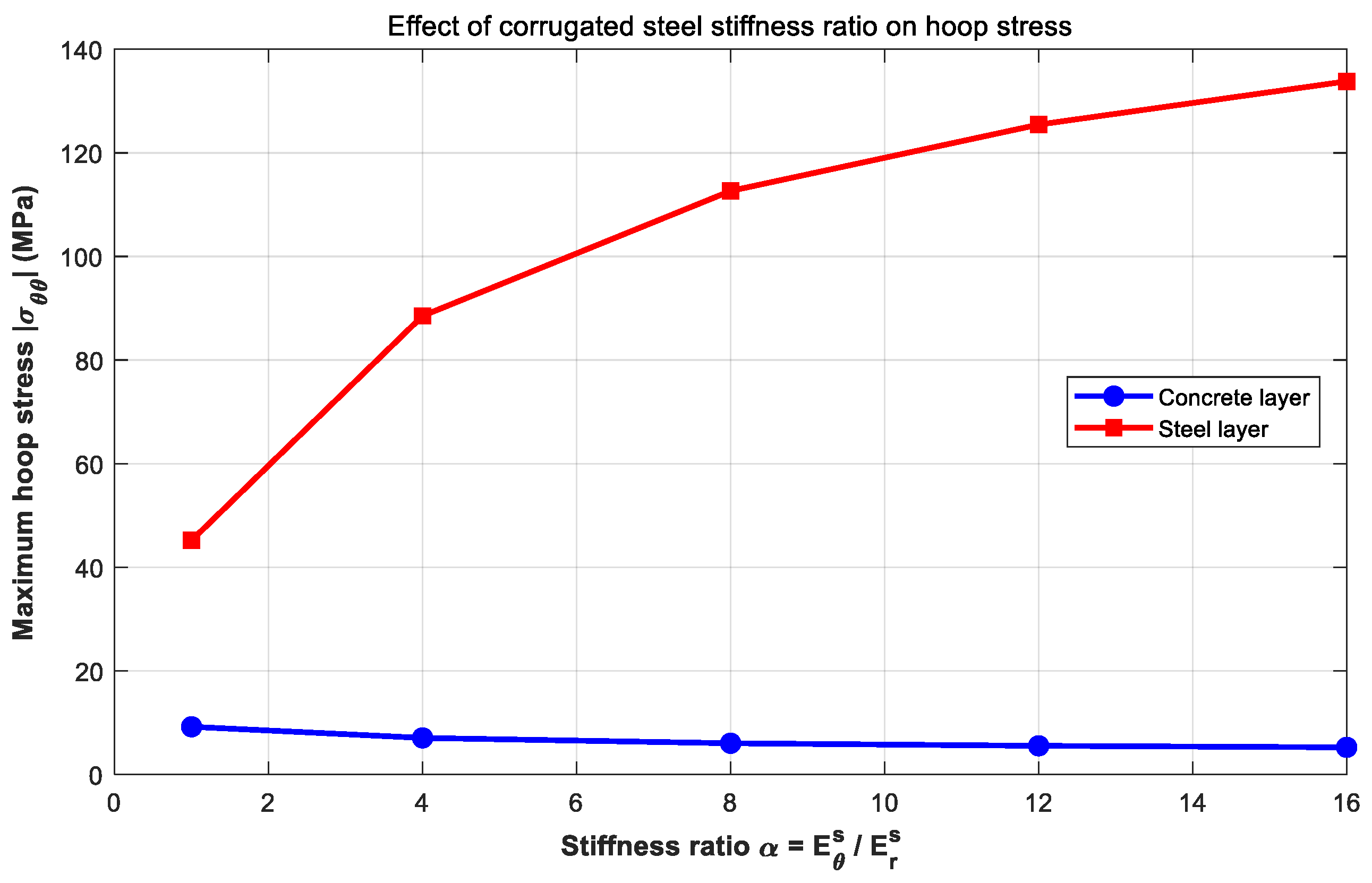
Figure 15 shows the maximum hoop stresses in the concrete and steel layers under different stiffness ratios. When α increases from 1 to 16, the maximum hoop stress in the concrete layer decreases gradually, whereas that in the steel layer increases significantly. For the ordinary steel plate case (α = 1), the maximum hoop stress in the steel layer is approximately 45 MPa. As α increases to 16, this value increases to about 135 MPa. In contrast, the maximum hoop stress in the concrete layer decreases from about 9 MPa to nearly 5 MPa. This indicates that the enhanced circumferential stiffness of the corrugated steel layer promotes stress transfer from the concrete layer to the steel layer, thereby reducing the stress demand in the concrete lining.
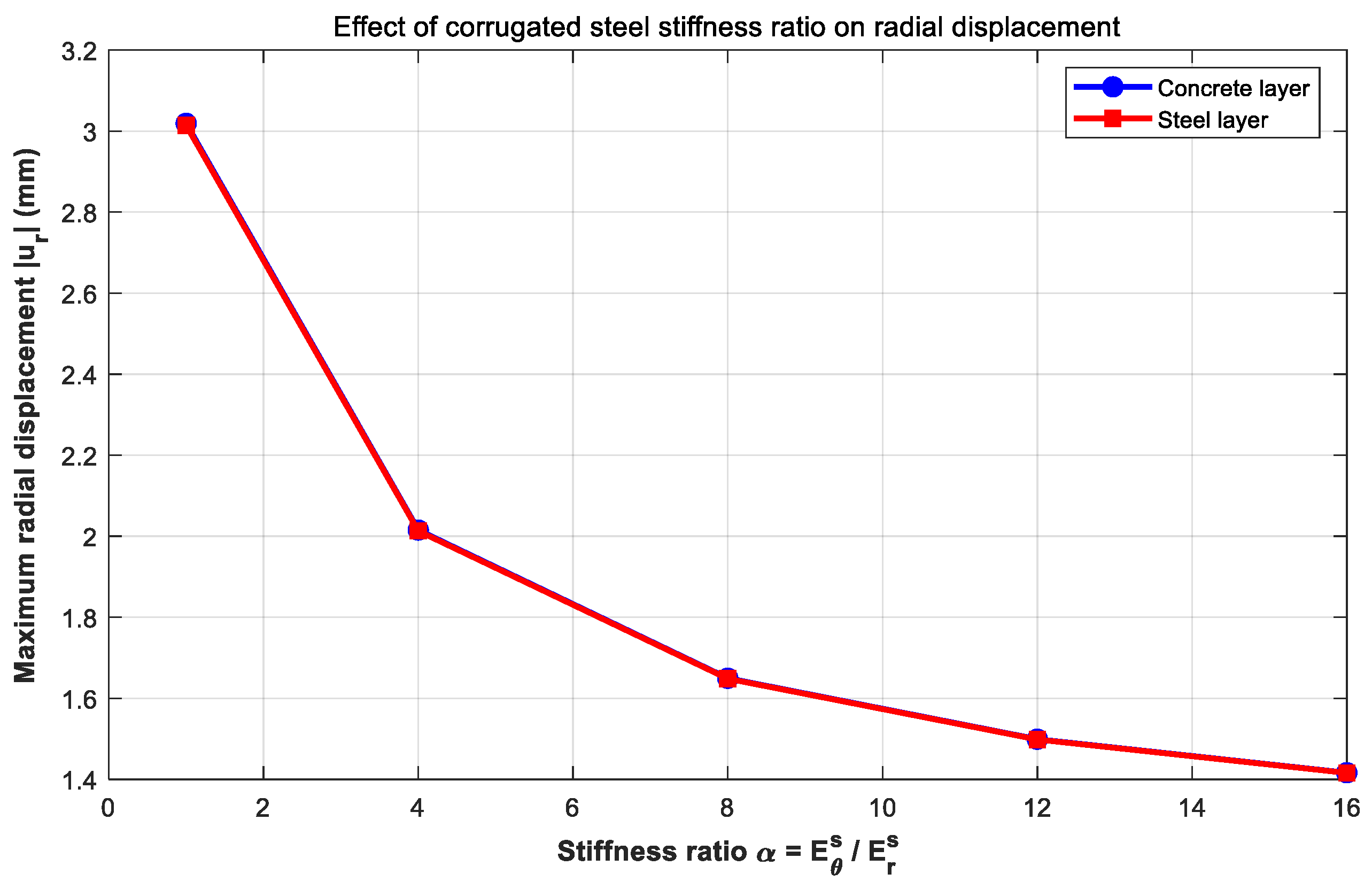
Figure 16 presents the variation in maximum radial displacement with α. The radial displacement decreases markedly as the corrugated stiffness ratio increases. The maximum radial displacement is about 3.0 mm for the ordinary steel plate case, while it decreases to approximately 1.4 mm when α = 16. This demonstrates that increasing the circumferential stiffness of the corrugated steel layer can effectively improve the deformation resistance of the composite lining. The reduction is more pronounced when α increases from 1 to 8, while the improvement becomes relatively moderate for larger stiffness ratios.
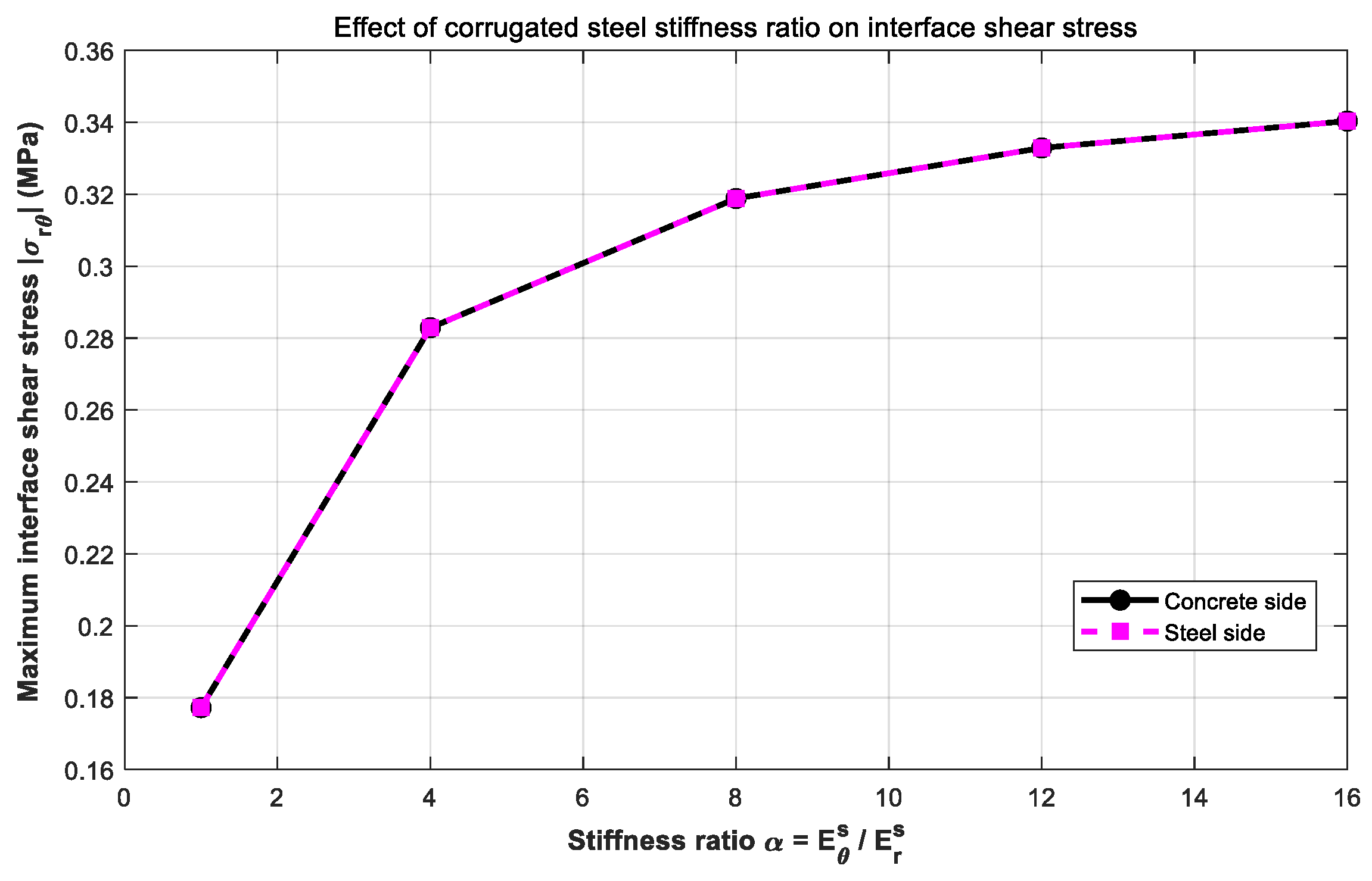
Figure 17 shows the variation in interface shear stress with the stiffness ratio. Although a perfect bond is assumed at the steel–concrete interface, the interface shear stress is reported here to quantify the shear transfer demand required to maintain composite action and displacement compatibility between the two layers. The interface shear stress increases with
, from approximately 0.18 MPa at
to about 0.34 MPa at
. The values obtained from the concrete side and the steel side almost coincide, confirming the continuity of shear traction at the perfectly bonded interface.
It should be emphasized that the calculated interface shear stress does not represent a direct evaluation of interface safety. In actual corrugated steel–concrete composite linings, the interface behavior may be affected by local slip, debonding, insufficient anchorage, construction defects, cyclic loading, and groundwater-induced deterioration. Therefore, the increase in interface shear stress with increasing stiffness ratio should be interpreted as an indicator of increasing interface demand rather than as evidence that the interface remains safe under all practical conditions. A detailed evaluation of interface damage or debonding requires an interface constitutive model or experimental calibration and is beyond the scope of the present linear-elastic analytical formulation.
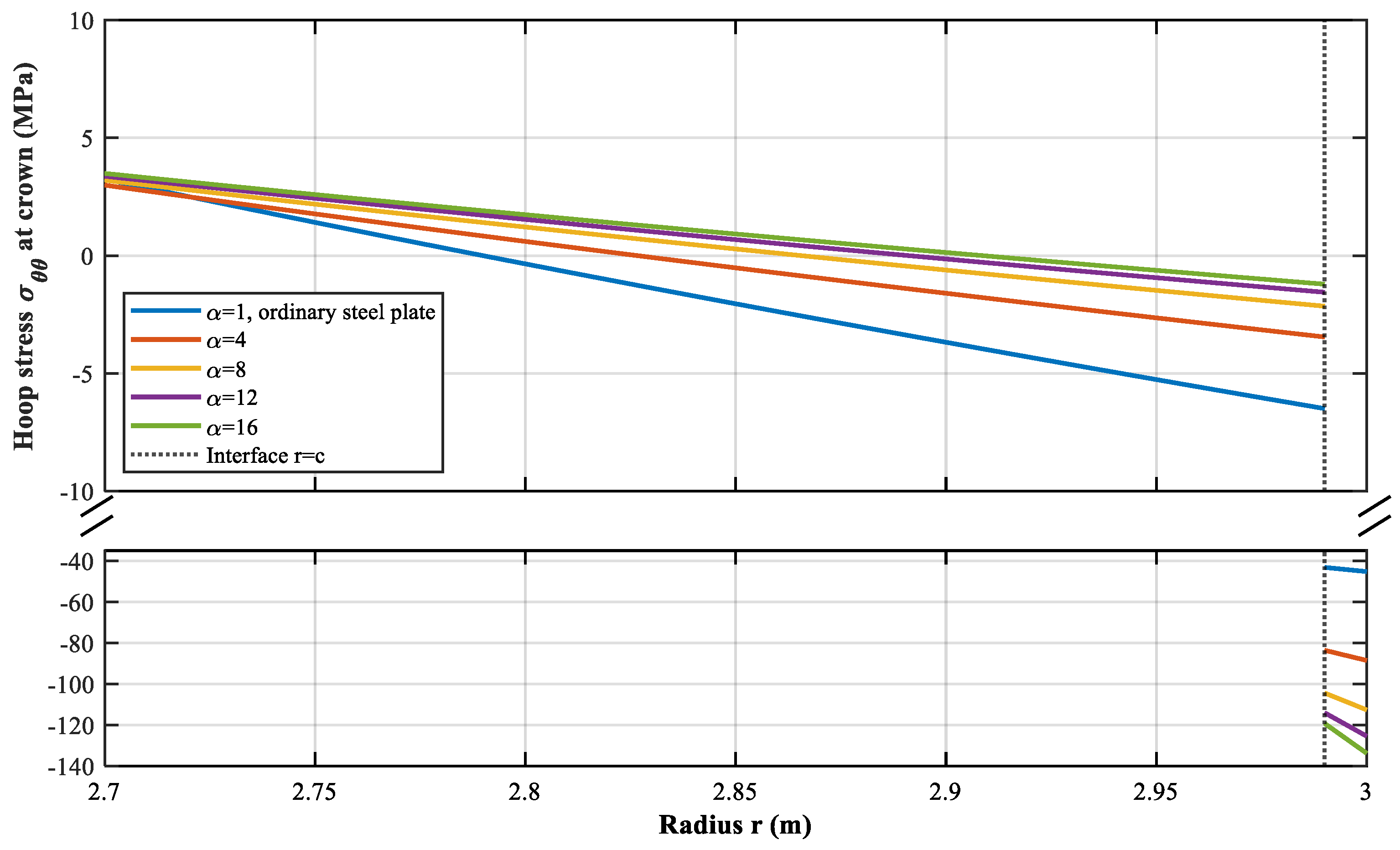
Figure 18 further illustrates the hoop stress distribution along the crown line (θ = 0°). A broken
y-axis is used to clearly display both the low-stress response in the concrete layer and the large compressive hoop stress in the corrugated steel layer. In the concrete layer, the hoop stress varies smoothly along the radial direction and decreases as α increases. At the steel–concrete interface, the hoop stress exhibits a clear jump, which is physically acceptable because the hoop stress is not required to be continuous across an interface between two different materials. In contrast, radial stress, shear stress, and displacement are continuous under the perfect-bond assumption. In the steel layer, the compressive hoop stress increases significantly with α, indicating that the corrugated steel layer carries a larger portion of the circumferential load. This confirms the stress redistribution mechanism observed in the maximum stress results.
Overall, compared with an ordinary steel plate–concrete composite lining, the corrugated steel layer with higher circumferential stiffness can reduce the hoop stress in the concrete layer and suppress the radial deformation of the lining. This indicates that increasing the orthotropic stiffness of the corrugated steel layer enhances its role in redistributing both the axisymmetric and asymmetric harmonic stress components. However, the increase in interface shear transfer demand should also be considered when designing the connection between the steel layer and the concrete layer. For the present parameter range, α = 8~12 provides a relatively effective improvement in stress redistribution and deformation control, while further increasing α leads to a more gradual improvement.
4.4. Effect of Burial Depth
To examine the influence of external pressure magnitude, the burial depth was varied while keeping the lining geometry, material parameters, layer arrangement, and lateral pressure coefficient unchanged. Since increasing burial depth changes the magnitude of the equivalent external pressure but does not change the harmonic form of the non-uniform pressure, this section mainly evaluates the response scaling under different external pressure levels. The outer corrugated steel arrangement, namely Arrangement II, was adopted as the representative configuration. Four burial depths were considered:
The corresponding vertical and horizontal pressures increase with H, and therefore both the uniform and non-uniform components of the external pressure increase proportionally.
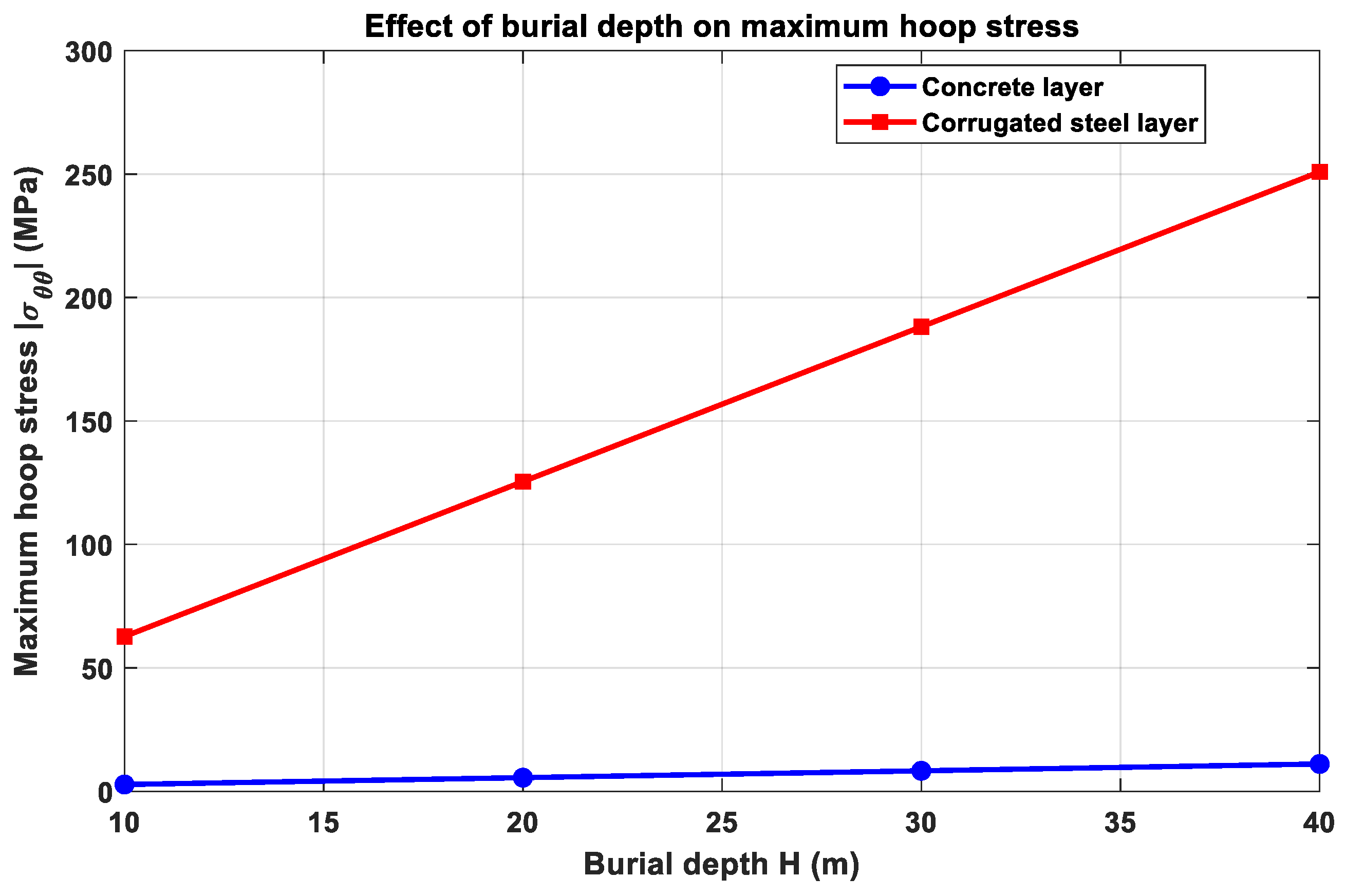
Figure 19 shows that the maximum hoop stresses in both the concrete and corrugated steel layers increase almost linearly with burial depth. The maximum hoop stress in the corrugated steel layer increases from about 63 MPa at H = 10 m to approximately 252 MPa at H = 40 m, while that in the concrete layer increases from about 3 MPa to about 12 MPa.
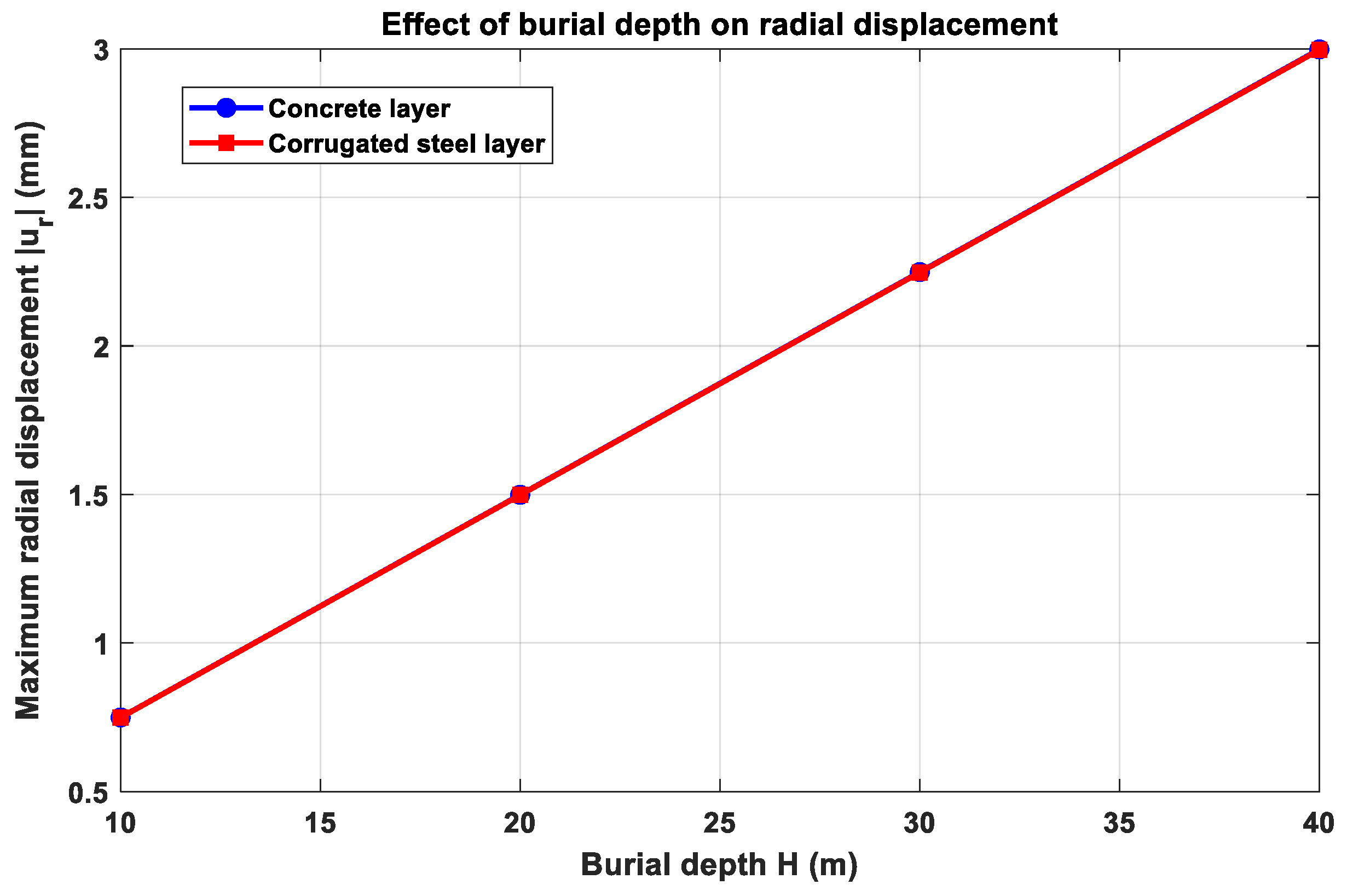
Figure 20 shows a similar trend for radial displacement, which increases from approximately 0.75 mm to about 3.0 mm over the same burial depth range. The nearly overlapping displacement curves of the two layers are consistent with the perfect-bond assumption at the steel–concrete interface.
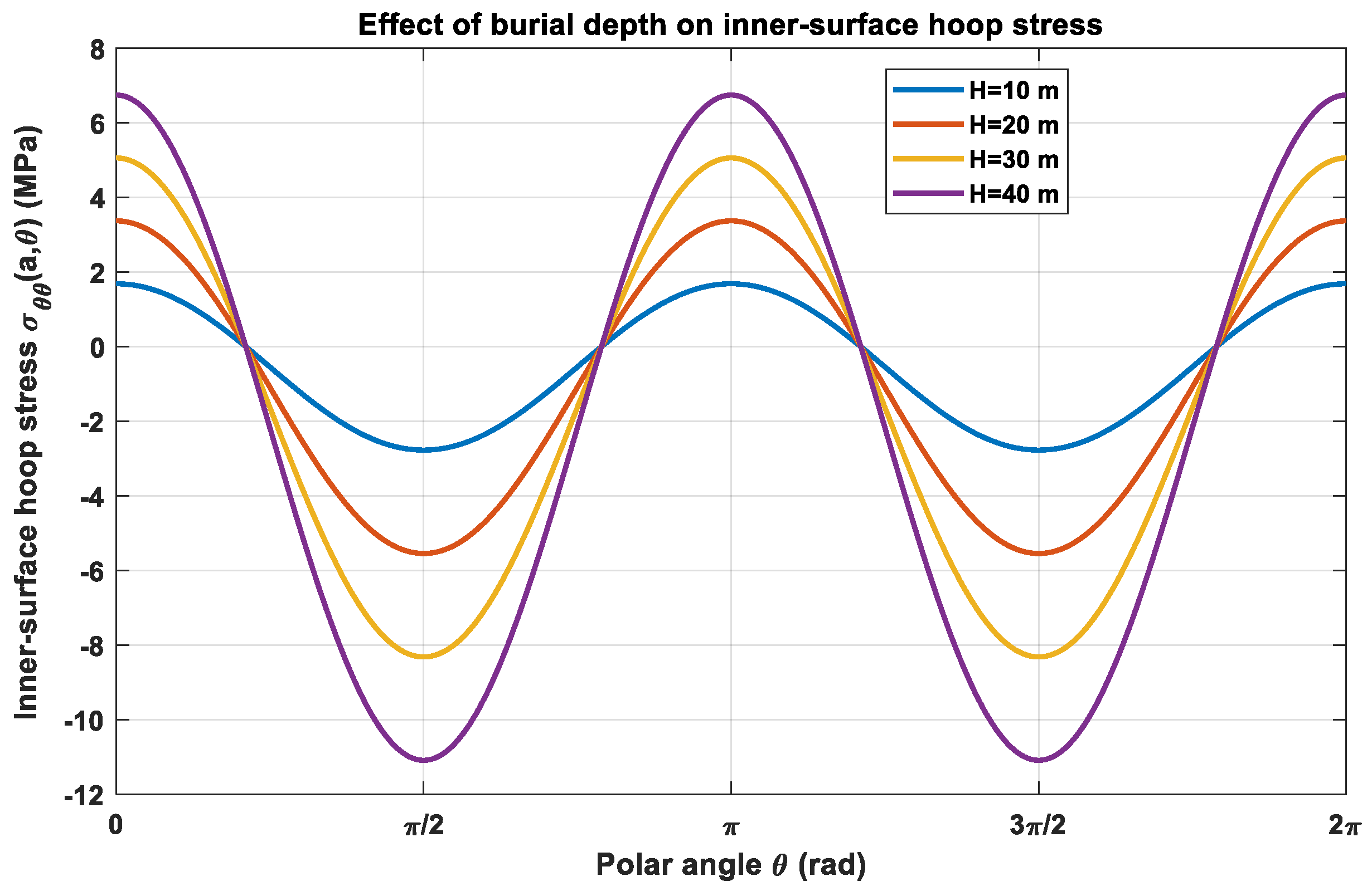
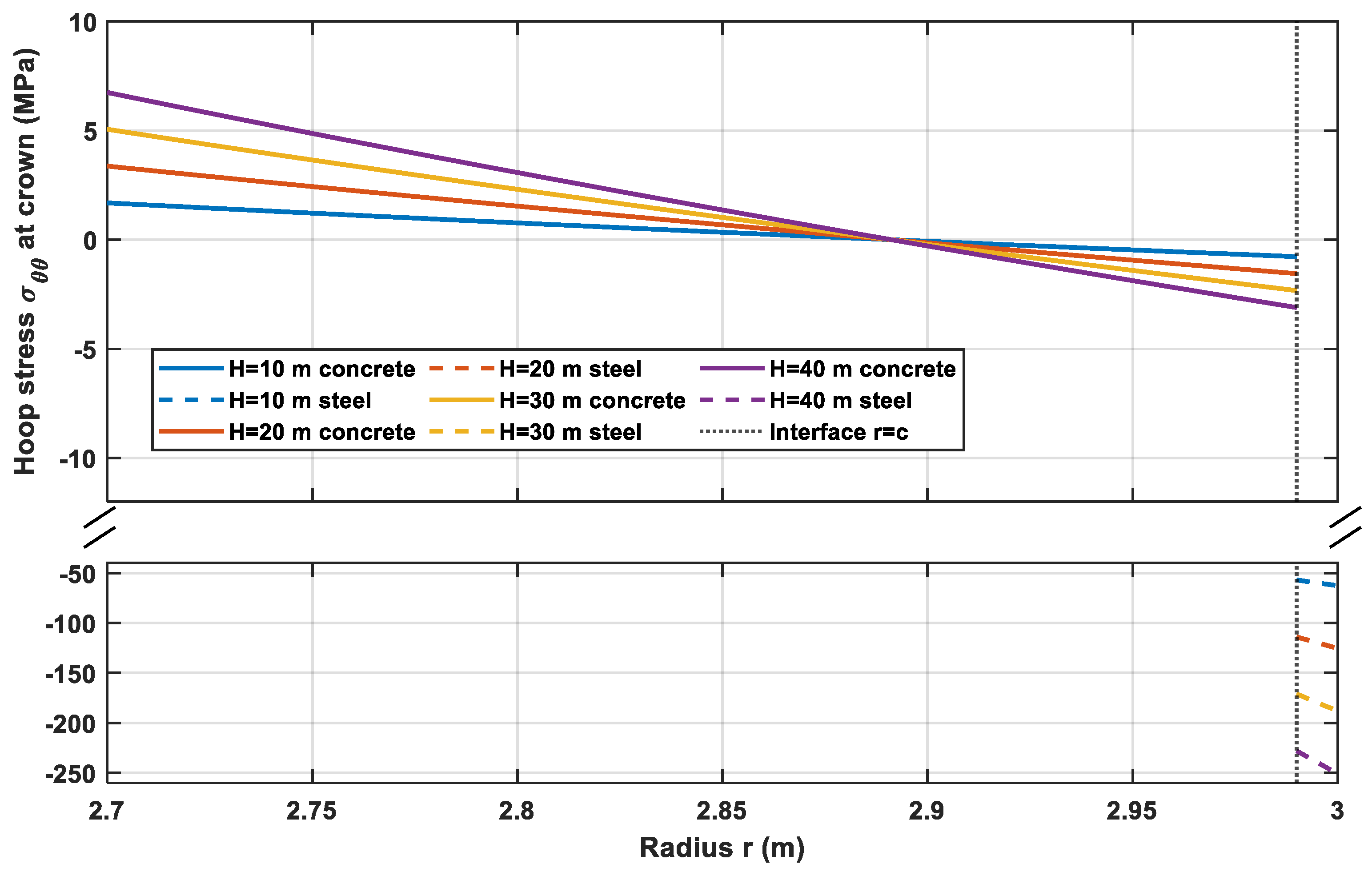
Figure 21 and
Figure 22 further show that increasing burial depth mainly amplifies the stress magnitude, while the angular and radial distribution patterns remain similar. Along the inner surface, the maximum tensile and compressive stresses appear at the same angular positions for different burial depths. Along the crown line, the concrete layer maintains a relatively low elastic stress level, whereas the corrugated steel layer carries much larger compressive hoop stress. The stress discontinuity at the steel–concrete interface is caused by the stiffness mismatch between the two layers and does not violate the perfect-bond assumption because displacement, radial stress, and shear stress remain continuous at the interface.
Overall, the burial depth analysis mainly reflects the amplification effect of external pressure magnitude under a fixed harmonic loading form. Therefore, it should be interpreted as a parametric check of response scaling under different external pressure levels rather than as a new stress redistribution mechanism. For deeply buried tunnels, the increased hoop stress in the corrugated steel layer and possible tensile stress in the concrete layer should be further evaluated with respect to material strength and nonlinear behavior.
4.5. Engineering Implications
The proposed symmetry-based decomposition provides a useful analytical benchmark for distinguishing the axisymmetric and asymmetric harmonic response mechanisms of corrugated steel–concrete composite tunnel linings. Based on the linear-elastic results obtained in the preceding sections, several implications can be drawn for the preliminary mechanical assessment and comparative analysis of corrugated steel–concrete composite linings.
First, the comparison of layer arrangements indicates that the radial position of the corrugated steel layer affects the elastic stress redistribution mechanism and should be considered together with the construction scenario and the target control index. When the corrugated steel layer is placed on the inner side, the configuration is more relevant to internal strengthening scenarios for existing tunnels because the steel layer can be installed from the tunnel clearance side. In this case, the inner corrugated steel layer directly participates in resisting circumferential deformation and carries a relatively large hoop stress. Therefore, this arrangement may provide a useful reference when the objective is to improve the elastic load-sharing contribution of an existing lining from the inside. In contrast, when the corrugated steel layer is placed on the outer side, the steel layer is closer to the external ground pressure. This arrangement can more directly mobilize the circumferential stiffness of the corrugated steel layer and reduce the elastic stress level of the inner concrete surface. Therefore, the outer corrugated steel arrangement may be more relevant to new composite linings or prefabricated composite tunnel structures in which the external ground pressure is the dominant action.
Second, the comparison with the ordinary steel plate indicates that the corrugated steel layer modifies the elastic stress redistribution of the composite lining. As the stiffness ratio increases, a larger portion of the hoop stress is transferred to the steel layer, while the elastic hoop stress and radial displacement of the concrete layer decrease within the investigated parameter range. This suggests that the circumferential stiffness enhancement induced by corrugation can contribute to elastic stress redistribution and deformation control. However, the improvement becomes less pronounced when is sufficiently large. Therefore, an excessively high corrugation-induced stiffness may not provide proportional additional benefit from the viewpoint of elastic structural efficiency.
Third, the burial depth analysis indicates that increasing the burial depth mainly amplifies the magnitude of stress and displacement responses without significantly changing the overall distribution pattern. Within the investigated burial depth range and loading form, the corrugated steel layer consistently carries the dominant hoop stress, while the concrete layer remains at a relatively low elastic stress level. This indicates a consistent elastic stress redistribution pattern under different external pressure levels. Nevertheless, for deeply buried tunnels, the increased hoop stress in the corrugated steel layer should be checked against the allowable stress or yield strength of the steel material.
It should also be emphasized that these implications are obtained under the assumptions of linear elasticity, equivalent external pressure, and perfect bonding at the steel–concrete interface. The calculated interface shear stress represents the shear transfer demand required to maintain composite action, rather than a direct evaluation of interface safety. In practical engineering, the composite action between corrugated steel and concrete depends on the interface connection, including bonding, anchorage, bolts, shear connectors, and grouting quality. Therefore, adequate connection detailing is required if the assumed composite action is to be achieved in practice.
Overall, the analytical results provide preliminary mechanical insights into two possible corrugated steel–concrete composite lining configurations. The inner corrugated steel arrangement may be more relevant to tunnel rehabilitation, whereas the outer corrugated steel arrangement may be more relevant to newly constructed composite linings dominated by external ground pressure. The proposed analytical solution can serve as a simplified benchmark for preliminary mechanical assessment and comparative analysis before detailed numerical modeling or project-specific design verification.
4.6. Limitations and Applicability
Several limitations of the present study should be noted. First, the proposed formulation is based on linear elasticity. Therefore, concrete cracking, steel yielding, stiffness degradation, and post-cracking stress redistribution are not considered. When tensile stress appears in the concrete layer, the obtained value should be interpreted as the elastic stress demand before cracking rather than the post-cracking stress state. If the tensile stress exceeds the tensile strength of concrete, nonlinear cracking analysis, cracking-resistance evaluation, or detailed numerical modeling would be required [
26]. Therefore, the results should not be interpreted as an evaluation of ultimate structural capacity or post-failure performance.
Second, the steel–concrete interface is assumed to be perfectly bonded. Under this assumption, displacement and traction continuities are enforced at the interface, and the calculated interface shear stress represents the shear transfer demand required for composite action. In practical tunnel linings, however, local slip, debonding, insufficient anchorage, construction defects, cyclic loading, and groundwater-induced deterioration may reduce the interface shear transfer capacity and cause local stress concentration. Therefore, the interface shear stress obtained in this study should be regarded as an indicator of interface demand rather than a direct evaluation of interface safety.
Third, the present solution is derived under the plane-strain assumption. It is therefore more suitable for tunnel sections where the geometry, material properties, and external pressure can be approximately regarded as uniform or slowly varying along the tunnel axis. Tunnel regions close to portals, cross passages, construction joints, segmental joints, local defects, and strongly three-dimensional loading zones may exhibit significant longitudinal effects that are not captured by the present two-dimensional formulation. For such cases, three-dimensional numerical modeling or an extended analytical framework would be required.
In addition, the corrugated steel layer is represented as an equivalent cylindrically orthotropic continuum. The stiffness ratios and are used as parametric indicators in this study. For a specific corrugated steel profile, these equivalent stiffness parameters should be calibrated through unit-cell homogenization, mechanical testing, or detailed finite element modeling of the actual corrugation geometry. Therefore, the present results should be interpreted as a mechanistic and parametric assessment of corrugation-induced orthotropic stiffness rather than as a direct evaluation of a specific commercial corrugated steel product.
Finally, although the analytical formulation can accommodate general Fourier-type non-uniform pressure, the validation and parametric analyses mainly focus on the second-order cosine harmonic component as a representative tunnel-type non-uniform pressure mode. Higher-order harmonic components may exist in more complex ground–structure interaction conditions and should be considered in future extensions. Moreover, the FEM validation was conducted under the same linear-elastic constitutive assumptions, perfect-bond interface condition, plane-strain condition, and boundary loading assumptions as the analytical solution. Therefore, the comparisons mainly confirm the mathematical consistency and implementation accuracy of the proposed formulation, rather than representing a complete validation of the physical behavior of composite linings under all possible field conditions.