Article

Study on the Influence Factors of the Servo Steel Strut of Foundation Pit on Deflection Correction of Adjacent Shield Tunnel


1
Department of Civil Engineering, Hangzhou City University, Hangzhou 310015, China
2
College of Civil Engineering and Architecture, Zhejiang University, Hangzhou 310058, China
3
College of Civil Engineering, Zhejiang College of Construction, Hangzhou 311231, China
4
College of Civil Engineering, Zhejiang University of Technology, Hangzhou 310023, China
*
Author to whom correspondence should be addressed.
Symmetry 2026, 18(4), 645; https://doi.org/10.3390/sym18040645
Submission received: 5 March 2026 / Revised: 5 April 2026 / Accepted: 10 April 2026 / Published: 12 April 2026
(This article belongs to the Section Engineering and Materials)

Abstract

The deep foundation pit excavation of subway will cause horizontal displacement, uneven settlement and other adverse effects on the adjacent shield. The use of servo steel strut has a certain effect on deflection correction, but the current understanding of the influencing factors of deflection correction is not comprehensive. Based on structural and spatial symmetry, the influence of tunnel depth, tunnel and foundation pit clear distance and deformation control quantity of enclosure structure on deflection correction quantity was studied by symmetrically designed model test and numerical simulation, and the prediction formula of deflection correction quantity considering tunnel and foundation pit clear distance and deformation control quantity of enclosure structure was proposed. The results show that with an increase in the tunnel’s burial depth, deflection correction decreases significantly. When the tunnel is near the foundation pit bottom, there is no significant correction effect, and the control law of the tunnel ground pressure under the servo steel strut loading is consistent with the correction law. Deflection correction is negatively correlated with the tunnel and foundation pit clear distance, and positively correlated with the deformation control of the diaphragm wall. The curve of the deformation control of the enclosure structure and the deflection correction is parabolic. The deflection correction is an exponential function of the ratio of the deformation control of the enclosure structure to the clear distance between the tunnel and the foundation pit, and the servo deflection correction follows a normal distribution along the longitudinal axis of the tunnel, showing obvious symmetry characteristics in the foundation pit influence zone.

1. Introduction

Metro lines crisscross in urban areas of large cities, and new metro foundation pits are often adjacent to existing operational metro tunnels, making the metro construction environment increasingly complex. Excavation of deep metro foundation pits changes the stress state and deformation conditions of the ground soil [1,2], causing adverse effects such as horizontal displacement and unequal settlement of adjacent existing shield tunnels, and the problem of impact on the surrounding environment has become increasingly prominent [3,4,5]. Currently, control measures such as zoned excavation of foundation pits and the setting of isolating pile walls are mainly adopted, but given the increasingly stringent deformation control requirements [6,7,8], these measures have limitations, including a long construction period and an inability to achieve real-time active control. Therefore, studying the control of side tunnel deformation by servo steel struts has important engineering significance.
Current scholars mainly adopt methods such as numerical simulation, measured analysis, and theoretical analysis to study the control of side tunnel deformation by servo steel struts.
In terms of measured analysis, some scholars [9,10,11] found through analysis of measured data that the use of servo steel struts in deep metro foundation pits can make the deformation of metro tunnels meet harsh deformation control requirements. However, such studies are mostly based on a single specific engineering case, and the research conclusions are greatly affected by the geological conditions and design parameters of the project, lacking systematic quantitative research on the key influencing factors of deflection correction, and the universality of the conclusions is limited.
In terms of numerical simulation, some scholars [12,13,14] found through numerical simulations that servo loading can effectively control the lateral displacement of diaphragm walls, thereby controlling the displacement and deformation of adjacent metro tunnels. Lai et al. [15,16] developed an integrated framework combining in situ tests, three-dimensional finite element modeling and machine learning, and confirmed that the artificial neural network (ANN) model outperforms other algorithms in predicting deformation responses of deep excavations and adjacent tunnels, with higher accuracy than traditional empirical equations. However, most of these studies focus on the deformation control effect under specific working conditions, and do not systematically reveal the coupling influence of multiple key parameters, such as tunnel burial depth, pit–tunnel clear distance, and enclosure structure deformation control on deflection correction effect, which cannot provide targeted design guidance for engineering with different working conditions.
In terms of theoretical analysis: Huang et al. [17] derived the force balance equation of diaphragm walls using servo systems and found that excessive axial force of servo steel struts will lead to risks such as local force on retaining structures and tunnels. Zhu et al. [18] found through theoretical calculations that servo jacking has a great impact on adjacent shallow tunnels, and derived the distribution function of the servo deflection correction of adjacent tunnels. On this basis, Wang et al. [19] derived an empirical formula for adjacent strut axial force loss caused by servo steel strut loading based on model test and numerical simulation results, providing a theoretical tool for quantifying the impact of servo loading on the stress of structures around tunnels. However, the existing theoretical studies mostly focus on the mechanical response of the enclosure structure and the axial force of the struts, and lack a simple and practical prediction formula for the deflection correction that can be directly applied to engineering design, which limits the popularization and application of servo steel strut technology in engineering.
In terms of model tests, Chen et al. [20] analyzed the coordinated deformation law between the retractable internal support system and diaphragm walls through model tests, and found that extending the internal support can significantly control the horizontal displacement of diaphragm walls, but servo loading will cause a rapid increase in the axial force of internal supports. On this basis, Tang et al. [21] analyzed the mechanical characteristics of side tunnels during servo loading through indoor scaled model tests, and found that when the steel struts are loaded with expansion and contraction, the control of steel strut expansion and contraction at the bottom of the foundation pit on tunnel bending moment is greater than that of upper steel strut expansion and contraction, and the impact on soil pressure at the left and right hances is greater than that at the crown and invert. Wei et al. [22,23,24] carried out a series of scaled model tests and full-scale tests, revealing the influence of servo strut arrangement on the deformation control effect of diaphragm walls and tunnels. However, most of the existing model tests focus on the influence of the layout of servo steel struts, and lack systematic research on the influence of the spatial position relationship between the tunnel and the foundation pit (such as tunnel burial depth and pit–tunnel clear distance) on the deflection correction effect, which is the core concern in the design of actual engineering.
It can be found that current scholars mainly study the application effect of servo steel struts based on a specific engineering case, which does not reflect the influence of various factors, such as tunnel burial depth and clear distance between tunnel and foundation pit, on the servo deflection correction effect, and cannot provide targeted suggestions for engineering applications. In summary, the current research still has the following core limitations: (1) Most studies focus on the deformation control effect of servo steel struts in a single engineering case, lacking systematic quantitative research on the key influencing factors of servo deflection correction; (2) the influence of multi-factor coupling such as tunnel burial depth, pit–tunnel clear distance and enclosure structure deformation control on deflection correction effect is not clear; and (3) there is a lack of a simple and practical prediction formula for servo deflection correction that can be directly applied to engineering design. Therefore, it is necessary to carry out research on the influencing factors of active control of side tunnel deformation by servo steel struts. Horizontal displacement is the primary control index for adjacent operational shield tunnels. This study focuses on horizontal displacement correction in numerical simulations, while model tests verify the consistent variation laws of different deformation indicators. To fill the above research gaps, based on the similarity theory, this paper designs a scaled model test to study the influence of tunnel burial depth on the servo deflection correction. Numerical simulations are used to analyze the influence of factors such as the clear distance between the tunnel and the foundation pit and the deformation control of the diaphragm structure on the servo deflection correction effect. According to the analysis of influencing factors, a prediction formula and distribution function of servo deflection correction considering the clear distance between tunnel and foundation pit and the deformation control of diaphragm structure are proposed. This study can provide theoretical support and quantitative reference for the active deformation control of adjacent shield tunnels by servo steel struts in metro deep foundation pit engineering, and has important engineering application value.

2. Model Test

2.1. Design of Test Device and Material Parameters

The size of the model box used in the test is length × width × height = 2.5 m × 2.0 m × 1.5 m. Considering the influence of model box size and boundary effect [25], the geometric similarity ratio of this model test is selected as 1/25. Based on the similarity theorem and the Mohr–Coulomb failure criterion for geotechnical model tests, combined with the Froude number similarity criterion for soil mass deformation, the key similarity constants of the model test are designed and verified: the bulk density similarity ratio is taken as 1.0 (using homogeneous sand with the same bulk density as the prototype soil to ensure the consistency of soil stress–strain characteristics), the strain similarity ratio is 1.0 (strain is a dimensionless quantity, consistent between model and prototype), and the stress similarity ratio is equal to the geometric similarity ratio (derived from the stress–strain relationship of soil mass). The verification results show that the designed similarity constants satisfy the similarity condition of the geotechnical model test, and the mechanical response of the model can be converted to the prototype through the similarity ratio.
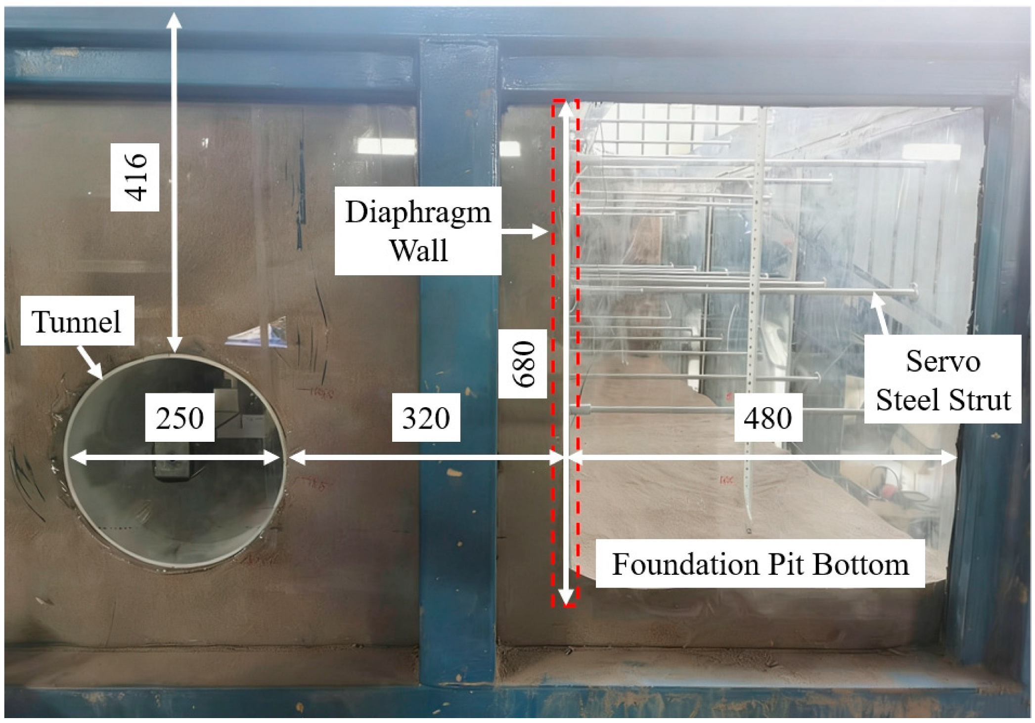
At present, most model tests carry out a similar design of diaphragm walls according to the principle of equivalent flexural stiffness [26]. In this paper, 6061 aluminum alloy plates are used to simulate a diaphragm wall. According to the equivalent calculation of flexural stiffness between the model and the prototype, the thickness of the aluminum plate is: length × height × thickness = 2000 mm × 1200 mm × 5 mm. The internal strut arrangement scheme is: 6 horizontal struts with a spacing of 320 mm, and 4 vertical layers with a spacing of 170 mm. Among them, the first layer adopts 6061 aluminum alloy rods to simulate concrete struts, and layers 2~4 adopt retractable aluminum rods to simulate servo steel struts. According to the principle of equivalent compressive stiffness [27], the outer diameter of the internal strut section is designed as 10 mm, and the inner diameter is 7 mm. The tunnel is simulated by grooved PVC pipes [27], and its size is designed according to the flexural stiffness similarity ratio: length × outer diameter × wall thickness = 2000 mm × 250 mm × 5 mm. The layout of the test device is shown in Figure 1. Using the symmetry of the foundation pit [28], it is simulated by a side-attached half-excavation, and the excavation size is length × width × depth = 2000 mm × 480 mm × 680 mm. Under the standard condition, the clear distance between the tunnel and the foundation pit is 320 mm, and the tunnel overburden thickness is 416 mm. Homogeneous sand is used to simulate the soil, and its physical and mechanical indicators and test material parameters are shown in Table 1. The above test devices include foundation pit, diaphragm wall, model tunnel, and servo steel struts, which have been systematically introduced and verified in our previous research [24].

2.2. Test Monitoring Plan

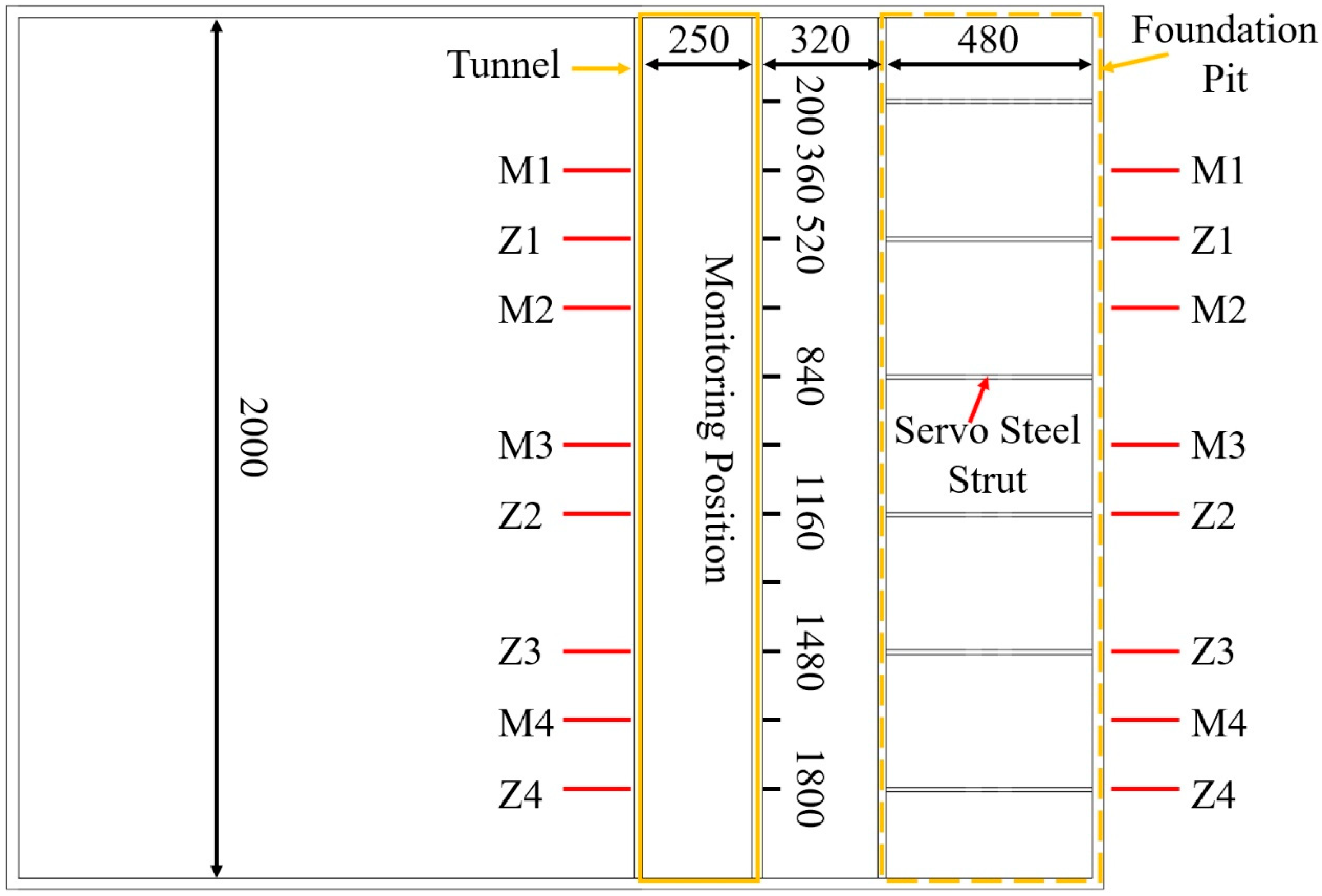
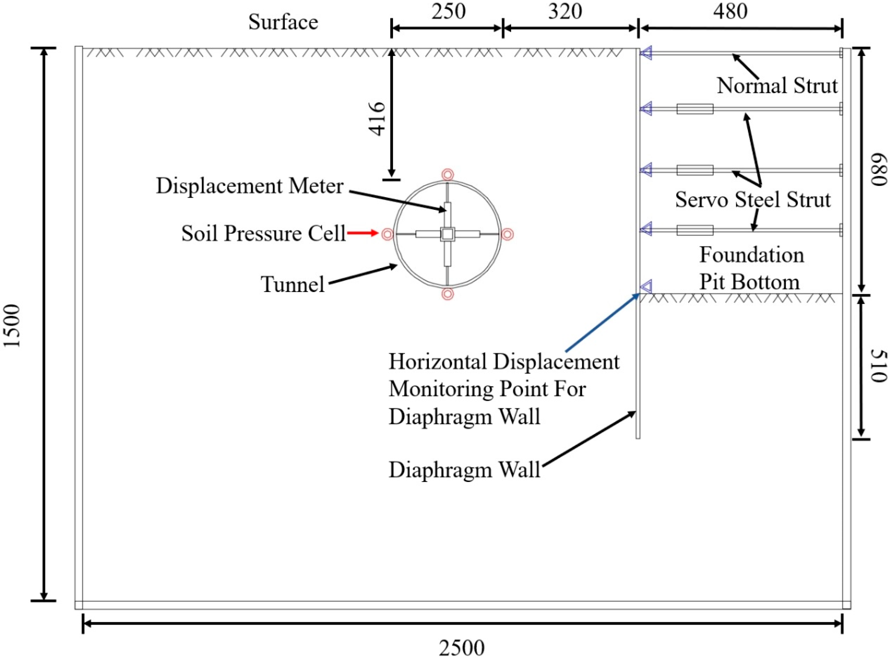
Figure 2 shows the test monitoring sections, where four monitoring sections Z1–Z4 are arranged on the same horizontal line as the internal struts and four monitoring sections M1–M4 are located between two adjacent internal struts. Figure 3 presents a cross-sectional view of the monitoring layout. Tunnel deformation is measured using displacement meters. On the eight monitoring sections comprising Z1–Z4 and M1–M4, one measuring point is arranged at 90° intervals around the section circumference; these measuring points enable simultaneous monitoring of tunnel horizontal displacement, vault settlement and convergence deformation. Tunnel ground pressure is tested via miniature soil pressure cells, with measuring points arranged at 90° intervals on section M3. The basis for selecting the M3 section as the main monitoring section is as follows: (1) The M3 section is located at the longitudinal midpoint of the tunnel and the center of the foundation pit excavation area, which is the section with the largest horizontal displacement and vault settlement of the tunnel under the influence of foundation pit excavation, and is the most unfavorable section for the tunnel structure; (2) the M3 section is the area where the servo loading has the most significant impact on the tunnel ground soil, and the soil pressure change here can reflect the maximum influence degree of servo loading.

2.3. Test Procedure and Test Conditions

First, after soil filling and device embedding, the entire model assembly is left to stand for 24 h, so as to ensure the completion of self-weight consolidation of the soil mass. The 24 h resting period was set based on Tang’s research [21] and the preliminary experimental results of this study. After the model assembly was left to stand for 24 h, the soil surface settlement rate decreased to below 0.01 mm/h, indicating that the self-weight consolidation of dry sand was essentially completed, thereby ensuring the accuracy and repeatability of the model test results. Then, the foundation pit is excavated in layers, with each layer excavated 170 mm, and one layer of internal strut is erected after each layer of excavation. After the foundation pit excavation is completed, the retractable device is controlled to simulate servo loading, thereby controlling the deformation of the side tunnel. The elongation distance of each layer of the servo steel strut is the maximum deformation of the diaphragm wall of this layer, measured by a laser range finder. Therefore, when a certain layer is servo-loaded, the deformation of the diaphragm wall at the strut of this layer is controlled to the state before excavation. According to the test purpose, the test conditions are designed as shown in Table 2.

3. Model Test Results Analysis

The influence of tunnel burial depth on the servo deflection correction effect is analyzed below based on the monitoring data of the model test (data not scaled up according to the similarity ratio).

3.1. Tunnel Horizontal Displacement

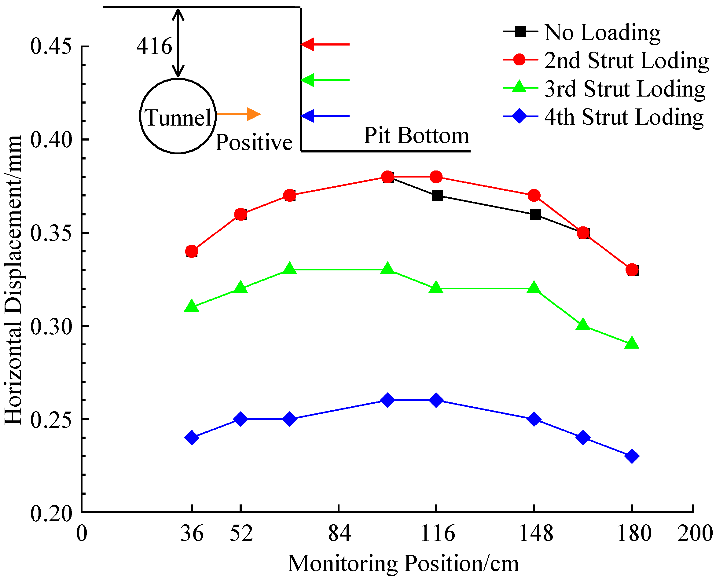
Figure 4 shows the control effect of servo loading on tunnel horizontal displacement when the tunnel burial depth is 416 mm. The horizontal axis is the longitudinal position of the measuring section in the tunnel (Figure 2), and the positive value of tunnel horizontal displacement on the horizontal axis indicates that the tunnel moves towards the inner side of the foundation pit. As shown in the figure, (1) after the foundation pit excavation is completed, the tunnel moves horizontally towards the foundation pit side, the horizontal displacement in the middle of the tunnel is greater than that at both ends, the maximum horizontal displacement is 0.38 mm, which occurs at the M3 section in the middle of the tunnel, and the tunnel horizontal displacement curve overall follows an inverted “U” shape. (2) After the completion of the second strut loading, the maximum horizontal displacement of the tunnel is still 0.38 mm, which has no obvious control effect on the tunnel horizontal displacement; after the completion of the third strut loading, the maximum horizontal displacement of the tunnel is 0.33 mm, the servo loading control is 0.05 mm, which reduces the tunnel horizontal displacement by 13.2%; after the completion of the fourth strut loading, the maximum horizontal displacement of the tunnel is 0.26 mm, the servo loading control is 0.12 mm, which reduces the tunnel horizontal displacement by 31.6%, and the fourth strut loading has a relatively obvious control effect on the tunnel horizontal displacement. (3) It can be seen that the closer the servo loading position is to the tunnel burial depth, the greater the control of tunnel horizontal displacement.
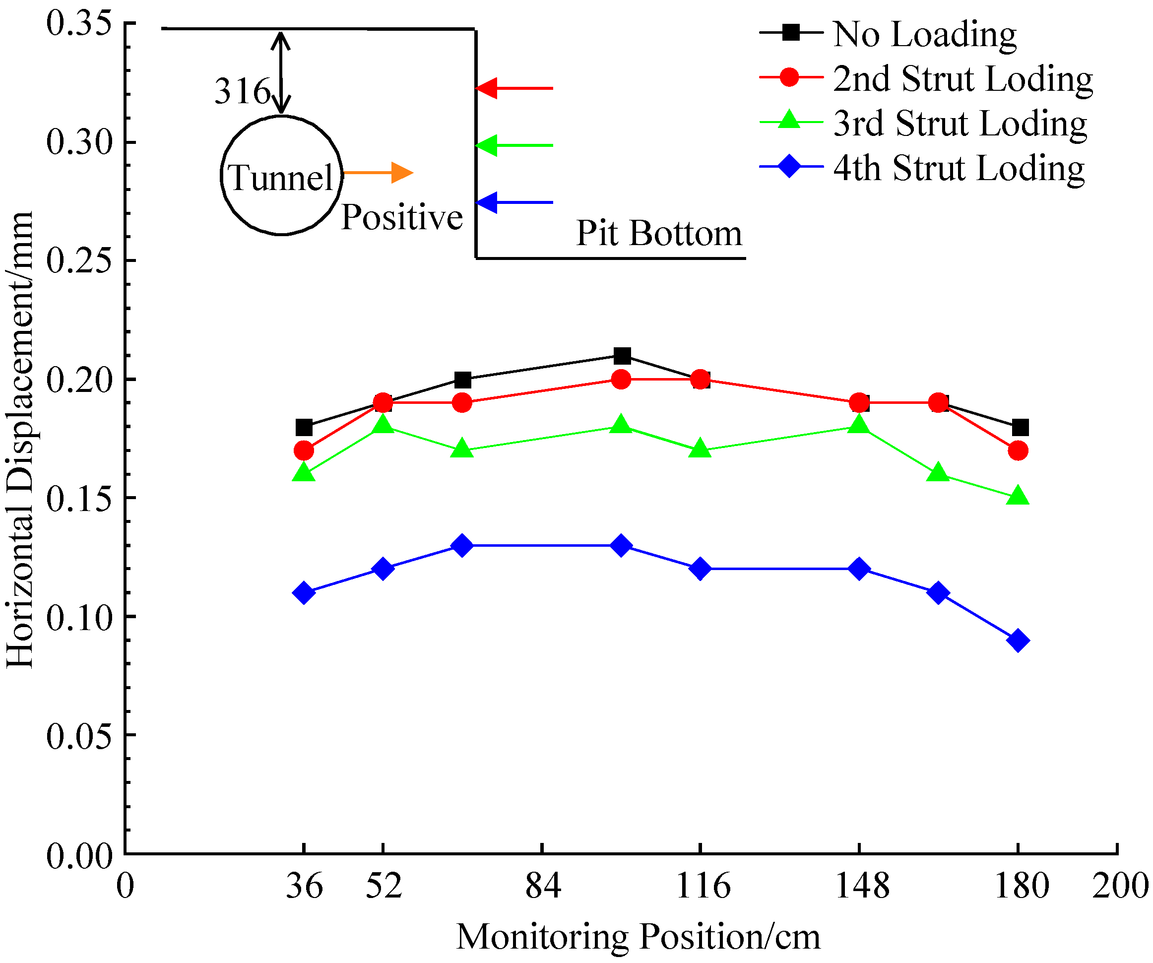
Figure 5 shows the control effect of servo loading on tunnel horizontal displacement when the tunnel burial depth is 316 mm. As shown in the figure, after the foundation pit excavation is completed, the maximum horizontal displacement of the tunnel is 0.21 mm. The second strut loading has no obvious control effect on the tunnel horizontal displacement; after the third strut loading, the maximum horizontal displacement of the tunnel is 0.18 mm, a decrease of 14.3%; after the fourth strut loading, the maximum horizontal displacement of the tunnel is 0.13 mm, a decrease of 38.1%.
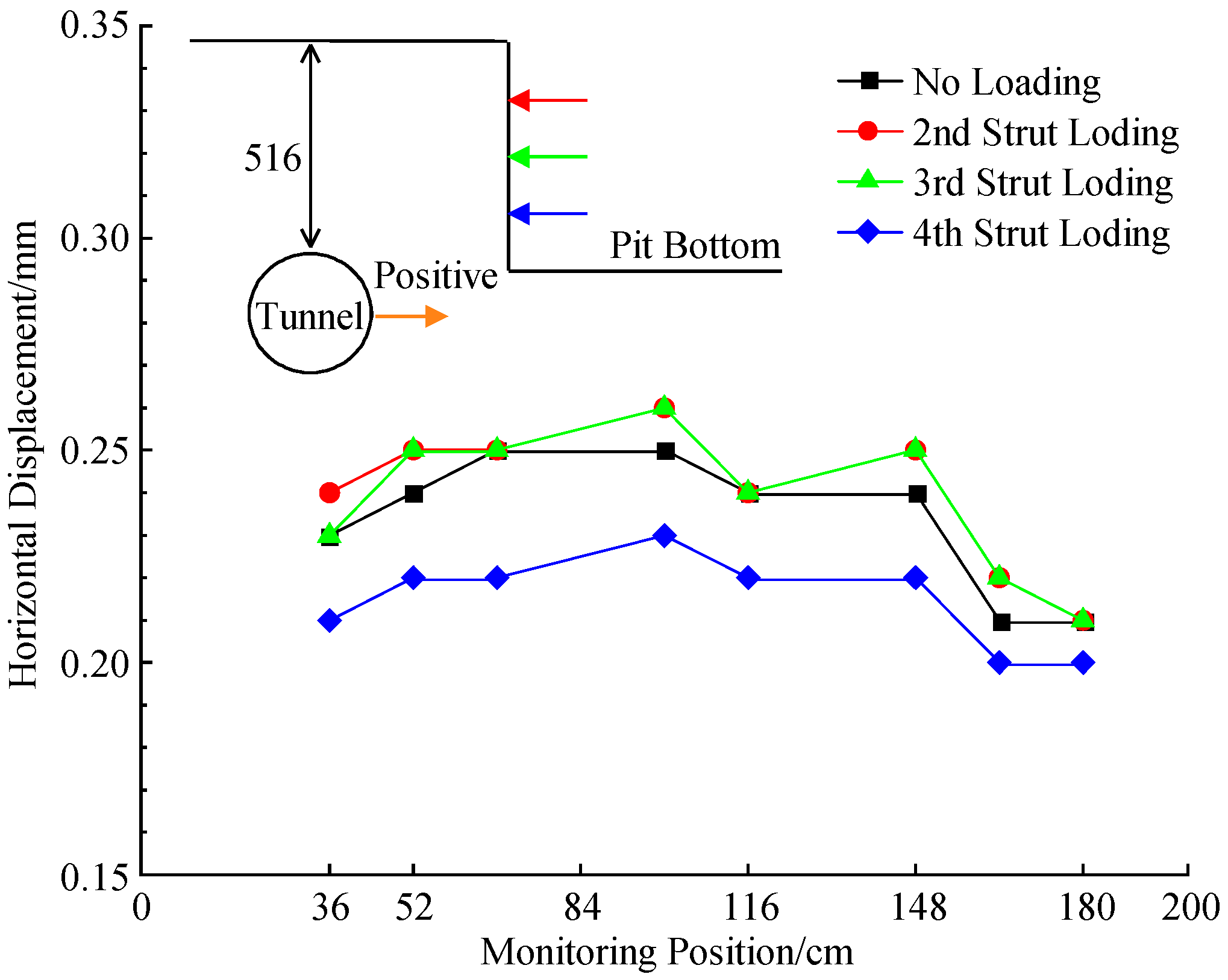
Figure 6 shows the control effect of servo loading on tunnel horizontal displacement when the tunnel burial depth is 516 mm. As shown in the figure, after the foundation pit excavation is completed, the maximum horizontal displacement of the tunnel is 0.25 mm. After the second and third layers of servo steel strut loading, the maximum horizontal displacement of the tunnel is 0.26 mm, which has a certain negative control effect on the tunnel horizontal displacement; after the fourth strut loading, the maximum horizontal displacement of the tunnel is 0.23 mm, a decrease of 8.0% compared with that before servo loading.
Comparative analysis of the above three test conditions shows that with the increase in tunnel burial depth, the horizontal displacement of the side tunnel caused by foundation pit excavation first increases and then decreases, which is consistent with the research results of Zhao et al. [29] on the influence of zoning on foundation pit excavation. Within the range of tunnel burial depth set in this test (316 mm~516 mm, prototype 7.9 m~12.9 m), with the increase in tunnel burial depth, the control effect of servo loading on tunnel horizontal displacement decreases continuously; when the tunnel vault is close to the bottom of the foundation pit (buried depth of 516 mm, prototype 12.9 m), servo loading does not produce a significant deformation control effect on the tunnel.
The essential mechanical mechanism is as follows: (1) The stress diffusion path of servo loading has an obvious spatial effect—with the increase in tunnel burial depth, the relative depth between the servo steel strut and the tunnel increases, the servo loading stress diffuses in deep soil in a fan shape, and the dissipation effect of additional stress on the side soil is more obvious, resulting in a decrease in the effective stress acting on the tunnel. (2) The soil stress transfer efficiency between the diaphragm wall and the tunnel decreases with the increase in tunnel burial depth—the deep soil has higher compactness and stronger shear dilatancy, and the shear deformation of the soil increases during the stress transfer process, leading to stress loss and the weakening of the servo deflection correction effect. In engineering, when the tunnel’s burial depth is greater than the foundation pit depth, other deformation control measures should be selected.
In addition, according to the research of Tang et al. [21] on the mechanical characteristics of adjacent tunnels and foundation pits during servo loading, the top strut loading has the least impact on the side tunnel. In this model test, with the increase in tunnel burial depth, the servo steel strut loading position moves relatively upward, so the deformation control effect is weakened, which is consistent with the conclusion of this paper.

3.2. Tunnel Vault Settlement

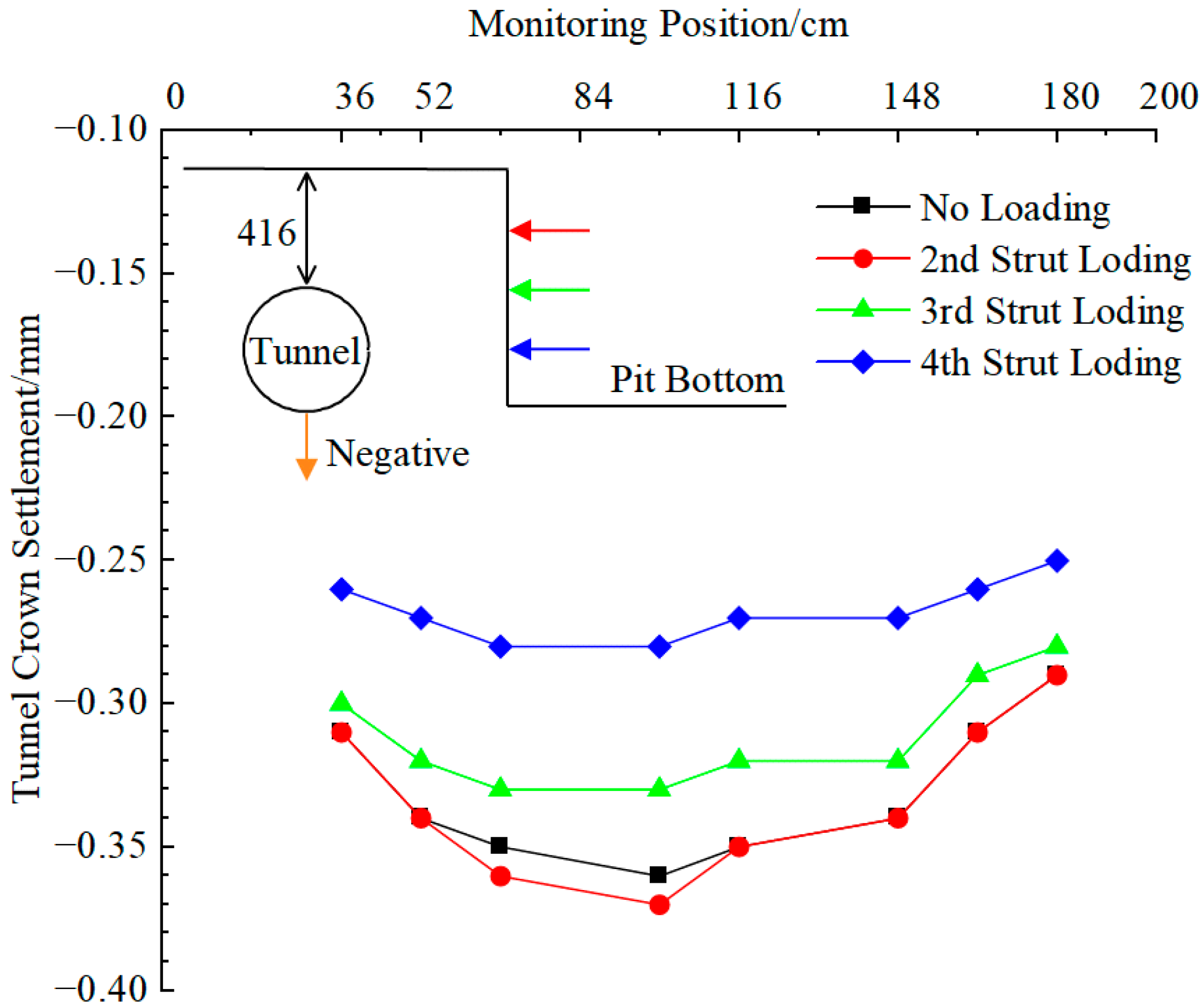
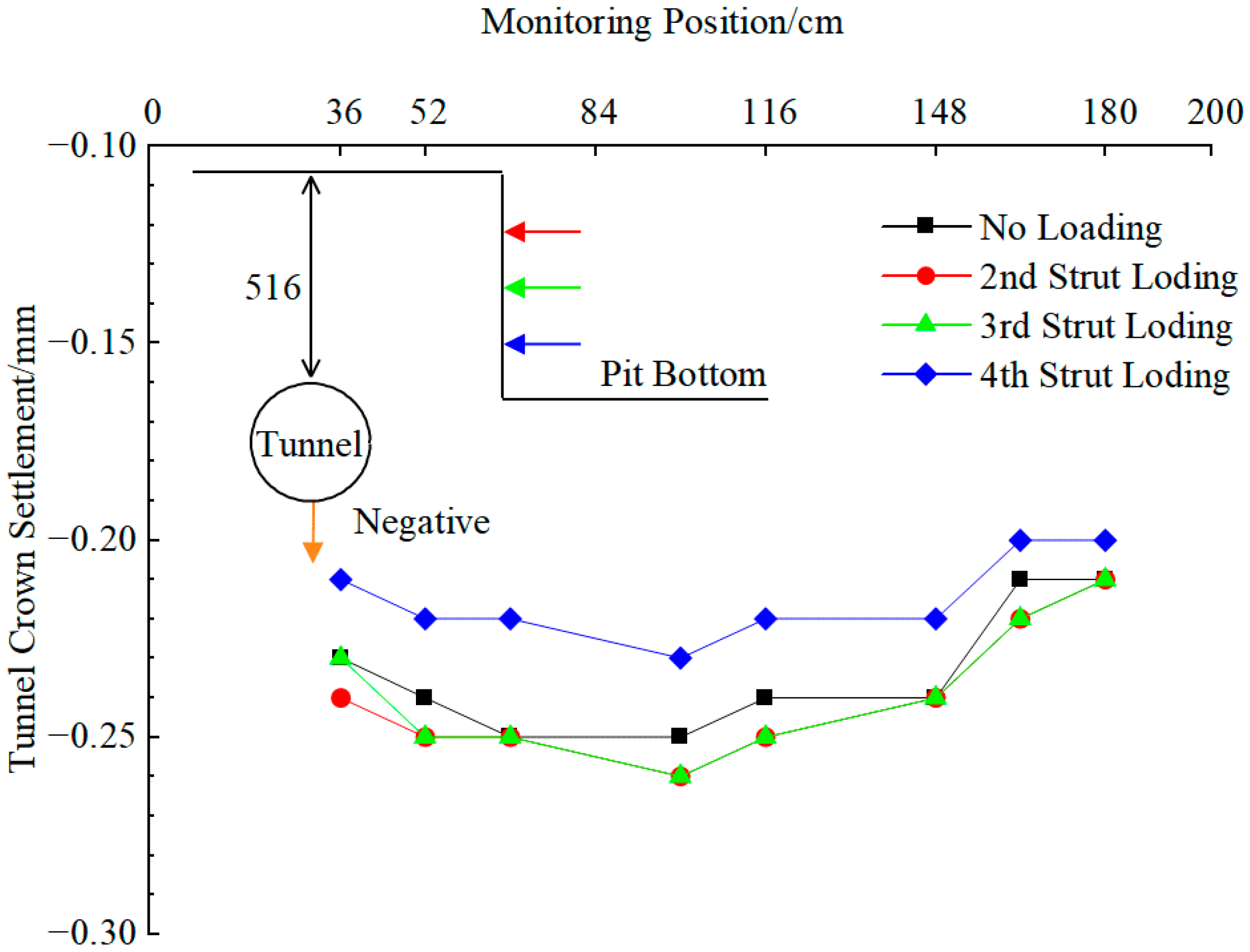
Figure 7 shows the control effect of servo loading on the tunnel vault when the tunnel burial depth is 416 mm. The negative value of vault settlement in the figure indicates vault subsidence. As shown in the figure, (1) after the foundation pit excavation is completed, the tunnel vault subsides, the vault subsidence in the middle of the tunnel is greater than that at both ends, the maximum vault subsidence is 0.36 mm, and the vault settlement curve is overall “U” shaped. (2) After the completion of the second strut loading, the maximum vault settlement of the tunnel is 0.38 mm, and the servo loading increases the tunnel vault settlement by 0.02 mm. The possible reason is that the second strut is above the tunnel and far away, and the servo loading disturbs the overlying soil of the tunnel, thereby increasing the tunnel vault subsidence. (3) After the completion of the third strut loading, the maximum vault settlement of the tunnel is 0.33 mm, the servo loading control is 0.03 mm, which reduces the maximum tunnel vault settlement by 13.9%, and the third strut loading has a certain control effect on the tunnel vault settlement. (4) After the completion of the fourth strut loading, the maximum vault settlement of the tunnel is 0.28 mm, the servo loading control is 0.08 mm, which reduces the tunnel vault settlement by 22.2%, and the fourth strut loading has a relatively significant control effect on the tunnel vault settlement.
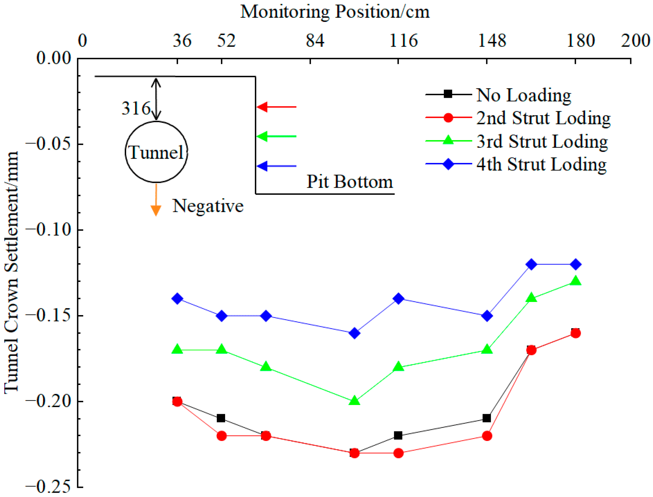
Figure 8 shows the control effect of servo loading on the tunnel vault when the tunnel burial depth is 316 mm. As shown in the figure, after the foundation pit excavation is completed, the maximum vault settlement of the tunnel is 0.23 mm. The second strut loading increases the tunnel vault settlement by 0.01 mm, producing a certain negative control effect; after the third strut loading, the maximum vault settlement of the tunnel is 0.20 mm, a decrease of 13.0% compared with that before servo loading; after the fourth strut loading, the maximum vault settlement of the tunnel is 0.16 mm, a decrease of 30.4%.
Figure 9 shows the control effect of servo loading on the tunnel vault when the tunnel burial depth is 516 mm. As shown in the figure, after the foundation pit excavation is completed, the maximum vault settlement of the tunnel is 0.26 mm. After the second and third layers of servo steel strut loading, the maximum vault settlement of the tunnel is 0.27 mm, which has a certain negative control effect on the tunnel vault settlement; after the fourth strut loading, the maximum vault settlement of the tunnel is 0.24 mm, a decrease of 7.7% compared with that before servo loading.
Comparative analysis of the above three test conditions shows that with the increase in tunnel burial depth, the relative position of the servo steel strut to the tunnel moves upward, the clear distance from the tunnel increases, the control effect of servo loading on tunnel horizontal displacement decreases, and the influence of tunnel burial depth on the control effect of vault settlement is consistent with the control law of horizontal displacement.

3.3. Ground Pressure Around the Tunnel

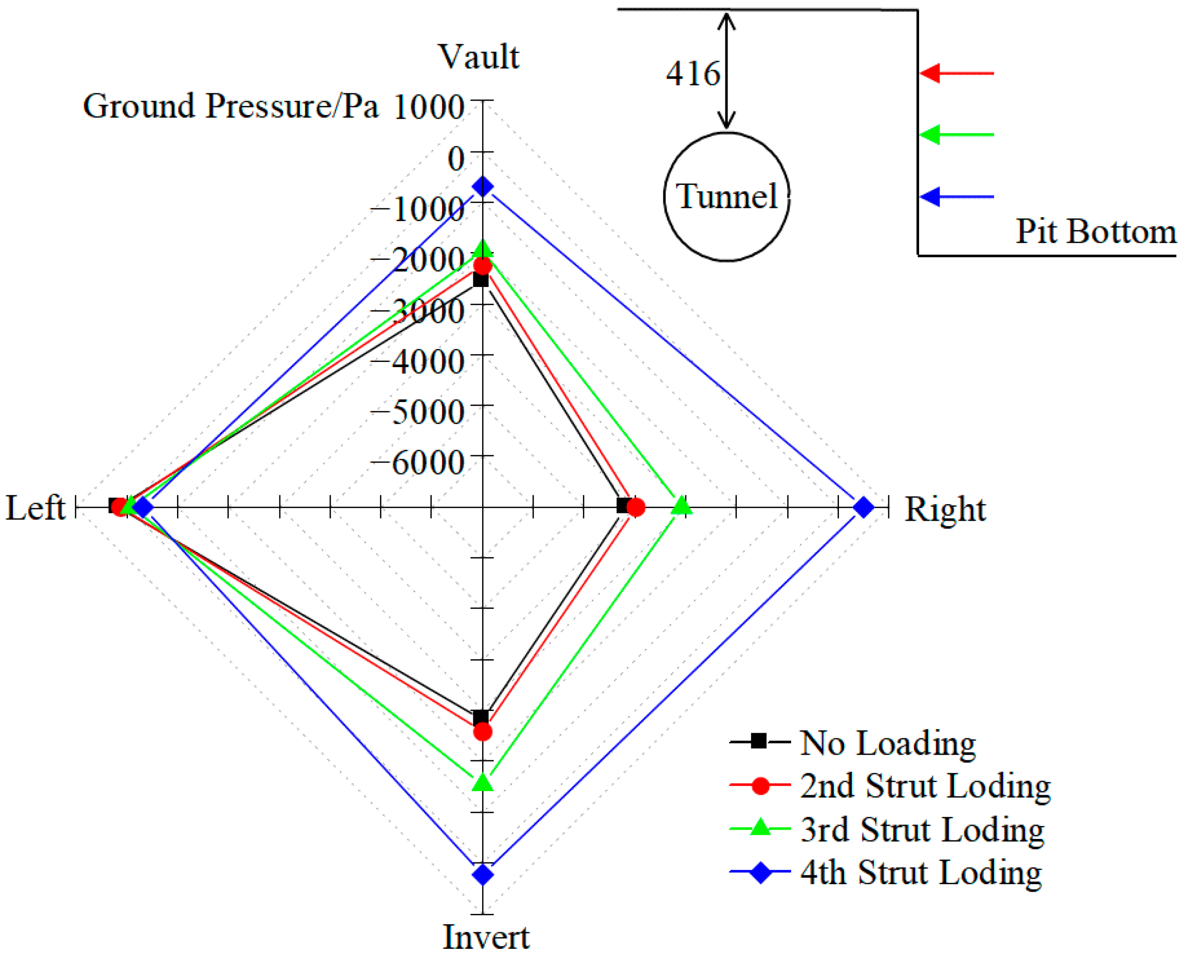
As shown in Figure 10, this figure presents the dynamic response of soil pressure at four key positions of the tunnel section (vault, invert, left hance, right hance) after foundation pit excavation and under graded servo loading stages, with the tunnel burial depth fixed at 416 mm. The core laws reflected in the figure are as follows: (1) After the foundation pit excavation is completed, the soil pressure at the vault, invert and right hance decreases, that is, the soil pressure changes from a static state to an active state. (2) With servo loading, the soil pressure at the vault, invert and right hance gradually increases, among which the soil pressure at the right hance increases the most, followed by the vault and invert, and the soil pressure at the left hance changes the least. (3) The increased amplitude of soil pressure is small during the second and third layers of servo loading, and the increased amplitude of soil pressure is the largest during the fourth strut loading. Taking the right hance as an example, the soil pressure decreases to −4194 Pa after the foundation pit excavation; after the second layer strut servo loading, the soil pressure is −3985 Pa, an increase of 5%; after the third strut loading, the soil pressure is −3087 Pa, an increase of 26.4%; after the fourth strut loading, the soil pressure becomes 493 Pa, an increase of 111.8%, and the soil pressure changes from the active soil pressure state after excavation to the passive soil pressure state. (4) It can be seen that although servo loading has a significant control effect on the deformation of the right hance of the tunnel, it is very easy to generate large additional stress here, bringing certain safety risks to the tunnel structure, which should be focused on in engineering.
Compared with the research of Tang et al. [21], the law of soil pressure change in this paper is consistent with it. However, due to the relatively large clear distance between the tunnel and the foundation pit in this test and the relatively small elongation of the servo steel strut, the soil pressure dissipation phenomenon is more obvious, so the influence degree of servo loading on the tunnel ground pressure in this paper is relatively small.
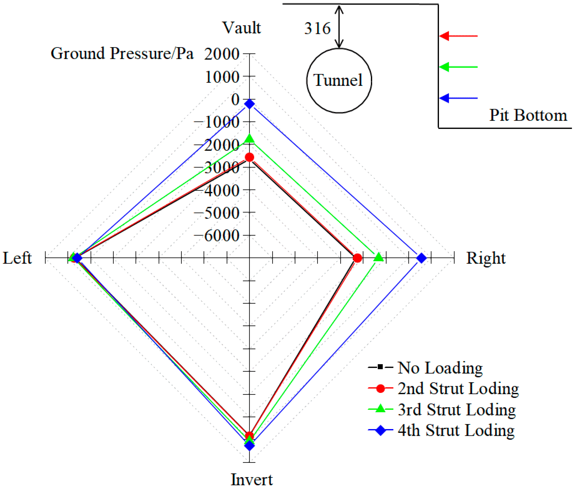
When the tunnel burial depth is 316 mm, the influence of servo loading on tunnel ground pressure is shown in Figure 11. After the foundation pit excavation is completed, the soil pressure at the right hance of the tunnel is −2329 Pa, and the soil pressure at the vault is −2644 Pa. After servo loading, the pressure at the right hance of the tunnel is −566 Pa, and the soil pressure at the vault is −214 Pa. The control range of servo loading on the soil pressure at the right hance of the tunnel is 125.0%, and the control range on the soil pressure at the vault is 91.9%.
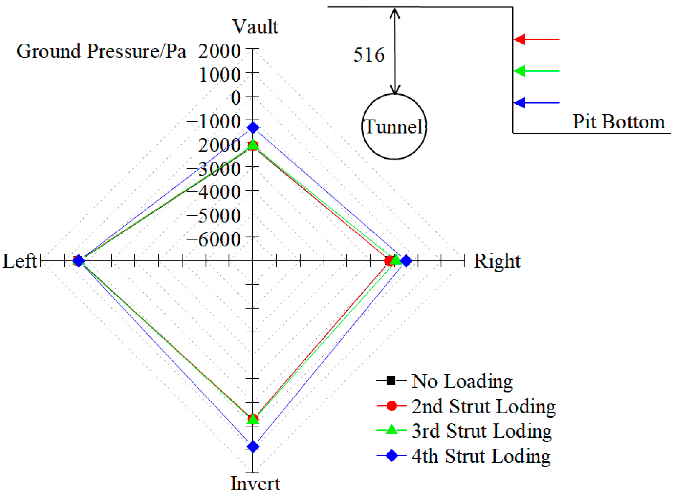
When the tunnel burial depth is 516 mm, the influence of servo loading on tunnel ground pressure is shown in Figure 12. After the foundation pit excavation is completed, the soil pressure at the right hance of the tunnel is −1176 Pa, and the soil pressure at the vault is −2163 Pa. After servo loading, the soil pressure at the right hance of the tunnel is −502 Pa, and the soil pressure at the vault is −1354 Pa. Servo loading reduces the soil pressure at the right hance of the tunnel by 57.0% and the soil pressure at the vault by 37.4%.
Comparative analysis of the above three test conditions shows that with the increase in tunnel burial depth, the control effect of servo loading on tunnel ground pressure decreases, and within the test buried depth range, the influence of tunnel burial depth on the control effect of vault settlement is consistent with the continuous decreasing law of horizontal displacement control effect. This is because the decrease in soil stress transfer efficiency between the diaphragm wall and the tunnel with the increase in tunnel burial depth not only weakens the servo control effect on tunnel deformation, but also makes the change in tunnel surrounding ground pressure caused by servo loading more gentle.

4. Numerical Simulation Analysis of Influencing Factors of Servo Deflection Correction

In this study, a three-dimensional finite element model is established to investigate the influence of tunnel burial depth on the servo deflection correction effect, which is verified by comparison with model tests. In addition, the effects of the net distance between the tunnel and the foundation pit, as well as the deformation control of the diaphragm wall on the servo deflection correction effect, are supplemented and analyzed, so as to provide targeted suggestions for engineering applications.

4.1. Model Development

To be consistent with the model test, dry sand is used to simulate the soil, and its basic parameters are shown in Table 1. The soil constitutive model adopts the Mohr–Coulomb model. The rationality of the constitutive model selection is explained in detail as follows:
(1) The research object of this study is homogeneous dry sand, and the whole research process focuses on the short-term construction process of foundation pit excavation and servo steel strut loading. The creep deformation of sand under short-term loading is extremely insignificant and can be ignored, so there is no need to consider the creep characteristics of the soil in this study.
(2) The Mohr–Coulomb model can accurately describe the shear strength characteristics and elastic–plastic deformation law of sand under the stress condition of foundation pit excavation, and the model parameters are easy to obtain through conventional geotechnical tests, which is highly consistent with the material parameters obtained from the model test in this paper.
(3) A large number of existing studies have shown that the Mohr–Coulomb model has sufficient calculation accuracy for the numerical simulation of foundation pit excavation in sandy soil strata [29,30], and can accurately predict the deformation of the enclosure structure and adjacent tunnels, which can fully meet the research needs of this paper.
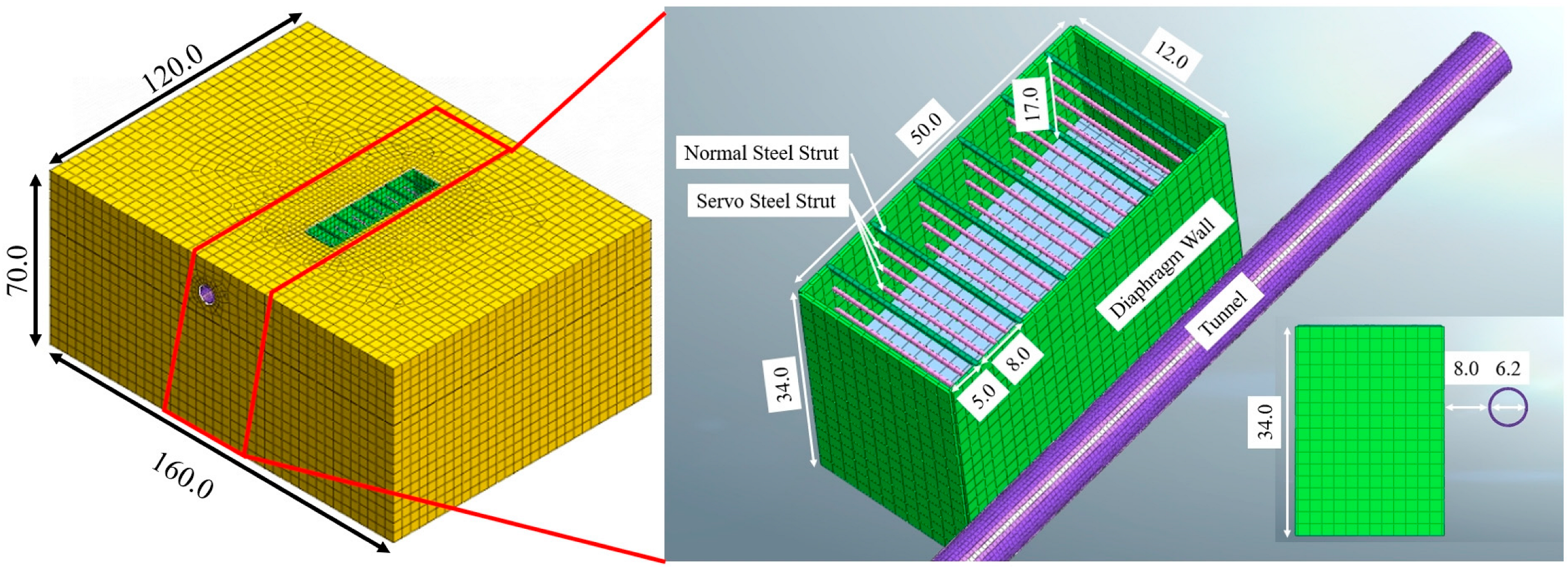
In this model, the shield tunnel segments and diaphragm walls are simulated by plate elements; the internal struts are simulated by beam elements; the servo loading is simulated by applying forced displacement. The parameter values of each component are shown in Table 3.
The three-dimensional finite element model is shown in Figure 13. The specific boundary conditions of the model are set as follows:
(1) The lateral boundaries (x = 0 and x = 160 m, y = 0 and y = 120 m) of the soil mass model adopt normal displacement constraints, that is, the horizontal displacement perpendicular to the boundary is restricted, and the horizontal displacement parallel to the boundary is free.
(2) The bottom boundary (z = 0 m) adopts fixed constraints, that is, both horizontal and vertical displacements are restricted.
(3) The top boundary (z = 70 m) is a free surface without any displacement and stress constraints.
(4) Structural components (diaphragm wall, tunnel, struts) are coupled with the soil mass through contact surfaces; the tangential contact adopts the Coulomb friction model with a friction coefficient of 0.35, and the normal contact adopts the hard contact model.
The mesh division scheme of the model is designed with graded refinement:
(1) The soil mass is discretized by 3D solid elements (C3D8R), the mesh density of the key area (within 20 m of the foundation pit and tunnel) is refined with a mesh size of 1 m, and the mesh density of the far area is gradually reduced with a mesh size of 5 m.
(2) The diaphragm wall and tunnel segments are discretized by plate elements (S4R) with a mesh size of 0.5 m.
(3) The internal struts and waist/crown beams are discretized by beam elements (B31) with a mesh size of 0.3 m. To verify the calculation accuracy of the model, mesh sensitivity analysis is carried out with three groups of mesh densities (coarse: mesh size of key area is 2 m; medium: mesh size of key area is 1 m; fine: mesh size of key area is 0.5 m).
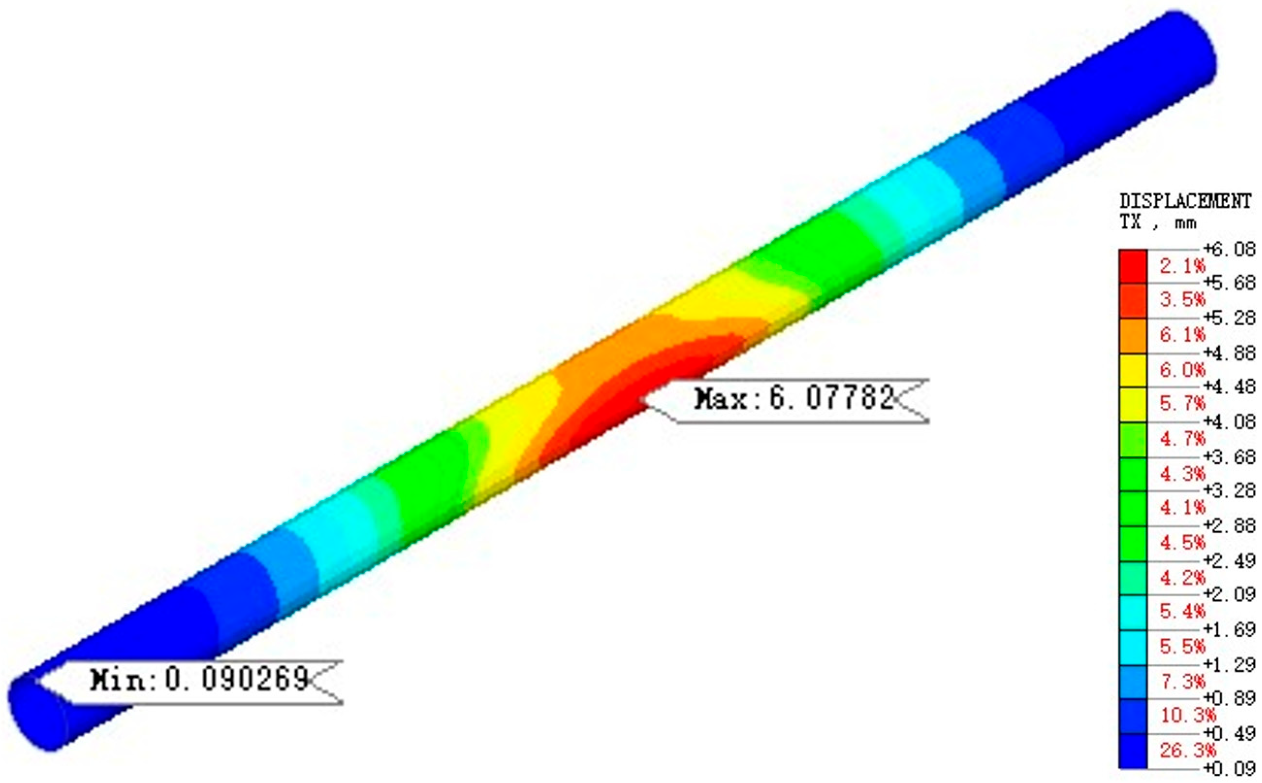
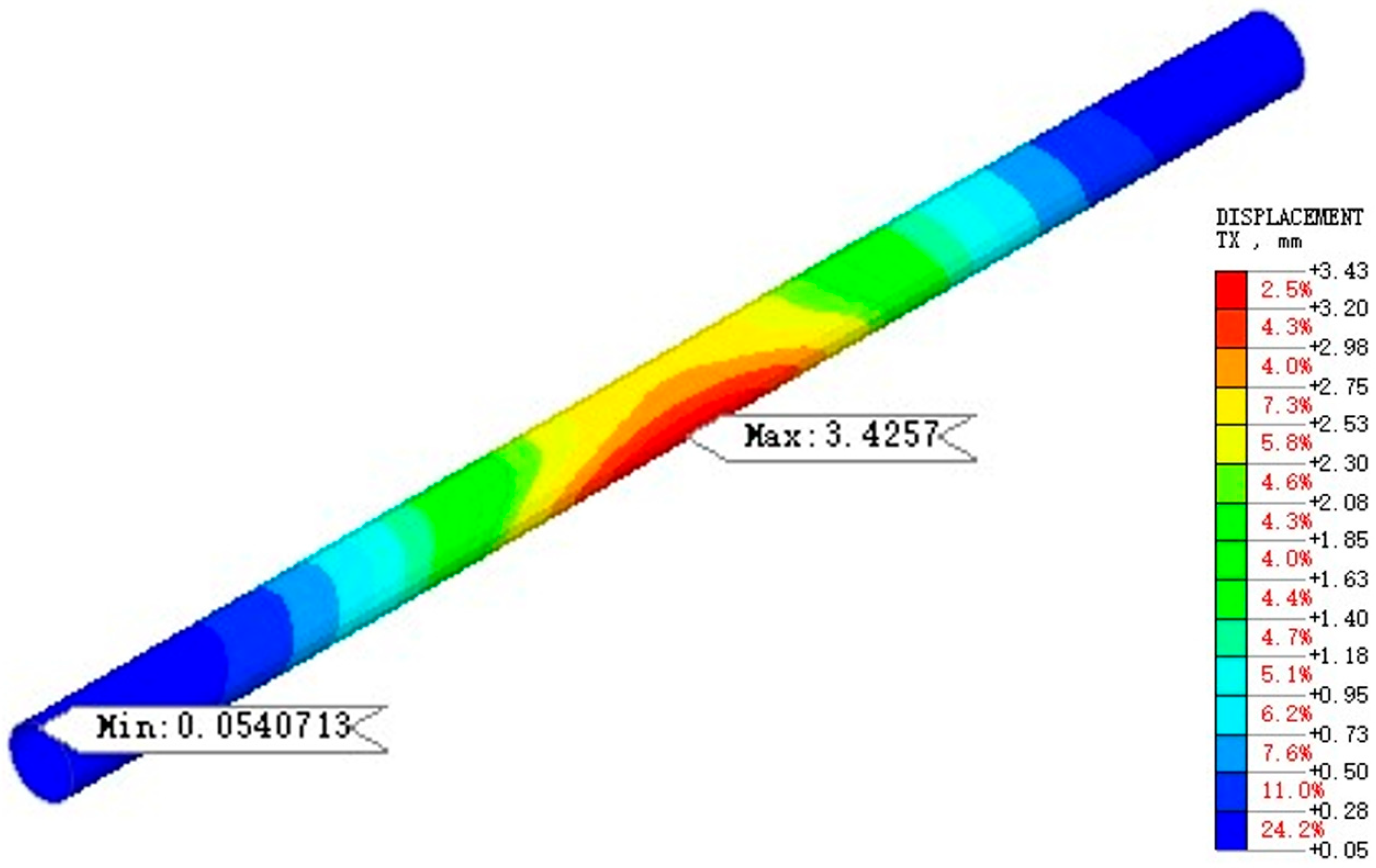
The results show that the maximum horizontal displacement of the tunnel calculated by the medium and fine mesh schemes is 6.08 mm and 6.12 mm, with a relative error of only 0.66%. This indicates that the medium mesh scheme adopted in this paper has high calculation accuracy and mesh independence, and can balance calculation efficiency and result accuracy.
The size of this model is set as length × width × height = 160 × 120 × 70 m. The foundation pit excavation size is: length × width × depth = 50 × 12 × 17 m, the thickness of the diaphragm wall is 1 m, the height is 34 m, and the embedded depth is 17 m; 6 horizontal struts are set in the horizontal direction, and four struts are set in the vertical direction (consistent with the model test). The first layer is a concrete strut, and the second, third and fourth layers are servo steel struts. The outer diameter of the steel strut is 609 mm, and the wall thickness is 16 mm. The outer diameter of the tunnel is 6.2 m, and the segment thickness is 0.35 m; the distance between the tunnel and the foundation pit is 8 m, and the tunnel burial depth (overburden thickness) is 10.4 m. The foundation pit excavation steps and servo loading conditions are consistent with the model test. Numerical simulations focus on horizontal displacement (the most critical tunnel safety index). Model tests have confirmed consistent variation laws of horizontal displacement, vault settlement and soil pressure, so numerical results can provide a reference for other indicators. According to the research purpose, the test conditions of numerical simulation are designed as shown in Table 4.

4.2. Verification of Numerical Simulation Results

Figure 14 shows the tunnel horizontal displacement after foundation pit excavation. It can be seen that the horizontal displacement in the middle of the tunnel is greater than that at both ends, which is consistent with the law of the model test.
Figure 15 shows the tunnel horizontal displacement after servo steel strut loading. As shown in the figure, servo steel strut loading reduces the tunnel horizontal displacement from 6.08 mm after foundation pit excavation to 3.43 mm, and servo loading reduces the tunnel horizontal displacement by about 43.6%.
The results for the other two tunnel burial depths are presented in Table 5. When the tunnel burial depth is 7.9 m, servo steel strut loading reduces the tunnel horizontal displacement by 47.4%; when the tunnel burial depth is 12.9 m, servo loading reduces the maximum tunnel horizontal displacement by 38.8%.
Comparative analysis of the above three test conditions shows that with the increase in tunnel burial depth, the relative position of the servo steel strut to the tunnel moves upward, the relative depth with the tunnel increases, and the control effect of servo steel strut loading on tunnel horizontal displacement decreases, which is consistent with the law of the model test. Under the standard condition, the maximum control range of the servo steel strut on the horizontal displacement of the side tunnel is 43.6%, and the maximum control range in the model test of this paper is 31.6%. There is a certain gap between the two, but they are in the same order of magnitude, which verifies the feasibility of the model test.
The possible reasons for the difference between the two are (1) due to the limitation of the model box size during the indoor test, the boundary effect is inevitable. (2) In the test, the rotation of the positive and negative thread nuts is used to control the expansion and contraction of the steel strut to simulate the servo steel strut loading. The elongation of the servo steel strut is obtained by converting the rotation angle of the nut, which has a certain error. (3) The aluminum rod simulates the servo steel strut in the model, and there may be a certain difference between its mechanical properties and the actual servo steel strut, which leads to deviations in the test results.

4.3. Influence of Clear Distance Between Tunnel and Foundation Pit

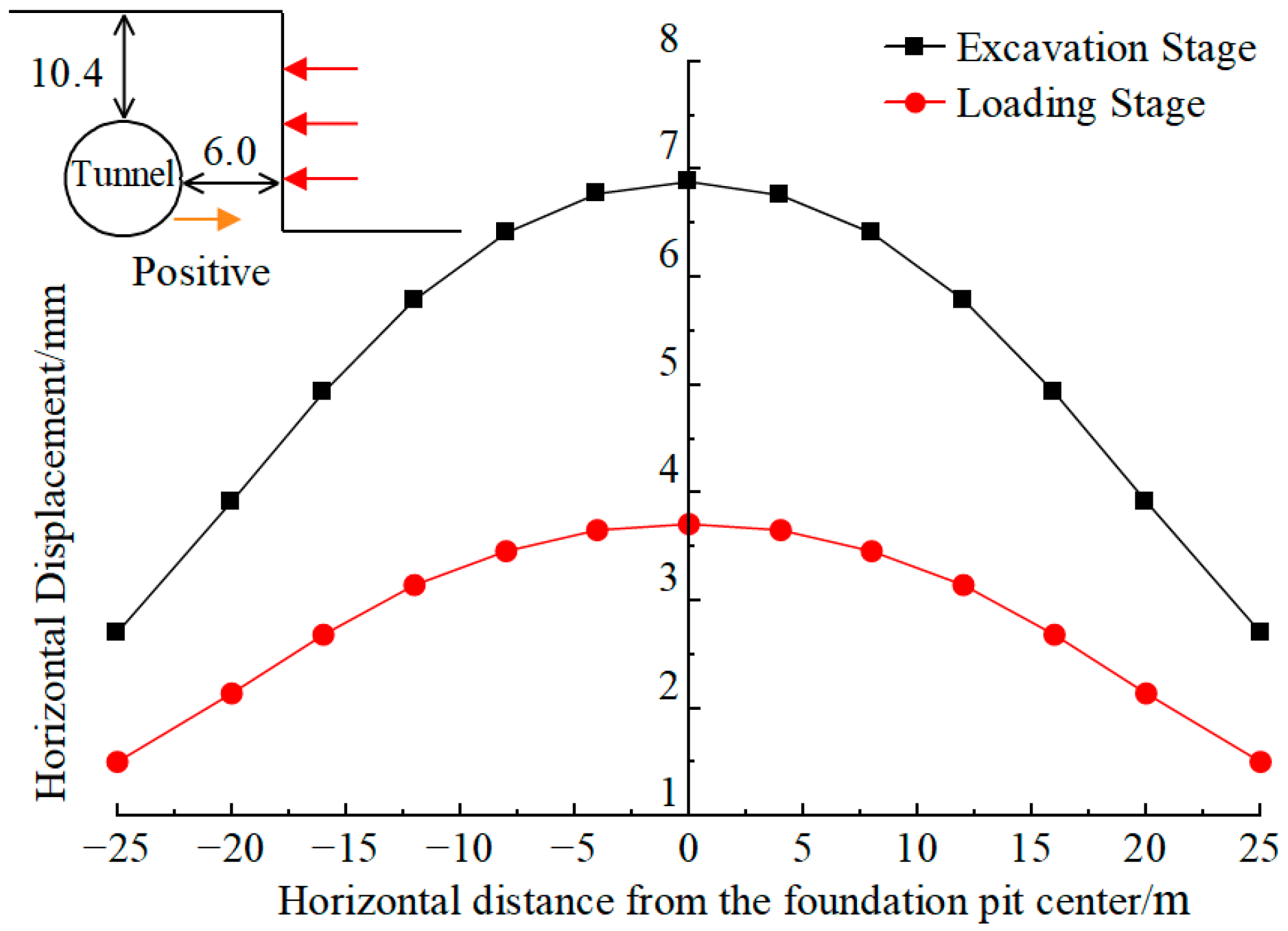
Figure 16 shows the horizontal displacement of the tunnel before and after servo loading under Test 4, where the horizontal axis represents the distance between the tunnel longitudinal direction and the foundation pit excavation center. As illustrated in the figure, after the completion of foundation pit excavation, the maximum horizontal displacement of the tunnel is 6.88 mm. Following servo steel strut loading, the maximum horizontal displacement is reduced to 3.31 mm, resulting in a servo steel strut loading control of 3.57 mm, which corresponds to a 51.8% reduction in tunnel horizontal displacement.
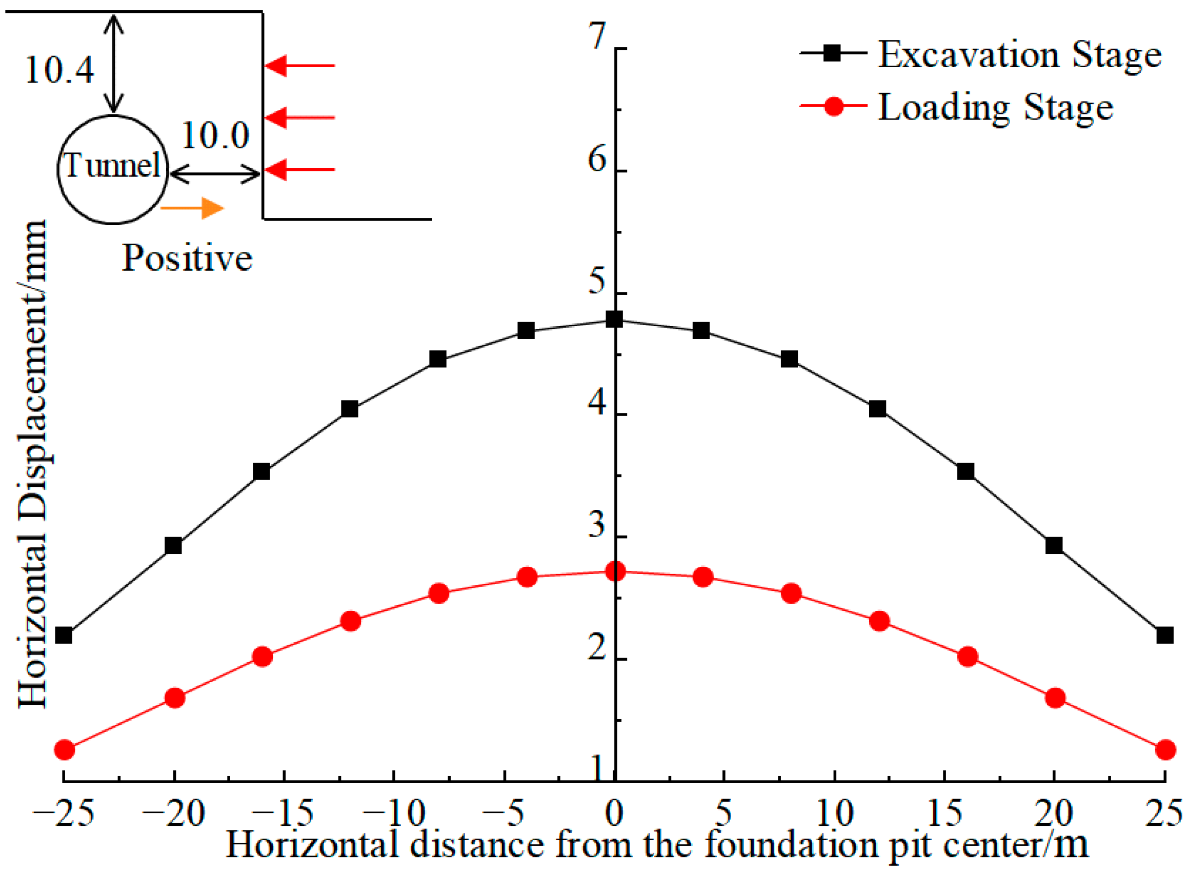
Figure 17 presents the horizontal displacement of the tunnel before and after servo steel strut loading under Test 5. As shown in the figure, when the clear distance between the tunnel and the foundation pit is 10 m, the maximum horizontal displacement of the tunnel after foundation pit excavation is 4.78 mm. After servo steel strut loading, the maximum horizontal displacement decreases to 2.93 mm, yielding a control of 1.85 mm and a 38.7% reduction in tunnel horizontal displacement. For a clear distance of 8 m, servo steel strut loading reduces the tunnel horizontal displacement by 43.6%.
A comparative analysis of the above three conditions indicates that as the clear distance between the tunnel and the foundation pit increases, the horizontal displacement of the adjacent tunnel induced by foundation pit excavation decreases, which is consistent with the findings of Zhang [30]. Furthermore, with an increasing clear distance, the servo steel strut loading control decreases, and the magnitude of the reduction in tunnel horizontal displacement achieved by servo steel strut loading also diminishes. In engineering practice, it is recommended to adopt servo steel struts to achieve an effective deflection correction effect when the clear distance between the tunnel and the foundation pit is less than 8 m. However, when the clear distance exceeds 10 m, the effectiveness of servo deflection correction is limited. In such cases, it is advisable to consider integrating other auxiliary deformation control measures.

4.4. Influence of the Diaphragm Wall’s Deformation Control Level

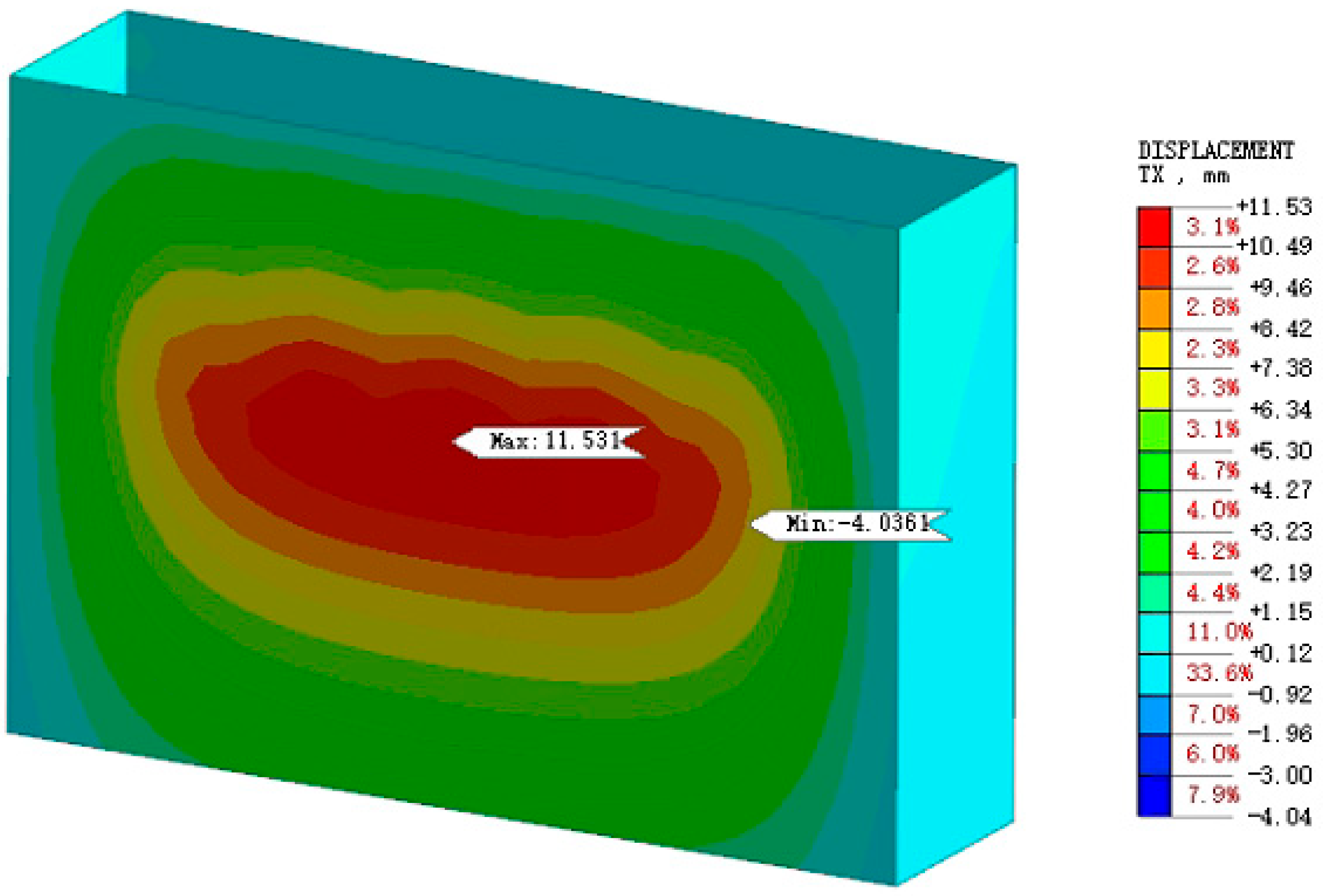
Figure 18 presents the deformation nephogram of the diaphragm wall after foundation pit excavation. It can be observed that the diaphragm wall exhibits an inward convex deformation pattern, with deformation in the central region being greater than that at the edges, and the maximum deformation reaches 11.53 mm.
The numerical model incorporates a total of 18 servo steel struts arranged in three layers and six columns (with the first layer being concrete struts). The deformations of the diaphragm wall at the locations of these 18 steel struts after excavation are listed in Table 6. The servo jacking process is simulated by applying forced displacements at the strut positions on the diaphragm wall. Specifically, when servo steel strut loading is activated for a particular layer, the deformation of the diaphragm wall at that layer is set to zero, aiming to control the deformation of the diaphragm wall at the strut points of that layer back to its pre-excavation state.
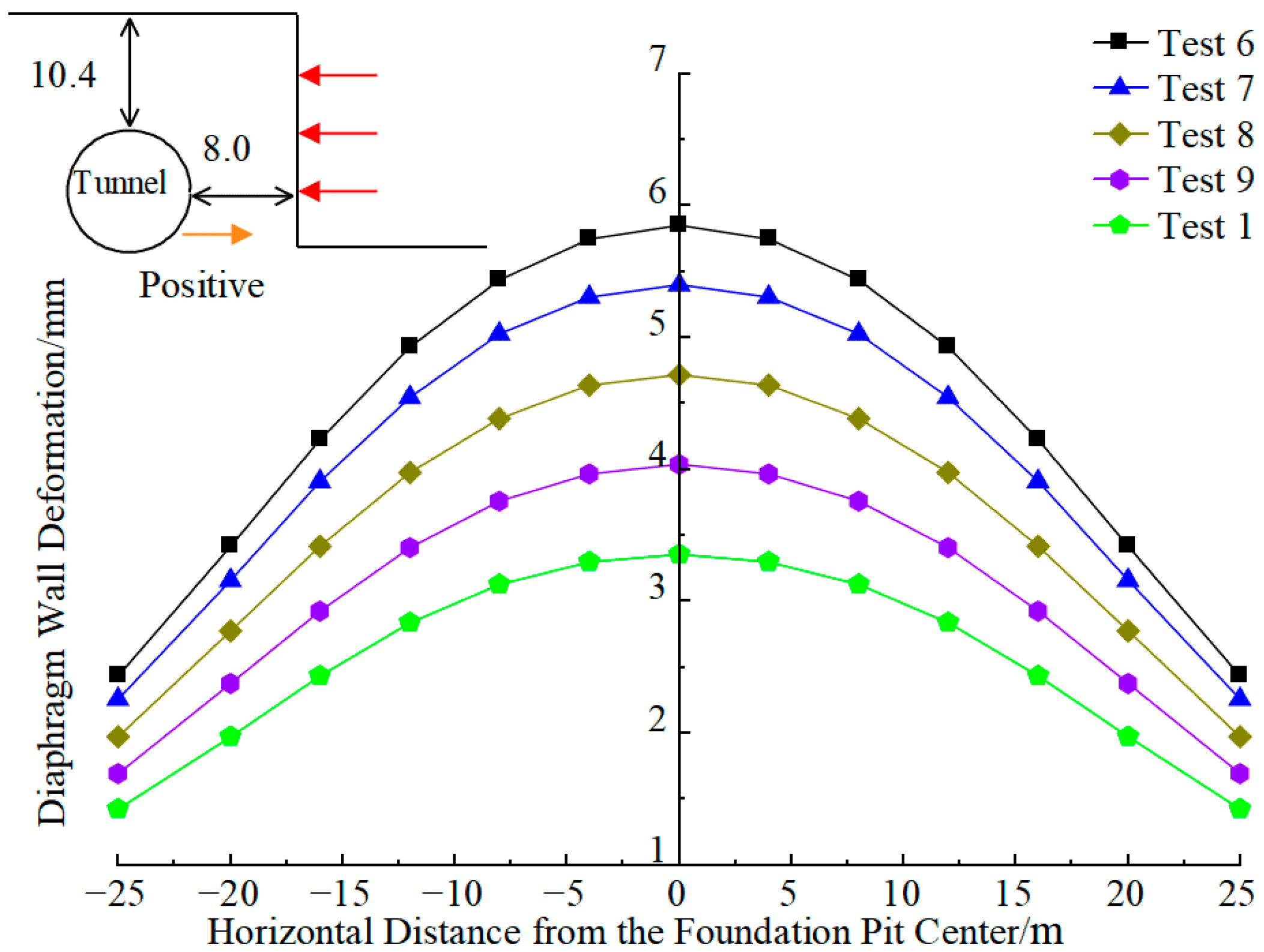
Figure 19 illustrates the effect of diaphragm wall deformation control on the horizontal displacement of the adjacent tunnel. The results indicate that the tunnel displacement control magnitude increases linearly with the increasing control magnitude of diaphragm wall deformation. A closer examination reveals a two-phase trend in the relationship between the servo deflection correction and the deformation control degree of the diaphragm wall. When the deformation control degree is below 50%, the servo deflection correction increases rapidly as the control degree rises. However, when the control degree exceeds 50%, the growth rate of the servo deflection correction gradually slows down.
This phenomenon can be attributed to the varying influence of the servo steel strut loading force on the ground soil. At lower deformation control degrees, the servo steel strut loading force is relatively small, resulting in limited disturbance to the soil around the tunnel and consequently a smaller deflection correction. As the deformation control degree increases, the servo steel strut loading force intensifies, leading to greater soil disturbance and a rapid increase in deflection correction. Once the deformation control degree reaches a certain threshold (around 50%), the ground soil becomes relatively stable, and the incremental effect of further loading diminishes, causing the growth rate of the servo deflection correction to decrease. These findings suggest that an optimal range of diaphragm wall deformation control exists for achieving efficient servo deflection correction in practical engineering applications.
The engineering physical meaning of the 50% deformation control degree inflection point is that it is the critical point where the soil around the foundation pit and tunnel transitions from the elastic deformation stage to the elastoplastic deformation stage, which is deduced based on the Coulomb constitutive model of the soil adopted in the numerical model and classical geotechnical mechanics theory of soil deformation. When the deformation control degree is less than 50%, the diaphragm wall and the ground soil are in the elastic deformation stage, the servo loading force is small, the soil has no plastic yield, and the stress transfer efficiency is high, so the servo deflection correction increases rapidly with the increase in deformation control degree. When the deformation control degree exceeds 50%, local plastic yield occurs in the soil around the foundation pit, shear failure of the soil is initiated, the stress transfer efficiency decreases, and the growth rate of the servo deflection correction slows down. A qualitative analysis of the inflection point variation under different tunnel burial depths and pit–tunnel clear distances shows that the inflection point has a slight variation trend with the change in the two factors: it shifts slightly upward with the decrease in tunnel burial depth and pit–tunnel clear distance, and shifts slightly downward with the increase in tunnel burial depth and pit–tunnel clear distance, with no obvious overall deviation.
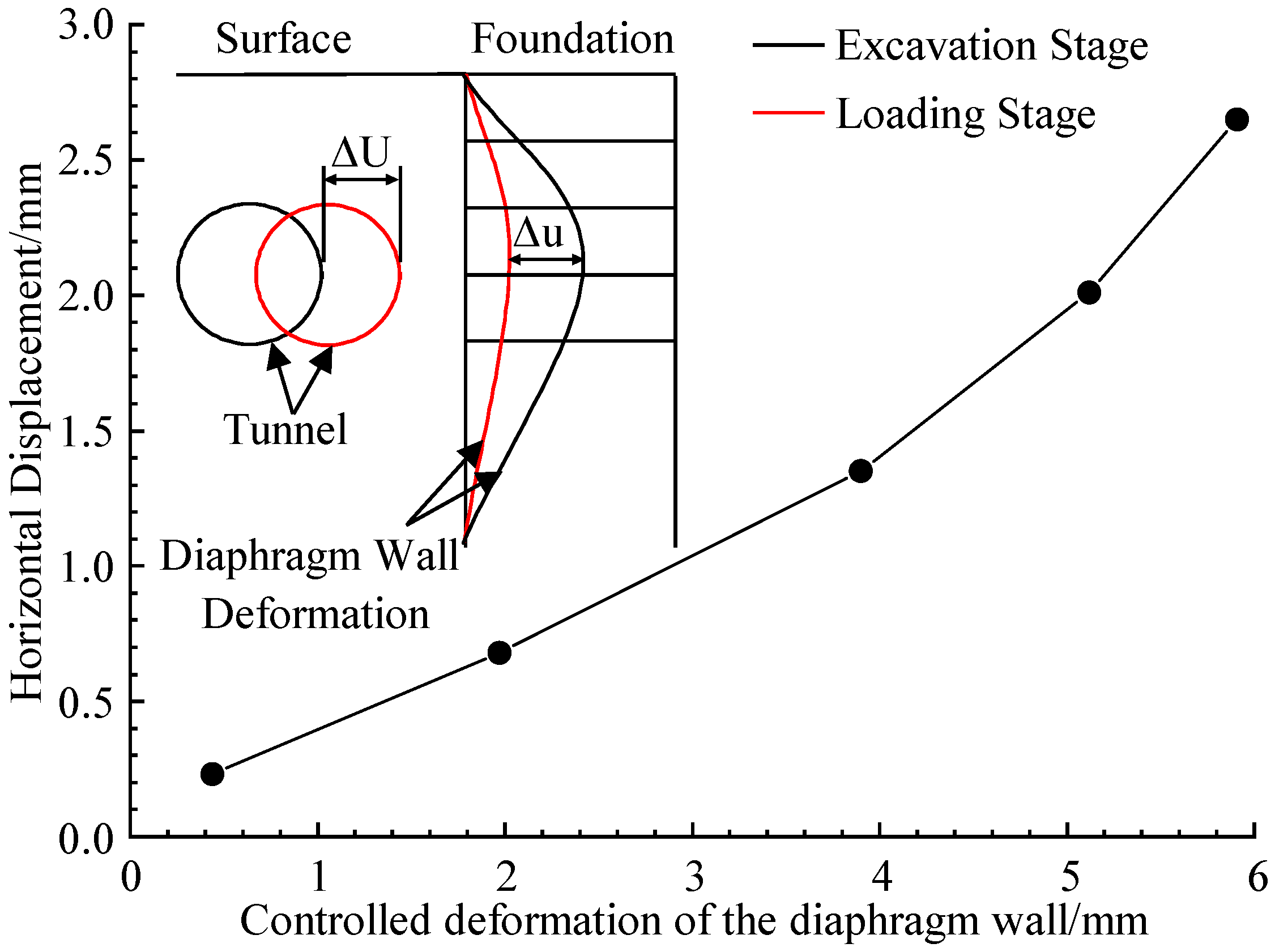
Based on the numerical simulation results, the relationship curve between the diaphragm wall deformation control Δ u and the tunnel horizontal displacement correction value Δ U is plotted in Figure 20. The curve exhibits a parabolic shape, indicating that as the diaphragm wall deformation control increases, the tunnel horizontal displacement correction value also increases, with the rate of increase gradually becoming larger. In engineering practice, it is advisable to appropriately increase the diaphragm wall deformation control to achieve a more significant tunnel correction effect and enhance the efficiency of servo loading.

4.5. Establishment of Prediction Formula for Servo Deflection Correction

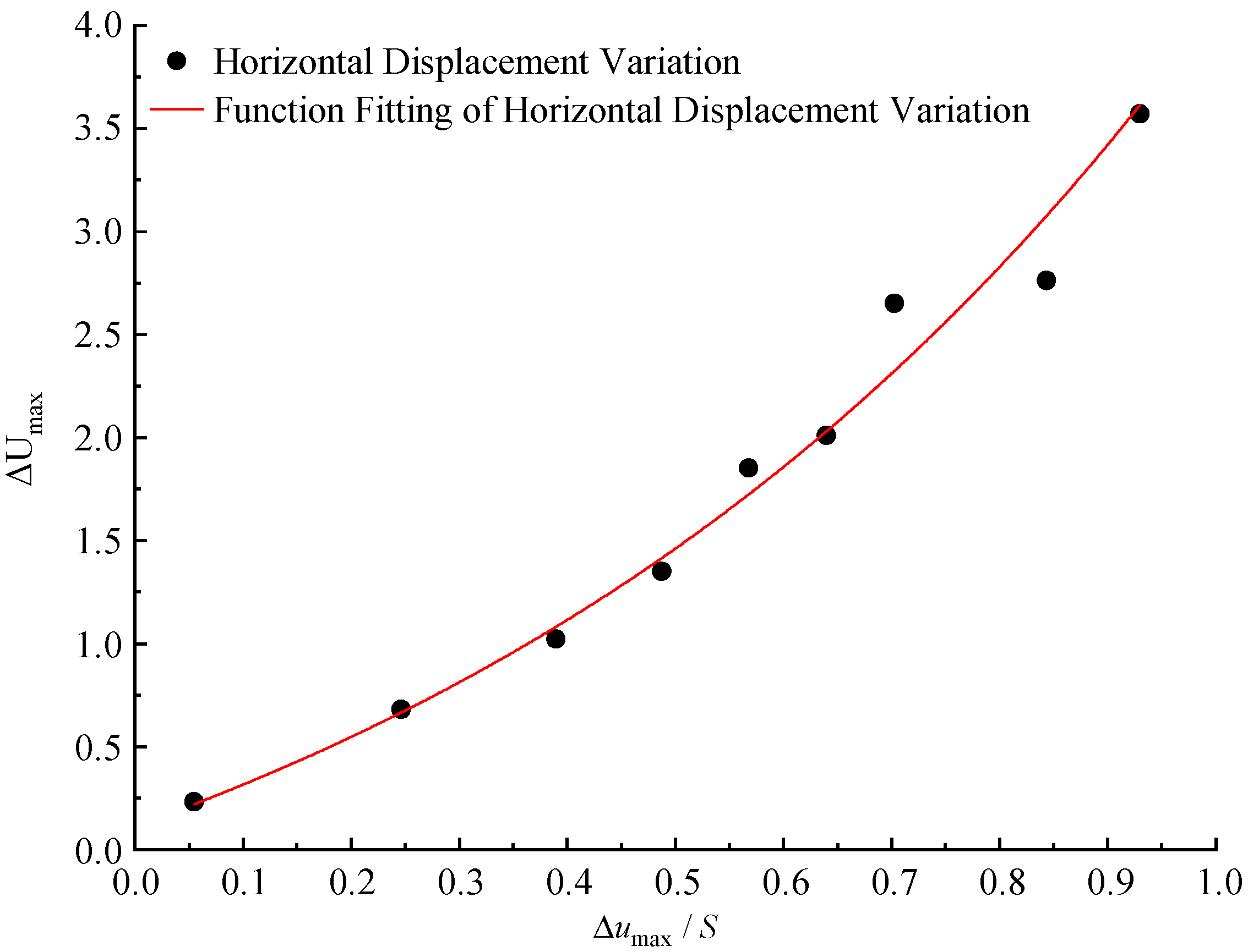
Based on the numerical simulation results in this study, the relationship between Δ U max and Δ u max / S under various test conditions is presented in Table 7. Table 7 summarizes the quantitative results of the maximum deflection correction of the tunnel under 15 groups of combined working conditions, with the diaphragm wall deformation control ranging from 5% to 100% and the clear distance ranging from 6 m to 10 m. It can be observed that the deformation control of the diaphragm wall and the clear distance between the tunnel and the foundation pit are critical parameters influencing the servo deflection correction effect of the tunnel. Specifically, the maximum horizontal displacement correction value Δ U max of the tunnel is positively correlated with the maximum deformation control Δ u max of the diaphragm wall, while it is negatively correlated with the clear distance S between the tunnel and the foundation pit. Therefore, a coupling analysis of these two parameters can be conducted to investigate the relationship between Δ U max and Δ u max / S under the standard burial depth of the tunnel.
As shown in Figure 21, the data are fitted using a single exponential decay function (ExpDec1). The fitted equation is given by:
Δ U max = A × exp u max / S / t + y 0
In the equation, A is the decay amplitude, t is the decay constant, and y 0 is the baseline offset (the final asymptotic value that the exponential decay approaches).
The fitting procedure yielded the following parameters, A = 1.408 ± 0 , t = 0.744 ± 0 , y = 1.296 ± 0 . Confidence interval at 95% confidence level is provided in parentheses. The coefficient of determination, R2, was calculated to be 1.0.
It is found that the relationship between the maximum horizontal displacement correction value Δ U max and Δ u max / S approximately follows an exponential function:
Δ U max = 1.408 × exp 1.343 u max / S 1.296
To verify the accuracy of the proposed prediction formula, validation was conducted using the model test data in this study. The model test conditions were substituted into Equation (1) for calculation. The prototype of the standard test condition (tunnel burial depth of 416 mm, clear distance of 320 mm, diaphragm wall deformation control of 11.53 mm) was used for validation. The predicted maximum horizontal displacement correction value of the tunnel is 2.58 mm, and the measured value from the numerical simulation is 2.65 mm, with a relative error of only 2.64%. For the other 8 groups of test conditions in Table 7, the relative errors between the predicted values and the simulated values are all less than 8%, which verifies the high accuracy of the formula within the set working conditions.
Building on this verification, to further clarify the engineering applicability boundaries of the prediction formula, we systematically delineated the actual engineering scope based on the model tests and numerical simulations as follows: (1) Tunnel burial depth (overburden thickness): 7.9 m~12.9 m (the ratio of tunnel burial depth to foundation pit depth is 0.46~0.76, which is the main influence range of foundation pit excavation). (2) Pit–tunnel clear distance: 6 m~10 m (the effective action range of the servo steel strut loading). (3) Diaphragm wall deformation control degree: 5~100% (the conventional control range of servo loading in engineering). (4) Engineering geological conditions: homogeneous sandy soil with a direct shear internal friction angle of 35° and cohesion of 0 kPa (for other soil types, the formula can be adjusted by modifying the fitting parameters).
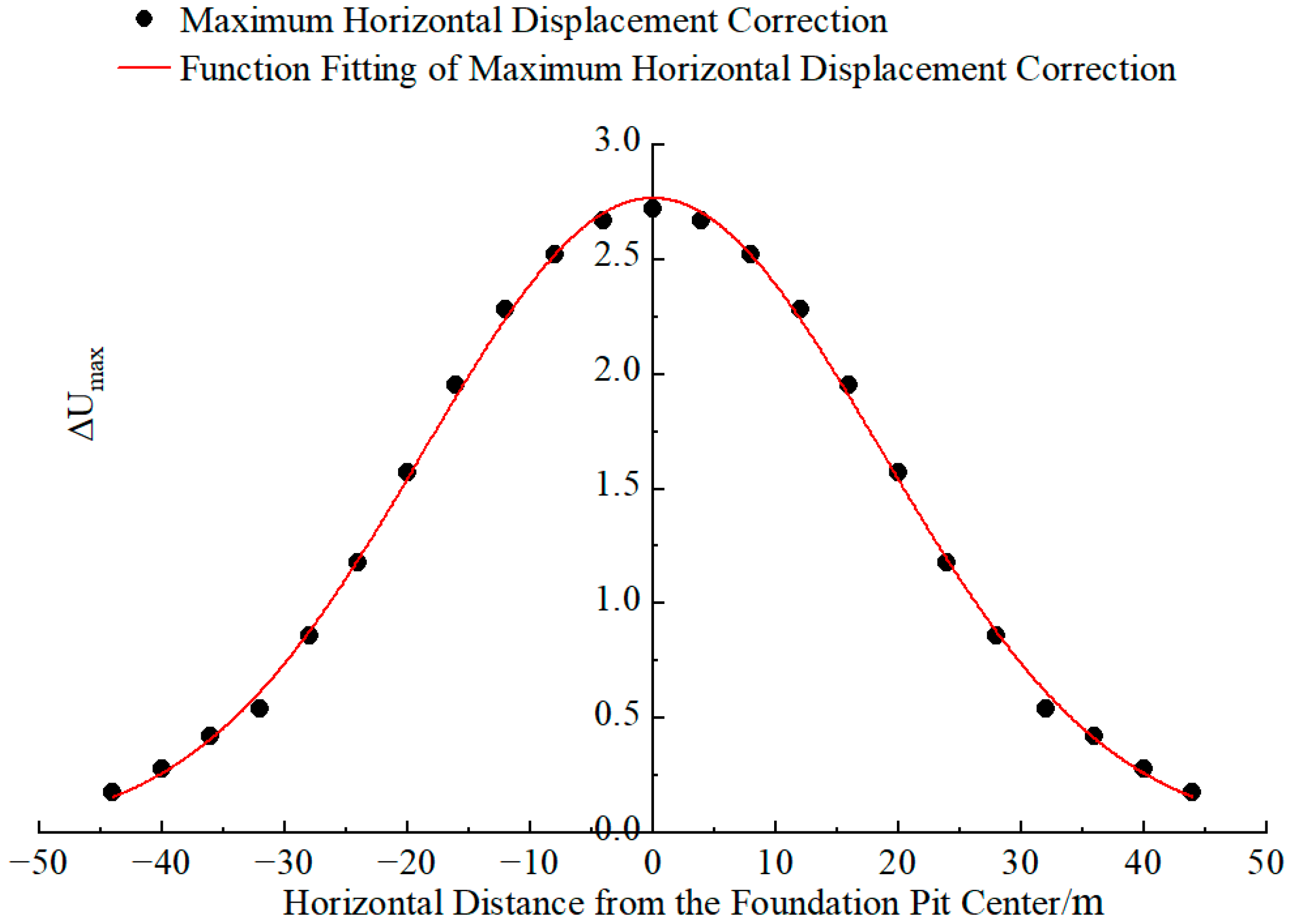
As shown in Figure 22, based on the numerical simulation results, the deflection correction of the tunnel within the influence range of servo loading follows a normal distribution, which is consistent with the theoretical derivation results of Zhu [18]. Based on the normal distribution function formula, through data fitting, the distribution function for the tunnel horizontal displacement correction value Δ U x (unit: mm) at a distance x (unit: m) from the foundation pit excavation center is proposed as follows:
Δ U x = Δ U max × exp 2 x 37.116 2
where Δ U x is the maximum horizontal displacement correction value of the tunnel; x is the horizontal distance from the calculation point to the foundation pit center.
Substituting Equation (3) into Equation (4), the distribution function of the tunnel servo deflection correction, considering the deformation control of the diaphragm wall and the clear distance between the tunnel and the foundation pit, is obtained as follows:
Δ U x = 1.408 exp 1.343 Δ u max / S 1.296 × exp 2 x 37.116 2

4.6. Consistency of Deformation Indicators

Model tests show that the deflection correction effects of tunnel horizontal displacement, crown settlement and surrounding soil pressure follow highly consistent laws. The influence of pit–tunnel clear distance and diaphragm wall deformation control revealed by numerical simulations can be extended to other indicators. The proposed prediction formula can also provide a quantitative reference for the preliminary design of servo systems targeting other deformation controls.

5. Conclusions and Recommendations

5.1. Conclusions

Through model tests and numerical simulations, the influencing factors of the servo deflection correction of the side shield tunnel are systematically studied, and the prediction formula and longitudinal distribution law of the servo deflection correction are proposed. The main conclusions are as follows:
(1) Within a wider range of tunnel burial depth, the servo deflection correction first increases and then decreases with the increase in tunnel burial depth: when the ratio of tunnel burial depth to foundation pit depth is less than 0.3, the correction effect increases with the increase in buried depth; when the ratio exceeds 0.3, the correction effect decreases continuously with the increase in buried depth. Within the test range of this study (the ratio of tunnel burial depth to foundation pit depth is 0.46~0.76, which is the main influence range of foundation pit excavation), the servo deflection correction effect decreases continuously with the increase in tunnel burial depth. When the tunnel vault is close to the bottom of the foundation pit, the servo loading does not produce a significant deflection correction effect, and the control law of servo loading on tunnel ground pressure is consistent with the deflection correction effect law.
(2) The servo deflection correction is negatively correlated with the clear distance between the tunnel and the foundation pit. The closer the tunnel is to the foundation pit, the better the servo deflection correction effect; when the clear distance is greater than 10 m, the servo deflection correction effect is limited.
(3) The servo deflection correction is positively correlated with the deformation control of the diaphragm wall, and the relationship curve is parabolic. When the deformation control degree of the diaphragm wall is less than 50%, the servo deflection correction increases rapidly with the increase in the deformation control degree; when the deformation control degree is greater than 50%, the growth rate slows down.
(4) The servo deflection correction is approximately exponentially related to the ratio of the deformation control of the diaphragm wall to the clear distance between the tunnel and the foundation pit, and the prediction formula of the servo deflection correction considering the clear distance between the tunnel and the foundation pit and the deformation control of the diaphragm wall is established, with high prediction accuracy.
(5) The servo deflection correction presents a normal distribution along the longitudinal direction of the tunnel, with the maximum value in the middle section of the tunnel and smaller values at both ends.
(6) There is an inherent discrepancy between the scaled model test and the full-scale numerical simulation results due to the boundary effect, size effect, and mechanical property differences in model materials. The absolute values of the servo deflection correction obtained in this study are based on specific test conditions, and when generalizing the results to actual engineering projects with different geological conditions, structural sizes, and construction parameters, appropriate correction and on-site verification must be carried out according to the specific project conditions.

5.2. Engineering Recommendations

Based on the above research conclusions, the following engineering recommendations are proposed for the active control of side shield tunnel deformation by servo steel struts in deep metro foundation pit engineering:
(1) For the side shield tunnel adjacent to the deep metro foundation pit, when the tunnel burial depth is within the main influence range of foundation pit excavation (the ratio of tunnel burial depth to foundation pit depth is 0.6~0.8 (corresponding to a servo deflection correction efficiency of 40~45% in this study), the servo steel strut can be used to achieve a good deflection correction effect; when the tunnel burial depth is greater than the foundation pit depth (correction efficiency < 39% in this study), other deformation control measures (such as isolating pile walls) should be combined to ensure the safety of the tunnel structure.
(2) When the clear distance between the tunnel and the foundation pit is less than 8 m (corresponding to a tunnel horizontal displacement correction rate of over 43.6% in this study), the servo steel strut can be used as the main deformation control measure; when the clear distance is 8~10 m (correction rate of 38.7~43.6% in this study), the servo steel strut can be used in combination with other auxiliary measures; when the clear distance is greater than 10 m (correction rate < 38.7% in this study), the use of servo steel struts is not recommended due to the limited deflection correction effect.
(3) In the design of servo loading parameters, the deformation control degree of the diaphragm wall can be set to 50~75% (corresponding to a tunnel horizontal displacement correction of 1.35 mm to 2.01 mm in this study, accounting for 50.9~75.8% of the maximum correction), which can not only ensure a good servo deflection correction effect but also avoid excessive servo loading force leading to excessive additional stress on the tunnel structure and diaphragm wall.
(4) In the process of engineering construction, the longitudinal distribution law of the servo deflection correction should be considered, and more monitoring points should be arranged in the middle section of the tunnel to strengthen the real-time monitoring of tunnel deformation; the monitoring frequency should be appropriately increased during servo loading to timely adjust the servo loading parameters according to the monitoring data.

5.3. Applicable Scope of Research Conclusions

The model test and numerical simulation in this paper are carried out based on homogeneous dry sand strata, and the research conclusions are mainly applicable to sandy soil strata with high strength and low compressibility. Additionally, this study focuses on horizontal displacement correction. Systematic numerical analysis of crown settlement and soil pressure under multi-factor coupling will be conducted in future work. The systematic research on the influence of different soil types on the deflection correction effect of servo steel struts is the key follow-up research work of our team, and will be discussed in detail in subsequent research results.

Author Contributions

Conceptualization, methodology, supervision, resource, Z.W. and G.W.; data curation, formal analysis, X.W., P.W. and D.J.; investigation, K.C. and Y.Z.; writing—original draft preparation, W.F.; writing—review and editing, W.F. and K.C.; project administration, funding acquisition, G.W. All authors have read and agreed to the published version of the manuscript.

Funding

This research was supported by the National Natural Science Foundation of China (Grant Number 52578490) and Zhejiang Provincial Natural Science Foundation Project (Exploratory Project, Grant Number LMS26E080035), both granted to Gang Wei.

Data Availability Statement

All data used during the study are available from the corresponding author upon request.

Conflicts of Interest

The authors declare no conflicts of interest.

References

  1. Sun, H.; Chen, Y.; Zhang, J.; Kuang, T. Analytical Investigation of Tunnel Deformation Caused by Circular Foundation Pit Excavation. Comput. Geotech. 2019, 106, 193–198. [Google Scholar] [CrossRef]
  2. Shi, J.; Ng, C.W.W.; Chen, Y. Three-Dimensional Numerical Parametric Study of the Influence of Basement Excavation on Existing Tunnel. Comput. Geotech. 2015, 63, 146–158. [Google Scholar] [CrossRef]
  3. Ding, Z.; Zhang, X.; Liang, F.; Cheng, D.; Wang, L. Research and prospects regarding the effect of foundation pit excavation on an adjacent existing tunnel in soft soil. Chin. J. Highw. Transp. 2021, 34, 50–70. [Google Scholar] [CrossRef]
  4. Mangushev, R.A.; Osokin, A.I.; Garnyk, L.V. Experience in Preserving Adjacent Buildings during Excavation of Large Foundation Pits under Conditions of Dense Development. Soil Mech. Found. Eng. 2016, 53, 291–297. [Google Scholar] [CrossRef]
  5. Liu, B.; Zhang, D.-W.; Yang, C.; Zhang, Q.-B. Long-Term Performance of Metro Tunnels Induced by Adjacent Large Deep Excavation and Protective Measures in Nanjing Silty Clay. Tunn. Undergr. Space Technol. 2020, 95, 103147. [Google Scholar] [CrossRef]
  6. Kang, Y.; Geng, Z.; Liu, Q.; Liu, B.; Zhu, Y. Research Progress on Support Technology and Methods for Soft Rock with Large Deformation Hazards in China. Rock Soil Mech. 2022, 43, 2035–2059. [Google Scholar] [CrossRef]
  7. Mei, Y.; Li, Y.-L.; Wang, X.-Y.; Wang, J.; Hu, C.-M. Statistical Analysis of Deformation Laws of Deep Foundation Pits in Collapsible Loess. Arab. J. Sci. Eng. 2019, 44, 8347–8360. [Google Scholar] [CrossRef]
  8. Liu, H.; Li, K.; Wang, J.; Cheng, C. Numerical Simulation of Deep Foundation Pit Construction under Complex Site Conditions. Adv. Civ. Eng. 2021, 2021, 6669466. [Google Scholar] [CrossRef]
  9. Gong, J. Study on loading method of axial force for automatic servo steel support. Build. Constr. 2016, 38, 1463–1464. [Google Scholar] [CrossRef]
  10. Xu, Z.; Zong, L.; Shen, J.; Wang, W. Deformation of a deep excavation adjacent to metro tunnels in soft soils. Chin. J. Geotech. Eng. 2019, 41, 41–44. [Google Scholar]
  11. Huang, L. Field measurement and analysis of impact of steel support automatic servo system on surrounding environment. Build. Constr. 2015, 37, 1014–1016. [Google Scholar] [CrossRef]
  12. Ren, Y.; Li, H.; He, S. Research on micro-deformation control technique of metro deep foundation pit with automatic steel support servo system. Mod. Urban Transit. 2022, 7, 71–76. [Google Scholar]
  13. Zhang, G.; Su, D.; Pang, X.; Deng, B.; Tang, R. The influencen of axial force servo system in excavation of foundating pit on the deformation of existing subway tunnel. Mod. Tunn. Technol. 2020, 57, 521–527. [Google Scholar] [CrossRef]
  14. Guo, X.; Zhai, J. Study of deformation and displacement control of tunnels adjacent to deep foundation pit in soft clay. Sichuan Build. Sci. 2020, 46, 114–120. [Google Scholar] [CrossRef]
  15. Lai, F.; Lu, D.; Tschuchnigg, F.; Schweiger, H.F.; Shiau, J.; Huang, M.; Zhou, X. Effectiveness of Protective Strategies for Mitigating Deep Excavation Effects on Nearby Existing Tunnels. Int. J. Geomech. 2026, 26, 04025316. [Google Scholar] [CrossRef]
  16. Lai, F.; Liu, S.; Shiau, J.; Liu, M.; Cai, G.; Huang, M. Data-Driven Modeling for Evaluating Deformation of a Deep Excavation near Existing Tunnels. Undergr. Space 2025, 24, 162–179. [Google Scholar] [CrossRef]
  17. Huang, B.; Li, M.; Hou, Y.; Chen, J. Effect of auto-compensating steel struts on stress and deformation behaviors of supporting structures. Rock Soil Mech. 2018, 39, 359–365. [Google Scholar] [CrossRef]
  18. Zhu, J.; Wei, G.; Feng, F.; Qi, Y. Deflection correction control of existing shield tunnels by servo steel bracing. Low Temp. Archit. Technol. 2022, 44, 86–92. [Google Scholar] [CrossRef]
  19. Wang, Z.; Feng, W.; Wu, X.; Wei, G.; Chang, K.; Wu, P.; Gao, X.; Sun, J. Study on the Effect of Axial Force Coherence of Servo Steel Strut in Deep Foundation Pit. Eng. Comput. 2026, 1–24. [Google Scholar] [CrossRef]
  20. Chen, B.; Yan, T.; Wang, C.; Zong, Q. Experimental study on compatible deformation of diaphragm wall support system for deep foundation pit. Rock Soil Mech. 2020, 41, 3289–3299. [Google Scholar] [CrossRef]
  21. Tang, X.; Zhang, L.; Hu, Z.; Zhang, Y.; Chen, B. Experimental study on the influence low of adjustable internal support pit support structure on adjacent tunnel. Sci. Technol. Eng. 2022, 22, 15718–15726. [Google Scholar]
  22. Wang, Z.; Wu, P.; Wei, G.; Feng, W.; Wu, X.; Li, H.; Yi, Z.; Hu, T. Experimental study on deformation of existing shield tunnel on the side of servo steel support control. J. Railw. Sci. Eng. 2025, 22, 795–806. [Google Scholar] [CrossRef]
  23. Wei, G.; Feng, F.; Huang, S.; Xu, T.; Zhu, J.; Wang, X.; Zhu, C. Full-Scale Loading Test for Shield Tunnel Segments: Load-Bearing Performance and Failure Patterns of Lining Structures. Undergr. Space 2025, 20, 197–217. [Google Scholar] [CrossRef]
  24. Wei, G.; Feng, W.; Wu, X.; Wu, P.; Li, H.; Zhu, Z.; Wang, Z. Research on the Combined Control of Tunnel Deformation Adjacent to the Foundation Pit by Servo Steel Strut and Capsule Grouting. Sci. Rep. 2025, 15, 23432. [Google Scholar] [CrossRef]
  25. Kim, H.; Kim, D.; Lee, Y.; Kim, H. Effect of Soil Box Boundary Conditions on Dynamic Behavior of Model Soil in 1 g Shaking Table Test. Appl. Sci. 2020, 10, 4642. [Google Scholar] [CrossRef]
  26. Liu, X.; Xiao, Y.; Han, Y.; Luo, W.; Zhang, G.; Feng, C.; Lai, G.; Wang, K. Model tests on interaction between tunnel-type anchorage and underpass tunnel. Chin. J. Geotech. Eng. 2022, 44, 1978–1987. [Google Scholar]
  27. Sun, X.; Hou, X.; Xu, Y.; Ye, T.; Hao, Z. Stress analysis of prefabricated steel structure primary lining of subway construction shaft. Chin. J. Undergr. Space Eng. 2022, 18, 281–289. [Google Scholar] [CrossRef]
  28. Wang, S.; Liu, Y.; Zhang, J.; Hu, J.; Liu, Y. Research on stability of foundation pit with inclined pile combination support in deep soft soil area. Chin. J. Undergr. Space Eng. 2024, 20, 556–565, 576. [Google Scholar] [CrossRef]
  29. Zhao, X.; Wang, H.; Li, Z.; Dai, G.; Yin, Z.; Cao, S.; Zhou, J. Numerical Study on the Deformation of Tunnels by Excavation of Foundation Pit Adjacent to the Subway. Appl. Sci. 2022, 12, 4752. [Google Scholar] [CrossRef]
  30. Zhang, X.; Wei, G.; Jiang, C. The Study for Longitudinal Deformation of Adjacent Shield Tunnel Due to Foundation Pit Excavation with Consideration of the Retaining Structure Deformation. Symmetry 2020, 12, 2103. [Google Scholar] [CrossRef]
Figure 1. Layout of the model test device and key structural dimensions (Unit: mm).
Symmetry 18 00645 g001
Figure 2. Longitudinal layout of tunnel monitoring sections (Z1~Z4 and M1~M4) and key dimensions (Unit: mm).
Symmetry 18 00645 g002
Figure 3. Cross-sectional layout of displacement meters and soil pressure cells in monitoring section M3 (unit: mm).
Symmetry 18 00645 g003
Figure 4. Longitudinal distribution of tunnel horizontal displacement before and after each strut loading at a tunnel burial depth of 416 mm.
Symmetry 18 00645 g004
Figure 5. Longitudinal distribution of tunnel horizontal displacement before and after each strut loading at a tunnel burial depth of 316 mm.
Symmetry 18 00645 g005
Figure 6. Longitudinal distribution of tunnel horizontal displacement before and after each strut loading at a tunnel burial depth of 516 mm.
Symmetry 18 00645 g006
Figure 7. Longitudinal distribution of tunnel vault settlement before and after each strut loading at a tunnel burial depth of 416 mm.
Symmetry 18 00645 g007
Figure 8. Longitudinal distribution of tunnel vault settlement before and after each strut loading at a tunnel burial depth of 316 mm.
Symmetry 18 00645 g008
Figure 9. Longitudinal distribution of tunnel vault settlement before and after each strut loading at a tunnel burial depth of 516 mm.
Symmetry 18 00645 g009
Figure 10. Tunnel ground pressure before and after each strut loading at a tunnel burial depth of 416 mm.
Symmetry 18 00645 g010
Figure 11. Tunnel ground pressure before and after each strut loading at a tunnel burial depth of 316 mm.
Symmetry 18 00645 g011
Figure 12. Tunnel ground pressure before and after each strut loading at a tunnel burial depth of 516 mm.
Symmetry 18 00645 g012
Figure 13. Three-dimensional finite element model of foundation pit-adjacent shield tunnel system and key dimensions (unit: m).
Symmetry 18 00645 g013
Figure 14. Horizontal displacement of tunnel after foundation pit excavation (unit: mm).
Symmetry 18 00645 g014
Figure 15. Horizontal displacement of tunnel after servo steel strut loading (unit: mm).
Symmetry 18 00645 g015
Figure 16. Longitudinal distribution of tunnel horizontal displacement before and after servo loading at a clear distance of 6 m.
Symmetry 18 00645 g016
Figure 17. Longitudinal distribution of tunnel horizontal displacement before and after servo loading at a clear distance of 10 m.
Symmetry 18 00645 g017
Figure 18. Deformation of the diaphragm wall after excavation (unit: mm).
Symmetry 18 00645 g018
Figure 19. Relationship between the diaphragm wall deformation control degree and the maximum servo deflection correction of tunnel longitudinal horizontal displacement.
Symmetry 18 00645 g019
Figure 20. Relationship between the diaphragm wall deformation control degree and the maximum servo deflection correction of tunnel horizontal displacement.
Symmetry 18 00645 g020
Figure 21. Fitting curve between tunnel horizontal displacement correction Δ U and Δ u max / S relationship curve.
Symmetry 18 00645 g021
Figure 22. Fitting curve of distribution for tunnel longitudinal horizontal displacement correction.
Symmetry 18 00645 g022
Table 1. Main material parameters of the model test.
Materialγ/(kN/m3)E/GPaPoisson’s RatioDirect Shear/(°)c/kPaSource
Dry Sand180.030.32350Direct shear test and geotechnical parameter test of the tested sand
6061 Aluminum Alloy28700.33ASTM B221-21
PVC Pipe15.53.450.34ASTM D1784
Table 2. Model test conditions for investigating the influence of tunnel burial depth on the servo deflection correction effect.
TestServo Steel Strut Loading ConditionTunnel Burial Depth/mmTest Purpose
1All Servo Steel Strut Loading416Standard condition
2316Tunnel deformation with servo steel strut loading at different depths
3516
Table 3. Main material parameters of numerical simulation.
TypeMaterialConstitutive ModelE/(kN/mm2)γ/(kN/m3)Poisson’s Ratio φ c/kPa
Diaphragm WallC30Elastic30240.2350
Concrete StrutC35Elastic31.5240.2//
Servo Steel StrutQ235Elastic20678.50.32//
Shield SegmentC50Elastic34.5240.2//
Waist Beam/Crown BeamC35Elastic31.5240.2//
Table 4. Numerical simulation test conditions for multi-factor analysis of servo deflection correction effect.
TestServo Steel Strut Loading
Conditions
Tunnel Burial Depth
/m
Clear Distance/mDeformation Control of Diaphragm WallResearch Purpose
1All Servo Steel Strut Loading10.48100%Standard condition
27.98100%Influence of the tunnel burial depth on the deflection correction effect
312.98100%
410.46100%Influence of the tunnel clear distance on the deflection correction effect
510.410100%
610.485%Influence of the deformation control of the diaphragm wall on the servo deflection correction effect
725%
850%
975%
Table 5. Maximum Horizontal Displacement of Tunnels at Different Burial Depths.
TestTunnel Burial Depth/mExcavation Stage/mmLoading Stage/mmCorrection Displacement/mmEffectiveness
110.46.083.432.6543.6%
27.95.682.992.6947.4%
312.95.703.492.2138.8%
Table 6. Deformation of diaphragm wall at servo steel strut positions after foundation pit excavation.
Horizontal1st2nd3rd4th5th6th
Vertical
2nd1.583.223.373.373.221.58
3rd3.336.526.916.916.523.33
4th4.849.4610.1710.179.464.84
Table 7. Relation between Δ U max and Δ u max / S .
TestClear Distance S/m Δ u max /m Δ u max / S (10−3 mm) Δ U max /m
180.440.050.23
281.970.250.68
3103.900.391.02
483.900.491.35
5105.680.571.85
685.120.642.01
785.620.702.65
865.060.842.76
965.580.933.57
Disclaimer/Publisher’s Note: The statements, opinions and data contained in all publications are solely those of the individual author(s) and contributor(s) and not of MDPI and/or the editor(s). MDPI and/or the editor(s) disclaim responsibility for any injury to people or property resulting from any ideas, methods, instructions or products referred to in the content.