Article

Angle-of-Attack, Induced Attitude Evolution in a Coupled Crater, and Plugging Penetration of Thin Concrete Targets

1
Ministerial Key Laboratory of ZNDY, Nanjing University of Science and Technology, Nanjing 210094, China
2
Heilongjiang North Tool Co., Ltd., Mudanjiang 157000, China
*
Author to whom correspondence should be addressed.
Symmetry 2025, 17(9), 1572; https://doi.org/10.3390/sym17091572
Submission received: 3 August 2025 / Revised: 10 September 2025 / Accepted: 16 September 2025 / Published: 19 September 2025
(This article belongs to the Special Issue Symmetry, Asymmetry and Nonlinearity in Geomechanics)

Abstract

To address the limitations of existing models that typically treat crater formation and shear plugging as independent processes and only consider angle of attack effects during the initial crater phase, this study proposes a dynamic shear _plugging model for projectile penetration into thin concrete targets. The model is built upon the improved three-stage penetration theory and cavity expansion principles, and introduces a coupled cratering, plugging mechanism that captures the simultaneous interaction between these stages. A differential surface force approach is employed to describe the asymmetric stress distribution on the projectile nose under non-zero angle of attack conditions, while free surface effects are incorporated to refine local stress predictions. A series of validation experiments was performed with 30 mm rigid projectiles penetrating 27 MPa concrete slabs under different impact velocities and initial angles of attack. The results show that the proposed model achieves prediction errors of less than 20% for both residual velocity and exit attitude angle, significantly outperforming classical models such as those of Duan and Liu, which tend to underestimate post-impact deflection by treating cratering and plugging separately. Based on this validated framework, parametric studies were conducted to examine the effects of the initial inclination, impact velocity, and target thickness on the evolution of projectile attitude and angle of attack. The findings demonstrate that the dynamic shear plugging mechanism exerts a critical regulatory influence on projectile deflection during thin target penetration. This work, therefore, not only resolves the directional reversal issue inherent in earlier theories but also provides theoretical support for the engineering design of concrete protective structures subjected to angular impact conditions.

1. Introduction

The presence of an initial inclination induces asymmetric contact forces during a projectile’s penetration into concrete, generating a deflective moment that leads to attitude deviation. In the case of oblique penetration, the upper and lower surfaces of the projectile come into contact with the concrete target in an asymmetric manner, resulting in uneven distribution of normal velocities across these surfaces. This asymmetry leads to differential stress on the upper and lower surfaces of the projectile nose, which in turn induces a net deflection torque, ultimately causing the projectile to deviate from its original trajectory during the penetration process. Early studies have demonstrated that the existence of an initial attack angle significantly amplifies this asymmetry, leading to a curvilinear penetration path and reduced effective depth [1]. When a non-zero angle of attack is introduced, the normal velocity components on the symmetric surfaces of the projectile nose become unbalanced, causing stress asymmetry that further amplifies the deflection torque and alters the projectile’s axial orientation throughout the penetration process.
In recent years, substantial experimental investigations have focused on oblique projectile penetration into concrete targets. Li et al. [2] conducted live fire tests with 40 mm projectiles to examine high-velocity oblique penetration behavior, establishing a nose evolution model that offered new insights into deep penetration theory. Hála et al. [3] further examined the penetration resistance of thin slabs composed of high-performance fiber-reinforced concrete (HPFRC), highlighting the enhanced reinforcing effects of fibers, particularly at large incidence angles. In addition, Yang et al. [4] compared multiple empirical formulas for penetration depth under conditions of combined obliquity and attack angle, confirming that the ACE and Forrestal formulas provided the closest agreement with experimental data, with relative errors within 10%. More recently, Li et al. [5] performed penetration tests with ogive-nose projectiles into spaced thin concrete slabs, showing that increasing the incident angle promotes “secondary deflection” and amplifies the exit deflection angle. In contrast, the initial attack angle may either suppress or enhance deflection depending on its relative orientation with the incidence angle. Chen et al. [6] also combined theoretical modeling with ballistic experiments, validating a simplified prediction formula for penetration depth considering attack angle effects. Jiang et al. [7] systematically investigated the influence of steel fiber content and target thickness on the penetration resistance of UHPC at striking velocities up to 1150 m/s, showing that fibers mainly restrained damage development rather than significantly increasing penetration depth. Wu et al. [8] further proposed a composite concrete target composed of fixed and diamond-shaped moving blocks, demonstrating through both analysis and penetration tests that such structural designs effectively promote projectile deflection and improve protective performance. Wang et al. [9] studied prefabricated spherical fragments impacting finite thickness concrete and revealed that back-face collapse significantly affects fragment motion parameters, highlighting the importance of thickness and velocity dependence. Xu et al. [10] explored the deflection characteristics of projectiles in C60 concrete through experiments and simulations, clarifying the roles of incident angle, velocity, and slenderness ratio in determining deflection and ricochet thresholds. Liu et al. [11] extended this perspective by examining rock–concrete composites, showing that inclined interface angle and ground temperature jointly influence damage patterns and strength evolution. These findings enrich the understanding of the coupled effects of attack angle, incidence angle, material heterogeneity, and target configuration on penetration behavior.
From a numerical standpoint, Yan et al. [12] analyzed the influence of impact angle on penetration trajectories using various constitutive material models. They observed notable discrepancies between two-dimensional and three-dimensional simulations, especially under moderate to high incidence conditions. Li et al. [2] also considered the crater effect on trajectory deviation and proposed an improved two-dimensional ballistic trajectory model, thereby enhancing predictive accuracy. Ma et al. [13] developed a hybrid dynamic damage model combining TCK and HJC formulations to simulate projectile penetration with different attack angles, successfully capturing both tensile and compressive failure mechanisms of concrete. Zhu et al. [14] further investigated the influence of positive and negative attack angles through finite element simulations, showing that positive angles increase penetration depth and blast effect, while negative angles tend to suppress them. Song et al. [15] adopted a smoothed particle hydrodynamics (SPH) approach to study the combined effects of attack and incident angles, revealing that positive attack angles enlarge trajectory curvature while negative ones correct the trajectory and improve penetration depth. Liu et al. [16] further employed a combined HJC–TCK damage model in LS-DYNA to simulate deformable projectile penetration, accurately reproducing both tensile and compressive damage evolution. Jurecs and Tabei [17] expanded on this by considering projectile contour effects in reinforced concrete, showing that an attack angle around 45° caused the most severe damage. Shi et al. [18] analyzed the coupled influence of attack angle on projectile trajectory and fuse loading, finding that larger angles amplify deflection and fuse acceleration but reduce penetration depth. Zhang et al. [19] incorporated meso-scale heterogeneity into penetration simulations, revealing that coarse aggregate distribution induces multistage trajectory deflections, including the initial, rapid-change, rebound, and final phases. A separate study demonstrated that reinforcement interacts with attack angle to aggravate damage evolution in concrete barriers, with numerical results highlighting the role of rebar in altering fracture modes [20]. Zhang et al. [21] further utilized the continuum–discontinuum element method (CDEM) to investigate impact fracture characteristics under different hammerhead shapes, velocities, and concrete strengths, identifying distinct tensile- and shear-dominated cracking mechanisms. Dar and Alagappan [22] evaluated reinforced concrete panels under oblique impacts using finite element analysis and identified 57° as the critical ricochet angle associated with maximum crater damage. Li et al. [23] advanced this by developing a mesoscopic finite element model to quantify the effects of aggregate size and volume fraction, showing a power–law relationship between aggregate fraction and deflection angle, and identifying a Gaussian-like dependence on particle size. Zhu et al. [24] examined the dynamic stress–strain response of the projectile body and charge during high-velocity penetration, highlighting wake separation and crater effects that shape nose and tail deformation under angle-of-attack conditions. Omidian et al. [25] added further insight by establishing a simplified numerical simulation framework for reinforced concrete cold joints, revealing how weak interfacial zones critically reduce structural strength under dynamic loading.
Theoretically, Rosenberg et al. [26] provided a comprehensive summary of penetration mechanics for rigid projectiles aimed at metallic and concrete targets, presenting analytical models based on constant deceleration assumptions and clarifying the evolution of resistance stress theories. Chen et al. [27] developed a three-stage penetration model to describe force evolution during oblique projectile penetration into finite-thickness concrete targets. Building upon this, Duan et al. [28,29] introduced a classification scheme for concrete targets and proposed the concept of “secondary deflection” during the shear plugging phase for thin target penetration. Extending Duan’s framework, Liu et al. [30] implemented a differential surface force method to numerically simulate the crater formation phase, incorporating torque-free effects induced by angle of attack and thus improving the model’s predictive fidelity. In addition, Gao and Li [31] established a three-dimensional rigid-body trajectory model considering free surface corrections, which revealed that negative attack angles may mitigate trajectory deflection. In contrast, positive attack angles amplify it, with the maximum attack angle approximately linear to the initial value. To further enhance engineering applicability, Xue et al. [32] proposed a surface-splitting-based engineering calculation model, demonstrating that negative attack angles suppress and positive ones magnify deflection, with predictions consistent with test data. Wang et al. [33] employed finite element simulations to investigate the combined action of attack and impact angles, finding that opposite orientations improve penetration capability, while aligned orientations reduce it, especially at larger impact angles. Chen et al. [6] proposed a simplified theoretical–experimental framework for predicting the penetration depth under the effects of different attack angles, which was validated through ballistic tests on ogive-nose projectiles. Cho et al. [34] further introduced a semi-empirical ricochet model accounting for nose geometry, slenderness, and incidence angle, providing practical criteria for predicting penetration–ricochet transitions. Wu et al. [8] also demonstrated that projectile deflection theory could be extended to composite concrete structures, providing new pathways for protective structural design. Li et al. [35] developed a three-dimensional trajectory model for elliptical cross-section projectiles, considering both cratering and wake separation effects, and validated its predictive reliability through oblique penetration experiments. Zhang et al. [36] expanded the theoretical domain by establishing an analytical model for reactive PELE impacting reinforced concrete, considering jacket deformation, radial rarefaction, and deflagration filling effects, and experimentally confirmed that reactive fillings significantly enlarge crater and channel dimensions by up to 31%. Gao et al. [37] contributed additional formulations for stress concentration factors in concrete-filled joints under axial and bending loads, extending the predictive accuracy of structural response models. Meanwhile, Li et al. [38] introduced an enhanced YOLO-based framework for automated crack detection, and Mo et al. [39] applied machine learning to predict flexural bearing capacity of strengthened RC beams, together illustrating how artificial intelligence can be leveraged to monitor and predict structural performance.
However, these existing models typically consider the influence of angle of attack only during the crater formation phase, neglecting its role in the subsequent shear plugging stage. Moreover, they often treat crater formation and shear plugging as independent processes. In the case of thin concrete targets, however, these two stages are temporally coupled—with simultaneous cratering and plugging—making isolated analysis potentially inaccurate. This is particularly critical in the penetration of thin targets, where the projectile’s attitude angle continues to increase throughout the process. In contrast, traditional theories assume that the attitude angle decreases during the shear plugging stage.
To address these issues, the present study builds upon the three-stage penetration theory and employs a differential surface force approach to compute projectile forces throughout the entire penetration process. A dynamic shear plugging mechanism is introduced to characterize the simultaneous cratering–plugging phenomenon during angle-of-attack penetration into thin concrete targets. The proposed model is validated against experimental data from projectile penetration under various angles of attack, demonstrating high consistency between predicted and observed projectile velocities and attitude angles. The model is further used to investigate the effects of initial inclination, impact velocity, and target thickness on the evolution of inclination angle and angle of attack throughout the penetration process, as well as the terminal orientation of the projectile upon exit. These results offer theoretical insights into the structural design of concrete defenses subjected to angular impact conditions.
It is worth noting that the present study builds upon the foundational work of Liu et al., and, as such, certain simplifications were adopted. Specifically, the model does not account for the effects of concrete’s mesoscale constituents, the frictional interaction between the projectile and concrete, or potential deformation of the projectile body. Consequently, the applicability of the proposed model is currently limited to non-hypervelocity penetration scenarios involving thin targets made of conventional-strength concrete.

2. Theoretical Model

During the penetration of thin concrete targets, the limited thickness often prevents the formation of a complete tunnel extension region. Instead, the process is governed by the dynamic coupling between crater formation and shear plugging. As a result, the conventional “crater–tunnel extension–shear plugging” three-stage penetration theory becomes insufficient for describing the force evolution under thin target conditions.
To accurately characterize the dynamic response of projectiles with a non-zero angle of attack during thin target penetration, this study proposes a theoretical model that integrates projectile attitude evolution with a dynamic shear plugging mechanism. It emphasizes the force asymmetries induced by the angle of attack and their impact on both projectile attitude and failure zone morphology. Based on a two-phase penetration framework, the model employs the differential surface force method to jointly solve the dynamic interaction between the projectile and the target. It extends existing attitude evolution models by introducing asymmetric expansion and dynamic feedback from the shear plugging region, allowing unified prediction of attitude angle, angle of attack, and the evolution path of the shear zone.
The subsequent sections detail the model structure, including basic assumptions, angular response mechanisms, shear-zone dynamics, and the coupled numerical solution procedure.

2.1. Theoretical Foundations and Model Inheritance

This model builds upon three key works that have each explored distinct aspects of projectile behavior and target response during oblique penetration into concrete:
(1)
Chen et al. [27] developed the classical three-stage model describing rigid projectile penetration into concrete—comprising crater formation, tunnel extension, and shear plugging. Grounded in momentum and energy conservation, this model captures trajectory deflection and angular response caused by asymmetric loading and remains widely used.
(2)
Duan et al. [28,29] introduced a theoretical model for attitude deviation in oblique penetration, focusing on torque caused by eccentricity between the projectile’s center of mass and the pressure center on the nose. Their formulation established differential equations for angular velocity evolution, revealing how asymmetric pressure fields destabilize projectile orientation. However, it did not account for feedback from the shear plugging region.
(3)
Liu et al. [30] extended the model to include angle-of-attack effects, showing how asymmetric nose-surface velocities induce contact force imbalances. By considering free-surface effects and using the differential surface force method, they improved the accuracy in modeling projectile behavior during the crater phase.
This study retains the formulation of attitude-angle evolution with penetration depth and advances it by incorporating a coupled shear plugging–attitude mechanism. A new dynamic model for asymmetric shear failure expansion is introduced, enabling simultaneous predictions of projectile orientation and non-uniform failure region development, thus extending their theoretical applicability to thin target penetration.
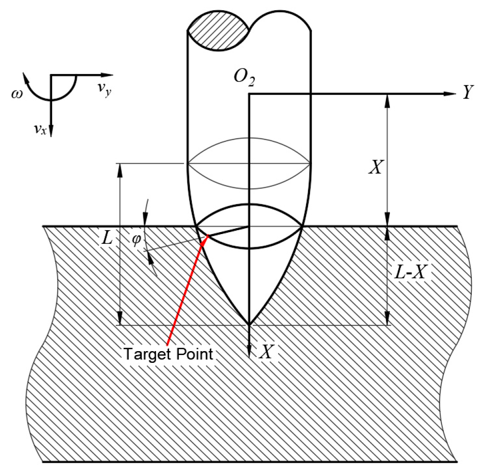
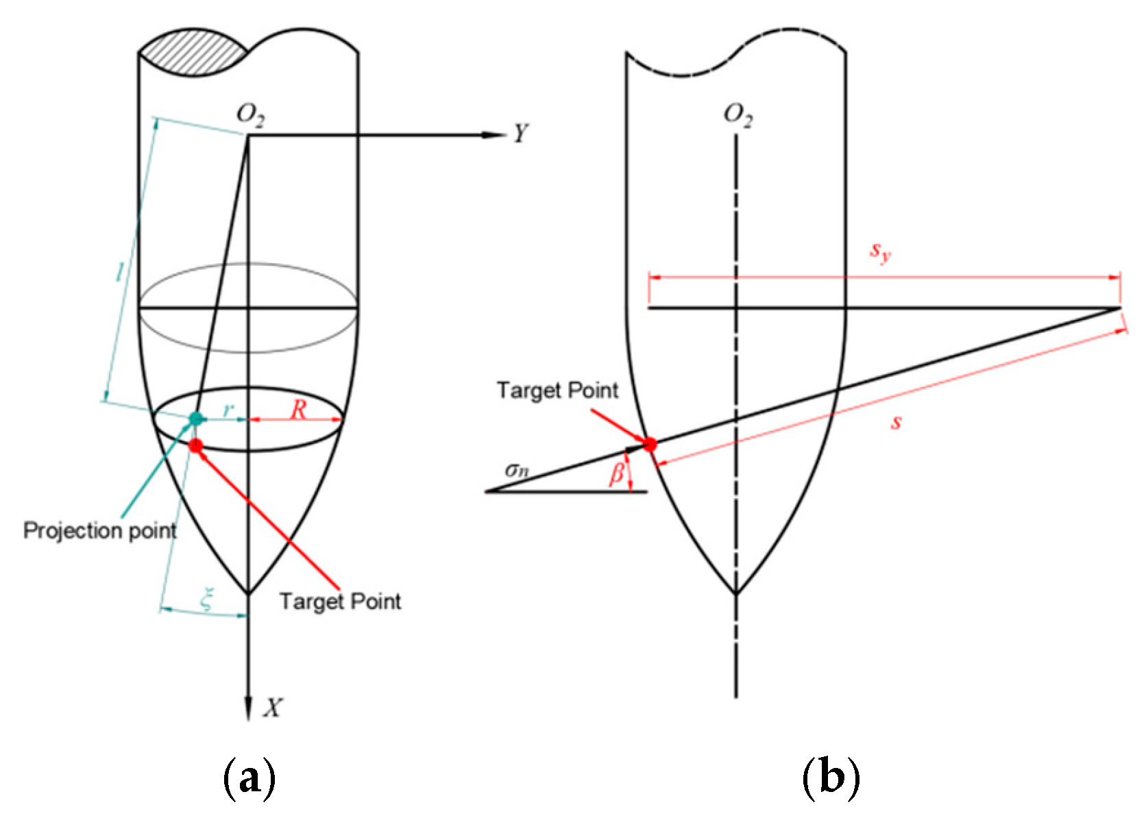
To facilitate the understanding of the physical quantities and coordinate transformations involved in the subsequent theoretical model derivation, the positional relationships of the projectile prior to penetration and the establishment of the coordinate system are illustrated in Figure 1 and Figure 2.
The assumptions adopted in this study regarding projectile penetration are consistent with those proposed by Liu et al. [30], as follows:
(1)
Projectile is rigid, with no deformation or damage;
(2)
Resistance acts only on the nose of the projectile;
(3)
No rotation occurs about the projectile’s longitudinal axis during motion; only planar motion is considered;
(4)
Coarse aggregates are neglected, and the concrete is assumed to be a homogeneous and isotropic material.
Using Liu’s formulation, the velocity and resistance at any nose point (X, φ) can be computed, with Equations (1)–(3) describing them as follows:
v = v X , v Y , v Z v X = v x ω l sin ξ = v x ω r v Y = v y ω l cos ξ = v x ω X v Z = 0
v n = 2 cos ϕ v y l 2 ω s y + ω d 2 s cos ϕ 2 v x X l 2 1 2 s
d F X = σ n X l 2 R s y d X d ϕ d F Y = σ n R cos ϕ d X d ϕ d M = σ n cos ϕ X l 2 R X s y R s y d X d ϕ
where X is the axial coordinate of the point on the projectile nose surface, and vx, vy, and ω denote the axial velocity, tangential velocity, and angular velocity of the projectile, respectively. ξ is the angle between the line l connecting the projection of the target point onto the O2XY plane and the projectile’s centroid, and the positive direction of the X-axis (see Figure 3) and ξ = arctan r / X , l = X 2 + r 2 1 / 2 . r is the radial distance from the projection point to the center of the circular cross-section containing the target point, r = R cos ϕ . R is the radius of the circular cross-section at the target point, R = d / 2 + s y s , s y = s 2 X l 2 2 1 / 2 . s is the local radius of curvature of the projectile nose surface, cos β = s y / s , and β is the angle between the surface normal vector at the target point and the radial direction of the projectile body.
Warren et al. [40,41] accounted for free-surface proximity via correction coefficients (Equations (4) and (5)).
σ n a = 2 ρ 0 v n 2 1 α λ 4 1 α λ 1 τ λ + 2 E 3 τ α λ 3 2 τ 3 1 b d * 3 + 2 ρ 0 v n 2 α λ α λ 1 3 τ 2 E 1 3 1 4 α λ α λ 4 3 τ 2 E 4 3 a d * + 1 4 a d * 4 + τ λ
f d * , a , v n = σ n a σ n a d * d * b 0 d * < b
where a, b, and d* represent the outer radius of the concrete cavity, the radius of the plastic response zone, and the distance from the target’s free surface to the projectile axis, respectively (see Figure 4). d* can be determined directly from geometric relations. b = R 2 E / 3 τ 1 / 3 , vn is the cavity expansion velocity, E is the elastic modulus of concrete, ρ0 is the initial density of the concrete, τ denotes the cohesion under the Mohr–Coulomb failure criterion, given by τ = 3 λ f c / 3 , and fc is the uniaxial compressive strength of the concrete. λ is the pressure hardening coefficient; for concrete, λ = 0.67, α is a material parameter defined as α = 6⁄(3 + 2λ).
Shanyu [42] argued that concrete exhibits lower brittleness compared to rock materials. As a result, when the free surface lies within the plastic response zone, the radial stress acting on the projectile surface does not drop abruptly to zero. Based on this observation, an improved free-surface attenuation coefficient suitable for concrete materials was proposed, expressed as
f d * , a , v n = σ n a σ n a d * d * b d * b σ n a d * = b σ n a d * d * < b

2.2. Dynamic Shear_Plugging Model

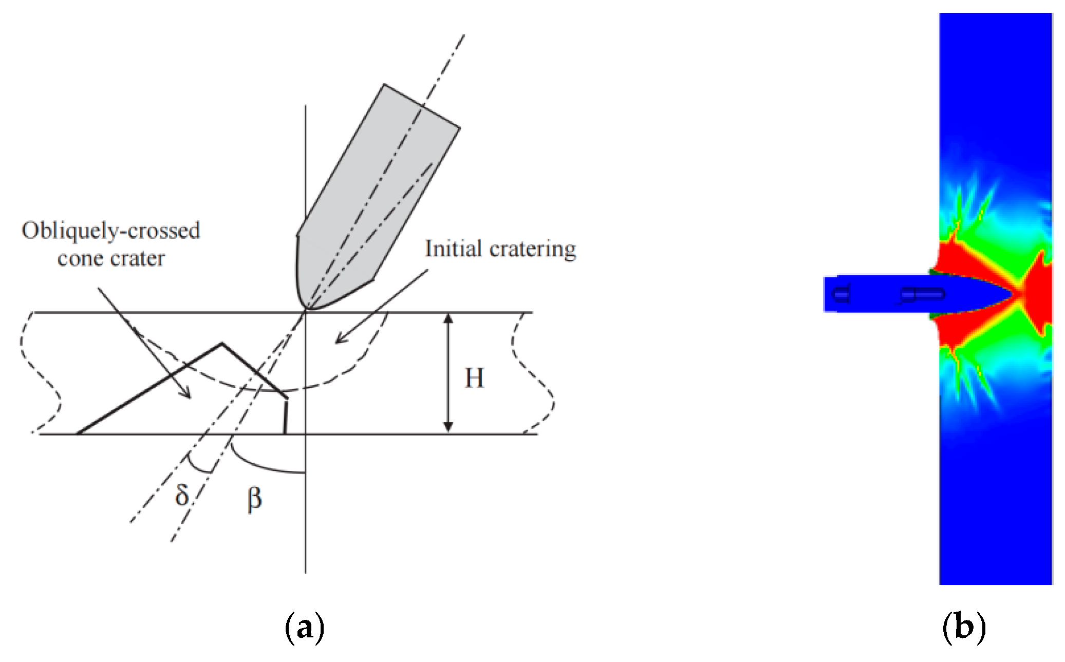
Classical models assume a frustum-shaped plug (half-cone angle ≈ 66.1°) [43], extending from the cylindrical body to the rear face (Figure 5a). However, numerical simulations reveal the initial plug is more conical (Figure 5b).
According to Duan et al. [28,29], the projectile undergoes a “secondary deflection” during the shear_plugging phase, which leads to a gradual correction of its attitude angle. Based on this analysis, the attitude angle is expected to decrease as the projectile exits the target. However, comparative analysis of penetration tests into thin concrete targets reveals that the projectile’s attitude angle continues to increase after exiting the target (see Figure 6). The red outlines in the figure represent the external profiles of the projectile at different moments, captured by high-speed photography.). Therefore, applying this model to thin_target penetration scenarios results in significant errors in the predicted post-exit attitude angle.
The underlying reason lies in the penetration mechanics specific to thin concrete targets. When the initial shear plug begins to form, the projectile nose has often not yet fully entered the target. This results in a coupling between crater formation and shear plugging. At this stage, the cratering effect tends to increase the projectile’s attitude angle, while the shear plugging effect suppresses its growth. Therefore, analyzing the shear plugging phase in isolation leads to significant inaccuracies.
To address this issue, a dynamic shear plugging model incorporating crater–plugging coupling is proposed to characterize the failure process of thin concrete targets under penetration. Under such coupled conditions, the shear plugging criterion originally proposed by Li becomes less applicable. Instead, this study develops a description of the dynamic plugging process based on experimental observations.
The following assumptions are made for the dynamic shear plugging mechanism:
(1)
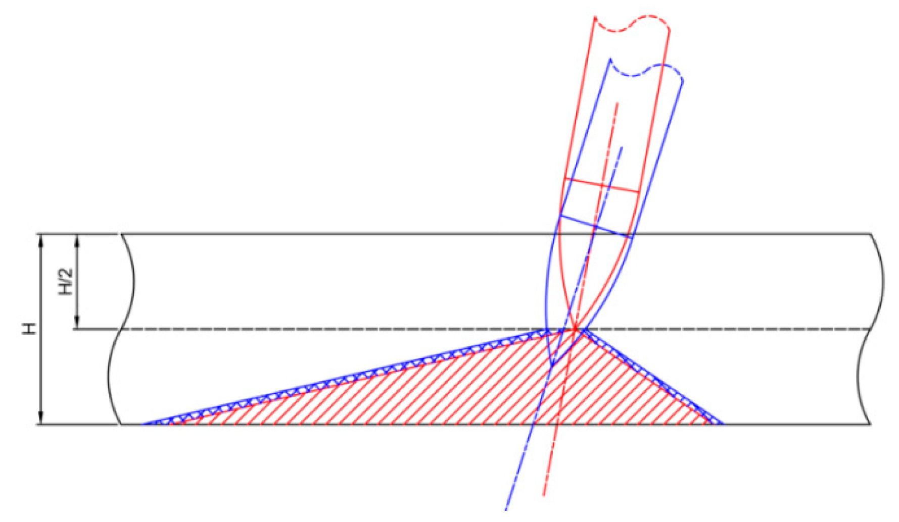
Based on the findings of Peng et al. [44], the thickness of the shear plug formed during the penetration of thin concrete targets is approximately half the target thickness. When the projectile nose reaches mid-thickness, an initial conical shear plug is generated behind the projectile (see red region in Figure 7).
(2)
The axis of the shear plug is colinear with the projectile axis. The half-cone angle of the subsequent shear plug remains consistent with that of the initial plug, and their central axes are parallel.
(3)
During penetration, the initial shear plug remains relatively intact and continues to exert resistance on the projectile. However, newly generated shear zones (see blue region in Figure 7), which peel off in layers, no longer resist the projectile. Once the projectile nose reaches the rear surface of the target, the plug is fully fractured and ceases to offer resistance.
(4)
The failure surface during the shear-plugging process originates at the intersection between the projectile nose surface and the mid-plane of the target. It propagates toward the rear surface while maintaining a constant half-cone angle.
Similarly, during the dynamic shear_plugging phase, the differential surface force method is continuously applied to calculate the local surface stresses on the projectile nose. The effect of the free surface is also considered. However, as the shear_plugging process evolves, the position of the target’s free surface changes dynamically. Therefore, iterative updates are required in the computational implementation to account for these variations.The parameters a and d*, which are used to calculate the effects of the free surface of the plug on the external surface of the projectile head as it enters the plug, are indicated by the black lines in Figure 8. The surface of the projectile located at the front part of the target, as shown in the bright green section of Figure 8, is also subject to calculation.

2.3. Model Implementation and Numerical Solution

The surface force acting on the projectile, derived from cavity expansion theory, can be expressed as follows:
σ n = A 1 f c + A 2 v n ρ 0 f c + A 3 ρ 0 v n 2
According to the work of Feng [45], the following relation holds for ordinary concrete:
A 1 = 90 + 9.769 f c ρ 0 / ρ g 0.0218 f c ρ 0 / ρ g 2 / f c A 2 = 1.15 A 3 = 0.876
In Equation (8), ρg denotes the compacted density of concrete, taken as 2680 kg/m3, and fc is in units of MPa, while the output from Equation (7) is expressed in Pascals (Pa). By combining Equations (2), (4), (6), (7), and (8), the local stress at any point on the projectile nose can be calculated. Substituting this stress into Equation (3) yields the resistance force and moment acting on the corresponding surface element.
A computational program is developed to solve the penetration process based on this framework. By recording the projectile velocity, attitude angle, and other key parameters at each time step, the full evolution history of both the attitude angle and angle of attack throughout the penetration can be obtained. The primary criterion for determining the penetration stage of the projectile is the spatial position of the projectile nose within the target plate, which is defined by two key parameters: the penetration depth of the projectile nose, dₚ, and the projectile attitude angle, Ψ. The calculation process is illustrated in Figure 9.
It is important to note that the coordinate system used in the computation is fixed with respect to the projectile’s centroid and longitudinal axis. Therefore, at each computational step, the expressions and coordinates of key surfaces and points on the target must be updated accordingly.

3. Experimental Study and Model Validation

To validate the accuracy of the proposed theoretical model, a series of verification experiments was designed in which 30 mm projectiles penetrated through thin concrete targets under varying angles of attack. A specialized eccentric sabot technique was employed to generate stable angles of attack using a smoothbore gun platform. By precisely controlling the mass of the propellant charge and the initial eccentric angle of the sabot, both the impact velocity and the initial angle of attack of the projectile were finely tuned.

3.1. Experimental Design

To assess the applicability of the theoretical model under different impact velocities, initial angles of attack, and concrete target thicknesses, the following experimental scheme, as shown in Table 1, was developed.
The projectiles used in the experiments were calibrated for mass-related properties prior to testing. The measured mass and centroid parameters are summarized in Table 2.
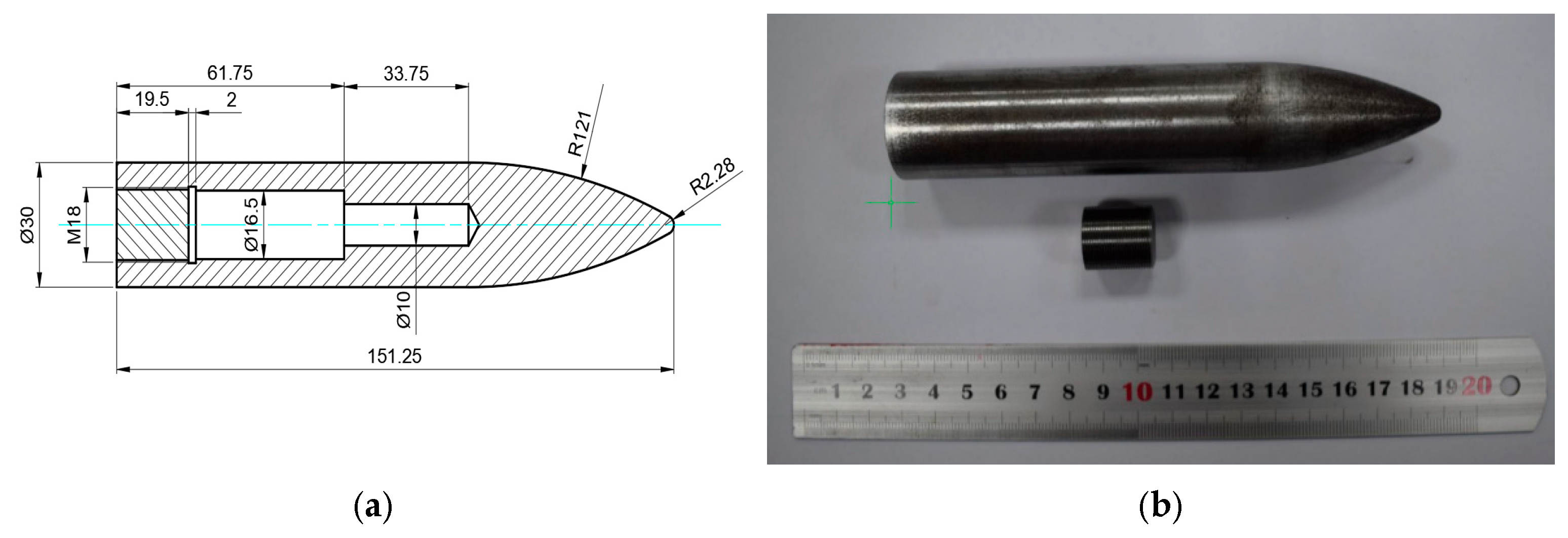
The geometry and physical appearance of the projectile used in the experiments are shown in Figure 10. The target plate was made of C35-grade concrete, with a measured density of 2270 kg/m3. Prior to testing, its uniaxial compressive strength was determined to be 27 MPa.

3.2. Measurement System

Determining the flight attitude of the warhead during experiments has long been a focal point of interest among researchers. Warrn et al. [16] deployed an orthogonal X-ray system in front of the target to capture the projectile’s projections on two perpendicular planes using radiographic film. Although this method offers high measurement accuracy, it imposes stringent requirements on the experimental site and is often cost-prohibitive. Based on the principle of mirror imaging, this study derives a set of analytical formulas to compute the projectile’s three-dimensional attitude angles by recording the spatial coordinates of key positions captured by the high-speed imaging system.
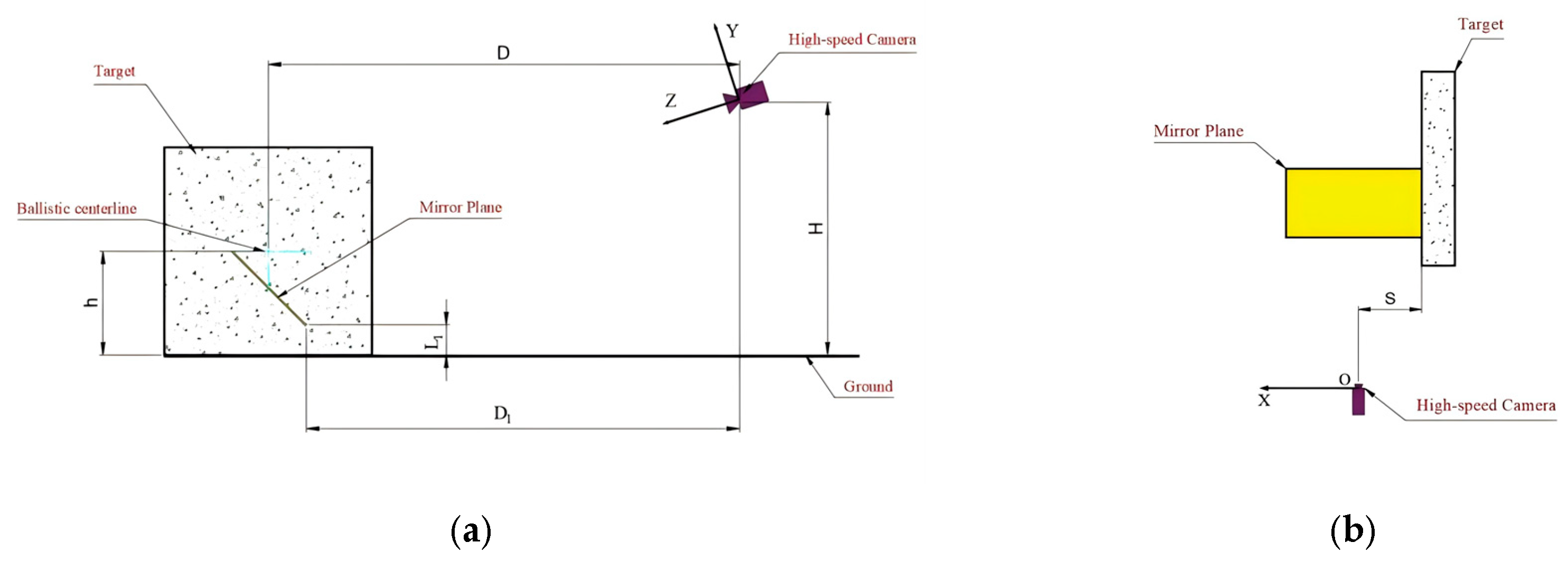
Figure 11 illustrates the spatial arrangement of the high-speed imaging system, target plate, and planar mirror. The mirror is inclined at an angle of π/4 relative to the horizontal ground. The high-speed camera is positioned at a horizontal distance D from the projectile trajectory axis, D1 from the front edge of the mirror, and S from the target plate. The vertical height of the high-speed camera is denoted as H, the trajectory axis height as h, and the vertical height of the lower edge of the mirror as L1.
A three-dimensional Cartesian coordinate system is established with the high-speed camera as the origin. The X-axis is defined as perpendicular to and outward from the target surface, while the Z-axis is perpendicular to the projectile’s trajectory plane, extending from the origin.
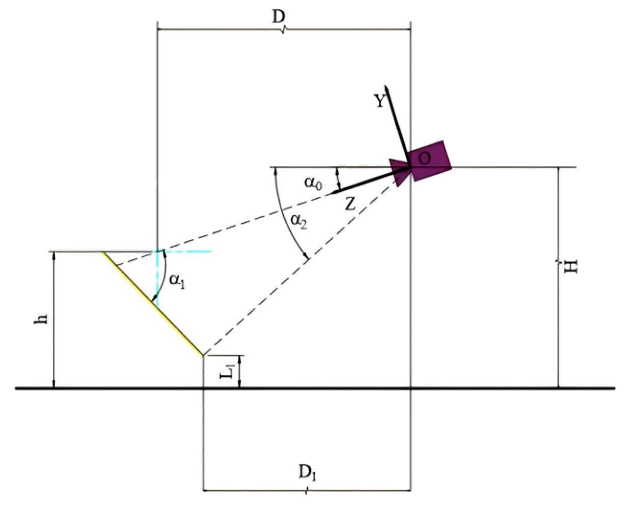
As shown in Figure 12, the angle between the Z-axis and the horizontal direction is denoted as α0, the angle between the mirror surface and the horizontal axis is denoted as π/4, and the angle between the mirror and the Z-axis is represented by α1. Based on the geometric relationships illustrated in the figure, the following equations can be derived:
α 0 = arctan H h D
α 1 = α 0 + π / 4
α 2 = arctan H L 1 D 1
Assume that the angle between the projectile’s longitudinal axis and the X-axis is denoted as θ0. The projection of the projectile axis onto the XOY plane forms an angle θ1 with the X-axis. The projection of the mirrored projectile axis (as seen in the horizontal mirror) onto the XOY plane forms an angle θ3 with the X-axis. Additionally, the projection of the projectile axis onto the XOZ plane forms an angle θ2 with the X-axis, as illustrated in Figure 13.
Based on this, the coordinate of the center point at the base of the projectile can be assumed as (x0,y0,z0), and the projectile length is denoted as l. The coordinate of the projectile tip can then be calculated accordingly, (x1,y1,z1) = (x0 − lcosθ2cosθ1, y0 + lcosθ2sinθ1, z0 + lsinθ1). Let the distance from the origin to the lower edge of the mirror be S1; based on the spatial configuration, the following relationship can be established:
S 1 = H L 1 2 + D 1 2
Let β = α 2 α 0 ; then, the spatial equation of the mirror surface can be expressed as
y = S 1 sin β z = S 1 cos β
The analytical expression of the mirror surface in three-dimensional space is given by
y + S 1 sin β z S 1 cos β = tan α 1 = 1 + tan α 0 1 tan α 0
By converting Equation (14) into the standard form of a plane equation, the coefficients of each term are obtained as follows:
a = 0 b = 1 tan α 0 c = ( 1 + tan α 0 ) d = S 1 sin β + cos β + tan α 0 cos β sin β
Based on the method for computing the coordinates of a point’s mirror image with respect to a plane, and by eliminating the term corresponding to a = 0, the mirrored coordinates of the projectile base center x 0 , y 0 , z 0 and the projectile tip x 1 , y 1 , z 1 can be obtained as follows:
x 0 , y 0 , z 0 = x 0 , b 2 y 0 + c 2 y 0 2 b c z 0 2 b d b 2 + c 2 , b 2 z 0 c 2 z 0 2 b c y 0 2 c d b 2 + c 2
x 1 , y 1 , z 1 = x 1 , b 2 y 1 + c 2 y 1 2 b c z 1 2 b d b 2 + c 2 , b 2 z 1 b 2 z 1 2 b c y 1 2 c d b 2 + c 2
By solving Equations (16) and (17) simultaneously, the following results are obtained:
y 1 y 0 x 1 x 0 = b c b + c tan θ 1 + 2 b c sec θ 1 tan θ 2 b 2 + c 2 = tan θ 3
In Equation (18), angles θ1 and θ3 can be directly extracted from the high-speed imaging data. As shown in Equation (18), the orientation of the projectile is independent of the coordinates of the projectile base.
By solving Equation (18), angle θ2 can be determined, which represents the angle between the projectile’s projection in the XOZ plane and the X-axis. Based on the spatial projection relationships, the final angle θ0 between the projectile’s axis and the X-axis can be obtained, satisfying the following relation:
θ 0 = arccos 1 cos 2 θ 1 + 1 cos 2 θ 2 1 0.5
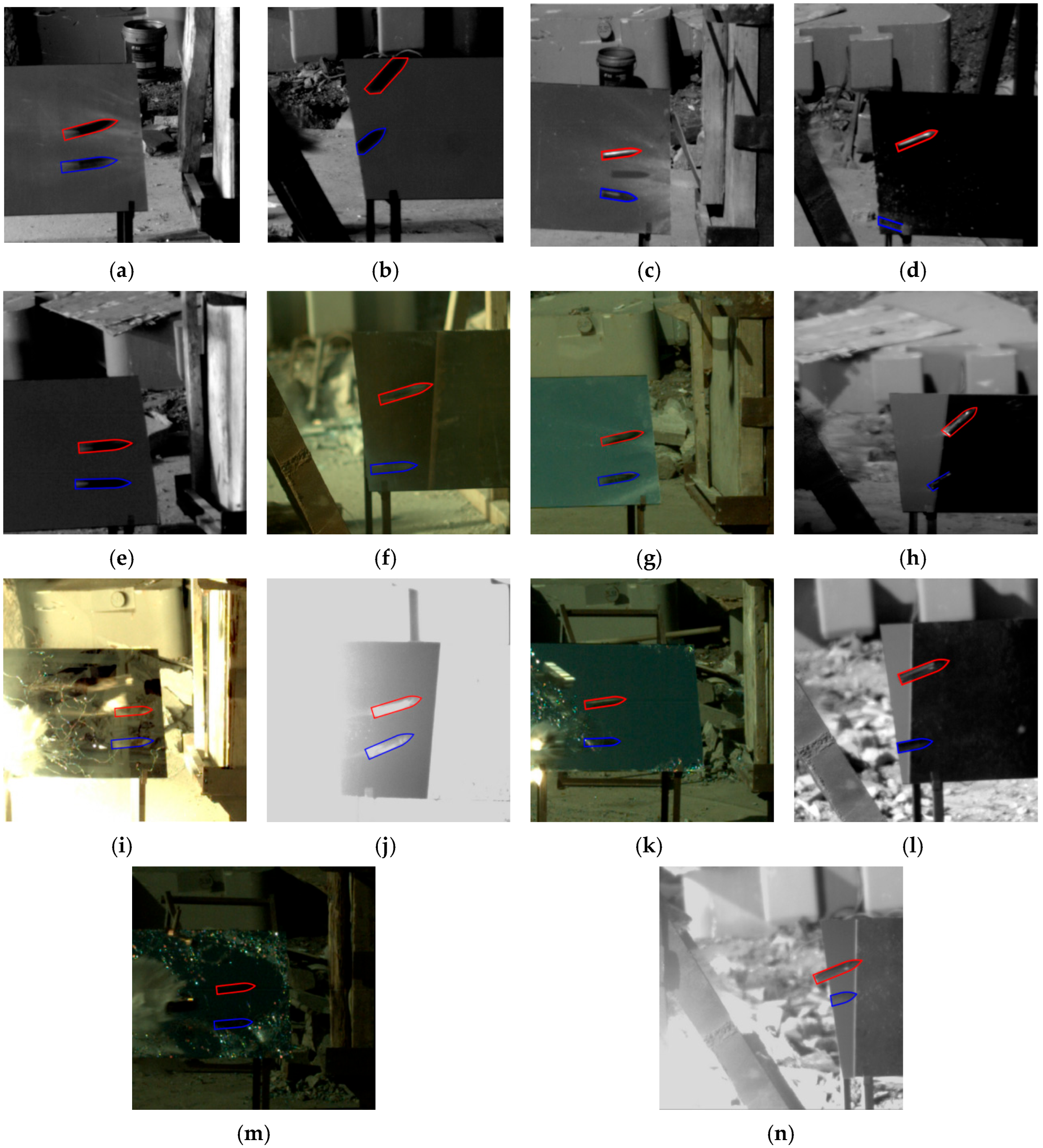
The velocity of the projectile’s center of mass is indirectly determined by analyzing the velocity of the projectile tip. It is assumed that the center of mass remains within the ballistic plane throughout the flight. The projectile’s angular orientation and spatial position can be extracted at two distinct time points from the high-speed imaging data with a time interval denoted as Δt. Then, the data can be calculated by multiplying the inter-frame interval of the high-speed camera by the number of frames between the two images. By measuring the displacement of the projectile nose between two frames, Δx, the actual displacement was obtained through proportional conversion using the pre-experiment calibration image (see Figure 14b). In Figure 14, the red outline represents the actual contour of the projectile captured by high-speed photography, while the blue indicates the mirrored contour of the projectile. The solid and dashed lines correspond to the two observed moments, respectively.
The angles between the projectile axis and the X-axis in the observation plane at these two time points, as directly obtained from the high-speed imaging system, are denoted as θ1 and θ1*. The corresponding angles between the projectile’s axis and the X-axis in the XOZ plane, as derived from the 3D attitude calculation system, are θ2 and θ2*. Let l0 represent the distance from the projectile tip to its center of mass. Based on these parameters, the horizontal velocity vx of the projectile’s center of mass can be calculated as
v x = Δ x l 0 cos θ 2 * cos θ 1 * cos θ 2 cos θ 1 Δ t

3.3. Results and Model Validation

A total of seven penetration experiments were conducted. The horizontal velocity components of the projectile are defined as vx, and the angle between the projectile axis and the horizontal direction is defined as the attitude angle Ψ. For specimens #1* and #6*, where the projectile nose was visually indistinct, the distance behind the target was measured using the center point of the projectile tail instead. The experimental results are shown in Table 3.
The projectile contour is outlined using red lines, while the mirrored contour is marked in blue. Figure 15 shows the projectile’s attitude before and after penetrating a single-layer concrete target.
Using the calibrated projectile mass properties, target strength parameters, and the initial projectile–target configuration as input conditions, the projectile velocity and attitude angle at the observation location after perforating the target were calculated using the proposed theoretical model. A comparison between the theoretical predictions and experimental results is presented in Table 4.
As shown in Table 4, the maximum error in the predicted projectile attitude angle is 19.7%, while the maximum error in the horizontal velocity is 15.0%—both within 20%. Using the same initial parameters, Duan’s theory and Liu’s theory were applied to compute the horizontal velocity and attitude angle of the projectile at the observation point. The post-impact attitude angle and horizontal velocity are summarized in Table 5.
A comparison reveals that the difference in post-impact horizontal velocity of the projectile is not significant. Therefore, only the post-impact attitude angle is subjected to further error analysis here.
Figure 16 Comparison of projectile post-impact attitude angles predicted by the present model, Duan’s model, and Liu’s model with experimental data.
As shown in Figure 16, the post-impact attitude angles of the projectile predicted by Duan’s and Liu’s theories are significantly smaller than the experimental results. This discrepancy occurs because both theories treat the cavity-opening and shear-plugging stages as isolated processes. However, during thin-target penetration, the projectile nose has not fully entered the target at the onset of shear plugging, and the contact surface between the projectile nose and the target continues to evolve. This suppresses the “secondary deflection” effect during the plugging process. As a result, when the original theoretical models are applied, the predicted deflection direction of the attitude angle in the shear-plugging stage is opposite to the actual behavior, ultimately leading to an underestimated post-impact attitude angle.
The mean absolute error (MAE), root mean square error (RMSE), and mean absolute percentage error (MAPE) between the results of the three theoretical models and the experimental data are summarized in Table 6.
As shown in Table 6, the proposed theoretical model demonstrates a clear advantage over existing models in addressing thin-target penetration problems. The primary source of error between the experimental and theoretical results arises from pixel displacement in the high-speed imaging system used to measure projectile angles, which introduces a systematic error.
This indicates that the improved three-stage penetration theory proposed in this study provides reasonably accurate predictions for engineering problems involving angle-of-attack penetration of thin concrete targets.

4. Parametric Analysis of the Evolution of Projectile Attitude Angle and Angle of Attack During Penetration

4.1. Influence of the Initial Attitude Angle

Using the theoretical model developed in this study, simulations were conducted to analyze the influence of different initial attitude angles on the evolution of the projectile attitude angle and angle of attack during penetration. The projectile was assumed to impact a 100 mm_thick 27 MPa concrete target at an initial velocity of 800 m/s and an initial angle of attack (α0) of 5°. The projectile parameters were kept consistent with those used in the experiments.
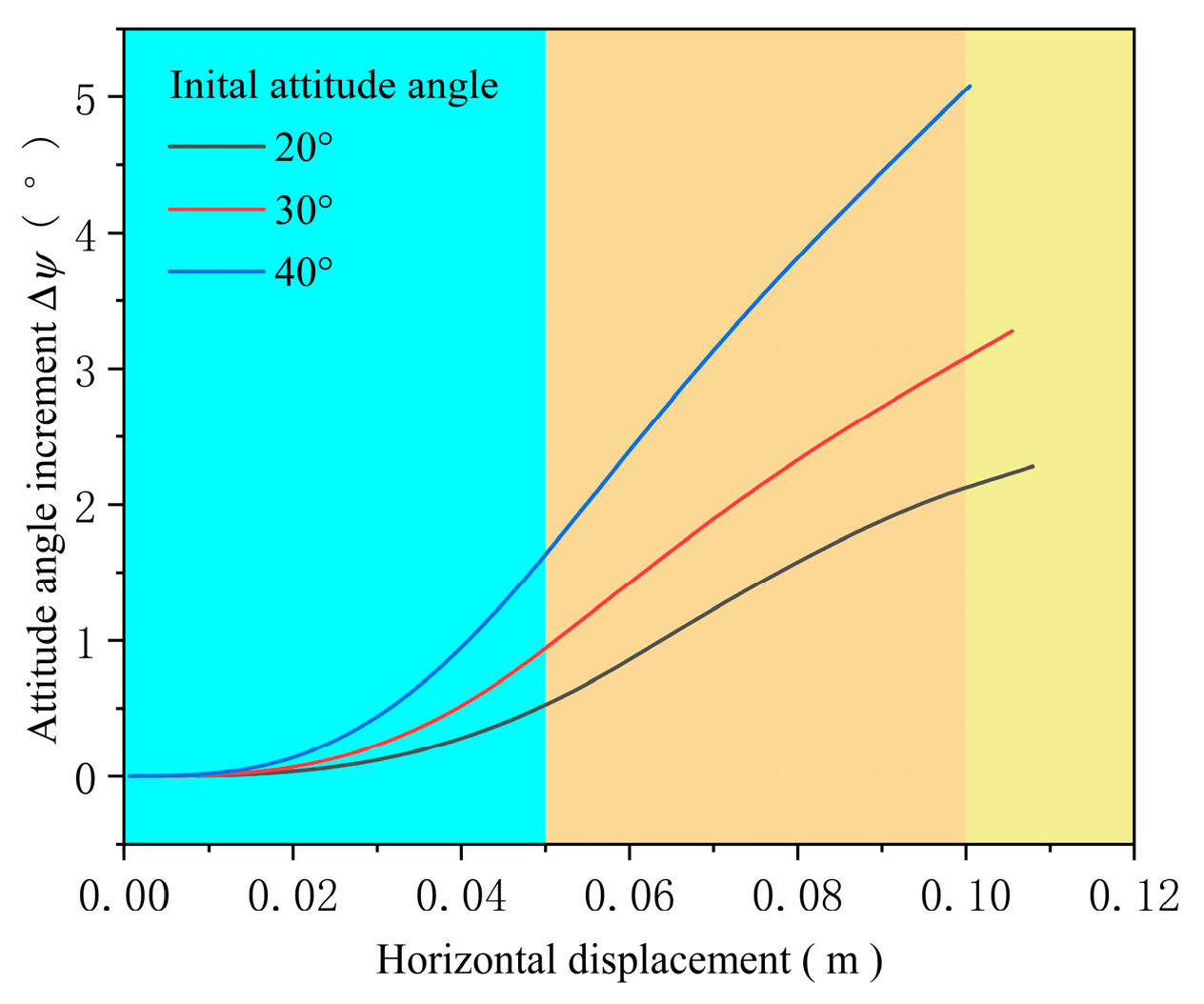
The trends in attitude angle increment (ΔΨ) and angle of attack (α) as functions of penetration depth are shown in Figure 17 and Figure 18. Based on the distinct target response characteristics, the penetration process is divided into three stages: crater formation, embedded shear plugging, and perforating shear plugging. These stages are indicated by different colors in the figures for clarity.
As shown in Figure 17, the attitude angle increment of the projectile increases with the initial attitude angle at a given penetration depth. This is attributed to the fact that a larger initial attitude angle leads to a greater asymmetry in the contact area between the projectile’s upper and lower surfaces and the target, resulting in increased non-axial forces. These non-axial forces generate a larger bending moment, which in turn induces a higher angular velocity, thereby amplifying the change in the attitude angle during penetration.
Figure 18 shows that under the combined influence of initial angle of attack and initial attitude angle, the angle of attack first decreases and then increases during penetration. A more pronounced variation in the early stages is observed as the initial attitude angle increases. By the end of penetration, the final angle of attack exhibits a positive correlation with the initial attitude angle. This phenomenon can be explained as follows: A higher initial attitude angle induces greater non-axial forces, and in the early phase of penetration, the resulting change in projectile velocity direction is more significant than the rotation induced by the bending moment. This causes the velocity vector to gradually align with the projectile axis, reducing the angle of attack. However, as penetration progresses, the angular velocity driven by the increasing bending moment begins to dominate, leading to a continuous increase in the angle of attack.

4.2. Influence of Impact Velocity

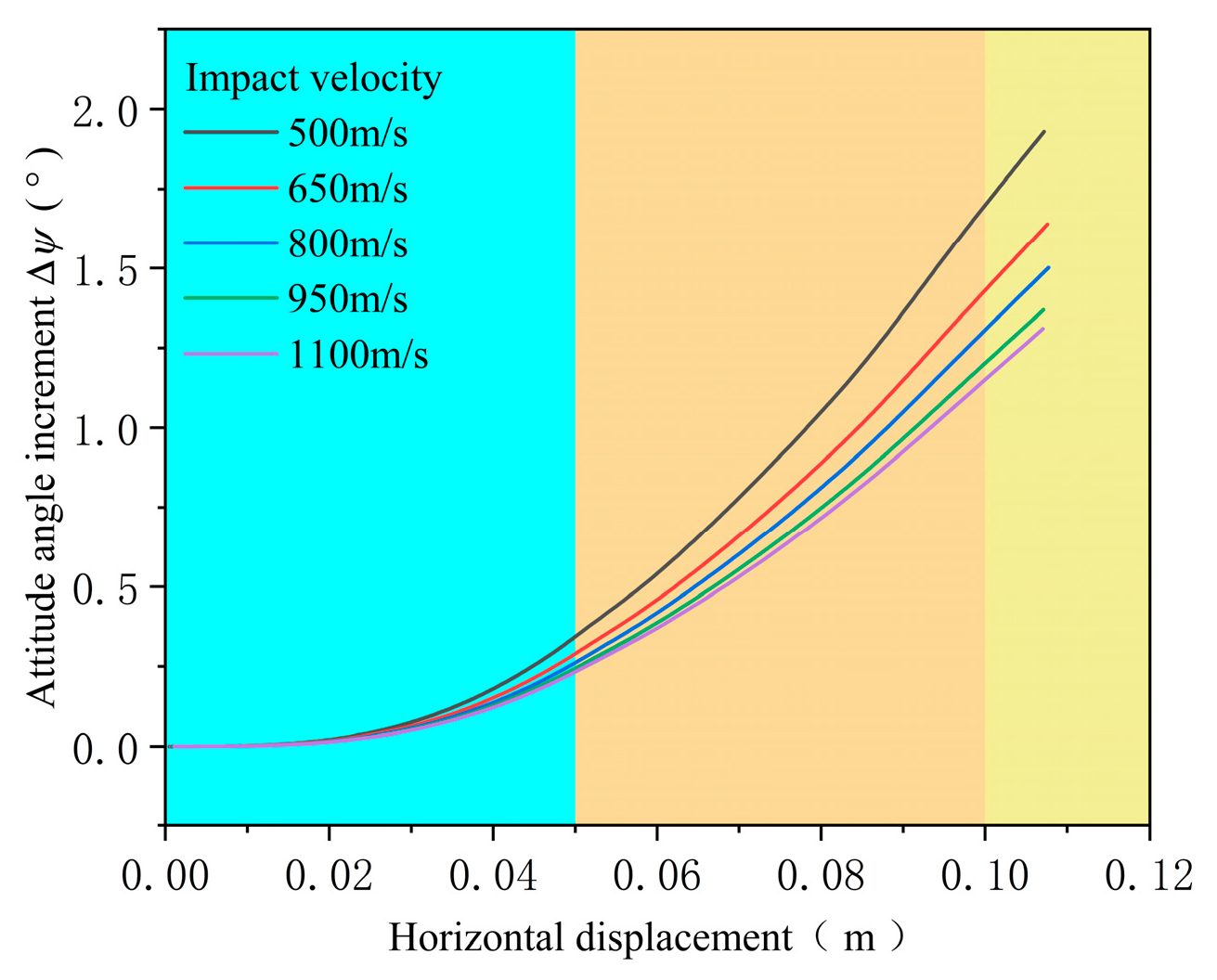
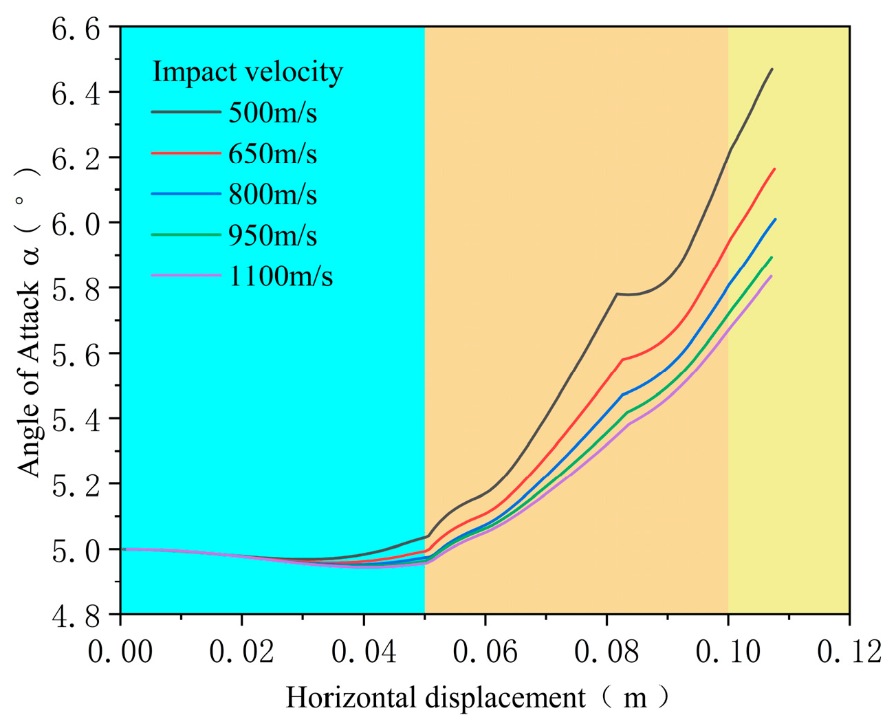
To investigate the influence of impact velocity on the projectile’s penetration attitude, the initial attitude angle (Ψ0) and initial angle of attack (α0) were both set to 5°, while the target thickness was maintained at 0.1 m. The computed evolution of the projectile’s attitude angle and angle of attack as functions of penetration depth are shown in Figure 19 and Figure 20, respectively.
As illustrated in Figure 19 and Figure 20, both the attitude angle increment and angle of attack increment decrease with increasing impact velocity at a given penetration depth. This trend can be attributed to the reduction in normal velocity components on the projectile nose surface at lower impact velocities, which leads to a corresponding decrease in normal stress. As a result, the projectile experiences a slower evolution of its motion state. However, since lower-speed projectiles require more time to reach the same penetration depth, the accumulated effect over time results in larger changes in both attitude angle and angle of attack compared to high-speed cases.
In Figure 20, the overall trend in the angle of attack shows an initial decrease during the early stage of penetration, followed by a gradual increase. When the projectile nose approaches the rear surface of the target, the increase in the angle of attack slows down due to the fracture of the plugging cone. Nevertheless, the growth in the angle of attack resumes as penetration continues. This behavior is more pronounced at lower impact velocities.
When the projectile velocity is relatively low, the resistance from the target plate is smaller, and the time rate of change of the projectile’s motion state is accordingly reduced. However, since Figure 20 is plotted with the horizontal displacement as the x-axis, a low-velocity projectile requires a longer motion time to reach the same horizontal displacement, which in turn leads to a more pronounced variation in its motion state. This explains why the curve at 500 m/s appears less smooth than the others.

4.3. Influence of Target Thickness

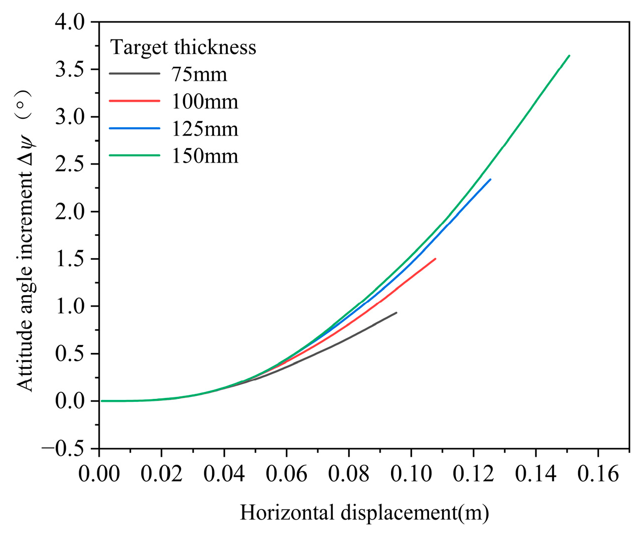
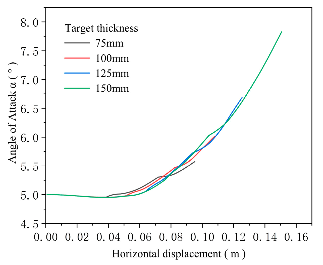
To investigate the influence of target thickness on projectile attitude deflection during penetration, the initial attitude angle (Ψ0) and angle of attack (α0) were both set to 5°, with an impact velocity of 800 m/s. The computed evolution of the projectile’s attitude angle and angle of attack as functions of penetration depth are shown in Figure 21 and Figure 22.
Due to variations in target thickness, the transition points between different penetration stages also shift. Therefore, transition regions are not marked in Figure 21 and Figure 22.
As observed from Figure 21 and Figure 22, during the early stage of penetration, the variations in projectile attitude angle increment and angle of attack are nearly identical across different target thicknesses. This is primarily because the rear surface (free surface) effect of the concrete target is not yet significant. However, as penetration progresses, thinner targets experience shear plugging earlier on, which reduces both the resistance and bending moment acting on the projectile. Consequently, the rate of change in the attitude angle decreases, and the final attitude angle at a given penetration depth becomes smaller for thinner targets compared to thicker ones.
Further analysis of the curves in Figure 22 reveals that the angle of attack gradually increases once shear plugging occurs. As the projectile nose approaches the rear surface of the target, the growth rate of the angle of attack slows down due to partial unloading. When the nose tip exits the rear surface, the angle of attack begins to increase again. Overall, the four curves collectively demonstrate that a thicker target results in a greater angle of attack at the moment of projectile exit.
It is worth emphasizing that with increasing target thickness, the target transitions from a thin to a medium-thick regime. Based on the assumption of this study, once the target thickness exceeds twice the projectile nose length, the target is no longer considered thin. Accordingly, when the thickness reaches 150 mm, the extension of the tunneling segment mitigates the projectile’s deflection effect.

4.4. Combined Influence of Multiple Parameters

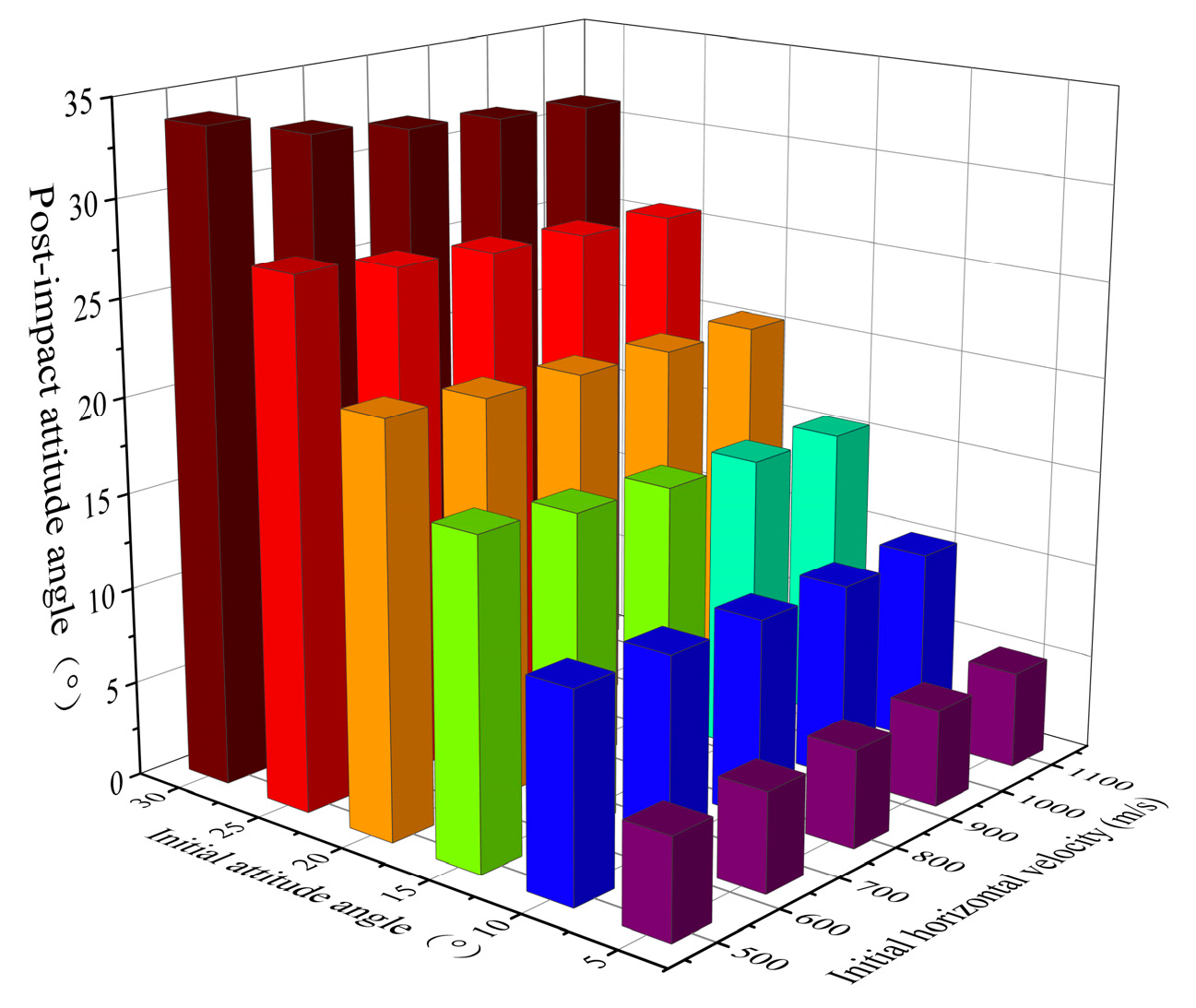
It should be emphasized that the fundamental assumption of this study is that the projectile remains undeformed during penetration. Consequently, the proposed theoretical model is not applicable to the penetration of thin concrete targets under high-velocity impact conditions or in the case of high-strength concrete. For conventional concrete targets, the variation in uniaxial compressive strength is relatively limited, and the differences in calculated penetration and perforation outcomes across different concrete strengths are correspondingly minor. Therefore, in the multi-factor analysis, variations in concrete strength are not considered, and the investigation primarily focuses on the influence of the projectile’s initial attitude angle and horizontal velocity. The relationship between the calculated post-impact attitude angle and the initial conditions is illustrated in Figure 23.
As illustrated in Figure 23, when the velocity remains constant, the post-impact attitude angle of the projectile increases with the initial attitude angle, indicating a direct correlation between the two parameters. Conversely, for a given initial attitude angle, the post-impact attitude angle decreases as the initial horizontal velocity increases. This behavior suggests that a larger initial attitude angle enhances the non-axial force acting on the projectile, thereby amplifying its deflection effect. However, increasing the initial horizontal velocity shortens the interaction time between the projectile and the target, which weakens the cumulative influence of the non-axial force. As a result, higher velocities effectively mitigate the deflection, leading to a reduction in the post-impact attitude angle.

5. Conclusions

Based on the classical three-stage penetration model, this study introduces a dynamic shear plugging mechanism to resolve the directional reversal of projectile tail deflection predicted by the original model for targets with thicknesses around five calibers. The modified model demonstrates good agreement with experimental results. The main conclusions are as follows:
(1)
For rigid projectiles penetrating thin concrete targets—especially when the target thickness is less than twice the projectile nose length—the shear plugging stage initiates before the cavity formation phase is fully completed. Treating cavity formation and shear plugging as isolated processes can lead to significant errors in predicting projectile deflection trends. By introducing a dynamic shear plugging stage, the proposed model accurately captures the evolution of projectile attitude angle during penetration.
(2)
Application of the proposed theoretical model to the penetration of a 30 mm projectile with an angle of attack into concrete with a uniaxial compressive strength of 27 MPa yielded a maximum error of 15% in post-impact velocity and 19.7% in post-impact attitude angle relative to the experimental results. These accuracies demonstrate a higher consistency with experimental observations than those obtained from existing theoretical models.
(3)
When the projectile’s velocity vector lies between the projectile axis and the normal vector of the target’s front face, the angle of attack tends to decrease during the early phase of penetration. This decreasing trend becomes more pronounced as the initial attitude angle increases. However, both the final attitude angle and angle of attack upon target exit increase with higher initial attitude angles.
(4)
The impact velocity of the projectile influences the evolution of its attitude and angle of attack during concrete target penetration. Although a lower impact velocity reduces the normal velocity component and thus the local stress on the projectile nose surface, it also increases the time required to reach a given penetration depth. As a result, both the final attitude angle and angle of attack at exit decrease as impact velocity increases.
(5)
During the early stage of penetration into concrete targets of varying thicknesses, the effect of the rear free surface is negligible, and the initial resistance remains consistent across cases. Consequently, the evolution of the projectile attitude and angle of attack is initially similar. Once shear plugging begins, the angle of attack increases more rapidly, followed by a decrease in the rate of growth. Eventually, the projectile is no longer subjected to resistance from the target and rotates at a constant angular velocity, resulting in a constant rate of increase in the angle of attack per unit time. Both the final attitude angle and angle of attack increase with target thickness.
The findings of this study not only enhance the theoretical understanding of projectile attitude evolution under angle-of-attack penetration but also open avenues for practical applications. The proposed dynamic shear-plugging model provides a reliable tool for the design and optimization of thin and multi-layered concrete protective structures, particularly in scenarios where cumulative deflection significantly influences structural performance. The framework can be further applied to performance-based design approaches for urban infrastructure protection, underground facilities, and military fortifications.
Beyond protective design, the unified description of projectile velocity and attitude dynamics has implications for trajectory correction studies, munition effectiveness evaluation, and target vulnerability assessment. By combining experimental validation, numerical simulation, and theoretical modeling, the proposed framework can serve as a foundation for developing hybrid prediction tools that balance accuracy and computational efficiency, thus providing broad value for both academic research and engineering practice.
Although the present theoretical model achieves closer agreement with experimental results compared to existing models, it is essentially derived from them and thus inherits several of their limitations. First, the model cannot be applied to penetration problems involving high-velocity impacts or high-strength concrete. Second, it neglects the friction between the projectile and the concrete during penetration, leading to an underestimation of the forces acting on the projectile. Third, the influence of the meso-scale constituents of concrete is ignored, which may introduce errors in describing the trajectory deflection process. Fourth, the assumption that the central axis of the shear plug coincides with the projectile axis during plug formation reduces the accuracy of force characterization in dynamic plugging. Moreover, the model relies on Peng’s experimental finding that the plug thickness in thin targets is half of the target thickness, which lacks a clear mechanistic explanation and therefore limits the generality of the model. Finally, in the experimental validation, the limited number of tests prevented a systematic verification of the universality of the model.
Based on these limitations, the following future work will be pursued:
(1)
Conduct meso-scale numerical simulations of oblique projectile penetration into concrete to investigate the influence of aggregate on projectile attitude evolution.
(2)
Develop a theoretical study on the shear-plugging mechanism of concrete, aiming to explore the dynamic process of plug formation and improve the description of dynamic plugging behavior.
(3)
Carry out additional experimental studies on projectile penetration with an angle of attack into thin concrete targets of different strengths, in order to verify the universality of the proposed theoretical model.
(4)
Perform projectile penetration experiments equipped with onboard sensors to record acceleration histories during the penetration process, thereby enabling continuous refinement of the theoretical model.

Author Contributions

Conceptualization, W.L. and Z.T.; methodology, Z.T.; software, Z.T.; validation, J.X.; formal analysis, J.Y.; writing—original draft preparation, Z.T. and J.Y.; writing—review and editing, W.Z. All authors have read and agreed to the published version of the manuscript.

Funding

This research received no external funding.

Data Availability Statement

The original contributions presented in this study are included in the article. Further inquiries can be directed to the corresponding author.

Conflicts of Interest

Author Jihua Yan was employed by Northern Tool Company Ltd. The remaining authors declare that the research was conducted in the absence of any commercial or financial relationships that could be construed as a potential conflict of interest.

References

  1. Liu, R.; He, M.; Ren, H.; Shi, P. Effect of Attack Angle on a Projectile’s Penetration. Trans. Beijing Inst. Technol. 2003, 23, 26–29. [Google Scholar] [CrossRef]
  2. Li, X.; Liu, Y.; Yan, J.; Zhang, K. High-speed penetration of ogive-nose projectiles into thick concrete targets: Tests and a projectile nose evolution model. Def. Technol. 2023, 19, 1521–1532. [Google Scholar] [CrossRef]
  3. Hála, P.; Hurtig, K.; Řídký, R.; Šejnoha, M. Resistance of high-performance concrete panels with dispersed fiber reinforcement to oblique-angle projectile impact. J. Mater. Civ. Eng. 2025, 37, 04024001. [Google Scholar] [CrossRef]
  4. Yang, Z.; Lv, Z.; Wu, B. Comparative research on depth empirical formula of projectile with attack angle oblique penetration into concrete. J. Sichuan Ordnance 2014, 1, 37–40. [Google Scholar] [CrossRef]
  5. Li, P.; Zhang, X.; Liu, C.; Wei, H.; Liu, J.; Deng, Y. Study on the Influence of Attack Angle and Incident Angle on Ballistic Characteristics of Projectiles Penetration into Thin Concrete Targets. Explos. Shock. Waves 2022, 42, 113302. [Google Scholar] [CrossRef]
  6. Chen, W.; Zhang, Y.; Guo, Z.; Zou, H. Penetration of Rigid Projectile into Concrete Target with Effect of Attack Angle: Theory and Experiment. Int. J. Struct. Stab. Dyn. 2017, 17, 1750080. [Google Scholar] [CrossRef]
  7. Jiang, X.; Li, Q.; Yin, X.; Xu, S. Effects of Steel Fiber and Target Thickness on the Penetration Resistance of UHPC under High Velocity Small Projectile Impact Loading. Cem. Concr. Compos. 2023, 140, 105064. [Google Scholar] [CrossRef]
  8. Wu, Y.; Tao, X.; Liu, Y.; Zhang, Q.; Xue, Y. Analysis on Deflection of Projectile Penetrating into Composite Concrete Targets. Materials 2022, 15, 7871. [Google Scholar] [CrossRef]
  9. Wang, Z.; Li, Q.; Yin, J.; Wang, Z.; Li, X.; Yi, J. Research on the Factors Influencing the Process of Prefabricated Fragments Penetrating Finite Thickness Concrete. Sci. Rep. 2024, 14, 5380. [Google Scholar] [CrossRef]
  10. Xu, X.; Tao, X.; Wu, Y.; Lu, Y.; Liu, Y.; Zhang, J.; Zhang, Y. Deflection Characteristics and Influencing Factors of Projectile Oblique Impact on Concrete Targets. AIP Adv. 2024, 14, 095109. [Google Scholar] [CrossRef]
  11. Liu, S.; Zhao, J.; Cheng, F.; Yu, H.; Chen, J. Mechanical Behavior and Failure Mechanism of Rock—Concrete Composites under the Coupling Effect of Inclined Interface Angle and Ground Temperature. Symmetry 2025, 17, 52. [Google Scholar] [CrossRef]
  12. Yan, L.; Wang, D.; Xu, Y.; Liu, M. Analysis of numerical calculation methods for oblique penetration of projectiles into concrete targets. J. Phys. Conf. Ser. 2024, 2891, 052024. [Google Scholar] [CrossRef]
  13. Ma, A.; Huang, F.; Chu, Z.; Li, J. Numerical Simulation on Yawed Penetration into Concrete. Explos. Shock. Waves 2008, 28, 33–36. [Google Scholar] [CrossRef]
  14. Zhu, Z.; Shi, Q.; Wang, G.; Hu, Q.; Zhao, S. Numerical Simulation of Attack Angle to Trajectory in Oblique Penetration. J. Proj. Rocket. Missiles Guid. 2012, 32, 609–611. [Google Scholar] [CrossRef]
  15. Song, Y.; Liu, Z.; Shi, X.; Liu, F. Study on the Oblique Penetration of Kinetic Energy Projectiles Considering Incident Angle and Attack Angle. In Proceedings of the Chinese Congress of Theoretical and Applied Mechanics, Milan, Italy, 22–27 August 2021; Sichuan Aerospace System Engineering Institute: Chengdu, China, 2021. [Google Scholar]
  16. Liu, Y.; Ma, A.; Huang, F. Numerical Simulation of Oblique-Angle Penetration by Deformable Projectile into Concrete Target. Int. J. Impact Eng. 2009, 36, 438–446. [Google Scholar] [CrossRef]
  17. Jurecs, S.P.; Tabei, A. Simulation of the Effects of Angle of Attack and Projectile Contour in Damage Development in Reinforced Concrete. Designs 2021, 5, 49. [Google Scholar] [CrossRef]
  18. Shi, H.; Ma, S.; Li, F.; Wei, J.; Tang, T. The Influence of Attack Angle on Projectile Trajectory and Fuze in Oblique Penetration. J. Phys. Conf. Ser. 2021, 2029, 012023. [Google Scholar] [CrossRef]
  19. Zhang, J.; Wang, Z.; Wang, Z.; Shu, X.; Li, Q. Penetration Trajectory of Rigid Projectile in the Heterogeneous Meso-Scale Concrete Target. Adv. Struct. Eng. 2022, 25, 1469–1482. [Google Scholar] [CrossRef]
  20. Radchenko, P.A. Influence of Reinforcement and Attack Angle on the Destruction of a Concrete Barrier under a High-Speed Impact. Russ. Phys. J. 2023, 65, 2224–2230. [Google Scholar] [CrossRef]
  21. Zhang, Q.; Yuan, R.; Wang, D.; Feng, C.; Yue, J.; Sun, L. The Impact Fracture Characteristics of Concrete Slabs under Different Hammerhead Shapes, Impact Velocities and Concrete Strengths. Constr. Build. Mater. 2023, 392, 131919. [Google Scholar] [CrossRef]
  22. Dar, R.U.N.; Alagappan, P. Ballistic Evaluation of Reinforced Concrete Panel under Oblique Impact Scenarios: A Numerical Study. Struct. Concr. 2025; in press. [Google Scholar] [CrossRef]
  23. Li, X.; Zhang, J.; Rong, Y.; Wang, Z. Mesoscopic Analysis on Projectile Motion Characteristics in Oblique Penetration into Concrete. Def. Technol. 2025; in press. [Google Scholar] [CrossRef]
  24. Zhu, C.; Liu, C.; Sheng, Q.; Deng, Y.; Wang, X. Dynamic Response of Projectile and Charge during Penetration into Concrete Target with High Velocity. Lat. Am. J. Solids Struct. 2025, 22, e8546. [Google Scholar] [CrossRef]
  25. Omidian, P.; Choubdar, S.; Khaledi, R.; Najafi, H. Simplified Numerical Simulation Modeling of a Reinforced Concrete Cold Joint: Case Study of Industrial Tower Foundation. Iran. J. Sci. Technol. Trans. Civ. Eng. 2025; in press. [Google Scholar] [CrossRef]
  26. Rosenberg, Z.; Dekel, E.; Vayig, Y.; Kositski, R.; Malka-Markovitz, A. Penetration Mechanics of Rigid Projectiles Impacting Metallic and Concrete Targets—A Summary of Our Work. Int. J. Prot. Struct. 2025, 16, 566–590. [Google Scholar] [CrossRef]
  27. Chen, X.W.; Fan, S.C.; Li, Q.M. Oblique and normal perforation of concrete targets by a rigid projectile. Int. J. Impact Eng. 2004, 30, 617–637. [Google Scholar] [CrossRef]
  28. Duan, Z.; Li, S.; Ma, Z.; Zhang, X. Analytical model for attitude deflection of rigid projectile during oblique perforation of concrete targets. Explos. Shock. Waves 2019, 39, 060801. [Google Scholar] [CrossRef]
  29. Duan, Z.P.; Li, S.R.; Ma, Z.F.; Zhang, X.L. Attitude deflection of oblique perforation of concrete targets by a rigid projectile. Def. Technol. 2020, 16, 540–549. [Google Scholar] [CrossRef]
  30. Liu, H.; Huang, F.; Bai, Z.; Duan, Z. Analytical model research on penetration of rigid projectile into concrete target with oblique and attacking angle. Acta Armen. 2023, 44, 2381–2390. [Google Scholar] [CrossRef]
  31. Gao, X.; Li, Q. Trajectory Analysis of Projectile Obliquely Penetrating into Concrete Target at Attack Angle. Acta Armamentarii 2014, 35, 33–39. [Google Scholar]
  32. Xue, J.; Shen, P.; Wang, X. Engineering Calculation Model for a Projectile’s Penetrating into a Concrete Target with Attack Angle. J. Vib. Shock 2017, 36, 40–48. [Google Scholar] [CrossRef]
  33. Wang, Z.; Yang, R.; Cui, J.; Zan, S.; Fu, J.; Wang, W.; Chen, Z. Study on Ballistic Characteristics of Projectile Penetrating Concrete Target under the Combined Action of Angle of Attack and Angle of Impact. J. Proj. Rockets Missiles Guid. 2024, 44, 43–50. [Google Scholar] [CrossRef]
  34. Cho, H.; Choi, M.K.; Park, S.; Kim, M.; Han, J.; Sohn, D. Determination of Critical Ricochet Conditions for Oblique Impact of Ogive-Nosed Projectiles on Concrete Targets Using Semi-Empirical Model. Int. J. Impact Eng. 2022, 165, 104214. [Google Scholar] [CrossRef]
  35. Li, P.; Zhang, X.; Liu, C.; Deng, Y.; Deng, Y. The Three-Dimensional Trajectory Characteristics of the Elliptical Cross-Section Projectile into Concrete Target. Int. J. Impact Eng. 2025, 206, 105414. [Google Scholar] [CrossRef]
  36. Zhang, J.; Guo, M.; Zhou, S.; Ge, C.; Chen, P.; Yu, Q. Enhanced Damage Mechanism of Reinforced Concrete Targets Impacted by Reactive PELE: An Analytical Model and Experimental Validation. Def. Technol. 2024, 42, 12–30. [Google Scholar] [CrossRef]
  37. Gao, L.; Jiang, L.; Wang, X.; Gao, S.; Cui, H.; Liu, J.; Zhou, H. Expressions for Stress Concentration Factors for T-Joints of Hollow and Concrete-Filled Square Cross-Sections for In-Plane Axial and Bending Loads. Symmetry 2024, 16, 1082. [Google Scholar] [CrossRef]
  38. Li, G.; Yang, Y.; Wen, Y.; Li, J. CGSW-YOLO Enhanced YOLO Architecture for Automated Crack Detection in Concrete Structures. Symmetry 2025, 17, 890. [Google Scholar] [CrossRef]
  39. Mo, C.; Huang, J.; Huang, J.; Li, T.; Yang, Y. Prediction of Flexural Bearing Capacity of Aluminum-Alloy-Reinforced RC Beams Based on Machine Learning. Symmetry 2025, 17, 944. [Google Scholar] [CrossRef]
  40. Warren, T.L.; Poormon, K.L. Penetration of 6061-T6511 aluminum targets by ogive-nosed VAR 4340 steel projectiles at oblique angles: Experiments and simulations. Int. J. Impact Eng. 2001, 25, 993–1022. [Google Scholar] [CrossRef]
  41. Warren, T.L.; Forsten, R.; Cline, J.; Reaugh, J.E. Penetration of limestone targets by ogive-nosed VAR 4340 steel projectiles at oblique angles: Experiments and simulations. Int. J. Impact Eng. 2004, 30, 1307–1331. [Google Scholar] [CrossRef]
  42. Shan, Y. Investigation on the Mass Abrasion and Motion of the Projectile Non-Normal Penetrating into Concrete. Ph.D. Thesis, Beijing Institute of Technology, Beijing, China, 2015. (In Chinese). [Google Scholar]
  43. Dancygier, A.N. Rear face damage of normal and high-strength concrete elements caused by hard projectile impact. ACI Struct. J. 1998, 95, 291–304. [Google Scholar] [CrossRef]
  44. Peng, Y.; Wu, H.; Fang, Q.; Zhang, J. A note on the deep penetration and perforation of hard projectiles into thick targets. Int. J. Impact Eng. 2015, 78, 37–44. [Google Scholar] [CrossRef]
  45. Feng, X. A Numerical Study of the Cavity Expansion Process and its Application to Penetration Mechanics. Master’s Thesis, National University of Defense Technology, Changsha, China, 2011. (In Chinese). [Google Scholar]
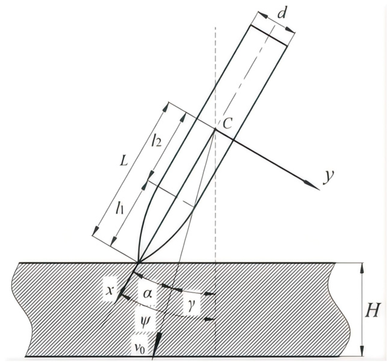
Figure 1. Penetration of an ogive-nose projectile with an angle of attack into a thin concrete target.
Symmetry 17 01572 g001
Figure 2. Schematic diagram of the projectile coordinate system.
Symmetry 17 01572 g002
Figure 3. Geometric representation of the projectile nose surface: (a) 3D view; (b) planar view.
Symmetry 17 01572 g003
Figure 4. Free-surface effects during cratering.
Symmetry 17 01572 g004
Figure 5. Shear plug formation: (a) three-stage penetration theory (without tunnel extension phase); (b) numerical simulation.
Symmetry 17 01572 g005
Figure 6. Evolution of the projectile attitude angle after exiting the target.
Symmetry 17 01572 g006
Figure 7. Schematic diagram of dynamic shear plugging during the penetration process.
Symmetry 17 01572 g007
Figure 8. Free-surface effect during dynamic shear plugging.
Symmetry 17 01572 g008
Figure 9. Computational flowchart of the theoretical model. (a) Overall computational workflow; (b) crater modeling module; (c) penetration-plugging module; (d) perforation-plugging module.
Symmetry 17 01572 g009aSymmetry 17 01572 g009b
Figure 10. The 30 mm projectile used in the experiments: (a) physical view; (b) dimensional drawing.
Symmetry 17 01572 g010
Figure 11. Configuration of the measurement system. (a) Front view of the test system; (b) top view of the test system.
Symmetry 17 01572 g011
Figure 12. Schematic of angular relationships between the projectile and coordinate axes.
Symmetry 17 01572 g012
Figure 13. Schematic of the spatial orientation of the projectile in the coordinate system. (a) Projectile spatial and mirror-image attitudes; (b) Projection of the projectile and its mirror image onto the XOY plane; (c) Projection of the projectile onto the XOZ plane.
Symmetry 17 01572 g013
Figure 14. High-speed photography images. (a) Post-processing of high-speed camera data; (b) pre-experiment calibration images.
Symmetry 17 01572 g014
Figure 15. Attitude variation in the projectile before and after perforating the concrete target. (a) #1: Pre-penetration; (b) #1: Post-penetration; (c) #2: Pre-penetration; (d) #2: Pre-penetration; (e) #3: Pre-penetration; (f) #3: Pre-penetration; (g) #4: Pre-penetration; (h) #4: Pre-penetration; (i) #5: Pre-penetration; (j) #5: Pre-penetration; (k) #6: Pre-penetration; (l) #6: Pre-penetration; (m) #7: Pre-penetration; (n) #7: Pre-penetration.
Symmetry 17 01572 g015
Figure 16. Comparison of projectile exit attitude angles predicted by the present theoretical model and existing models with experimental results.
Symmetry 17 01572 g016
Figure 17. Variation in projectile attitude angle increment with penetration depth under different initial attitude angles.
Symmetry 17 01572 g017
Figure 18. Variation in projectile angle of attack with penetration depth under different initial attitude angles.
Symmetry 17 01572 g018
Figure 19. Variation in projectile attitude angle increment with penetration depth under different initial velocities.
Symmetry 17 01572 g019
Figure 20. Variation in projectile angle of attack with penetration depth under different initial velocities.
Symmetry 17 01572 g020
Figure 21. Variation in projectile attitude angle increment with penetration depth under different target thicknesses.
Symmetry 17 01572 g021
Figure 22. Variation in projectile angle of attack with penetration depth under different target thicknesses.
Symmetry 17 01572 g022
Figure 23. Comparison of post-impact attitude angles under varying initial horizontal velocities and attitude angles.
Symmetry 17 01572 g023
Table 1. Experimental scheme for projectile penetration.
NO.Impact Velocity (m/s)Initial Angle of Attack
(°)
Target Thickness
(mm)
1#6001290
2#600675
3#900690
4#90012105
5#1200690
6#9006105
7#900675
Table 2. Measured mass and centroid parameters of the projectile.
Mass (kg)Centroid (mm)Moment of Inertia (kg·m2)
XYZX-axisY-axisZ-axis
0.5967.990.01−0.029.76 × 10−59.03 × 10−49.14 × 10−4
Table 3. Changes in projectile velocity and attitude angle before and after target perforation.
NO.Pre-Impact Horizontal Velocity,
vx0
(m/s)
Pre-Impact Attitude Angle,
Ψ0
(°)
Post-Impact Horizontal Velocity,
vx1
(m/s)
Post-Impact Attitude Angle,
Ψ1
(°)
Target Plate Thickness,
(mm)
Nose–Rear Surface Distance,
(mm)
#1*610.414.9496.247.990505.4
#2617.18.7559.924.479683.7
#3871.57.1803.215.594738.6
#4933.114.2780.451.398729.8
#51147.46.91080.525.394474.5
#6*903.96.6803.323.8105503.6
#7899.48.5820.927.579701.6
Table 4. Comparison between experimental results and theoretical predictions.
NO.Experimental ResultTheoretical ResultError
Post-Impact Attitude Angle, Ψ1e (°)Post-Impact Horizontal Velocity,
vx1e (m/s)
Post-Impact Attitude Angle Ψ1t (°)Post-Impact Horizontal Velocity,
vx1t (m/s)
ΔΨ/Ψ1eΔvx/vx1e
#1*47.9496.256.6570.518.0%15.0%
#224.4559.926.6588.58.9%5.1%
#315.5803.218.5839.719.7%4.5%
#451.3780.460.5832.217.8%6.6%
#525.31080.521.61115.4−14.5%3.2%
#6*23.8803.325.4865.86.7%7.8%
#727.5820.927.8873.81.1%6.4%
Table 5. Post-impact attitude angle and horizontal velocity of the projectile calculated using Duan’s and Liu’s theories.
NO.Duan’s Theoretical ResultLiu’s Theoretical Result
Post-Impact Attitude Angle, Ψ1D (°)Post-Impact Horizontal Velocity,
Vx1D (m/s)
Post-Impact Attitude Angle, Ψ1L (°)Post-Impact Horizontal Velocity,
Vx1L (m/s)
#1*2.4559.50.2539.4
#23.6594.62.1581.0
#33.4848.52.7833.4
#46.2867.24.3848.6
#55.31121.94.51109.0
#6*3.0880.12.4862.4
#75.6872.94.5862.5
Table 6. Statistical metrics of the post-impact attitude angle predicted by the three theoretical models.
Theoretical ModelMean Absolute Error (MAE)Root Mean Square Error (RMSE)Mean Absolute Percentage Error (MAPE)
the present model4.15.212.4%
Duan’s model26.629.384.6%
Liu’s model27.930.688.7%
Disclaimer/Publisher’s Note: The statements, opinions and data contained in all publications are solely those of the individual author(s) and contributor(s) and not of MDPI and/or the editor(s). MDPI and/or the editor(s) disclaim responsibility for any injury to people or property resulting from any ideas, methods, instructions or products referred to in the content.