Article

Parametric Analysis of Reinforced Concrete Hollow Piers Based on an Axial–Flexure–Shear Model Under Cyclic Loading and Earthquake Conditions

1
School of Architecture and Civil Engineering, Chengdu University, Chengdu 610106, China
2
School of Civil Engineering, Southwest Jiaotong University, Chengdu 610031, China
*
Author to whom correspondence should be addressed.
Symmetry 2025, 17(9), 1553; https://doi.org/10.3390/sym17091553
Submission received: 13 August 2025 / Revised: 6 September 2025 / Accepted: 13 September 2025 / Published: 17 September 2025
(This article belongs to the Section Engineering and Materials)

Abstract

To enhance the understanding of the seismic behavior of reinforced concrete (RC) hollow piers, a sensitivity analysis of design parameters is conducted. A novel analytical model named the Axial–Flexure–Shear-Interaction-Membrane-Beam-Truss-Element-Model (AFSI-MBTEM) is proposed to account for the flexure–shear coupling. To avoid size effects, three full-scale rectangular RC hollow piers are simulated and validated using the AFSI-MBTEM. Based on a benchmark model, the influence of parameters on seismic responses is explored under cyclic loading, earthquakes, and different PGAs. The AFSI-MBTEM can efficiently and accurately capture the symmetric and asymmetric hysteretic curves of RC hollow piers. The influence of parameters under cyclic loading is generally consistent with that under strong earthquakes. The aspect ratio, width-to-depth ratio, wall thickness ratio, axial load ratio, and longitudinal rebar ratio have a significant influence under cyclic loading, earthquakes, and different PGAs. The influence of stirrup ratio, concrete strength, and longitudinal rebar strength becomes clear under earthquakes, especially for residual deformation. The suggested parameter values for hollow piers are as follows: aspect ratio of 4–6, width-to-depth ratio of 1.0–2.0, wall thickness ratio of 20–40%, axial load ratio of 0.05–0.10, longitudinal rebar ratio of 1.2–2.2%, stirrup ratio of 0.8–1.2%, concrete strength of C40, and longitudinal rebar strength of 400 MPa and 500 MPa.

1. Introduction

Bridges are essential components of transportation networks, playing a vital role in supporting a nation’s economic activities [1,2]. Reinforced concrete (RC) piers are the primary structural elements of bridges, and transfer dead loads, live loads, and seismic forces from the superstructure to the foundation [3]. Specifically, RC piers are sensitive to inertial forces during an earthquake, and their failure can lead to severe damage to the entire bridge [4,5]. Compared with RC solid piers, hollow piers present multiple benefits, including reduced self-weight, lower inertial forces, and enhanced structural efficiency [6,7,8]. Owing to these advantages, hollow sections have become a prevalent choice in pier design, as they offer an economical solution without compromising stiffness and are well-suited for tall-pier bridges in mountain regions of Southwest China [9,10,11]. However, strong earthquakes frequently occur in these regions [12,13,14], and due to the cross-sectional excavation, the seismic performance of RC hollow piers has gained much attention.
Over the past decades, a large number of experiments have been conducted on RC hollow piers. Mander et al. [15] studied the effects of axial load ratio and stirrup ratio on the ductility behavior of rectangular hollow piers under cyclic loading. Experimental results show that the stirrup confinement effect is beneficial to the ductility, energy dissipation, and flexural bearing capacity of hollow piers. Quasi-static tests of reduced-scale and full-scale RC hollow piers were conducted by Yeh et al. [16,17], revealing that flexure–shear or shear failure may occur when either the stirrup ratio is less than half of that required or the aspect ratio is less than 2.5. Mo et al. [18] investigated the seismic behaviors of high-strength concrete rectangular hollow piers with different aspect ratios, stirrup ratios, and axial load ratios. Pinto et al. [19] carried out an experimental study on the seismic performance of thin-walled rectangular hollow piers, where the wall thickness-to-width ratio in the lateral loading direction was 0.153. Calvi et al. [20] focused on the damage development and collapse modes of rectangular hollow piers with inadequate stirrup ratios and insufficient lap splice lengths. Cassese et al. [21] conducted 1:4 scale tests on hollow rectangular bridge piers, revealing flexure–shear failure when the aspect ratio is smaller than 3.0. Han et al. [22] investigated the seismic behavior of rectangular hollow piers under bidirectional coupled loading, and found that piers are more prone to damage under such loading. For circular hollow piers, Zahn [23], Yeh [24], and Cassese et al. [25] studied the axial load ratio, flexural strength, and shear behavior, respectively. Moreover, the seismic performance of rounded rectangular hollow piers for railway bridges with different stirrup ratios and axial load ratios has been investigated under cyclic loading [8,26] and shaking table tests [6]. These experiments clearly reveal the influence of design parameters on the damage evolution, failure mode, ductility, and energy dissipation of RC hollow piers. However, due to the high cost of tests, reduced-scale hollow piers are mostly used, and the scope of parameters studied has been limited. Thus, some researchers have adopted finite element methods to simulate hollow piers, enabling a better understanding of their seismic performance. For example, the fiber-based beam-column element model provides good analysis accuracy and efficiency for flexure-dominant hollow piers [27], but it cannot simulate the flexure–shear interaction that is obviously observed in such hollow piers [15,16,17,18,19,20,21,22,23,24,25,26]. The software ABAQUS 2024 captures the failure modes of hollow piers [28] and the effects of axial load ratio and aspect ratio [29], but the use of solid elements is time-consuming. To address low computational efficiency, shear springs are used at the ends of fiber-based elements to account for the shear effect in RC hollow piers [30,31], but this approach is actually inconsistent with the real physical mechanism.
Based on the above review, it can be concluded that there are some shortcomings in the existing research. First, more systematic parametric analyses are deserved based on full-scale hollow piers to provide more specific conclusions. Second, the flexure–shear interaction should be taken into account in numerical models to provide more convincing results. Moreover, existing parametric analyses primarily focus on symmetric hysteretic responses under idealized cyclic loading, whereas real earthquakes frequently induce asymmetric force–displacement behaviors. The influence of key design parameters under such asymmetric loading has rarely been examined.
To address these gaps, a novel analytical model named the Axial–Flexure–Shear-Interaction-Membrane-Beam-Truss-Element Model (AFSI-MBTEM) [32,33] is proposed in this paper. In the AFSI-MBTEM, an efficient damage–plasticity concrete model is adopted to account for compression-softening effects, as well as strength and stiffness degradation. The RC hollow pier is discretized into membrane (plane stress) elements, nonlinear beam–column elements, and truss elements. The axial–flexure–shear behavior is considered through the multi-dimensional damage–plasticity model and the integration of multiple element types. Thus, the AFSI-MBTEM can predict the symmetric nonlinear cyclic responses observed in quasi-static tests of full-scale RC hollow piers [16]. Then, the influence of key design parameters under cyclic loading and earthquakes is analyzed based on the symmetric and asymmetric hysteretic responses, respectively. The dynamic response variations under different PGAs are also presented to provide a comprehensive understanding. The findings are expected to offer practical guidance for optimizing design parameters and enhancing the seismic performance of RC hollow piers.

2. Description of the Modeling Approach

2.1. Axial–Flexure–Shear-Interaction-Membrane-Beam-Truss-Element Model (AFSI-MBTEM)

RC thin-walled hollow piers are prone to significant flexure–shear damage due to the cross-sectional excavation. Typically, fiber-based beam–column elements are used to simulate axial–flexure behavior, while membrane elements are more effective for capturing axial–shear behavior. Thus, a combination of membrane elements incorporating the Cyclic Softened Membrane Model (CSMM) and beam–column elements—referred to as the membrane-beam model—has been employed to capture axial–flexure–shear behavior [34,35]. However, there are two aspects of this approach that require further improvement for seismic analysis of RC hollow piers.
First, the softening coefficient in the CSMM is derived from independent shear tests on RC panels subjected to in-plane shear, and its hysteretic rules are imperfect for simulating responses under cyclic loading and earthquakes [36]. As a consequence, minor fluctuations and insufficient pinching effects are often observed in the simulated force–displacement hysteretic loops of RC hollow piers [35]. To more accurately describe the complex flexure–shear behavior of concrete under shear, the bi-scalar damage–plasticity model—based on a unified framework of thermodynamics, damage, and plasticity—provides a more effective approach [37]. Moreover, the damage–plasticity model can effectively capture the degradation of strength and unloading stiffness with increasing displacement ductility. The theoretical framework of the bi-scalar damage–plasticity model is detailed in previous publications [32,33]. Compared with the Concrete Damaged Plasticity (CDP) model in ABAQUS, the coupling between damage and plasticity is simplified in the suggested model, leading to improved computational efficiency with reasonable accuracy [33].
Second, the smeared reinforcement approach—commonly used in membrane elements [34,35]—fails to directly capture the nonlinear behaviors of reinforcement, such as yielding, buckling, and fracture. In practical applications, the web reinforcement of the RC members can be simulated using truss elements, which are integrated with membrane elements by sharing common nodes [38]. Building on this, the Axial–Flexure–Shear-Interaction-Membrane-Beam-Truss-Element Model (AFSI-MBTEM) is developed to simulate the seismic behavior of RC hollow piers, as illustrated in Figure 1.
As illustrated in Figure 1, a rectangular hollow pier consists of four walls: two lateral walls (oriented perpendicular to the direction of loading) that are primarily governed by flexure behavior, and two longitudinal walls (aligned with the loading axis) that are dominated by shear behavior. Since the longitudinal walls are primarily subjected to in-plane forces, they are modeled using four-node membrane (plane stress) elements incorporating the damage–plasticity model, which is used to simulate the concrete behavior under shear. To streamline the modeling procedure, a three-dimensional (3D) section is simplified to a two-dimensional (2D) section by merging the two shear-governed walls into a single equivalent wall. The reinforcement layout in the longitudinal shear walls is idealized as orthotropic steel layers, which are modeled using truss elements that share the same nodes with membrane elements. This modeling approach assumes a perfect bond between steel and concrete, significantly improving computational efficiency. For the flexure-governed walls, nonlinear beam–column elements with steel and concrete fibers are used. At the junction where flexure-governed and shear-governed walls meet, their nodes are positioned at the centroids of the fiber sections. To ensure compatibility of internal forces and deformations, identical translational degrees of freedom (DOFs) are assigned to the shared nodes between these two wall types. A rigid link element is introduced across the top nodes to evenly distribute vertical axial forces and reversed cyclic lateral loads. The interaction among axial load, flexure, and shear is captured using a dual-scale approach: material-level interactions are addressed via the 2D damage–plasticity model, while structural-level coupling is achieved through the integrated assembly of membrane, beam, and truss elements. At the microscale, the flexure–shear effects are realistically modeled using the 2D damage–plasticity model. Meanwhile, the global behavior is represented via a discretized, multi-element framework that captures the phenomenological flexure–shear coupling. This multi-resolution modeling strategy shares conceptual similarities with the SFI-MVLEM [39]; however, the AFSI-MBTEM offers distinct advantages: it can capture post-peak strength deterioration caused by concrete crushing or the yielding/failure of longitudinal rebar. Compared with the conventional nonlinear beam-truss approach [40], the AFSI-MBTEM exhibits higher modeling clarity and requires fewer empirical parameters. Compared with Timoshenko beam-based methods [41], it provides a more accurate representation of internal shear stress and strain distributions, as well as better computational efficiency.

2.2. Numerical Implementation of the AFSI-MBTEM

The numerical implementation of the AFSI-MBTEM in the widely used open-source platform OpenSees is illustrated in Figure 2. The material properties and model validation are detailed in Qi et al.’s studies [32,33]. To simulate the web concrete, membrane elements are represented by Quad Element with PlaneStress behavior (2D, 2 DOFs). The mesh discretization strategy is determined by geometric considerations, computational precision requirements, and efficiency factors. To enhance numerical stability, the membrane elements should have approximately equal height and width. The PlasticDamageConcretePlaneStress is employed to implement the damage–plasticity model in membrane elements, which requires eight input parameters: Young’s modulus E 0 , Poisson’s ratio ν 0 , tensile yield strength f 0 + (often equaling tensile strength f t ), compressive yield strength f 0 , plastic deformation rate β , and damage parameters A + , A and B . Details on the determination of these input parameters are available in [32,33]. Web reinforcement is modeled using Truss Element with a uniaxial steel material model, where cross-sectional areas are calculated based on steel ratios, web dimensions, and mesh configuration. To simulate confined and unconfined concrete at the wall ends, dispBeamColumn Element (2D, 3 DOFs) is used in conjunction with the Concrete01. The mechanical behavior of steel fibers and steel trusses is characterized using the ReinforcingSteel. Parameters for these uniaxial material models can be easily obtained from experimental data and current design codes. Elastic connections for the top and bottom nodes of the wall are modeled using elasticBeamColumn Element (2D, 3 DOFs). Nodal compatibility between membrane elements and beam–column elements is maintained using the equalDOF command in OpenSees, which synchronizes the translational DOFs of coincident nodes.

2.3. Experimental Validation of the AFSI-MBTEM

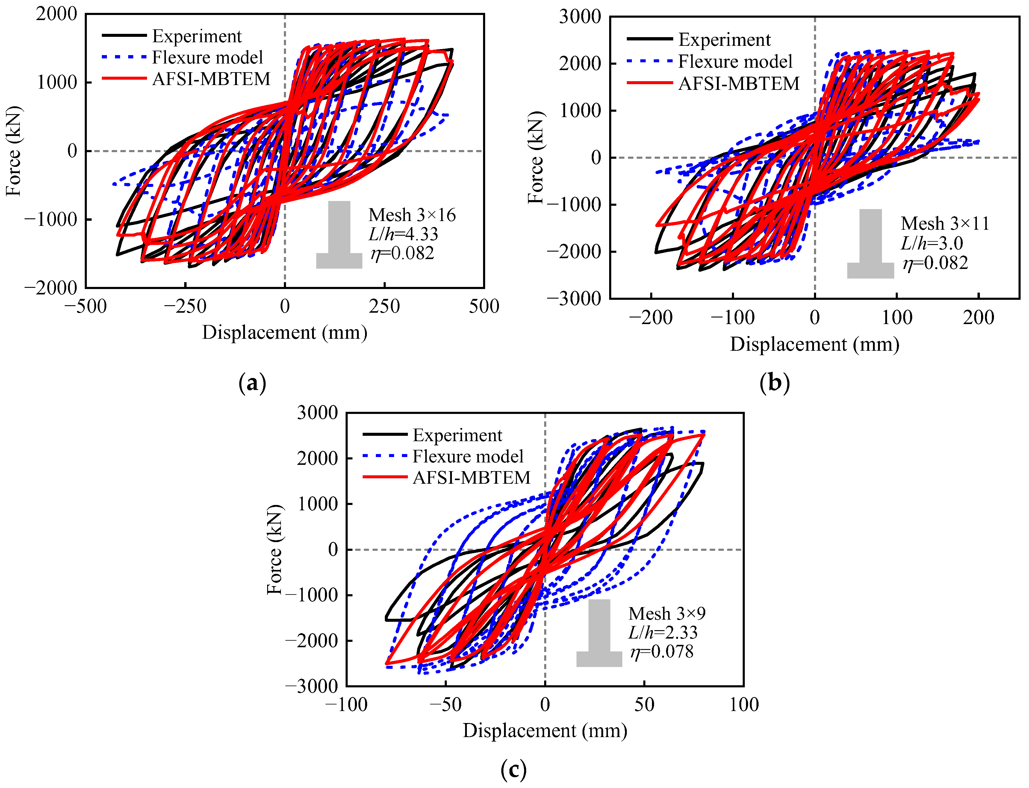
To reduce the influence of size effects, three full-scale rectangular hollow piers tested by Yeh et al. [16] were selected to validate the AFSI-MBTEM. The dimensions and reinforcement details are illustrated in Figure 3, and basic information about these hollow piers is presented in Table 1. Among these, specimens PS1 and PI1 exhibit flexure-dominated failure (F); however, the latter develops diagonal cracks even though its aspect ratio is 3.0. Specimen PS2, with only 20% of the required stirrup ratio, exhibits shear-dominated failure (S). These hollow piers were modeled using the AFSI-MBTEM as illustrated in Figure 2, and a sensitivity analysis was performed to determine the optimal mesh size for the membrane elements, ensuring a balance between accuracy and computational efficiency.
Figure 4 presents the symmetric force–displacement hysteretic curves of rectangular hollow piers simulated using the AFSI-MBTEM, in comparison with the experimental data. Additionally, numerical simulation results obtained using the fiber-based beam–column elements (flexure model) are also presented for comparison. The results from the AFSI-MBTEM are in good agreement with the experimental data, accurately capturing the initial stiffness, yield plateau, and peak strength of all rectangular hollow piers. Furthermore, the AFSI-MBTEM can precisely capture most hysteretic characteristics of the rectangular hollow piers, including strength degradation, reloading/unloading stiffness degradation, pinching effect, plastic displacement, and energy dissipation capacity. However, the flexure model fails to capture the experimental unloading stiffness degradation at different displacement levels, and it also leads to exaggerated energy dissipation and sudden strength drops. Clearly, due to the neglect of shear effects, the flexure model cannot accurately predict the hysteretic curves—even for flexure-controlled hollow piers.

3. Parametric Analysis Under Cyclic Loading

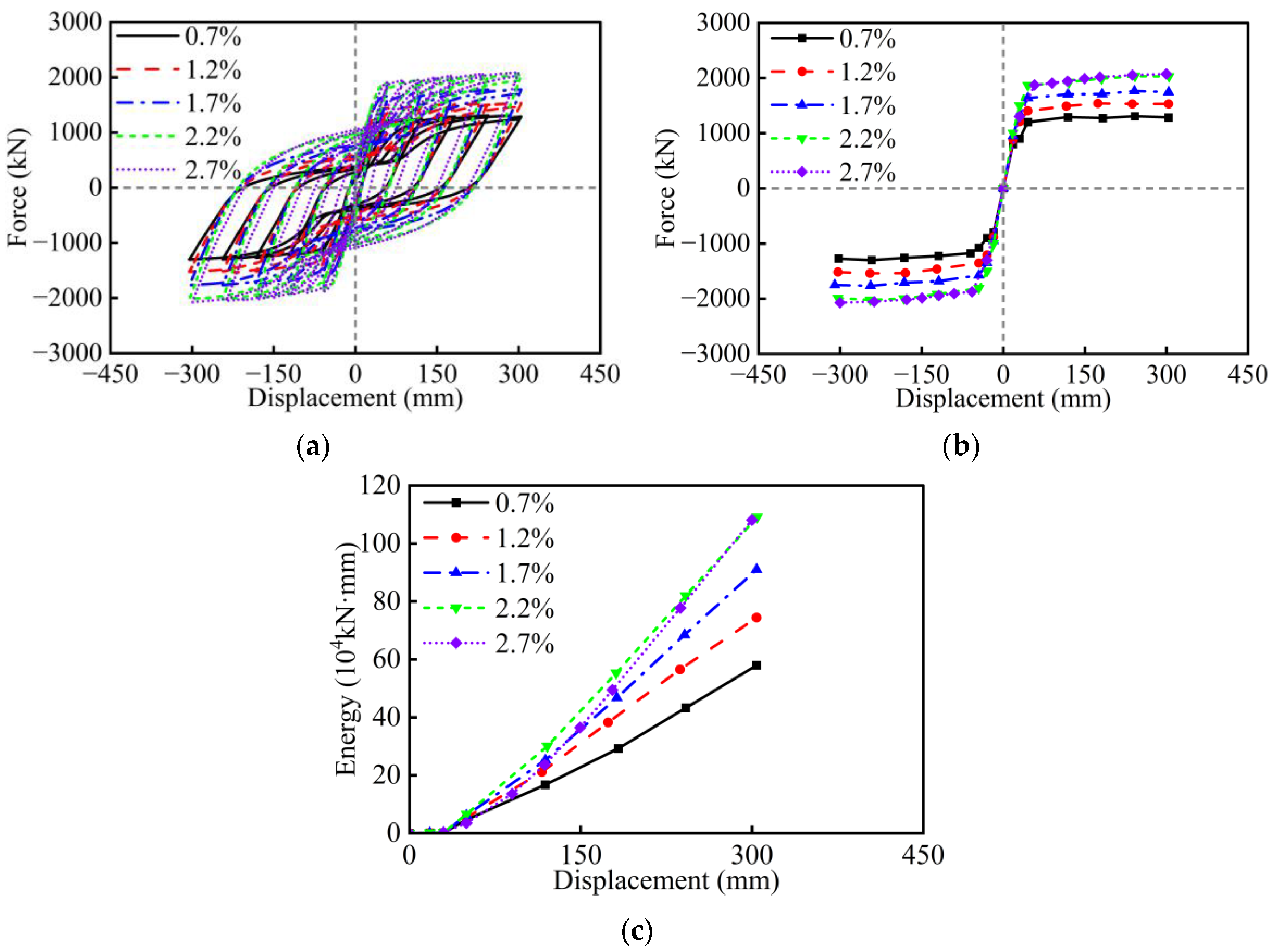
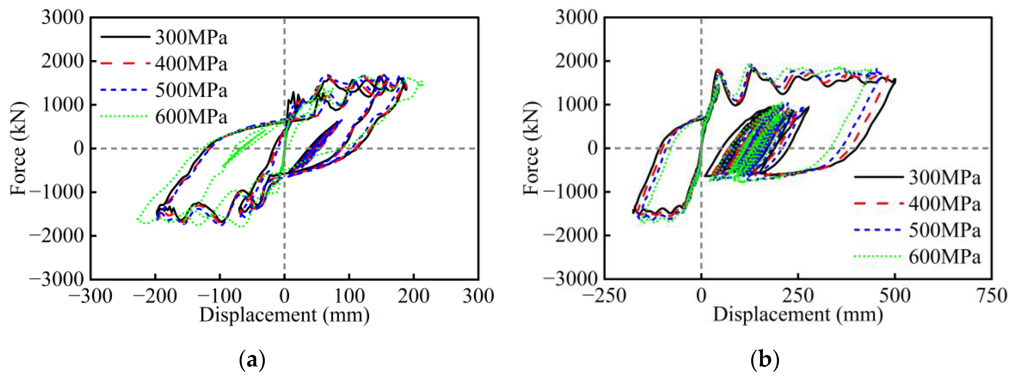
Using the full-scale hollow pier PS1 as the benchmark model, a parametric analysis was first conducted under cyclic loading using the validated AFSI-MBTEM. In this study, the selected design parameters include aspect ratio, width-to-depth ratio, wall thickness ratio, axial load ratio, longitudinal rebar ratio, stirrup ratio, concrete strength, and longitudinal rebar strength. Based on existing hollow piers constructed over the past decades and the latest design codes, the ranges of these design parameters are summarized in Table 2. Figure 5, Figure 6, Figure 7, Figure 8, Figure 9, Figure 10 and Figure 11 present the symmetric hysteretic curves, skeleton curves, and dissipated energy of RC hollow piers with different parameter values.
Figure 5 shows the influence of the aspect ratio on the seismic behavior of RC hollow piers. As the aspect ratio increases, the displacement capacity of the hollow pier significantly increases, while its maximum strength and lateral stiffness decrease. The failure mode transitions from shear-dominated to flexure-dominated, enabling the full development of the plastic hinge region. Consequently, both ductility and energy dissipation capacity are significantly improved. However, the increased plastic deformation may also lead to an increase in residual displacement. Therefore, a moderate increase in the aspect ratio (e.g., 4–6) is beneficial for improving the hysteretic behavior of hollow piers, as it avoids shear failure and ensures good deformation capacity, energy dissipation capacity, and post-earthquake recoverability.
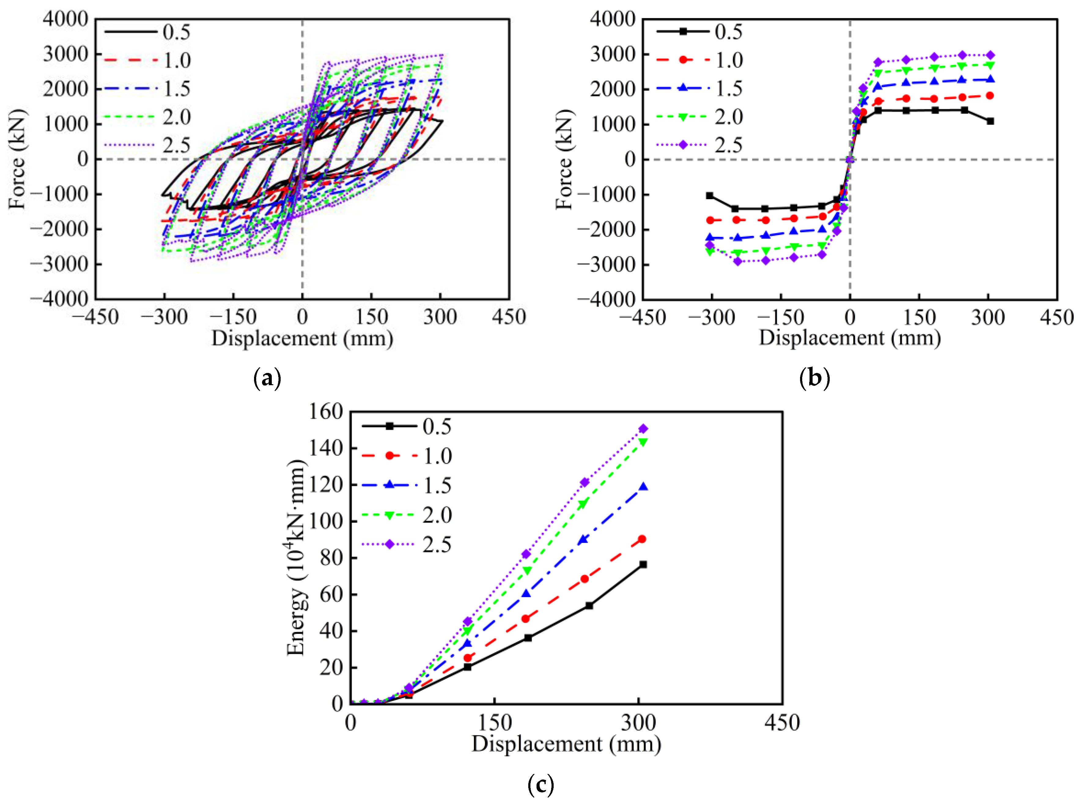
Figure 6 shows the influence of the width-to-depth ratio on the seismic behavior of RC hollow piers. Under displacement-controlled loading, a larger width of hollow section leads to higher sectional stiffness and greater moment demand to achieve the same deformation distribution. The flexural strength, energy dissipation capacity, and lateral stiffness of the hollow pier increase significantly with the increase in the width-to-depth ratio. When the width-to-depth ratio is reduced to 0.5, strength degradation is observed in force–displacement loops due to concrete crushing or fracture of longitudinal rebars. Meanwhile, a too large width-to-depth ratio may restrict the plastic deformation capacity, increase construction costs, and enhance the inertial forces induced from self-mass under earthquakes. Therefore, width-to-depth ratios of 1.0 to 2.0 are suggested for rectangular hollow piers.
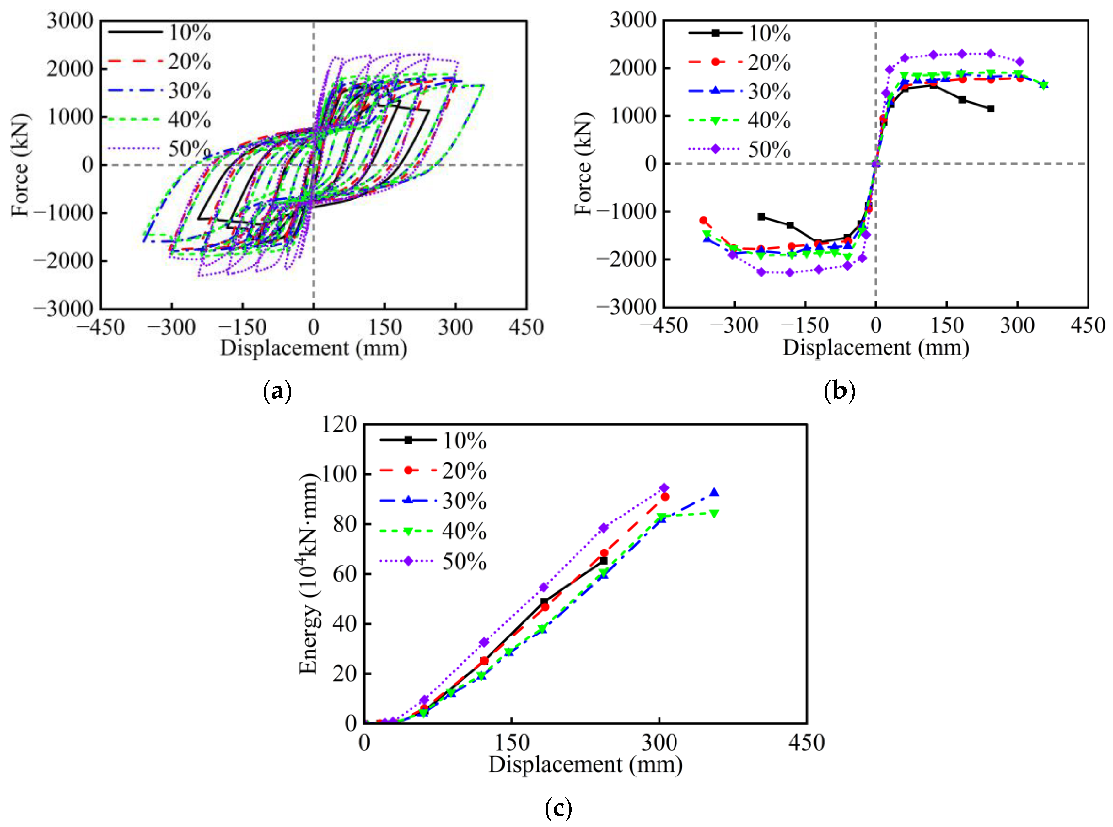
Figure 7 shows the influence of the wall thickness ratio on the seismic behavior of RC hollow piers. As the wall thickness ratio increases, the flexural stiffness and load-bearing capacity of the hollow pier are slightly improved. This enhancement is primarily attributed to the increase in effective moment of inertia and the overall compressive stability of the cross-section. When the wall thickness ratio reaches approximately 50%, the pier section approaches a solid section, resulting in a significant increase in load-bearing capacity. A thicker wall helps reduce the risk of local buckling, thereby moderately enhancing the shear and compressive resistance of the member. In contrast, hollow piers with relatively thin walls often lead to lower shear and compressive capacity as well as reduced hysteretic performance and ductility. It can be seen that significant drops in strength and displacement are observed in hysteretic loops of hollow piers when the wall thickness ratio is 10%. In this study, a wall thickness ratio range of 20% to 40% is suggested for hollow piers.
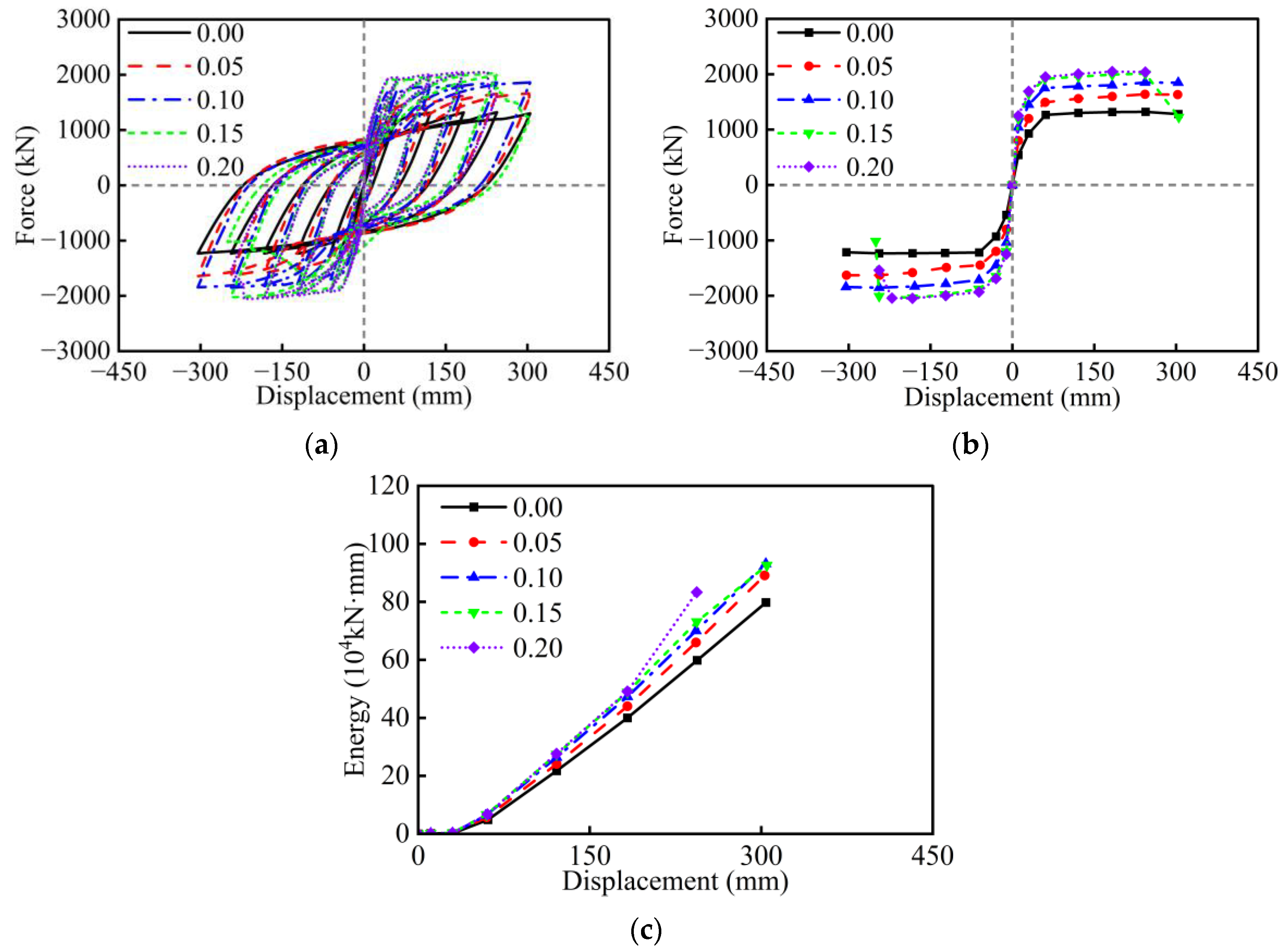
Figure 8 shows the influence of the axial load ratio on the seismic behavior of RC hollow piers. As the axial load ratio increases, the initial stiffness and ultimate bearing capacity of the hollow pier are enhanced. Bridge piers are usually considered highly eccentric compression members, and increasing axial force will enhance their bending resistance. Within a reasonable range, increasing the axial load ratio contributes to better seismic bearing capacity of the hollow pier. However, the axial load ratio also has a significant impact on ductility and energy dissipation. When the axial load ratio is large, the core concrete may fail prematurely, along with narrower hysteresis loops, indicating reduced energy dissipation efficiency. Under high axial load conditions, the failure mode is more likely to shift toward brittle crushing, weakening the seismic resilience of hollow piers. It can be seen that significant strength drops are observed in force–displacement loops of hollow piers due to concrete crushing when the axial load ratio reaches 0.15. When the axial load ratio is very low (0), the slight strength degradation is primarily caused by the fracture of the longitudinal reinforcement, as the lack of axial load eliminates confinement effects and accelerates the yielding and rupture of the bars. Therefore, axial load ratios of 0.05 to 0.10 are recommended for hollow piers.
Figure 9 shows the influence of the longitudinal rebar ratio on the seismic behavior of RC hollow piers. The increase in longitudinal rebar ratio significantly improves the flexural strength, lateral stiffness, and energy dissipation of the hollow pier, thereby contributing to the overall seismic performance. When the longitudinal rebar ratio becomes excessively high, the lateral stiffness of the hollow pier may become too large, leading to a reduction in ductility due to premature crushing of concrete. This is the exact reason that the hysteretic responses of the hollow pies with ratios of 2.2% and 2.7% are similar. Conversely, excessively low ratios can cause the premature yielding of longitudinal rebar, increasing the risk of brittle failure. Therefore, a moderate longitudinal rebar ratio (e.g., 1.2–2.2%) is suggested for a balance of flexural strength and plastic deformation.
Figure 10 shows the influence of the stirrup ratio on the seismic behavior of RC hollow piers. Within the parameter range considered in this study, increasing the stirrup ratio results in the hysteretic curves, maximum strength, and energy dissipation remaining largely unchanged. This is primarily because the baseline stirrup already provides sufficient confinement to suppress crack propagation and prevent concrete crushing. In fact, full-scale hollow pier experiments by Yeh et al. [16] revealed that the stirrup ratio of 0.44% exhibits good seismic ductility. Excessive stirrup ratios may also lead to reinforcement congestion, construction difficulties, and reduced cost-effectiveness. Taking comprehensive consideration into account, the stirrup ratios of 0.6% to 1.2% are suggested for hollow piers.
Figure 11 shows the influence of concrete strength on the seismic behavior of RC hollow piers. As the concrete strength increases, the hysteretic curves, lateral strength, and energy dissipation of the hollow pier almost remain unchanged, which maintains consistency with the stirrup ratio (Figure 8). This indicates that the concrete strength has little impact on the flexural loading capacity of the hollow pier, which is mainly contributed to by the longitudinal rebars. According to engineering practice, C40 is widely used for hollow piers.
Figure 12 shows the influence of longitudinal rebar strength on the seismic behavior of RC hollow piers. As the strength of longitudinal rebar increases, the flexural strength of the hollow pier slightly improves. This is primarily because high-strength steel reinforcement can provide greater tensile force before yielding, thereby enhancing the overall flexural resistance of the section. During the yielding stage, high-strength reinforcement can delay the onset of plastic deformation, allowing the hollow pier to maintain a higher strength reserve within the elastic range. Moreover, high-strength longitudinal rebar will slightly reduce residual deformation and energy dissipation capacity due to weakened plastic deformation. According to engineering practice, 400 MPa is commonly used for RC hollow piers.

4. Parametric Analysis Under Earthquakes

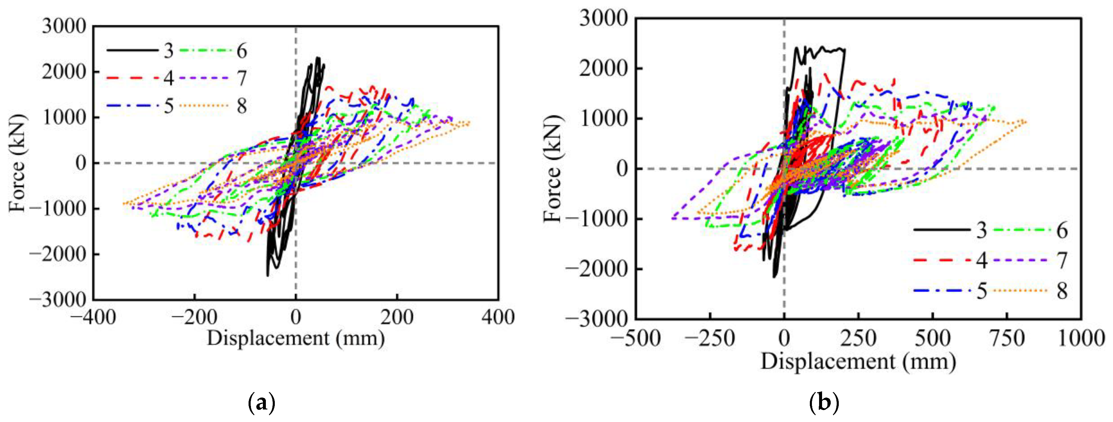
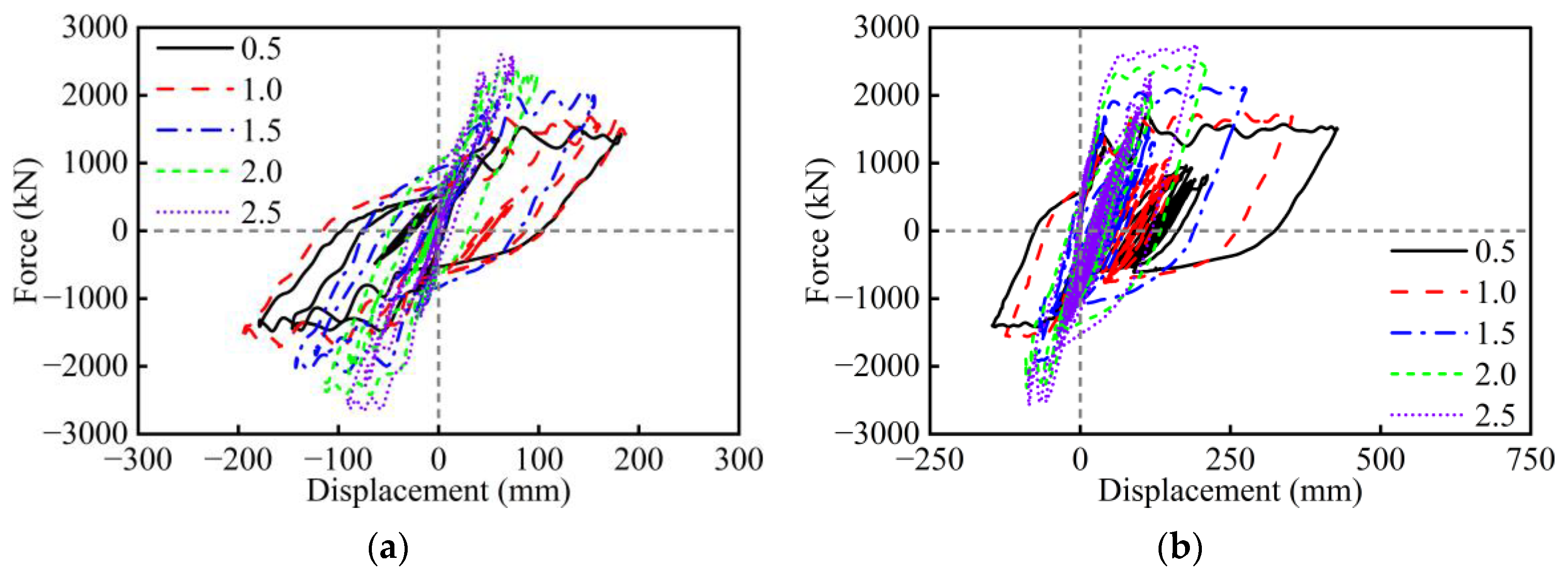
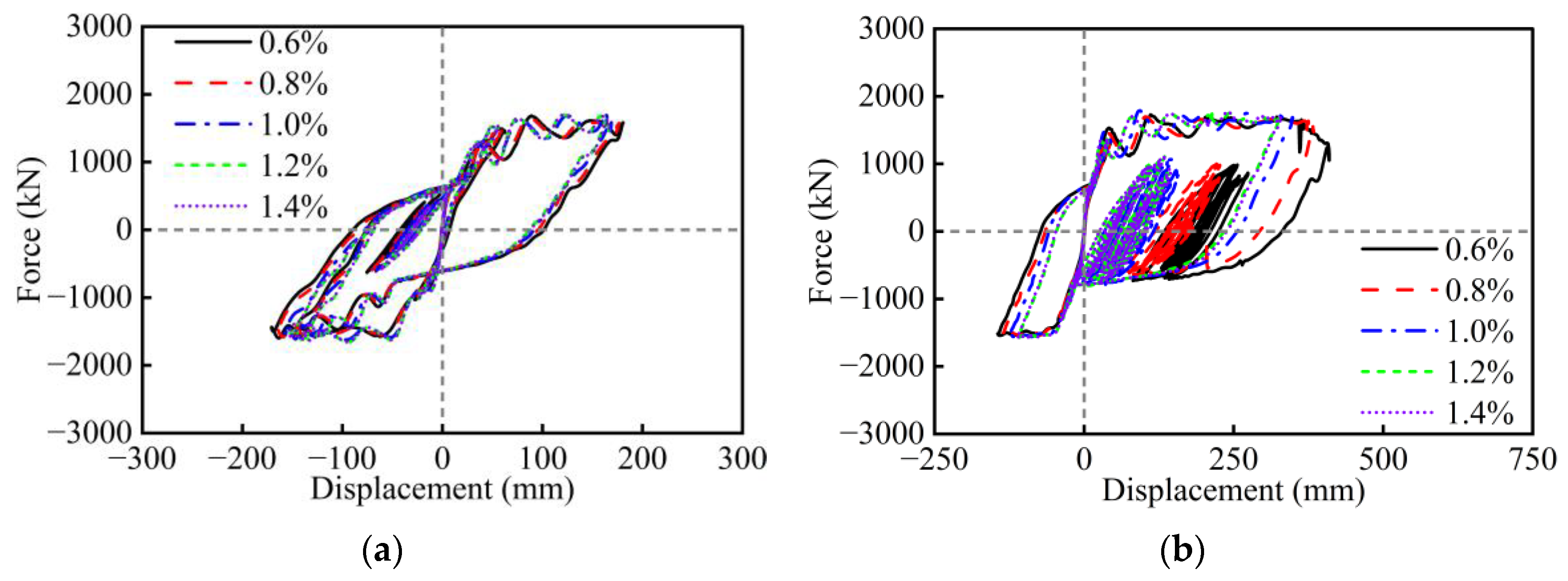
Given that rectangular hollow piers in mountainous regions are often located near active faults, near-fault ground motions were used for nonlinear time history analysis. According to the common types of sites in mountainous areas of Southwest China, two near-fault earthquake records were selected. The acceleration time histories and response spectra of these ground motions are shown in Figure 13. Figure 14, Figure 15, Figure 16, Figure 17, Figure 18, Figure 19, Figure 20 and Figure 21 present the asymmetric hysteresis curves of RC hollow piers with different design parameters.
As shown in Figure 14, the displacement capacity of the hollow piers increases with the aspect ratio. Specifically, when the aspect ratio is small, the hollow piers are more prone to shear failure, exhibit greater stiffness, and produce steeper hysteresis loops with limited energy dissipation. As the aspect ratio increases, pier stiffness gradually decreases, and the failure mode transitions from shear-dominated to flexure-dominated. The hysteresis loops become fuller, indicating significant improvements in ductility and energy dissipation capacity. In particular, under the earthquake RSN722, piers with larger aspect ratios exhibit superior ductility, enabling more extensive plastic deformation but also resulting in larger residual displacement. Therefore, the proper control of the aspect ratio is crucial for enhancing seismic performance, especially under near-fault, high-intensity earthquake conditions.
As shown in Figure 15, with the increase in the width-to-depth ratio of hollow piers, both the flexural strength and lateral stiffness are significantly enhanced. The hysteresis curves progressively exhibit higher strength but reduced deformation capacity, indicating that the improvement in load-bearing capacity is accompanied by a loss of ductility. Compared with RSN1119, this effect becomes more pronounced under the earthquake RSN722.
As shown in Figure 16, increasing the wall thickness ratio improves the flexural stiffness and overall stability of the hollow pier. Piers with higher wall thickness ratios exhibit smaller displacement responses and greater load-bearing capacity. A higher wall thickness ratio increases the section’s moment of inertia and compressive area, thereby enhancing stiffness and improving the member’s resistance to deformation. Simulation results indicate that at higher wall thickness ratios, the hysteresis loops are fuller, and energy dissipation capacity is enhanced. In particular, under the earthquake RSN722, piers with thicker walls maintain stable hysteretic performance, demonstrating superior plastic deformation capacity. However, when the wall thickness is excessively large, the advantages of the hollow section may diminish, and the seismic behavior approaches that of a solid section. In contrast, at lower wall thickness ratios, the hollow pier exhibits poor hysteretic performance with too large displacement and residual displacement responses.
As shown in Figure 17, with the increase in axial load ratio, the initial stiffness and flexural strength of the hollow pier are significantly enhanced, and the peak displacement of the hysteresis curve decreases, particularly under the earthquake RSN722. This improvement is due to the increased axial load, which enhances the concrete’s confinement, improving its compressive strength. As a result, the hollow pier exhibits higher stiffness and strength, especially in the elastic stage, allowing the pier to bear higher loads without premature yielding. However, as the axial load ratio increases, the vulnerability of the concrete crushing gradually increases, which may lead to a shift in the brittle failure mode. As seen in Figure 17b, significant strength drops are observed in dynamic hysteretic curves when the axial load ratio is 0.15 and 0.20. Furthermore, an excessively small axial load ratio will increase the displacement and residual deformation, with poor energy dissipation capacity. Therefore, in design, it is important to control the axial load ratio appropriately to avoid brittle failure caused by excessive axial load ratio and ensure that the pier maintains good plastic deformation capacity with smaller residual deformation.
As shown in Figure 18, with the increase in longitudinal rebar ratio, the flexural capacity and overall stiffness of the hollow pier are significantly enhanced. A higher reinforcement ratio helps improve the pier’s resistance to seismic loads and delays yielding, thereby enhancing the seismic performance under strong earthquakes. However, as the longitudinal rebar ratio continues to increase, the post-yield plastic deformation capacity of the hollow pier begins to decline. The hysteresis loops become progressively slimmer, and the energy dissipation capacity diminishes. This effect is especially evident under the earthquake RSN722, where hollow piers with higher reinforcement ratios exhibit a noticeable reduction in ductility and residual displacement. This is attributed to stress concentration in the longitudinal bars at high reinforcement levels, which restricts the development of the plastic hinge region. As a result, the pier’s energy dissipation mechanism shifts from ductile deformation to a stiffer, more brittle resistance mode.
As shown in Figure 19, increasing the stirrup ratio does not enhance the flexural strength, ductility, and energy dissipation of the hollow pier under the earthquake RSN1119, which is similar to the results under cyclic loading. However, under the earthquake RSN722, it can be seen that there is an obvious difference in hysteretic responses. The increase in the stirrup ratio greatly reduces the displacement and residual deformation, along with smaller dissipated energy. In view of dynamic responses, the suggested stirrup ratios of hollow piers range from 0.8% to 1.2%.
As shown in Figure 20, increasing the concrete strength does not obviously enhance the flexural strength, ductility, and energy dissipation of the hollow pier under the earthquake RSN1119, which is similar to the results under cyclic loading. However, under the earthquake RSN722, displacement responses increase with the reduction in concrete strength. Specifically, the hollow pier exhibits poor hysteretic performance with too large a displacement and sudden strength drops. At the same time, high-strength concrete is not necessary since it will increase costs and restrict the development of the plastic hinge region. Therefore, it can be concluded again that C40 is suitable for RC hollow piers.
As shown in Figure 21, high-strength reinforcement allows the hollow pier to resist greater tensile forces, thereby improving the flexural strength. However, an increase in reinforcement strength does not always translate to improved seismic performance. Under the earthquake RSN722, the hollow pier with high-strength steel tends to exhibit smaller displacement responses and residual deformation, though with slightly reduced energy dissipation. Overall, 400 MPa is suitable for RC hollow piers, and 500 Mpa is better in view of residual deformation.

5. Parametric Analysis Under Different PGAs

In the previous sections, the AFSI-MBTEM has been successfully applied to simulate the cyclic and dynamic responses of RC hollow piers. It should be noted that peak ground acceleration (PGA), a key parameter for assessing the intensity of seismic events, has a significant influence on seismic responses of RC hollow piers. Therefore, investigating the effect of PGA on the seismic performance of RC hollow piers is crucial. This section will focus on examining the displacement responses of RC hollow piers with different design parameters under various PGAs (0.2 g, 0.4 g, 0.6 g, 0.8 g, 1.0 g, and 1.2 g).
Figure 22 illustrates the influence of eight design parameters on the top displacement responses of RC hollow piers under varying PGAs. As the PGA increases, the top displacement consistently grows. Among these parameters, the aspect ratio, width-to-depth ratio, wall thickness ratio, and longitudinal rebar ratio have significant effects. As the aspect ratio increases, the pier becomes more flexible, leading to a substantial increase in top displacement. Conversely, the increase in width-to-depth ratio, wall thickness ratio, and longitudinal rebar ratio will enhance the flexural stiffness of hollow piers, resulting in a significant reduction in displacement. However, the longitudinal rebar ratio has almost no influence on displacement responses at a low PGA level of 0.2 g, as the longitudinal rebar is not activated before yielding. In contrast, the geometry parameters, including the aspect ratio, width-to-depth ratio, and wall thickness ratio, have a great influence on the low PGAs. As for the remaining parameters, the influences of PGA on displacement responses are relatively small. The varying trends of stirrup ratio and concrete strength are similar since the enhancement of stirrup amount will increase the confined concrete strength.

6. Conclusions

This study employs the AFSI-MBTEM to systematically analyze symmetric and asymmetric hysteretic responses of RC hollow piers under cyclic loading, earthquakes, and varying PGA conditions, examining the influence of design parameters. The main conclusions are summarized as follows.
  • The AFSI-MBTEM successfully reproduces the symmetric experimental hysteretic results of three full-scale RC rectangular hollow piers with flexure and shear failure modes. It predicts the initial stiffness, yield plateau, peak strength, and most hysteretic characteristics, including strength degradation, stiffness degradation, pinching effect, plastic displacement, and energy dissipation with excellent accuracy, convergence, and efficiency, demonstrating its capability for reliable nonlinear seismic analysis of hollow piers.
  • Under cyclic loading, the aspect ratio, width-to-depth ratio, wall thickness ratio, axial load ratio, and longitudinal rebar ratio have a significant influence on the seismic performance of RC hollow piers. However, the effects of stirrup ratio, concrete strength, and longitudinal rebar strength are relatively minor. Specifically, excessively small values of the width-to-depth ratio and wall thickness ratio, as well as an excessively large axial load ratio, will lead to sudden drops in the lateral strength of RC hollow piers. The amount of longitudinal rebar and stirrup, as well as the strength of materials, should take into account the seismic performance, cost, and construction.
  • Under earthquakes, the seismic responses of RC hollow piers exhibit a similar trend to those observed under cyclic loading, though asymmetric hysteretic responses are observed due to the asymmetric main velocity pulses of near-field earthquakes. However, the influence of stirrup ratio, concrete strength, and longitudinal rebar strength becomes clear under strong earthquakes, especially in terms of residual deformation.
  • Compared with other relevant studies, the influence trend of the design parameters on the seismic behavior of RC hollow piers under cyclic loading and earthquakes maintains consistency with experimental results. Moreover, reasonable ranges of the design parameters suggested in this study for RC hollow piers are as follows: aspect ratio of 4–6, width-to-depth ratio of 1.0–2.0, wall thickness ratio of 20–40%, axial load ratio of 0.05–0.10, longitudinal rebar ratio of 1.2–2.2%, stirrup ratio of 0.8–1.2%, concrete strength of C40, and longitudinal rebar strength of 400 MPa and 500 MPa.
  • Under different PGA conditions, the aspect ratio, width-to-depth ratio, wall thickness ratio, and longitudinal rebar ratio have a significant influence on the displacement responses of RC hollow piers. However, axial load ratio, stirrup ratio, concrete strength, and longitudinal rebar strength have minor effects under different PGAs.
Although the AFSI-MBTEM model has been validated against experimental results, further experimental verification under a wider range of loading scenarios would enhance the reliability of the conclusions. Moreover, the interactions between parameters deserve investigation in future work to enable more precise determination of the optimal values.

Author Contributions

Conceptualization, Q.Q.; Methodology, Z.P.; Software, H.C.; Validation, H.Y. and C.S.; Investigation, L.D., H.Y. and J.L.; Data curation, L.D. and H.C.; Writing—original draft, Z.P.; Writing—review & editing, Q.Q.; Supervision, C.S. All authors have read and agreed to the published version of the manuscript.

Funding

This research was funded by the National Key R&D Program of China [No. 2023YFB2604402], the National Natural Science Foundation of China [No. 51978581], and the Sichuan Science and Technology Program [No. 2025ZNSFSC1315].

Data Availability Statement

The original contributions presented in this study are included in the article. Further inquiries can be directed to the corresponding author.

Conflicts of Interest

The authors declare no conflict of interest.

References

  1. Parghi, A.; Alam, M.S. Seismic collapse assessment of non-seismically designed circular RC bridge piers retrofitted with FRP composites. Compos. Struct. 2017, 160, 901–916. [Google Scholar] [CrossRef]
  2. Qi, Q.; Shao, C.; Cui, H.; Huang, H.; Wei, W.; Wang, C.; Zhuang, W. Shaking table tests and numerical studies on the seismic behaviors of FPB in railway continuous beam bridges. Eng. Struct. 2023, 290, 116318. [Google Scholar] [CrossRef]
  3. Zhang, Y.-y.; Harries, K.A.; Yuan, W.-c. Experimental and numerical investigation of the seismic performance of hollow rectangular bridge piers constructed with and without steel fiber reinforced concrete. Eng. Struct. 2013, 48, 255–265. [Google Scholar] [CrossRef]
  4. Tong, T.; Yuan, S.; Zhuo, W.; He, Z.; Liu, Z. Seismic retrofitting of rectangular bridge piers using ultra-high performance fiber reinforced concrete jackets. Compos. Struct. 2019, 228, 111367. [Google Scholar] [CrossRef]
  5. Billah, A.M.; Alam, M.S.; Bhuiyan, M.R. Fragility analysis of retrofitted multicolumn bridge bent subjected to near-fault and far-field ground motion. J. Bridg. Eng. 2013, 18, 992–1004. [Google Scholar] [CrossRef]
  6. Qi, Q.; Shao, C.; Wei, W.; Xiao, Z.; He, J. Seismic performance of railway rounded rectangular hollow tall piers using the shaking table test. Eng. Struct. 2020, 220, 110968. [Google Scholar] [CrossRef]
  7. Sun, Z.; Wang, D.; Wang, T.; Wu, S.; Guo, X. Investigation on seismic behavior of bridge piers with thin-walled rectangular hollow section using quasi-static cyclic tests. Eng. Struct. 2019, 200, 109708. [Google Scholar] [CrossRef]
  8. Shao, C.; Qi, Q.; Wang, M.; Xiao, Z.; Wei, W.; Hu, C.; Xiao, L. Experimental study on the seismic performance of round-ended hollow piers. Eng. Struct. 2019, 195, 309–323. [Google Scholar] [CrossRef]
  9. Li, Z.-X.; Du, C.-y.; Liang, X.; Zhao, B. Flexural behavior of circular hollow RC piers with reduced amounts of inner hoops. Int. J. Concr. Struct. Mater. 2020, 14, 9. [Google Scholar] [CrossRef]
  10. Liang, X.; Du, C.; Zhao, B.; Li, Z. Seismic performance of circular hollow concrete columns. Struct. Concr. 2021, 22, 3140–3155. [Google Scholar] [CrossRef]
  11. Nie, L.; Jiang, L.; Zhou, W.; Wu, X.; Lai, Z.; Feng, Y. Seismic performance of railway rocking hollow tall piers under near-fault ground motions. Soil Dyn. Earthq. Eng. 2023, 166, 107774. [Google Scholar] [CrossRef]
  12. Xu, X.; Wen, X.; Han, Z.; Chen, G.; Li, C.; Zheng, W.; Zhnag, S.; Ren, Z.; Xu, C.; Tan, X. Lushan M S7. 0 earthquake: A blind reserve-fault event. Chi. Sci. Bull. 2013, 58, 3437–3443. [Google Scholar] [CrossRef]
  13. Parsons, T.; Ji, C.; Kirby, E. Stress changes from the 2008 Wenchuan earthquake and increased hazard in the Sichuan basin. Nature 2008, 454, 509–510. [Google Scholar] [CrossRef] [PubMed]
  14. Ni, S.; Wang, W.; Li, L. The April 14th, 2010 Yushu earthquake, a devastating earthquake with foreshocks. Sci. China Earth Sci. 2010, 53, 791. [Google Scholar] [CrossRef]
  15. Mander, J.; Priestley, M.; Park, R. Behaviour of ductile hollow reinforced concrete columns. Bull. N. Z. Soc. Earthq. Eng. 1983, 16, 273–290. [Google Scholar] [CrossRef]
  16. Yeh, Y.-K.; Mo, Y.; Yang, C. Full-scale tests on rectangular hollow bridge piers. Mater. Struct. 2002, 35, 117–125. [Google Scholar] [CrossRef]
  17. Yeh, Y.-K.; Mo, Y.; Yang, C. Seismic performance of rectangular hollow bridge columns. J. Struct. Eng. 2002, 128, 60–68. [Google Scholar] [CrossRef]
  18. Mo, Y.; Nien, I. Seismic performance of hollow high-strength concrete bridge columns. J. Bridg. Eng. 2002, 7, 338–349. [Google Scholar] [CrossRef]
  19. Pinto, A.; Molina, J.; Tsionis, G. Cyclic tests on large-scale models of existing bridge piers with rectangular hollow cross-section. Earthq. Eng. Struct. Dyn. 2003, 32, 1995–2012. [Google Scholar] [CrossRef]
  20. Calvi, G.M.; Pavese, A.; Rasulo, A.; Bolognini, D. Experimental and numerical studies on the seismic response of RC hollow bridge piers. Bull. Earthq. Eng. 2005, 3, 267–297. [Google Scholar] [CrossRef]
  21. Cassese, P.; Ricci, P.; Verderame, G.M. Experimental study on the seismic performance of existing reinforced concrete bridge piers with hollow rectangular section. Eng. Struct. 2017, 144, 88–106. [Google Scholar] [CrossRef]
  22. Han, Q.; Du, X.; Zhou, Y.; Lee, G.C. Experimental study of hollow rectangular bridge column performance under vertical and cyclically bilateral loads. Earthq. Eng. Eng. Vibr. 2013, 12, 433–445. [Google Scholar] [CrossRef]
  23. Zahn, F.; Park, R.; Priestley, M. Flexural strength and ductility of circular hollow reinforced concrete columns without confinement on inside face. Struct. J. 1990, 87, 156–166. [Google Scholar]
  24. Yeh, Y.-K.; Mo, Y.; Yang, C. Seismic performance of hollow circular bridge piers. Struct. J. 2001, 98, 862–871. [Google Scholar]
  25. Cassese, P.; De Risi, M.T.; Verderame, G.M. Seismic assessment of existing hollow circular reinforced concrete bridge piers. J. Earthq. Eng. 2020, 24, 1566–1601. [Google Scholar] [CrossRef]
  26. Zhou, J.; Li, J.; Shen, Y. Quasi-static testing of railway rounded rectangular hollow tall piers having semi-hinged column-base details. Eng. Struct. 2022, 250, 113403. [Google Scholar] [CrossRef]
  27. Chen, X.; Li, C. Seismic assessment of tall pier bridges with double-column bents retrofitted with buckling restrained braces subjected to near-fault motions. Eng. Struct. 2021, 226, 111390. [Google Scholar] [CrossRef]
  28. Lu, W.; Peng, W.-Q.; Zhu, L.; Gao, C.; Tang, Y.-D.; Zhou, Y.-W.; Su, W.; Zeng, B. Experimental and numerical study of static behavior of precast segmental hollow bridge piers. Materials 2022, 15, 6991. [Google Scholar] [CrossRef]
  29. Yang, D.; Wang, Z.; Zhang, Y.; Pan, W.; Wang, J.; Shi, J. Seismic performance of the PVA fiber reinforced concrete prefabricated hollow circular piers with socket and slot connection. Buildings 2022, 12, 1339. [Google Scholar] [CrossRef]
  30. Cassese, P.; De Risi, M.T.; Verderame, G.M. A modelling approach for existing shear-critical RC bridge piers with hollow rectangular cross section under lateral loads. Bull. Earthq. Eng. 2019, 17, 237–270. [Google Scholar] [CrossRef]
  31. Yu, J.; Li, J.; Guo, W.; Fan, C.; Zeng, C.; Chen, X. Seismic evaluation method on shear strength models for round-end hollow piers of high-speed railway bridges. Structures 2023, 50, 23–38. [Google Scholar] [CrossRef]
  32. Qi, Q.; Shao, C.; Yang, H.; Cui, H.; Chen, Z.; Gong, W. Axial-flexure-shear model for seismic analysis of RC thin-walled hollow piers. Soil Dyn. Earthq. Eng. 2025, 195, 109375. [Google Scholar] [CrossRef]
  33. Qi, Q.; Jiang, L.; Shao, C.; Yang, H.; Shao, J.; Zhou, Y.; Cui, H. Hysteretic behavior modeling of RC walls considering axial-flexure-shear interaction. J. Build. Eng. 2025, 111, 113628. [Google Scholar] [CrossRef]
  34. Mo, Y.; Zhong, J.; Hsu, T.T. Seismic simulation of RC wall-type structures. Eng. Struct. 2008, 30, 3167–3175. [Google Scholar] [CrossRef]
  35. Polimeru, V.K.; Laskar, A. CSMM based seismic fragility analysis of shear dominant RC hollow rectangular bridge piers. Bull. Earthq. Eng. 2021, 19, 5051–5085. [Google Scholar] [CrossRef]
  36. Feng, D.-C.; Wu, G.; Sun, Z.-Y.; Xu, J.-G. A flexure-shear Timoshenko fiber beam element based on softened damage-plasticity model. Eng. Struct. 2017, 140, 483–497. [Google Scholar] [CrossRef]
  37. Berto, L.; Saetta, A.; Scotta, R.; Talledo, D. A coupled damage model for RC structures: Proposal for a frost deterioration model and enhancement of mixed tension domain. Constr. Build. Mater. 2014, 65, 310–320. [Google Scholar] [CrossRef]
  38. Lu, X.; Xie, L.; Guan, H.; Huang, Y.; Lu, X. A shear wall element for nonlinear seismic analysis of super-tall buildings using OpenSees. Finite Elem. Anal. Des. 2015, 98, 14–25. [Google Scholar] [CrossRef]
  39. Kolozvari, K.; Orakcal, K.; Wallace, J.W. New opensees models for simulating nonlinear flexural and coupled shear-flexural behavior of RC walls and columns. Comput. Struct. 2018, 196, 246–262. [Google Scholar] [CrossRef]
  40. Lu, Y.; Panagiotou, M.; Koutromanos, I. Three-dimensional beam-truss model for reinforced concrete walls and slabs–part 1: Modeling approach, validation, and parametric study for individual reinforced concrete walls. Earthq. Eng. Struct. Dyn. 2016, 45, 1495–1513. [Google Scholar] [CrossRef]
  41. Ceresa, P.; Petrini, L.; Pinho, R.; Sousa, R. A fibre flexure–shear model for seismic analysis of RC-framed structures. Earthq. Eng. Struct. Dyn. 2009, 38, 565–586. [Google Scholar] [CrossRef]
Figure 1. The schematic diagram of the AFSI-MBTEM for rectangular hollow piers.
Symmetry 17 01553 g001
Figure 2. The numerical implementation of the AFSI-MBTEM for rectangular hollow piers.
Symmetry 17 01553 g002
Figure 3. Geometry and reinforcement details of hollow section (unit: mm).
Symmetry 17 01553 g003
Figure 4. Simulated and experimental hysteretic curves of RC hollow piers: (a) PSI, (b) PI1, (c) PI2.
Symmetry 17 01553 g004
Figure 5. Aspect ratio: (a) hysteresis curve; (b) skeleton curve; (c) dissipated energy.
Symmetry 17 01553 g005
Figure 6. Width-to-depth ratio: (a) hysteresis curve; (b) skeleton curve; (c) dissipated energy.
Symmetry 17 01553 g006
Figure 7. Wall thickness ratio: (a) hysteresis curve; (b) skeleton curve; (c) dissipated energy.
Symmetry 17 01553 g007
Figure 8. Axial load ratio: (a) hysteresis curve; (b) skeleton curve; (c) dissipated energy.
Symmetry 17 01553 g008
Figure 9. Longitudinal rebar ratio: (a) hysteresis curve; (b) skeleton curve; (c) dissipated energy.
Symmetry 17 01553 g009
Figure 10. Stirrup ratio: (a) hysteresis curve; (b) skeleton curve; (c) dissipated energy.
Symmetry 17 01553 g010
Figure 11. Concrete strength: (a) hysteresis curve; (b) skeleton curve; (c) dissipated energy.
Symmetry 17 01553 g011
Figure 12. Longitudinal rebar strength: (a) hysteresis curve; (b) skeleton curve; (c) dissipated energy.
Symmetry 17 01553 g012
Figure 13. Acceleration time histories (a) and response spectra (b) of the near-field earthquakes.
Symmetry 17 01553 g013
Figure 14. Hysteresis curves of hollow piers with different aspect ratios: (a) RSN1119; (b) RSN722.
Symmetry 17 01553 g014
Figure 15. Hysteresis curves of hollow piers with different width-to-depth ratios: (a) RSN1119; (b) RSN722.
Symmetry 17 01553 g015
Figure 16. Hysteresis curves of hollow piers with different wall thickness ratios: (a) RSN1119; (b) RSN722.
Symmetry 17 01553 g016
Figure 17. Hysteresis curves of hollow piers with different axial load ratios: (a) RSN1119; (b) RSN722.
Symmetry 17 01553 g017
Figure 18. Hysteresis curves of hollow piers with different longitudinal rebar ratios: (a) RSN1119; (b) RSN722.
Symmetry 17 01553 g018
Figure 19. Hysteresis curves of hollow piers with different stirrup ratios: (a) RSN1119; (b) RSN722.
Symmetry 17 01553 g019
Figure 20. Hysteresis curves of hollow piers with different concrete strength: (a) RSN1119; (b) RSN722.
Symmetry 17 01553 g020
Figure 21. Hysteresis curves of hollow piers with different longitudinal rebar strength: (a) RSN1119; (b) RSN722.
Symmetry 17 01553 g021
Figure 22. Pier top displacement: (a) aspect ratio; (b) width-to-depth ratio; (c) wall thickness ratio; (d) axial load ratio; (e) longitudinal rebar ratio; (f) stirrup ratio; (g) concrete strength; (h) longitudinal rebar strength.
Symmetry 17 01553 g022aSymmetry 17 01553 g022b
Table 1. Basic information on the selected rectangular hollow piers.
No.SpecimenFailure ModeHeightDepthL/hfcLongitudinal RebarStirrupη
L (mm)h (mm)(MPa)Layoutρ1 (%)fyl (MPa)s (mm)ρw (%)fyw (MPa)
1PS1F650015004.3334.064ϕ221.72460801.103430.082
2PI1F450015003.034.064ϕ221.724601200.435100.082
3PI2S350015002.2234.064ϕ221.724182000.264200.078
Table 2. Design parameters and values.
Design ParameterValueNote
Aspect ratio3, 4, 5, 6, 7, 8Geometry
Width-to-depth ratio0.5, 1.0, 1.5, 2.0, 2.5
Wall thickness ratio (%)10, 20, 30, 40, 50
Axial load ratio0, 0.05, 0.1, 0.15, 0.2Gravity
Longitudinal rebar ratio (%)0.7, 1.2, 1.7, 2.2, 2.7Reinforcement
Stirrup ratio (%)0.6, 0.8, 1.0, 1.2, 1.4
Concrete strength (MPa)C30, C40, C50, C60Strength
Longitudinal rebar strength (Mpa)300, 400, 500, 600
Disclaimer/Publisher’s Note: The statements, opinions and data contained in all publications are solely those of the individual author(s) and contributor(s) and not of MDPI and/or the editor(s). MDPI and/or the editor(s) disclaim responsibility for any injury to people or property resulting from any ideas, methods, instructions or products referred to in the content.