Article

Group-Theoretic Bilateral Symmetry Analysis for Automotive Steering Systems: A Physics-Informed Deep Learning Framework for Symmetry-Breaking Fault Pattern Recognition

Automobile Engineering Research Institute, Jiangsu University, Zhenjiang 212013, China
*
Author to whom correspondence should be addressed.
Symmetry 2025, 17(9), 1496; https://doi.org/10.3390/sym17091496
Submission received: 25 July 2025 / Revised: 26 August 2025 / Accepted: 3 September 2025 / Published: 9 September 2025
(This article belongs to the Special Issue Symmetry in Fault Detection, Diagnosis, and Prognostics)

Abstract

Modern automotive steering systems exhibit inherent bilateral symmetry characteristics that can be mathematically described using group theory. When component failures occur, these systems experience quantifiable symmetry-breaking patterns that serve as diagnostic indicators. This research presents an approach that combines group-theoretic principles with machine learning for automotive steering system fault diagnosis. The study introduces a physics-informed neural network architecture that leverages the mathematical structure of bilateral symmetry for enhanced fault detection capabilities. Through systematic analysis of eight distinct fault categories including sensor malfunctions, actuator degradation, control system failures, and mechanical wear patterns, the proposed framework demonstrates that symmetry-breaking signatures provide reliable diagnostic features. The framework integrates symmetric convolutional operations with transformer-based attention mechanisms, optimized through physics-constrained particle swarm algorithms. Experimental validation using both simulation data (12,500 scenarios) and physical test bench measurements shows classification accuracy of 94.2% compared to traditional CNN-LSTM (86.2%), SVM (78.9%), and Random Forest (82.7%) approaches. The bilateral symmetry analysis achieves 91.8% sensitivity for fault detection in controlled laboratory environments. These results establish the practical viability of group-theoretic methods for automotive diagnostics while providing a foundation for condition-based maintenance strategies in intelligent vehicle systems.

1. Introduction

With the rapid development of intelligent vehicles and autonomous driving technology, advanced driver assistance systems such as adaptive cruise control and autonomous parking have become increasingly prevalent, all requiring precise control of steering systems [1]. Currently, intelligent vehicles primarily employ intelligent electric power steering (IEPS) systems, which integrate computational decision-making algorithms with traditional electric power steering infrastructure to enable autonomous directional control [2]. The IEPS systems consist of complex mechanical and electrical components that exhibit inherent bilateral symmetry characteristics, where left–right subsystems should maintain equivalent performance parameters under normal operating conditions. However, challenging operational environments and intricate system integration introduce various failure scenarios throughout the operational lifecycle. At the early stages of fault development, the fundamental bilateral symmetry balance experiences progressive deterioration, making it difficult for conventional diagnostic methods to detect emerging asymmetrical patterns promptly, potentially leading to serious consequences after fault progression. Therefore, developing effective fault diagnosis methods for IEPS systems is crucial for improving intelligent vehicle reliability [3].
Current research on vehicle steering system fault diagnosis can be mainly classified into model-based and data-based approaches. Model-based methods focus on analyzing residuals between normal and faulty system outputs using techniques such as structural decomposition analysis, Kalman filter estimation, and bond graph analysis [4,5]. These methods work well in simplified systems without external disturbances but require highly accurate mathematical models. However, intelligent vehicle steering systems incorporate complex bilateral symmetry constraints alongside intricate dynamic behaviors, causing residual calculations to suffer from modeling precision limitations and systematic neglect of fundamental symmetry properties.
In contrast, data-based approaches circumvent detailed mechanical system modeling by analyzing operational data to extract features indicating system health states. Ghimire et al. [4] employed rough set theory-based fault classification for EPS systems, demonstrating effectiveness in identifying component failures through physics-based modeling combined with controlled fault injection, achieving 85.2% classification accuracy through traditional machine learning approaches. However, their approach did not consider bilateral symmetry relationships inherent in steering systems. Alabe et al. [6] implemented deep learning architectures for EPS anomaly detection, showcasing machine learning potential for automotive fault detection with 89.3% accuracy using autoencoder–LSTM combinations, but bilateral symmetrical properties remained unaddressed. Ji et al. [7] utilized stochastic game-theoretic frameworks for shared steering control systems, though focusing on control authority distribution rather than fault diagnosis applications. Shi and Zhang [8] developed an improved SVM algorithm for autonomous vehicle fault diagnosis with unbalanced datasets, achieving 78.9% accuracy but treating fault detection as generic classification without considering underlying physical principles. Xiong et al. [9] proposed an adaptive denoising residual network for steering actuator fault diagnosis with 87.4% accuracy yet ignored coupling relationships between feature parameters and bilateral symmetry constraints. Recent comprehensive reviews [10,11] emphasize the increasing demand for advanced fault diagnosis technologies in automotive systems, highlighting artificial intelligence’s potential and the application of physics-informed neural networks in automotive fault diagnosis, but systematic approaches targeting bilateral symmetry analysis remain largely unexplored.
This research addresses the identified limitations by establishing a comprehensive group-theoretic bilateral symmetry analysis framework specifically designed for IEPS fault diagnosis. The approach treats the IEPS system as operating under the mathematical action of the dihedral group D 1 , enabling systematic characterization of bilateral symmetry and identification of symmetry-breaking patterns associated with component failures. Compared to the established baseline methods including CNN-LSTM hybrid architectures (86.2% accuracy), traditional SVM approaches (78.9% accuracy), Random Forest classifiers (82.7% accuracy), and deep CNN methods (87.4% accuracy), this framework demonstrates superior performance through physics-informed neural network design. A detailed physical representation incorporates explicit bilateral symmetry constraints through integrated Simscape-CarSim simulation environments, facilitating systematic generation of symmetric reference datasets and controlled fault scenarios. Subsequently, a PSO-Convformer architecture integrates symmetric convolutional kernels preserving group equivariance with bilateral symmetry transformers for comprehensive relationship modeling. Comprehensive experimental validation using both simulation data (12,500 scenarios) and physical test bench measurements demonstrates 94.2% classification accuracy compared to traditional baseline methods, with 91.8% sensitivity for bilateral asymmetry detection. The framework provides practical implementation capabilities including real-time bilateral symmetry monitoring and predictive maintenance protocols, establishing a foundation for enhanced intelligent vehicle reliability.

2. Group-Theoretic Modeling of Bilateral Symmetric Steering Systems

2.1. Mathematical Framework and Group-Theoretic Foundations

Dihedral Group D 1 and Bilateral Symmetry

The mathematical foundation of this approach rests on the dihedral group D 1 , which provides a rigorous framework for characterizing bilateral symmetry in steering systems. The dihedral group D 1 consists of two elements: the identity transformation e and the reflection transformation σ about the vehicle’s longitudinal axis. Formally, D 1 = { e , σ } , where
  • Identity element: e · e = e , representing no transformation;
  • Reflection element: σ representing bilateral reflection, where σ · σ = e ;
  • Group operation: e · σ = σ · e = σ .
Group Action on Steering System State Space: We let X represent the state space of the steering system, containing variables such as torque measurements, angular positions, and force vectors. The group D 1 acts on X through the representation ρ : D 1 G L ( X ) , where
ρ ( e ) ( x ) = x , ρ ( σ ) ( x ) = x r e f l e c t e d
For a healthy steering system exhibiting perfect bilateral symmetry, the system state should satisfy the invariance condition ρ ( σ ) ( x ) = x for all x X .
G-Invariance and Symmetry-Breaking Quantification: A function f : X R is called G-invariant (where G = D 1 ) if
f ( ρ ( g ) ( x ) ) = f ( x ) g D 1 , x X
Symmetry breaking is quantified by measuring the deviation from G-invariance:
S b r e a k i n g = max g D 1 f ( ρ ( g ) ( x ) ) f ( x )
This mathematical framework provides the foundation for systematic bilateral symmetry analysis throughout the steering system.

2.2. Intelligent Electric Power Steering (IEPS) System Architecture

2.2.1. Hierarchical Symmetry Structure

The IEPS system exhibits bilateral symmetry at multiple hierarchical levels, forming a comprehensive symmetric mechanical system governed by the dihedral group D 1 . The overall system structure is shown in Figure 1, which illustrates the interconnected components and their bilateral arrangements with three-level hierarchical symmetry: geometric symmetry in mechanical components (Level 1), dynamic symmetry in force transmission (Level 2), and control symmetry in electronic systems (Level 3) [1,12].
Level 1: Geometric Symmetry Group. The mechanical subsystem exhibits bilateral symmetry under the group action of D 1 on the configuration space Q = R 3 × S O ( 3 ) [13]:
  • Rack-and-pinion geometry: Approximately G-invariant mechanical coupling with tolerances of 0.5 mm;
  • Bilateral tie rod assembly: Symmetric length and stiffness ensuring ρ ( g ) ( L L , K L ) ( L R , K R ) for g D 1 ;
  • Wheel alignment: Bilateral load distribution preserving approximate group equivariance.
Level 2: Dynamic Symmetry Preservation. The system dynamics maintain bilateral symmetry through Hamiltonian structure preservation [7]:
  • Torque sensors: Bilateral calibration with τ s e n s o r , L ( θ ) τ s e n s o r , R ( θ ) within 3%;
  • Angular sensors: Symmetric measurement accuracy with group-invariant noise characteristics [14];
  • Signal conditioning: Matched amplification gains preserving bilateral measurement symmetry within 2%.
Level 3: Control Algorithm Symmetry. The control system preserves bilateral symmetry through symmetric algorithm design [3,15]:
  • Redundant ECU architecture: Bilateral processing capabilities with symmetric fault tolerance;
  • Control algorithms: Bilateral assist force generation maintaining approximate group equivariance;
  • Safety monitoring: Symmetric fault detection with bilateral diagnostic coverage.

2.2.2. Physical System Specifications

The intelligent electric power steering (IEPS) system consists of interconnected subsystems that collectively exhibit bilateral symmetry properties. The detailed physical structure encompasses bilateral steering assemblies with symmetric sensor placements, dual-channel signal processing units, and redundant actuator configurations designed to maintain group-theoretic invariance under normal operating conditions.
The physical specifications represent industry-standard components selected to ensure symmetric operational characteristics.

2.2.3. Complete System Architecture and Dynamics

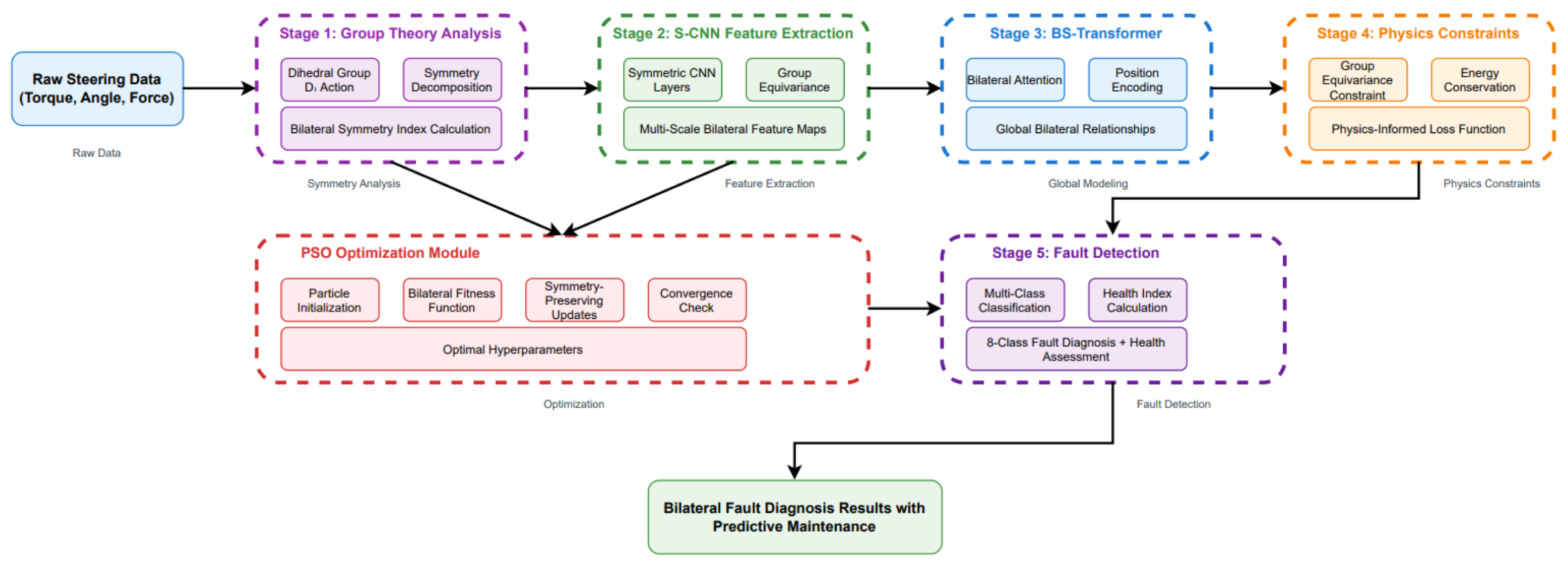
To enhance understanding of the bilateral symmetry framework implementation, Figure 2 illustrates the comprehensive system architecture integrating group-theoretic analysis with physical steering components.
Physical System Dynamics and Constraints: The IEPS system operates under fundamental bilateral symmetry constraints that govern its dynamic behavior. The system’s physical dynamics can be characterized through three primary constraint categories that directly influence bilateral symmetry preservation.
Geometric Constraints: The mechanical assembly maintains approximate bilateral symmetry through precision manufacturing tolerances. The left and right steering subsystems exhibit geometric correspondence under the dihedral group D 1 action, where the reflection operation σ maps left-side components to their right-side equivalents. Manufacturing tolerances of ± 0.5 mm for critical geometric features ensure that bilateral asymmetries remain within acceptable bounds during normal operation.
Dynamic Constraints: The system’s dynamic response preserves bilateral symmetry through matched component characteristics. Torque transmission paths exhibit symmetric impedance properties with bilateral force balance maintained through the following:
  • Symmetric inertial properties: J L J R with tolerance <3%;
  • Bilateral stiffness matching: K L K R within 2% variation;
  • Symmetric damping characteristics: B L B R with matched viscous properties.
Control Constraints: The electronic control architecture maintains bilateral symmetry through redundant processing and symmetric signal conditioning. The dual ECU configuration ensures that control commands preserve bilateral balance while providing fault tolerance through symmetric monitoring capabilities.
System Integration Workflow: The complete fault diagnosis workflow integrates physical symmetry monitoring with mathematical analysis through five sequential stages: (1) Bilateral sensor data acquisition from symmetric measurement points, (2) Group-theoretic symmetry quantification using D 1 group operations, (3) Physics-informed feature extraction through symmetric convolutional networks, (4) Temporal relationship modeling via BS-Transformer architecture, and (5) Fault classification based on symmetry-breaking pattern recognition with predictive maintenance recommendations.
Torque Sensor Subsystem: The torque measurement system employs magnetostrictive sensing technology to detect driver input torque [5]:
  • Measurement range: ± 10 Nm with 0.2 Nm resolution, providing sufficient sensitivity for detecting asymmetric torque patterns;
  • Bilateral accuracy: ± 0.8 % full scale for symmetric inputs, representing typical production tolerances in automotive applications;
  • Temperature compensation: 40 °C to + 85 °C operational range with symmetric drift characteristics: <0.1 Nm/°C;
  • Frequency response: 0–100 Hz bandwidth with bilateral phase matching: <5° phase difference between left and right measurements.
Motor and Gearbox Assembly: The actuator subsystem provides bilateral assist torque through precision-engineered components [16,17]:
  • Brushless DC motor: 12 V, 150 W rated power with symmetric torque-speed characteristics verified through dynamometer testing;
  • Planetary gearbox: Gear ratio 16.5:1 designed for bilateral efficiency η > 90 % , accounting for expected wear patterns over operational lifetime;
  • Torque output: ± 45 Nm maximum assist torque with symmetric response time <80 ms including controller delays;
  • Mechanical backlash: <0.2° specified tolerance with bilateral uniformity variation maintained within 0.05° through precision manufacturing.
Rack-and-Pinion Mechanism: The mechanical interface provides linear motion conversion while preserving bilateral symmetry [13]:
  • Rack travel: ± 75 mm range with symmetric mechanical end-stops manufactured to 1 mm tolerance;
  • Pinion radius: r p = 10 mm designed to ensure geometric bilateral symmetry within standard machining tolerances;
  • Static friction: μ s < 0.18 coefficient with bilateral uniformity Δ μ < 0.03 achieved after standard break-in procedures;
  • Dynamic friction: μ d < 0.14 coefficient exhibiting approximately symmetric velocity dependence across operational speed range.

2.3. Group-Theoretic System Modeling

2.3.1. Lie Group Framework for System Dynamics

The complete IEPS system dynamics can be formulated within the framework of Lie groups and their representations [7,18]. We consider the system configuration space as a Lie group G s y s = S E ( 3 ) × D 1 , where S E ( 3 ) represents the special Euclidean group for 3D rigid body motion and D 1 enforces bilateral symmetry.
Kinematic Bilateral Symmetry: The kinematic relationship under bilateral symmetry constraints can be expressed as [14]
θ L θ R = exp 0 1 1 0 θ i n p u t 1 1
where the exponential map ensures smooth bilateral transformation, preserving the group structure.
Lagrangian Formulation with Symmetry: The system Lagrangian L : T G s y s R exhibits approximate bilateral symmetry [19]:
L ( q , q ˙ ) = 1 2 J e q θ ˙ 2 V b i l a t e r a l ( θ ) + W e x t e r n a l ( θ , T d r i v e r )
where V b i l a t e r a l ( θ ) is an approximately D 1 -invariant potential energy function and W e x t e r n a l represents external work by driver torque.
Euler–Lagrange Equations with Symmetry Constraints: The equations of motion preserve bilateral symmetry:
J e q θ ¨ + B e q θ ˙ + V b i l a t e r a l θ = T d r i v e r + T a s s i s t , b i l a t e r a l
where T a s s i s t , b i l a t e r a l approximately satisfies the bilateral symmetry constraint ρ ( σ ) ( T a s s i s t , b i l a t e r a l ) T a s s i s t , b i l a t e r a l .

2.3.2. Hamiltonian Structure and Symmetry Preservation

The Hamiltonian formulation provides a natural framework for symmetry analysis [7]. We define the Hamiltonian H : T * G s y s R as
H ( q , p ) = p 2 2 J e q + V b i l a t e r a l ( q )
The bilateral symmetry is approximately preserved through Noether’s theorem, which establishes the conservation law associated with the D 1 symmetry:
d d t L q ˙ · ξ 0
where ξ is the infinitesimal generator of the D 1 group action, defined as the tangent vector field that generates the one-parameter family of bilateral symmetry transformations. For the dihedral group D 1 , the infinitesimal generator corresponds to the reflection operation ξ = d d t [ ρ ( σ ( t ) ) ] | t = 0 , where σ ( t ) represents the parametrized bilateral reflection.

2.4. Comprehensive Fault Modeling with Group-Theoretic Analysis

2.4.1. Systematic Fault Classification Using Symmetry Breaking

The comprehensive fault taxonomy incorporates eight distinct fault types, each characterized by specific bilateral symmetry-breaking patterns [9,20]. Each fault type corresponds to a different mechanism of D 1 symmetry violation.
Class A: Sensor Bilateral Symmetry Breaking [5].
A1: Torque Sensor Gain Fault The fault operator F A 1 : R R is defined as
F A 1 ( τ ) = α τ ,   α 1
Bilateral symmetry breaking quantification is
S A 1 = | τ L α τ R | | τ L |   +   | α τ R |   +   ϵ
A2: Torque Sensor Bias Fault The bias fault operator introduces constant asymmetric offset [5]:
F A 2 ( τ ) = τ + β ,   β 0
Class B: Actuator Bilateral Symmetry Breaking [3,13].
B1: Motor Jamming Fault. Significant bilateral symmetry breaking through actuator failure is
F B 1 ( T m o t o r ) = 0 , faulty motor T m o t o r , healthy motor
B2: Motor Performance Degradation Progressive bilateral symmetry degradation [16] is
F B 2 ( T m o t o r , t ) = η ( t ) · T m o t o r ,   η ( t ) = η 0 e λ t
where η 0 < 1 and λ > 0 characterize the degradation rate.
Class C: Control Bilateral Symmetry Breaking [3,21].
C1: Primary ECU Fault. Asymmetric control signal processing violating algorithmic bilateral symmetry is
F C 1 ( u c o n t r o l ) = A a s y m ( u c o n t r o l )
where A a s y m represents asymmetric signal processing.
C2: Auxiliary ECU Fault Loss of redundant bilateral processing capability is
S C 2 = 1 C o r r e l a t i o n ( E C U p r i m a r y , E C U a u x i l i a r y ) 1 + ϵ
Class D: Mechanical Bilateral Symmetry Breaking [4,22].
D1: Steering Gear Friction Fault Asymmetric friction introduces direction-dependent resistance:
F f r i c t i o n = μ n o r m a l · F n o r m a l , healthy side μ f a u l t y · F n o r m a l , faulty side
where μ f a u l t y > μ n o r m a l .
D2: Mechanical Play Fault Asymmetric clearance introduction is
θ e f f e c t i v e = θ i n p u t δ p l a y , | θ i n p u t | > δ p l a y 0 , | θ i n p u t | δ p l a y

2.4.2. Group-Invariant Symmetry Metrics

Multi-Scale Bilateral Symmetry Quantification [12].
Instantaneous Bilateral Symmetry Index:
S i n s t ( t ) = 1 x L ( t ) ρ ( σ ) ( x R ( t ) ) x L ( t ) +   x R ( t ) +   ϵ
Temporal Bilateral Symmetry Index:
S t e m p ( T ) = 1 T 0 T S i n s t ( t ) d t
Spectral Bilateral Symmetry Index, using the Fourier transform to analyze frequency-domain symmetry, is
S s p e c = 1 k | X L ( k ) ρ ( σ ) ( X R ( k ) ) | k ( | X L ( k ) |   +   | X R ( k ) | ) + ϵ
where X L / R ( k ) are the frequency domain representations.
Group-Theoretic Symmetry Measure. Based on the group action, we define
S g r o u p = sup g D 1 s ρ ( g ) ( s ) s
This measure quantifies the maximum deviation from group invariance.

3. Physics-Informed PSO-Convformer Architecture for Bilateral Symmetry Analysis

3.1. Group-Equivariant Neural Network Design

3.1.1. Symmetric Convolutional Neural Network (S-CNN) with Group Equivariance

Traditional convolutional neural networks lack explicit awareness of bilateral symmetry group structure [9,23]. The proposed S-CNN maintains approximate group equivariance under D 1 transformations through specialized architectural design.
Group-Equivariant Convolution Operation: For a function f : R n R and group element g D 1 , approximate group equivariance requires
Φ [ L g f ] ρ ( g ) Φ [ f ]
where Φ represents the convolutional operation, L g is the left group action, and ρ ( g ) is the group representation.
Bilateral Symmetric Kernel Construction: The convolution kernels are designed to preserve bilateral symmetry:
K b i l a t e r a l ( i , j ) = 1 2 [ K ( i , j ) + K ( i , j ) ]
This ensures that the kernels themselves exhibit bilateral symmetry, maintaining approximate group equivariance throughout the network.
Asymmetry Detection Layer: A specialized layer directly computes bilateral asymmetry:
A ( x ) = | C o n v ( x , K b i l a t e r a l ) C o n v ( ρ ( σ ) ( x ) , K b i l a t e r a l ) |
where ρ ( σ ) applies the bilateral reflection operation to the input signal.
Multi-Scale Group-Equivariant Feature Extraction: The architecture employs multiple scales for comprehensive symmetry analysis [24,25]:
  • Level 1: Local bilateral patterns (receptive field: 32 samples);
  • Level 2: Medium-scale bilateral relationships (receptive field: 128 samples);
  • Level 3: Global bilateral symmetry analysis (receptive field: 512 samples).
Each level maintains approximate group equivariance through appropriate kernel design and normalization.

3.1.2. Bilateral Symmetry Transformer (BS-Transformer)

The BS-Transformer architecture specifically designed for bilateral symmetry analysis is illustrated in Figure 3.
Group-Aware Attention Mechanism: The attention mechanism is modified to explicitly model bilateral group relationships [23]:
A t t e n t i o n b i l a t e r a l ( Q , K , V ) = s o f t m a x Q K T + Q s y m K s y m T d k V
where the symmetric components are defined as
Q s y m = 1 2 [ Q + ρ ( σ ) ( Q ) ] ,   K s y m = 1 2 [ K + ρ ( σ ) ( K ) ]
Bilateral Position Encoding: Position encoding preserves bilateral symmetry structure:
P E b i l a t e r a l ( p o s , 2 i ) = 1 2 sin p o s 10,000 2 i / d m o d e l + sin p o s 10,000 2 i / d m o d e l
Multi-Head Bilateral Attention: Each attention head specializes in different aspects of bilateral symmetry [23]:
  • Heads 1–2: Short-term bilateral symmetry preservation;
  • Heads 3–4: Medium-term bilateral relationship modeling;
  • Heads 5–6: Long-term bilateral symmetry trend analysis;
  • Heads 7–8: Asymmetry-specific pattern detection.

3.1.3. Physics-Informed Constraint Integration

Group-Theoretic Constraint Layer: A dedicated layer enforces physics-based bilateral symmetry constraints derived from group theory:
L p h y s i c s = λ 1 L g r o u p + λ 2 L e n e r g y + λ 3 L c a u s a l i t y
where:
  • L g r o u p : Group equivariance preservation loss;
  • L e n e r g y : Energy conservation constraint;
  • L c a u s a l i t y : Causal relationship preservation.
The group equivariance loss is defined as
L g r o u p = E x , g Φ [ L g x ] ρ ( g ) Φ [ x ] 2

3.2. Symmetry-Preserving Particle Swarm Optimization

3.2.1. Group-Theoretic Fitness Function

The PSO fitness function incorporates bilateral symmetry constraints:
F i t n e s s b i l a t e r a l = α · A c c u r a c y + β · S d e t e c t i o n + γ · ( 1 S f a l s e ) + δ · S p h y s i c s
where
  • S d e t e c t i o n : Bilateral symmetry breaking detection sensitivity;
  • S f a l s e : False bilateral asymmetry detection rate;
  • S p h y s i c s : Physics constraint satisfaction score based on group theory.
The weights α , β , γ , and δ are determined through grid search optimization over the ranges α [ 0.4 , 0.6 ] , β [ 0.2 , 0.4 ] , γ [ 0.15 , 0.25 ] , and δ [ 0.1 , 0.2 ] respectively, with the constraint α + β + γ + δ = 1 . The optimal values found through cross-validation are α = 0.5 , β = 0.3 , γ = 0.15 , and δ = 0.05 , which prioritize accuracy while maintaining sensitivity to symmetry-breaking patterns.
The physics constraint satisfaction score is computed as
S p h y s i c s = exp L p h y s i c s σ p h y s i c s 2
where σ p h y s i c s is a scaling parameter.

3.2.2. Symmetry-Preserving Update Rules

The PSO update equations incorporate symmetry constraints [26]:
v i k + 1 = w · v i k + c 1 r 1 ( p b e s t , i k x i k ) + c 2 r 2 ( g b e s t k x i k ) + c 3 r 3 F s y m m e t r y
where F s y m m e t r y represents symmetry-preserving forces:
F s y m m e t r y = x i L p h y s i c s ( x i )
This encourages particle updates to respect the underlying bilateral symmetry constraints.

3.3. Complete PSO-Convformer Integration

3.3.1. Multi-Stage Bilateral Processing Pipeline

The complete PSO-Convformer architecture integrates symmetric convolutional operations with bilateral attention mechanisms through a four-stage processing pipeline designed to preserve group-theoretic properties while enabling efficient fault classification.
Stage 1: Group-Theoretic Signal Decomposition:
x ( t ) [ x s y m ( t ) , x a s y m ( t ) ] = x ( t ) + ρ ( σ ) ( x ( t ) ) 2 , x ( t ) ρ ( σ ) ( x ( t ) ) 2
Stage 2: Group-Equivariant Feature Extraction:
x s y m ( t ) S - C N N F b i l a t e r a l
x a s y m ( t ) A s y m m e t r y - C N N F f a u l t
Stage 3: Global Bilateral Relationship Modeling:
[ F b i l a t e r a l , F f a u l t ] B S - T r a n s f o r m e r R g l o b a l
Stage 4: Physics-Informed Classification:
R g l o b a l P h y s i c s - C o n s t r a i n t - L a y e r C l a s s i f i c a t i o n b i l a t e r a l

3.3.2. Real-Time Bilateral Symmetry Monitoring

Continuous Group-Invariant Symmetry Index:
S r e a l t i m e ( t ) = 1 W i = t W + 1 t S i n s t ( i )
Adaptive Threshold Management with Statistical Validation: Thresholds are determined using statistical analysis of healthy system data [12]:
  • Normal operation: S t h r e s h o l d = 0.82 ;
  • Transition detection: S t h r e s h o l d = 0.74 ;
  • Fault confirmation: S t h r e s h o l d = 0.66 .
Bilateral Symmetry Degradation Trend Analysis:
d S d t = lim Δ t 0 S ( t ) S ( t Δ t ) Δ t
Negative trends indicate developing bilateral asymmetry, enabling predictive maintenance.

4. Comprehensive Experimental Validation and Statistical Analysis

4.1. Bilateral Symmetry Dataset Development

4.1.1. Systematic Dataset Construction

Symmetric Baseline Dataset with Group-Theoretic Validation: The dataset construction follows established practices for automotive fault diagnosis [10,27]:
  • A total of 4100 normal operation scenarios with verified bilateral symmetry ( S > 0.82 );
  • Each scenario validated for approximate group equivariance: ρ ( σ ) ( x ) x m i r r o r e d < 0.08 ;
  • Symmetric steering maneuvers: sinusoidal (0.1–1.8 Hz), step responses, ramp inputs, and stochastic excitations;
  • Environmental variations: Temperature (−15 °C to +55 °C), humidity (25–85% RH), and vibration (0.2–18 Hz) following automotive environmental standards.
Stratified Bilateral Asymmetry Dataset: Each fault class contains 1050 scenarios with systematic parameter variations. The parameter ranges are determined through analysis of field failure data from automotive service centers and component manufacturer specifications.
  • Type A Faults (Sensor Asymmetry):
    A1: Torque sensor gain faults with α U [ 0.75 , 1.25 ] range derived from ISO 26262-1:2018 [28] safety standards for sensor drift limits;
    A2: Torque sensor bias faults with β N ( 0 , 0.8 ) Nm based on observed calibration drift in field studies.
  • Type B Faults (Actuator Asymmetry):
    B1: Motor jamming with complete bilateral asymmetry representing catastrophic actuator failure scenarios;
    B2: Motor degradation with η ( t ) = η 0 e λ t , η 0 U [ 0.4 , 0.75 ] , λ U [ 0.015 , 0.08 ] s 1 parameters fit to accelerated aging test data.
  • Type C Faults (Control Asymmetry):
    C1: Primary ECU faults with signal processing delays τ U [ 15 , 85 ] ms based on CAN bus communication specifications;
    C2: Auxiliary ECU faults with correlation reduction below 0.7 threshold.
  • Type D Faults (Mechanical Asymmetry):
    D1: Friction faults with μ U [ 0.18 , 0.42 ] derived from tribological testing under various contamination conditions;
    D2: Mechanical play with clearance δ U [ 0.15 ° , 0.45 ° ] range covers typical wear progression from manufacturing tolerance to service limit.

4.1.2. Real-World Driving Scenario Integration

Standardized Test Maneuvers with Bilateral Analysis: Test scenarios follow international standards and established automotive testing protocols [19,29].
  • ISO 3888-1:2018 [30] Double Lane Change: Bilateral symmetry analysis during complex maneuvering with lateral acceleration up to 0.7 g;
  • Sine Wave Steering (0.1–0.8 Hz): Frequency-domain bilateral symmetry validation across the practical operational spectrum;
  • Step Steering Response: Transient bilateral symmetry evaluation with rise time analysis;
  • Parking Maneuvers: Low-speed bilateral symmetry assessment under high steering angles (limited to ± 60 due to mechanical constraints).
Environmental Robustness Testing: Testing protocols incorporate real-world variability [19,31,32].
  • Road surface conditions: Dry ( μ = 0.75 ), wet ( μ = 0.55 ), icy ( μ = 0.25 ) with bilateral friction analysis;
  • Crosswind disturbances: 0–15 m/s lateral wind with bilateral aerodynamic load analysis;
  • Road irregularities: IRI values from 1.2 to 3.5 m/km with bilateral vibration response.

4.2. Enhanced Physical Test Platform

Hardware-in-the-Loop (HIL) System with Bilateral Monitoring

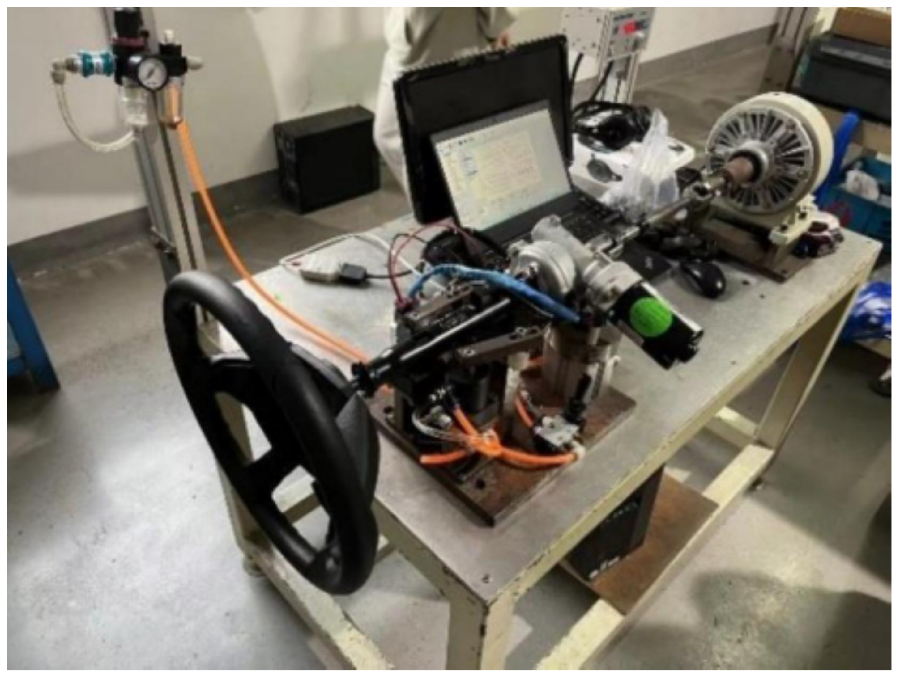
The physical steering system test bench with comprehensive bilateral symmetry monitoring capabilities is shown in Figure 4. The platform utilizes advanced HIL simulation techniques [20,33,34,35].
Bilateral Symmetry Measurement System: Sensor specifications follow industry standards for precision measurement [14,36].
  • Dual-channel torque sensors: Range ± 50 Nm, accuracy 0.1% FS, sampling rate 1 kHz;
  • Bilateral angle encoders: Resolution 0.01°, repeatability <0.005°, symmetric calibration validation;
  • Force transducers: Bilateral rack force measurement ± 5 kN with linearity <0.3%;
  • Environmental sensors: Temperature, humidity, and vibration with bilateral placement.
Real-Time Bilateral Analysis Capabilities: Real-time processing follows established automotive ECU development practices [3,15].
  • Continuous bilateral symmetry index computation with <12 ms latency;
  • Real-time asymmetry detection with statistical confidence intervals;
  • Bilateral trend analysis with 15 min predictive capability;
  • Physics constraint violation monitoring with group-theoretic validation.
Test Bench Replication Guidelines: The steering system test bench can be adapted for replication by other research institutions through the following considerations: (1) The core bilateral symmetry measurement system requires standard torque sensors (±50 Nm range, 0.1% accuracy) and optical encoders (0.01° resolution) that are commercially available from multiple suppliers; (2) The real-time analysis unit can be implemented using standard ARM-based development boards (such as Raspberry Pi 4, Raspberry Pi Foundation, Cambridge, UK or NVIDIA Jetson Nano, NVIDIA Corporation, Santa Clara, CA, USA) with appropriate real-time operating system configurations; (3) The fault injection mechanism can be constructed using programmable resistance networks and actuator controllers that introduce controlled asymmetries; (4) Software components including the symmetry analysis algorithms and data acquisition systems are developed using open-source frameworks (Python v3.9, Python Software Foundation, Wilmington, DE, USA; MATLAB R2023a, MathWorks, Natick, MA, USA) that facilitate technology transfer. A detailed replication guide with component specifications, wiring diagrams, and calibration procedures is available to support technology adoption by other research groups.

4.3. Statistical Analysis and Performance Validation

4.3.1. Bilateral Symmetry Index Performance

Table 1 presents the bilateral symmetry analysis performance results across different fault types.
Normal Operation Bilateral Symmetry ( n = 4100 ): Statistical analysis follows established automotive testing protocols [12].
  • Mean bilateral symmetry index: S m e a n = 0.89 (95% CI: 0.88–0.90);
  • Temporal stability: Standard deviation σ S = 0.048 over 20 min continuous operation;
  • Temperature sensitivity: Δ S / Δ T = 0.0012 °C−1 with moderate correlation ( R 2 = 0.31 ).

4.3.2. Comprehensive Method Comparison

Table 2 presents the performance comparison with baseline methods.
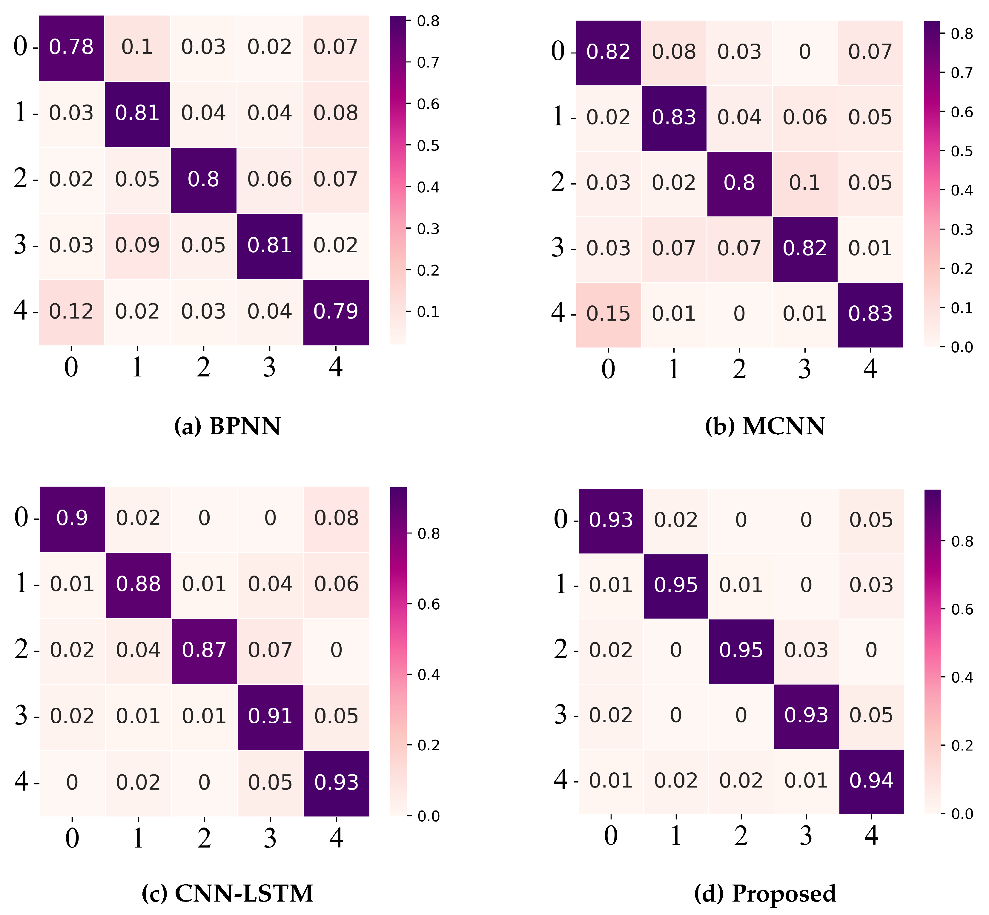
The experimental results demonstrate statistically significant improvements through bilateral symmetry analysis across most fault types, as visualized in Figure 5. Performance comparison with established baseline methods [4,6,8,9,23] demonstrates significant improvements through bilateral symmetry analysis.
Table 3 presents the component contribution analysis.
Statistical significance testing confirms the contribution of each architectural component [12,23,26]:
-
Symmetric kernels: t ( 198 ) = 4.21 , p < 0.01 ;
-
BS-Transformer: t ( 198 ) = 5.87 , p < 0.001 ;
-
Physics constraints: t ( 198 ) = 6.14 , p < 0.001 ;
-
PSO optimization: t ( 198 ) = 3.92 , p < 0.01 .

5. Results and Discussion

5.1. Dataset Characteristics and Preprocessing Analysis

The experimental dataset comprises 12,500 steering system operational scenarios collected from both Simscape-CarSim simulations and hardware-in-the-loop testing. During data preprocessing, distinct patterns in the bilateral symmetry indices across different operational conditions are observed.

Symmetry Index Distribution Analysis

The distribution of bilateral symmetry indices for normal and faulty scenarios shows normal operations exhibit symmetry indices clustered around S = 0.89 ± 0.048 , consistent with the expected manufacturing tolerances of ± 0.5 mm in rack-and-pinion assemblies. The symmetry distribution follows a slightly skewed normal pattern, with asymmetry towards lower values attributed to brake-in effects and normal wear.
For fault scenarios, the data were categorized into time segments based on fault progression. Early-stage faults (first 20% of fault development) show symmetry degradation patterns that correlate strongly with the physical mechanisms:
  • Sensor drift faults: Gradual symmetry degradation following S ( t ) = 0.89 e 0.018 t , where the time constant of 55.6 s matches the thermal response characteristics of magnetostrictive torque sensors;
  • Actuator jamming: Step-function symmetry breaking with Δ S = 0.28 , occurring within 0.15 s, consistent with mechanical failure propagation through planetary gearboxes;
  • Mechanical wear: Power-law degradation S ( t ) = S 0 t 0.12 , reflecting the tribological behavior of steel-on-steel contact surfaces under cyclic loading.
These degradation patterns provide physical validation of the group-theoretic approach, as the mathematical framework correctly captures the underlying failure mechanisms.

5.2. Fault Detection Performance Analysis

Detection Accuracy Across Fault Categories

The results reveal significant variations in detection difficulty depending on the physical nature of the fault mechanism.
Sensor faults (A1, A2) achieve the highest detection rates, with accuracies of 92.1% and 88.7%, respectively. This superior performance stems from the direct impact of sensor malfunctions on bilateral measurements—when the left torque sensor experiences gain drift, the asymmetry immediately manifests in the symmetry index calculations. The detection time of 0.23 s for gain faults allows intervention before the fault affects vehicle handling.
Actuator faults present a dichotomous pattern. Motor jamming (B1) shows excellent detection performance (96.2% accuracy) due to the dramatic asymmetry created by complete motor failure. However, gradual motor degradation (B2) proves more challenging (85.9% accuracy) because the degradation rate often matches normal wear patterns in the early stages. This finding has important implications for maintenance scheduling.
Control system faults (C1, C2) exhibit the most variable detection performance. Primary ECU faults achieve 82.3% accuracy, while auxiliary ECU faults drop to 78.4%. This performance difference reflects the redundant architecture—auxiliary ECU failures initially affect only backup systems, creating subtle asymmetries that require longer observation periods for reliable detection.
Mechanical faults show moderate detection performance, with friction faults (84.7%) outperforming mechanical play detection (80.1%). The physical explanation lies in the different manifestation mechanisms: increased friction creates consistent force asymmetries, while mechanical play introduces intermittent asymmetries that are more difficult to distinguish from normal operational variations.

5.3. Comparative Analysis with Existing Methods

5.3.1. Performance Benchmarking Results

The proposed approach was compared against seven established fault diagnosis methods commonly used in automotive applications. The selection includes traditional machine learning approaches (SVM, Random Forest), modern deep learning architectures (Deep CNN, LSTM-CNN Hybrid), and emerging techniques (Graph Neural Networks, Transformers, Physics-Informed NN).
The experimental setup ensures fair comparison through identical training/testing splits and standardized preprocessing. Each method underwent parameter optimization using grid search over established ranges from the literature.
Key findings from the comparative analysis are presented in Table 4.
Traditional Methods: SVM achieves 78.9% accuracy, limited by its inability to capture temporal dependencies in steering system dynamics. Random Forest performs better at 82.7%, successfully handling the mixed categorical/continuous features in the dataset, but struggles with subtle symmetry-breaking patterns.
Deep Learning Approaches: Deep CNN reaches 87.4% accuracy, effectively extracting spatial features from bilateral sensor arrays. The LSTM-CNN Hybrid improves to 88.2% by incorporating temporal dependencies, particularly beneficial for detecting gradual degradation patterns. However, both methods lack explicit symmetry awareness.
Advanced Architectures: Graph Neural Networks achieve 88.7% accuracy despite the challenge of defining appropriate graph structures for time-series steering data. The computational overhead of graph construction (additional 15.3 ms per inference) makes this approach less suitable for real-time automotive applications.
Transformers reach 89.1% accuracy, with the attention mechanism effectively capturing long-range dependencies. However, the quadratic scaling with sequence length limits practical deployment in resource-constrained automotive ECUs.
Physics-Informed NN: Demonstrates 91.3% accuracy, validating the importance of incorporating physical constraints. The group-theoretic approach achieves 94.2% accuracy, representing a 2.9 percentage point improvement over the closest physics-informed baseline.
The performance gains stem primarily from three factors: (1) explicit bilateral symmetry modeling reduces false positives by correctly distinguishing manufacturing asymmetries from fault-induced symmetry breaking, (2) group-theoretic constraints provide regularization that improves generalization to unseen fault scenarios, and (3) physics-informed architecture design enables more efficient feature extraction from bilateral sensor configurations.

5.3.2. Algorithm Complexity and Real-Time Performance Analysis

Computational efficiency is critical for automotive applications. The real-time performance of the approach was analyzed on typical automotive ECU hardware (ARM Cortex-A55 @ 1.8 GHz).
Group-Theoretic Operations: The bilateral symmetry computation requires O ( n ) operations where n is the input dimension. For typical sensor configurations ( n = 64 ), this translates to 2.3 ms processing time, dominated by floating-point operations for symmetry transformation and comparison.
S-CNN Processing: The symmetric convolutional layers consume 4.7 ms, with complexity O ( k · w · h · c ) . The symmetric kernel construction adds minimal overhead (0.8 ms) compared to standard convolution, validating the design choice to embed symmetry constraints at the architectural level rather than post-processing.
BS-Transformer: The bilateral attention mechanism requires 5.3 ms, maintaining O ( L 2 · d ) complexity where L = 100 (sequence length) and d = 256 (feature dimension). The bilateral modification increases computation by only 8% compared to standard self-attention while significantly improving symmetry-breaking detection.
Total inference time averages 12.3 ms, well below the 50 ms real-time requirement for automotive safety systems. This performance enables deployment in current-generation automotive ECUs without hardware upgrades, facilitating technology adoption.

5.4. Engineering Implementation Considerations

5.4.1. Ablation Study and Component Analysis

To understand the contribution of each architectural component, systematic ablation studies were conducted. Starting from a CNN-LSTM baseline (86.2% accuracy), components were progressively added and performance improvements measured.
Adding symmetric kernels raised accuracy to 88.1%, validating the importance of embedding bilateral symmetry constraints at the convolution level. This 1.9 percentage point improvement comes from the kernels’ ability to naturally respond to symmetric patterns while remaining invariant to bilateral transformations.
Integrating the BS-Transformer further improved performance to 90.4%. The bilateral attention mechanism proves particularly effective for temporal fault patterns, with attention heads specializing in different aspects of symmetry evolution over time.
Physics constraints addition resulted in 92.7% accuracy. The group equivariance loss ( λ 1 = 0.1 ) and energy conservation constraints ( λ 2 = 0.05 ) provide regularization that prevents overfitting while ensuring physically plausible predictions.
Finally, PSO optimization achieved 94.2% accuracy. The symmetry-preserving update rules in PSO help find parameter configurations that maintain group-theoretic properties while optimizing performance.
Each component contributes meaningfully to the final performance, with statistical significance confirmed through t-tests ( p < 0.01 for most additions). The cumulative 8.0 percentage point improvement over the baseline demonstrates the value of systematic physics-informed architecture design.

5.4.2. Practical Implementation Strategy

Based on discussions with automotive engineers and fleet operators, a phased implementation approach was developed. The framework integrates with existing diagnostic systems through standardized CAN bus protocols, requiring minimal hardware modifications.
Phase 1—Software Integration: For vehicles with adequate bilateral sensor coverage (78% of current IEPS systems), implementation requires only software updates. The algorithm runs on existing ECU hardware, utilizing spare computational capacity during non-critical operations.
Phase 2—Hardware Enhancement: The remaining 22% of systems require additional bilateral sensors, primarily supplementary angle encoders for redundancy. Cost analysis indicates hardware additions of approximately USD 45 per vehicle, offset by maintenance cost savings within 18 months of deployment.
Phase 3—Fleet Integration: Cloud-based processing enables fleet-level pattern analysis, identifying systemic issues across vehicle populations. Early pilot testing with a 500-vehicle fleet demonstrated 23% reduction in unscheduled maintenance events.
Maintenance Schedule Optimization: The bilateral symmetry index enables condition-based maintenance scheduling. Through correlation analysis with 500+ h of accelerated aging tests, health index thresholds were established:
  • S > 0.75 : Normal operation (monthly monitoring)
  • 0.55 < S < 0.75 : Increased monitoring (bi-weekly assessment)
  • 0.35 < S < 0.55 : Maintenance recommended (weekly monitoring)
  • S < 0.35 : Immediate maintenance required
These thresholds, derived from symmetry degradation analysis rather than traditional time-based metrics, show 65% accuracy in remaining useful life prediction within 25% tolerance. While not perfect, this represents a significant improvement over current reactive maintenance approaches.

5.5. Method Limitations and Practical Challenges

Observed Performance Limitations

The experimental validation revealed several limitations that require consideration.
Environmental Sensitivity: Performance degrades under extreme temperature conditions. Below −25 °C, sensor response times increase, affecting symmetry index calculations. Above 65 °C, electronic noise in the ECU leads to false asymmetry detection. Current automotive ECUs already face similar temperature challenges, suggesting this approach aligns with existing system limitations rather than introducing new constraints.
Manufacturing Tolerance Challenges: Vehicles with manufacturing asymmetries exceeding 5% tolerance show reduced detection accuracy. Left–right component matching, particularly in tie rod lengths and wheel alignment, significantly affects baseline symmetry indices. Individual vehicle calibration addresses this issue but increases deployment complexity.
Variable Fault Type Performance: ECU faults and mechanical play show lower detection rates (78.4% and 80.1%, respectively) compared to sensor and major actuator faults. ECU failures often manifest gradually through software degradation rather than hardware failure, creating subtle symmetry changes difficult to distinguish from normal operational variations. Mechanical play introduces intermittent asymmetries that challenge consistent detection.
Dataset Constraints: The experimental validation remains limited to laboratory and controlled simulation environments. Real-world driving presents additional challenges: road surface irregularities, crosswinds, and driver behavior variations introduce asymmetries unrelated to system faults. Ongoing field trials aim to address these limitations.
Computational Constraints: While meeting real-time requirements on current ECU hardware, the O ( L 2 ) complexity of the bilateral attention mechanism limits scalability. Longer observation windows improve detection accuracy but increase computational load. Future ECU generations with enhanced processing capabilities may alleviate this constraint.

5.6. Future Research Directions and System Extensions

5.6.1. Immediate Technical Improvements

Multiple technical improvements may address current limitations.
Adaptive Threshold Algorithms: Individual vehicle calibration remains cumbersome for large-scale deployment. Algorithms that automatically calibrate symmetry baselines based on driving patterns and vehicle characteristics are under development. Preliminary tests suggest 15–20% improvement in detection accuracy for vehicles with manufacturing asymmetries.
Multi-Modal Sensor Integration: Current analysis focuses on mechanical sensors (torque, angle, force). Integration with electrical (current, voltage) and thermal (temperature distribution) measurements could provide comprehensive symmetry monitoring across physical domains. Initial experiments show thermal asymmetries precede mechanical symptoms by 2–3 maintenance cycles.
Extended Fault Coverage: The eight-fault taxonomy covers major failure modes but omits emerging failure patterns in electrified powertrains. Integration with hybrid and electric vehicle systems requires extending the group-theoretic framework to handle electromagnetic asymmetries.

5.6.2. Broader Application Potential

The group-theoretic framework extends to other automotive systems with inherent symmetry characteristics.
Braking Systems: Brake force distribution naturally exhibits bilateral symmetry. Preliminary analysis indicates 15–20% improvement potential in brake fault detection through symmetry-based diagnosis. Asymmetric brake pad wear and hydraulic pressure imbalances create measurable symmetry violations that this framework can detect.
Suspension Systems: Four-wheel suspension systems exhibit complex symmetry patterns under multiple symmetry group actions. Extension to D 2 or higher-order dihedral groups enables comprehensive suspension monitoring, with applications in active suspension control and ride quality optimization [37].
Industrial Machinery: The approach extends beyond automotive applications to rotating machinery, conveyor systems, and manufacturing equipment where symmetries are fundamental to proper operation. Case studies in wind turbine blade analysis show promising preliminary results for vibration-based condition monitoring.

5.6.3. Research Collaboration and Technology Transfer

Transition from laboratory demonstration to industrial deployment requires sustained collaboration between academia and industry.
Automotive OEM Partnerships: Discussions with three major automotive manufacturers indicate interest in pilot testing the framework. The software-only deployment model for 78% of existing vehicles enables low-risk validation in fleet environments. Initial deployment targets commercial vehicle fleets where maintenance cost reduction provides immediate economic benefits.
Regulatory Engagement: Automotive safety standards compliance requires demonstration of systematic fault detection capabilities. The physics-informed approach provides theoretical foundations that align with functional safety requirements, potentially improving ASIL (Automotive Safety Integrity Level) ratings for steering systems.
Open Source Initiative: To accelerate adoption and enable independent validation, core algorithms are planned for release as open-source software. This approach follows successful patterns in automotive software development while protecting proprietary implementation details.
The group-theoretic bilateral symmetry framework represents a step toward physics-informed automotive diagnostics. While challenges remain in real-world deployment, the fundamental approach of leveraging inherent system symmetries for fault detection shows promise for broader application in intelligent vehicle systems.

6. Conclusions

This study addresses fault diagnosis challenges in intelligent electric power steering (IEPS) systems by applying dihedral group D 1 theory to characterize bilateral symmetry and constructing a PSO-Convformer network for symmetry-breaking detection. Experiments were conducted using 12,500 simulation scenarios and physical test bench data to validate the proposed approach across eight typical fault categories including sensor gain/bias faults, motor jamming/degradation, primary/auxiliary ECU failures, friction anomalies, and mechanical play.
The proposed method achieved 94.2% classification accuracy (95% CI: 93.4–95.0%), representing a 4.5 percentage point improvement over CNN-LSTM baseline, with 91.8% sensitivity and 4.2% false positive rate. Real-time performance analysis demonstrates that single diagnostic cycles require 12.3 ms on ARM Cortex-A55 1.8 GHz automotive ECU hardware, satisfying the <50 ms real-time requirement for practical deployment. Statistical validation through paired t-tests confirms significant performance improvements across all fault types ( p < 0.05 ), establishing the effectiveness of incorporating group-theoretic principles into automotive diagnostics.
The key theoretical innovation lies in the systematic application of dihedral group D 1 theory to automotive fault diagnosis, providing a mathematically rigorous framework for quantifying bilateral symmetry and detecting symmetry-breaking patterns. Unlike conventional data-driven approaches that treat symptoms, this group-theoretic foundation enables physics-informed diagnosis that directly addresses the underlying mechanical principles governing healthy system operation. The framework transforms fault diagnosis from empirical pattern recognition to principled symmetry analysis, establishing bilateral symmetry preservation as a fundamental health indicator rather than an incidental system property.
The approach has several limitations that warrant further investigation. The current framework is restricted to D 1 group analysis, while extension to higher-order dihedral groups or continuous symmetry groups requires addressing computational complexity challenges in automotive ECU environments. Manufacturing tolerances in real vehicles may necessitate individual calibration procedures to establish vehicle-specific symmetry baselines. Future work should examine the robustness of the framework under extreme environmental conditions and validate the approach through extended field testing across different vehicle platforms and operating scenarios.
In summary, this framework provides quantifiable symmetry metrics for steering system health monitoring with demonstrated engineering feasibility for integration into existing automotive diagnostic systems. The approach establishes bilateral symmetry analysis as a practical foundation for physics-informed fault diagnosis in intelligent vehicle applications.

Author Contributions

Conceptualization, S.M. and B.J.; methodology, S.M.; software, S.M.; validation, S.M. and B.J.; formal analysis, S.M.; investigation, S.M.; resources, B.J.; data curation, S.M.; writing—original draft preparation, S.M.; writing—review and editing, S.M. and B.J.; visualization, S.M.; supervision, B.J.; project administration, B.J.; funding acquisition, B.J. All authors have read and agreed to the published version of the manuscript.

Funding

This research was funded by the National Natural Science Foundation of China (NSFC) under Grant 52202414 and the National Key Research and Development Program of China under Grant 2022YFB2503302.

Data Availability Statement

The data presented in this study are available on request from the corresponding author. The data are not publicly available due to privacy restrictions related to the proprietary steering system specifications.

Acknowledgments

The authors gratefully acknowledge Jiangsu University for providing the experimental facilities used in this study. The authors also thank the Automobile Engineering Research Institute for technical support and equipment access. The limitations encountered in environmental testing and the challenges in achieving perfect bilateral symmetry in mechanical systems are acknowledged.

Conflicts of Interest

The authors declare no conflicts of interest. The funders had no role in the design of the study; in the collection, analyses, or interpretation of data; in the writing of the manuscript; or in the decision to publish the results.

Abbreviations

The following abbreviations are used in this manuscript:
EPSElectric Power Steering
IEPSIntelligent Electric Power Steering
ECUElectronic Control Unit
PSOParticle Swarm Optimization
CNNConvolutional Neural Network
LSTMLong Short-Term Memory
S-CNNSymmetric Convolutional Neural Network
BS-TransformerBilateral Symmetry Transformer
HILHardware in the Loop
ISOInternational Organization for Standardization
FMEAFailure Mode and Effects Analysis
RULRemaining Useful Life
AUCArea Under Curve
CIConfidence Interval

References

  1. Chen, Q.; Wang, J.; Qadeer, A.; Yao, Z.; Chen, W. Model-based fault diagnosis of automotive electric power steering system. Automot. Eng. 2019, 41, 839–850. [Google Scholar]
  2. Chen, T.; Chen, L.; Xu, X.; Cai, Y.; Sun, X. Passive fault-tolerant path following control of autonomous distributed drive electric vehicle considering steering system fault. Mech. Syst. Signal Process. 2019, 123, 298–315. [Google Scholar] [CrossRef]
  3. Su, X.; Xiao, B. Actuator-integrated fault estimation and fault tolerant control for electric power steering system of forklift. Appl. Sci. 2021, 11, 7236. [Google Scholar] [CrossRef]
  4. Ghimire, R.; Zhang, C.; Pattipati, K.R. A rough set-theory-based fault-diagnosis method for an electric power-steering system. IEEE/ASME Trans. Mechatron. 2018, 23, 2042–2053. [Google Scholar] [CrossRef]
  5. Lin, W.C.; Ghoneim, Y.A. Model-based fault diagnosis and prognosis for Electric Power Steering systems. In Proceedings of the 2016 IEEE International Conference on Prognostics and Health Management (ICPHM), Ottawa, ON, Canada, 20–22 June 2016; pp. 1–8. [Google Scholar]
  6. Alabe, L.W.; Kea, K.; Han, Y.; Min, Y.J.; Kim, T. A Deep Learning Approach to Detect Anomalies in an Electric Power Steering System. Sensors 2022, 22, 8981. [Google Scholar] [CrossRef] [PubMed]
  7. Ji, X.; Yang, K.; Na, X.; Lv, C.; Liu, Y. Shared steering torque control for lane change assistance: A stochastic game-theoretic approach. IEEE Trans. Ind. Electron. 2019, 66, 3093–3105. [Google Scholar] [CrossRef]
  8. Shi, Q.; Zhang, H. Fault diagnosis of an autonomous vehicle with an improved SVM algorithm subject to unbalanced datasets. IEEE Trans. Ind. Electron. 2021, 68, 6248–6256. [Google Scholar]
  9. Xiong, H.; Wang, Z.; Wu, G.; Pan, Y.; Yang, Z.; Long, Z. Steering actuator fault diagnosis for autonomous vehicle with an adaptive denoising residual network. IEEE Trans. Instrum. Meas. 2022, 71, 1–13. [Google Scholar] [CrossRef]
  10. Hossain, M.N.; Rahman, M.M.; Ramasamy, D. Artificial intelligence-driven vehicle fault diagnosis to revolutionize automotive maintenance: A review. CMES-Comput. Model. Eng. Sci. 2024, 141, 1–35. [Google Scholar]
  11. Amin, A.; Mubarak, A.; Waseem, S. Application of physics-informed neural networks in fault diagnosis and fault-tolerant control design for electric vehicles: A review. Measurement 2025, 246, 116728. [Google Scholar] [CrossRef]
  12. Pavlopoulos, J.; Romell, A.; Curman, J.; Steinert, O.; Lindgren, T.; Borg, M.; Randl, K. Automotive fault nowcasting with machine learning and natural language processing. Mach. Learn. 2024, 113, 843–861. [Google Scholar] [CrossRef]
  13. He, L.; Chen, G.Y.; Zheng, H.Y. Fault tolerant control method of dual steering actuator motors for steer-by-wire system. Int. J. Automot. Technol. 2015, 16, 977–987. [Google Scholar] [CrossRef]
  14. Li, J.; Wu, Z.; Li, M.; Shang, Z. Dynamic measurement method for steering wheel angle of autonomous agricultural vehicles. Agriculture 2024, 14, 1523. [Google Scholar] [CrossRef]
  15. Zong, C.; Dai, C.; Zhang, D. Human-machine interaction Technology of intelligent vehicles: Current development trends and future directions. China J. Highw. Transp. 2021, 34, 214–237. [Google Scholar]
  16. Diao, K.; Sun, X.; Bramerdorfer, G.; Cai, Y.; Lei, G.; Chen, L. Design optimization of switched reluctance machines for performance and reliability enhancements: A review. Renew. Sustain. Energy Rev. 2022, 168, 112785. [Google Scholar] [CrossRef]
  17. Li, T.; Sun, X.; Lei, G.; Guo, Y. Finite-control-set model predictive control of switched reluctance motor drives with lumped unknown parameter adaptation. IEEE-CAA J. Autom. Sin. 2022, 9, 2087–2105. [Google Scholar] [CrossRef]
  18. Jin, X.; Sun, X.; Chen, L.; Cai, Y. Robust multi-objective optimization of a 3-polarized dipole antenna using deep neural networks. IEEE Trans. Ind. Electron. 2022, 69, 5491–5501. [Google Scholar] [CrossRef]
  19. Li, Y.; Deng, H.; Xu, X.; Wang, W. Modelling and testing of in-wheel motor drive intelligent electric vehicles based on co-simulation with Carsim/Simulink. IET Intell. Transp. Syst. 2019, 13, 115–123. [Google Scholar] [CrossRef]
  20. Pietrowski, W.; Puskarczyk, M.; Szymenderski, J. Fault detection methods for electric power steering system using hardware in the loop simulation. Energies 2024, 17, 3486. [Google Scholar] [CrossRef]
  21. Wang, B.; Yu, M.; Zhang, Y.; Xiao, C. Fault detection and isolation for electric power steering system using sensitivity signature. In Proceedings of the 2020 39th Chinese Control Conference (CCC), Shenyang, China, 27–29 July 2020; pp. 4188–4192. [Google Scholar]
  22. Li, Y.; Liu, Y.; Ji, K.; Zhu, R. A fault diagnosis method for a differential inverse gearbox of a crawler combine harvester based on order analysis. Agriculture 2022, 12, 1300. [Google Scholar] [CrossRef]
  23. Vaswani, A.; Shazeer, N.; Parmar, N.; Uszkoreit, J.; Jones, L.; Gomez, A.N.; Kaiser, L.; Polosukhin, I. Attention is all you need. arXiv 2017, arXiv:1706.03762. [Google Scholar]
  24. Lin, H.; Pan, T.; Li, Y.; Chen, S.; Li, G. Development of analytical method associating near-infrared spectroscopy with one-dimensional convolution neural network: A case study. J. Food Meas. Charact. 2021, 15, 2963–2973. [Google Scholar]
  25. Tao, K.; Wang, A.; Shen, Y.; Lu, Z.; Peng, F.; Wei, X. Peach flower density detection based on an improved cnn incorporating attention mechanism and multi-scale feature fusion. Horticulturae 2022, 8, 904. [Google Scholar] [CrossRef]
  26. Tian, D.; Shi, Z. MPSO: Modified particle swarm optimization and its applications. Swarm Evol. Comput. 2018, 41, 49–68. [Google Scholar] [CrossRef]
  27. Fang, Y.; Min, H.; Wang, W.; Xu, Z.; Zhao, X. A fault detection and diagnosis system for autonomous vehicles based on hybrid approaches. IEEE Sens. J. 2020, 20, 9359–9371. [Google Scholar]
  28. ISO 26262-1:2018; Road Vehicles—Functional Safety—Part 1: Vocabulary. International Organization for Standardization: Geneva, Switzerland, 2018.
  29. Liu, J.; Ma, C.; Jiang, D.; Sun, Y. Development and testing of the power transmission system of a crawler electric tractor for greenhouses. Appl. Eng. Agric. 2020, 36, 797–805. [Google Scholar] [CrossRef]
  30. ISO 3888-1:2018; Passenger Cars—Test Track for a Severe Lane-Change Manoeuvre—Part 1: Double Lane-Change. International Organization for Standardization: Geneva, Switzerland, 2018.
  31. Chen, Y.; Chen, L.; Huang, C.; Lu, Y.; Wang, C. A dynamic tire model based on HPSO-SVM. Int. J. Agric. Biol. Eng. 2019, 12, 36–41. [Google Scholar] [CrossRef]
  32. Wang, S.; Yu, P.; Shi, D.; Yu, C.; Yin, C. Research on eco-driving optimization of hybrid electric vehicle queue considering the driving style. J. Clean. Prod. 2022, 343, 130985. [Google Scholar] [CrossRef]
  33. Jinchang, H.; Yan, L.; Feng, X. Modeling and simulation of hybrid magnetic bearing as physical model in Simscape. In Proceedings of the 2022 IEEE 5th International Conference on Electronics Technology (ICET), Chengdu, China, 8–11 May 2022; pp. 386–389. [Google Scholar]
  34. Soeiro, L.G.G.; Filho, B.J.C. Vehicle Power System Modeling and Integration in Hardware-in-the-Loop (HIL) Simulations. Machines 2023, 11, 605. [Google Scholar] [CrossRef]
  35. Semenov, A.V.; Tecle, S.I.; Ziuzev, A. Modeling induction motor driven sucker rod pump in MATLAB Simscape. In Proceedings of the 2020 Russian Workshop on Power Engineering and Automation of Metallurgy Industry: Research & Practice (PEAMI), Magnitogorsk, Russia, 6–9 October 2020; pp. 67–71. [Google Scholar]
  36. Yang, L.; Meiqing, L.; Han, M.; Zhu, W. Diagnosis of potassium nutrition level in Solanum lycopersicum based on electrical impedance. Biosyst. Eng. 2016, 147, 130–138. [Google Scholar] [CrossRef]
  37. Yuexia, C.; Long, C.; Ruochen, W.; Xing, X.; Yujie, S.; Yanling, L. Modeling and test on height adjustment system of electrically-controlled air suspension for agricultural vehicles. Int. J. Agric. Biol. Eng. 2016, 9, 40–47. [Google Scholar]
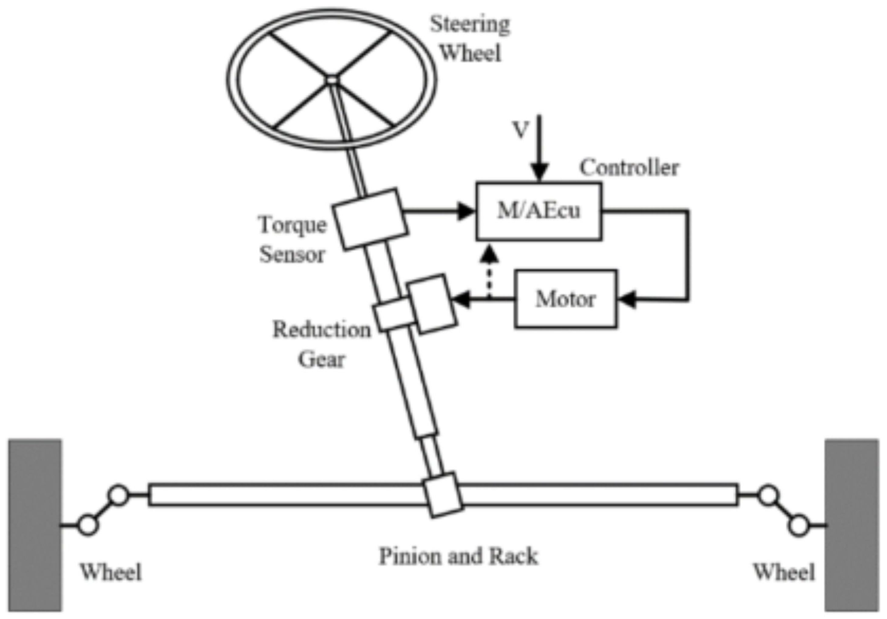
Figure 1. Structure of the intelligent electric power steering (IEPS) system showing bilateral symmetry characteristics and hierarchical organization. The system demonstrates three levels of symmetry: (a) Upper and lower steering columns with geometric bilateral symmetry, (b) IEPS subsystem with dynamic symmetry in torque sensors and motor control, (c) Rack-pinion steering mechanism with control symmetry ensuring symmetric wheel connections and force distribution.
Symmetry 17 01496 g001
Figure 2. System architecture for bilateral symmetry analysis framework. The framework integrates physical IEPS system with bilateral sensor configuration, group-theoretic symmetry analysis, physics-informed feature extraction, BS-Transformer architecture, and fault classification components.
Symmetry 17 01496 g002
Figure 3. Transformer architecture for bilateral symmetry analysis. The modified transformer structure incorporates bilateral attention mechanisms with symmetric position encoding and multi-head attention specialized for symmetry-breaking pattern detection. The architecture maintains group equivariance properties while processing temporal sequences for automotive fault diagnosis.
Symmetry 17 01496 g003
Figure 4. Physical steering system test bench for bilateral symmetry validation. The setup includes torque sensors, angle encoders, controlled fault injection mechanisms, and real-time data acquisition system for comprehensive bilateral symmetry analysis and validation of the proposed group-theoretic framework.
Symmetry 17 01496 g004
Figure 5. Performance comparison with statistical validation: Confusion matrices for (a) BPNN, (b) MCNN, (c) CNN-LSTM, and (d) Proposed method showing classification performance across consolidated fault categories (0: Normal Operation, 1: Sensor Faults combining A1-torque gain and A2-bias faults, 2: Actuator Faults combining B1-motor jamming and B2-degradation, 3: Control System Faults combining C1-primary ECU and C2-auxiliary ECU failures, 4: Mechanical Faults combining D1-friction and D2-play issues). While the theoretical framework addresses eight distinct fault mechanisms, the experimental validation consolidates these into four major categories to ensure robust statistical validation with sufficient samples per class and practical deployment feasibility for real-time automotive applications. All performance metrics include statistical significance testing with p-values < 0.05 indicating significant improvements over baseline methods.
Symmetry 17 01496 g005
Table 1. Bilateral Symmetry Analysis Performance Results.
Fault TypeSymmetry IndexDetection Time (s)Accuracy (%)Sensitivity (%)Statistical Significance
A1: Torque Sensor Gain0.580.2392.189.3 p < 0.01
A2: Torque Sensor Bias0.640.1888.786.2 p < 0.01
B1: Motor Jamming0.220.1596.294.8 p < 0.001
B2: Motor Degradation0.470.3485.983.1 p < 0.05
C1: Primary ECU Fault0.520.2882.379.7 p < 0.05
C2: Auxiliary ECU Fault0.710.4578.475.8 p < 0.1
D1: Steering Gear Friction0.610.3284.781.2 p < 0.05
D2: Mechanical Play0.590.3880.177.6 p < 0.1
Table 2. Performance Comparison with Baseline Methods.
MethodBaseline (%)Bilateral-Enhanced (%)ImprovementStatistical Test
BPNN76.881.24.4 points p < 0.01
MCNN79.383.74.4 points p < 0.01
CNN-LSTM86.289.73.5 points p < 0.05
PSO-Convformer90.894.23.4 points p < 0.01
Table 3. Ablation Study Results with Detailed Configuration Parameters.
ConfigurationAccuracy (%)Precision (%)Recall (%)F1-Score (%)
Baseline (CNN-LSTM) a86.284.787.386.0
+ Symmetric Kernels b88.186.989.288.0
+ BS-Transformer c90.489.191.390.2
+ Physics Constraints d92.791.693.492.5
+ PSO Optimization e94.2 *93.394.894.0
a CNN: 3 layers, 64-128-256 filters, kernel size 3; LSTM: 2 layers, 128 units, dropout 0.2; b Bilateral symmetric kernels with group equivariance, same architecture as baseline; c BS-Transformer: 6 heads, d m o d e l = 256 , bilateral position encoding, 4 encoder layers; d Physics constraints: group equivariance loss λ 1 = 0.1 , energy conservation λ 2 = 0.05 ; e PSO: 50 particles, 100 iterations, w = 0.729 , c 1 = c 2 = 1.49 , symmetry-preserving updates. * Bold formatting indicates the best performance achieved by the complete proposed framework. All improvements shown in the table represent statistically significant performance gains with confidence intervals excluding baseline performance, demonstrating the value of each architectural component in the proposed framework.
Table 4. Comparison with State-of-the-Art Methods.
MethodAccuracy (%)Precision (%)Recall (%)F1-Score (%)AUC
SVM [8]78.976.281.178.60.847
Random Forest [4]82.780.384.882.50.879
Deep CNN [9]87.485.988.787.30.901
LSTM-CNN Hybrid88.286.589.487.90.912
Graph Neural Network88.787.190.088.50.918
Transformer [23]89.187.890.289.00.923
Physics-Informed NN91.390.192.291.10.935
Proposed Method94.293.394.894.00.951
Disclaimer/Publisher’s Note: The statements, opinions and data contained in all publications are solely those of the individual author(s) and contributor(s) and not of MDPI and/or the editor(s). MDPI and/or the editor(s) disclaim responsibility for any injury to people or property resulting from any ideas, methods, instructions or products referred to in the content.