Abstract
To meet the in-orbit performance verification requirements of a drag-free control system for gravitational wave detection satellites, this study develops a ground simulation platform using the H-infinity () control method in Simulink. The FPGA implementation accelerates the core algorithm of drag-free control. A frequency-domain linear robust control design is employed, with a frequency pre-warped bilinear transformation method used to discretize the multi-degree-of-freedom controller. The established control system model includes 18 degrees of freedom, with 12 from the dual test masses (TM) and 6 from the satellite body. The two test masses are spatially arranged in a symmetric configuration, and their control structure also exhibits symmetry. A rapid reconfigurable hardware architecture is utilized, and the Vitis Model Composer tool is employed to efficiently translate the Simulink algorithm model into hardware description language, reducing the processing delay of the core control algorithm to the nanosecond level. Through a 15-channel gradient test comparison, the FPGA platform maintains numerical equivalence with the Simulink platform (maximum error of ). Experimental results show that the hardware acceleration improves dynamic response speed by an order of magnitude, achieving position control accuracy of ±5 μm and attitude accuracy of ±10 μrad, with overall processing latency at the microsecond level. This method provides a reliable engineering validation approach for ultra-precision control systems in gravitational wave detection.
1. Introduction
Gravity is a fundamental force of interaction between matter, and the detection of gravitational waves overcomes the limitations of electromagnetic wave observations, enabling the exploration of large-scale cosmic phenomena and extreme astrophysical events. Space-based gravitational wave detection works by capturing the distance changes induced by gravitational waves and then inversely calculating the related information about the waves [1,2,3,4]. However, gravitational waves are extremely weak, resulting in minuscule changes in distance. For example, the distance variation they induce is less than the diameter of an atom over a length of millions of kilometers.
In 1959, American physicist George Pugh first proposed the drag-free control system [5]. The core idea of drag-free control is for the satellite to actively track the test mass suspended inside, using microthrusters to counteract external disturbances, thereby achieving an “ultra-quiet and ultra-stable” state [6,7,8,9,10]. In 1972, the United States launched the first drag-free control technology verification satellite, TRIAD I, which demonstrated the feasibility of drag-free control satellites [11]. As shown in Figure 1, the diagram illustrates the drag-free control mode. A drag-free control platform typically consists of a satellite body and multiple test masses, which are symmetrically distributed in space. This symmetrical configuration helps balance the system’s mass distribution and inertial properties, thereby simplifying controller design, reducing coupling effects, and enhancing both system stability and the uniformity of response.
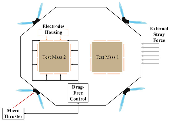
Figure 1.
Drag-free control operating mode.
Based on the aforementioned research background and in light of the challenges posed by the insufficient in-orbit performance of drag-free control systems in future gravitational wave detection satellite missions, ground simulation testing for verifying the performance of the drag-free control system becomes particularly important. Currently, ground-based simulation platforms include Sun Yat-sen University’s system, which uses the Stewart platform for kinematic and dynamic modeling and the design and construction of a drag-free ground simulation experimental setup. The system has successfully implemented drag-free control with two degrees of freedom. Experimental results show that, except at the inherent frequency point of the suspension system, the controller achieves a precision of less than 8 µm in the X-axis translation direction and less than 0.2 mrad in the Y-axis rotation direction [12]. The European Space Agency (ESA) and the Japan Aerospace Exploration Agency (JAXA) used a high-precision accelerometer (ISA) for the BepiColombo mission, employing a constrained multi-segment orbit determination method to complete the drag-free control ground simulation system for Mercury satellite simulation. Through numerical simulations, they identified a calibration method for the ISA data, effectively compensating for accelerometer errors and ensuring data reliability in the scientific target frequency band (1.2 × Hz), achieving simulation accuracy at the nanometer level [13]. In the LISA gravitational wave detection program jointly developed by NASA and the European Space Agency, a constrained decoupled control architecture was employed to construct a linearized state-space model with 20 degrees of freedom. High-fidelity verification was conducted using a Simscape model, achieving ground-based simulation validation at the sub-nanometer level [14].
However, the aboveground-based simulations are affected by ground vibrations and residual forces from air damping (ranging from ∼ N). Moreover, most air-floating platforms support only three to six degrees of freedom, making it difficult to replicate the complex multi-body coupled dynamics of space environments. To address the above issues, this study proposes a drag-free control hardware–software platform based on the Simulink simulation environment and the control method. The platform is capable of implementing drag-free control across 18 degrees of freedom, including 6 degrees of freedom for the satellite and 12 for the two test masses. The two test masses are symmetrically arranged with respect to the centers of their respective electrode housings. Their masses are closely matched, with a mismatch controlled within 5∼10%, and their deviations from the ideal positions are in the order of hundreds of micrometers. This symmetric configuration satisfies the system’s symmetry requirements, enabling algorithmic simplification and facilitating the implementation of coupled control. The platform achieves a position control accuracy of ±5 μm and an attitude accuracy of ±10 μrad. To ensure real-time performance, the drag-free control algorithm is deployed on an FPGA for testing, enabling parallel simulation of drag-free control with eighteen or more degrees of freedom. This implementation overcomes key limitations of software-based systems, such as poor parallelism and inadequate timing precision, reducing the overall processing latency to the microsecond level and significantly enhancing the system’s real-time capability.
2. Model Building
With its exceptional ability to achieve ultra-low disturbances, drag-free control technology has advanced rapidly in both theoretical and engineering domains. The Gravity Probe B (GP-B) satellite employed the LQR method to design its test mass suspension control system, with a classical PID controller serving as a backup [15]. LQR assumes a fully known system model; however, drag-free control systems are affected by sensor noise, the nonlinear characteristics of micro-thrusters, and uncertain external disturbances such as solar radiation pressure and gravity gradients. Consequently, LQR exhibits insufficient robustness against these perturbations. The European Space Agency designed the disturbance reduction system (DRS) of the LISA Pathfinder satellite based on the principles of PID control [16]. This approach requires separate tuning of the PID control parameters for 15 control loops, as well as high-order attenuation filters, and it is challenging to effectively utilize frequency-domain information. The Science and Technology on Space Intelligent Control Laboratory proposed an adaptive drag-free control law design based on setpoint identification using adaptive control. By introducing multiple thresholds within a constrained interval, the observed outputs are transformed into setpoint information corresponding to different thresholds, and an identification algorithm for unknown parameters is constructed based on these thresholds and weighted optimization techniques [17]. It allows for an online estimation of system parameters or disturbances, enabling the control of unknown systems. However, for drag-free control systems, high-precision position control requires sub-nanometer residual accelerations. If the parameter convergence is slow, errors may occur during the initial stage or under abrupt disturbances, resulting in suboptimal transient responses.
Given that the closed-loop control metrics of drag-free satellites are defined in the frequency domain, designing controllers in the frequency domain allows for global optimization of performance metrics, thereby efficiently achieving the control accuracy required for mission objectives. Leveraging its central role in robust control, control theory provides strong robustness and disturbance rejection by minimizing the norm of the system. The key advantage of this approach is its frequency-domain design framework, which offers explicit physical interpretation and is especially suited to meeting the high-precision control demands of drag-free satellites [18,19,20]. Accordingly, this study presents a Simulink-based implementation of a drag-free control algorithm grounded in robust control theory, with hardware acceleration achieved via FPGA.
The semi-physical simulation system for drag-free control consists of a high-precision sensing module, a filtering module, a core control algorithm module, and a command execution module. The high-precision sensing module monitors the relative position between the test mass and the spacecraft in real time. This task is primarily handled by the gravitational reference sensor (GRS), which acquires both the position and attitude of the test mass. The collected data are transmitted to the Kalman filtering module, which includes both prediction and update submodules. Based on the system dynamics model, the prediction module estimates the state at the next time step, while the update module balances the weights of prediction and observation to minimize estimation error. The filtered results are then passed to the core drag-free control algorithm module, where control commands are generated and sent to the next stage, as illustrated in Figure 2. This study focuses on the implementation of the drag-free control core algorithm on the Simulink platform and its acceleration using FPGA-based hardware.
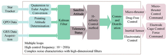
Figure 2.
Overall architecture of the drag-free control hardware-in-the-loop simulation system.
The core drag-free control algorithm is designed using a frequency-domain linear robust control approach, with theoretical analysis and implementation based on the control method. This method synthesizes the magnitude frequency characteristics of the closed-loop sensitivity function S, the complementary sensitivity function T, and the product of the controller transfer function and sensitivity function KS, thereby deriving a controller transfer function K that meets the required performance specifications [21,22].
2.1. Control Method
The design of the control method primarily addresses the tracking control problem of linear systems, as illustrated in Figure 3. In this framework, represents the control input, y is the measured output, is the disturbance input, and z is the controlled output. The transfer function matrix from the inputs and to the outputs z and y, denoted as G(s), is referred to as the augmented plant. It includes both the actual plant and additional weighting functions introduced to represent design specifications. K(s) denotes the controller [23,24].
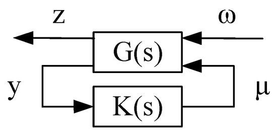
Figure 3.
Tracking control example for a linear system.
Let the state-space realization of the transfer function matrix G(s) be given by
In Equation (1), x is an n-dimensional state vector, is an r-dimensional disturbance vector, u is a p-dimensional control input vector, z is an m-dimensional controlled output vector, and y is a q-dimensional measured output vector. The above equation can therefore be rewritten in matrix form as
The closed-loop transfer function from to z is given by
The theoretical core of this method lies in establishing constraints on three categories of transfer functions. The magnitude frequency characteristics of the sensitivity function S are constrained to ensure the system’s disturbance rejection capability; the complementary sensitivity function T is constrained to guarantee robust stability; and the magnitude frequency characteristics of the transfer function K(s) are constrained to limit the dynamic behavior of the actuators [25,26].
At the engineering implementation level, weighting functions are introduced to shape the magnitude frequency characteristics of the aforementioned transfer functions, forming a mixed sensitivity optimization problem. The optimal controller parameters are then obtained by solving the standard control problem.
2.2. Drag-Free Control Model
When implementing the control method using hardware circuits, the inherent digital nature of such systems necessitates the discretization of the continuous-time controller to enable realization within a digital control framework. The basic idea is to first design an analog controller in the continuous-time domain that meets the required control performance and then convert it into a digital controller through an appropriate approximation method [27,28]. This approach generally requires a sufficiently small sampling period; the smaller the sampling period, the closer the discrete system approximates the behavior of the original continuous system.
In the drag-free control algorithm module, the controllers for TM1 along the x-axis (TM1−x) and TM2 along the x-axis (TM2−x) are discretized using the frequency prewarped bilinear transformation method, while the controller for TM1 along the z-axis (TM1−z) is implemented using the standard bilinear transformation method. After discretization, the transfer functions of the respective controllers are given as follows:
TM1−x, TM2−x:
The transfer function of controller K1 is defined as the ratio of the Laplace transform of the output signal to that of the input signal for TM1 and TM2 along the x-axis.
TM1−z:
The transfer function of controller K2 is defined as the ratio of the Laplace transform of the output signal to that of the input signal for TM1 along the z-axis.
The attitude control loop algorithm module is discretized using the bilinear transformation method, which effectively preserves the system’s stability and dynamic characteristics. Under zero-delay conditions, the transfer function models of the controller system are derived theoretically.
In the discretization design of the electrostatic suspension control loop, symmetry coupling is applied with reference to Equations (4) and (5) under the no-delay condition. The controllers for TM1 along the y-axis (TM1−y) and TM2 along the y-axis (TM2−y) are discretized using the frequency prewarped bilinear transformation method, while the controller for TM2 along the z-axis (TM2−z) adopts the standard bilinear transformation method. The controllers for all remaining degrees of freedom are discretized using the frequency prewarped bilinear transformation approach. This method enables the discretization of the control method to accommodate digital control systems.
3. Simulation Design and Implementation
The core objective of control is to minimize the impact of external disturbances on the system while ensuring overall stability [25,26,27]. In this study, the control method is implemented on both the Simulink simulation platform and an FPGA-based hardware platform. An ideal simulation environment is constructed to provide high-precision modeling, while hardware acceleration is employed to enhance the algorithm’s real-time processing capabilities. The drag-free control simulation system is realized in Simulink, enabling a fully integrated workflow, rapid algorithm iteration, and seamless hardware deployment. With built-in modules and automatic code generation tools, the closed loop from theoretical design to engineering validation is efficiently achieved. Furthermore, the high computational capability of the FPGA enables oversampling of the input signals, thereby enhancing the control accuracy of the drag-free control algorithm.
The rapid reconfigurable hardware implementation of the control algorithm model via the MATLAB (R2019b)/Simulink platform addresses the long development cycles and high complexity commonly associated with traditional FPGA development, which stem from hardware parallelism, resource constraints, and low-level logic design. The FPGA-based semi-physical simulation platform for drag-free control overcomes the limitations of conventional controllers in timing precision and multi-channel parallel processing. As a result, a high-precision ground-based semi-physical simulation platform has been successfully established to support ultra-sensitive weak-force measurement.
3.1. Based on Simulink
3.1.1. Simulation Design Based on Simulink
Based on the control method, a “strong-following” motion of the spacecraft simulation platform with respect to the test mass is realized under free-fall mode, while a “weak-following” mechanism of the test mass relative to the platform is established under active vibration isolation mode. Based on this mechanism, a drag-free control system simulation model is constructed using the Simulink platform.
The simulation platform comprises a total of 18 degrees of freedom. These include the sensitive axis directions of the dual-test mass system and the direction perpendicular to the optical axis plane of one test mass, where displacement-based drag-free control is applied. The remaining nine degrees of freedom are controlled via electrostatic suspension to achieve coordinated motion between the test masses and the electrode cage. Additionally, six degrees of freedom correspond to the satellite’s motion; among these, the three translational motions of the satellite are outcomes of the drag-free control and are not actively controlled within the closed-loop system and thus are neglected. The core drag-free control module based on Simulink is illustrated in Figure 4.
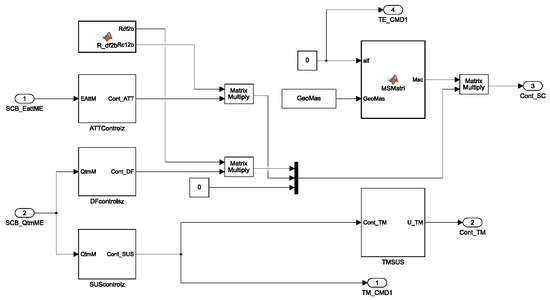
Figure 4.
Implementation of the core module of the drag-free control system in Simulink.
- The core drag-free control module also includes the following inputs: SCB_EattME, representing the satellite attitude error angles, and SCB_QtmME, representing the filtered 12-degree-of-freedom state variables of the two test masses.
- The outputs of the core drag-free control module include Cont_SC, which provides the drag-free control forces for the three degrees of freedom of the two test masses, as well as the satellite’s attitude pointing (three degrees of freedom) relative to a reference frame, and Cont_TM, which represents the electrostatic control forces for the remaining nine degrees of freedom of the test masses.
- Core control functions of the drag-free control module:
- -
- Inputs:SC_STATE: The physical input variable for a single degree of freedom of the satellite at time step n.xn: The state vector corresponding to the state-space representation at time step n (initialized to zero).A, B, C, D: The discrete-time state-space coefficient matrices derived from the transfer function for the corresponding degree of freedom.
- -
- Basic Control Function:Computes the control force along the corresponding rotational axis by processing the single-degree-of-freedom state input of the satellite at time step n.
- -
- Outputs:yn: The control force in the direction of the corresponding degree of freedom at time step n.xn: The updated state vector in the state-space model at time step n, which serves as the input state for calculations at time step n + 1.
- -
- Detailed Algorithm:The current input estimation error is denoted as un. Compute the output control force as
- -
- State Update:This function is implemented in the Simulink model using the Discrete State-Space block. The Discrete State-Space block represents a system described by the following equations:where u denotes the input, x the state vector, and y the output.
3.1.2. Modeling and Implementation Based on Simulink
To simplify the control of the entire loop, it is essential to analyze its driving factors. Each controller is designed to meet the closed-loop performance requirements within the scientific measurement bandwidth while also ensuring sufficient gain and phase margins across appropriate variations in the transfer function, including gain and stiffness.
The following presents a decomposition of the complete force and torque system acting on the satellite and the two test masses:
- Inputs acting on the spacecraft: FEEP thrust noise, solar radiation pressure and associated torque noise, and the reaction forces and torques induced by the test masses (resulting from electrostatic suspension actuation).
- Inputs acting on the test masses: electrostatic suspension control forces and torques, noise introduced by the electrostatic suspension actuation, and forces and torques resulting from the coupling between the spacecraft and the test masses, such as those induced by stiffness.
The following provides an analysis of the control loops acting on the spacecraft and the two test masses:
- The primary functions driving the spacecraft attitude control loop include shielding the test masses from external disturbances, reducing spacecraft attitude jitter by suppressing noise, managing control loop time delays, and accommodating variations in transfer function gain and phase margins.
- The primary objectives of the suspension control loop are stabilizing the non-drag-free coordinates of the test masses, which exhibit inherent negative stiffness, reducing test mass jitter caused by noise suppression, managing control loop time delays, and maintaining gain and phase margins in the presence of variations in transfer function gain and pole locations.
The control model of the entire system loop is shown in Figure 5.
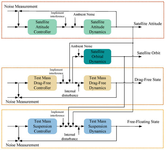
Figure 5.
Closed-loop control block diagram of the entire drag-free control system.
Taking the satellite roll angle control algorithm within the satellite attitude error as an example, the drag-free control process is designed using the Discrete State-Space block. The core of this approach is to convert the satellite roll angle error into an output force along the roll axis. The inputs include SCB_EattME(0), which is the satellite roll angle error, xn, which is the corresponding state variable in the roll angle control state-space representation (initialized to zero), and KSC.ztxA, KSC.ztxB, KSC.ztxC, and KSC.ztxD, which are the discrete state-space coefficient matrices derived from the roll axis control transfer function. By applying the basic control function Control_SC, the outputs obtained are Cont_ATT(0), which is the satellite roll axis output force, and xn, which is the updated state variable in the state-space representation. The drag-free control processes for the other degrees of freedom are similar to the satellite roll angle control algorithm.
The drag-free control model was constructed in MATLAB/Simulink. Based on the noise characteristics described in reference [26], the model simulates the required noise signals through numerical simulation, including actuator noise, dynamic noise, and sensor noise, which serve as inputs for the system simulation. Figure 6 illustrates the simulated input noise signals.

Figure 6.
Typical noise sources in the drag-free control system. (a) Actuation-related noise including temperature-induced noise, mechanical vibration noise, and acceleration noise introduced by the electrostatic suspension system. (b) System dynamics noise such as solar radiation pressure noise and inherent physical noise. (c) Sensor noise arising from the measurement devices used in the drag-free control system.
Since the satellite’s three translational motions are outcomes of the drag-free control and are not actively controlled within the closed-loop system, they are omitted from the control loop. As a result, 15 simulated noise signals are generated, as shown in Figure 7a, to drive the remaining 15 degrees of freedom in the control simulation platform. The resulting drag-free control outputs are shown in Figure 7b.

Figure 7.
Simulation data related to the drag-free control system. (a) Satellite attitude angle errors and physical input quantities across all degrees of freedom. (b) Output results of the semi-physical simulation system for drag-free control based on Simulink.
Since all performance requirements are specified in terms of spectral density, the simulation results demonstrate that the designed controller effectively achieves drag-free control along the designated axis. The resulting noise spectral density remains below the relative jitter requirement, with position control accuracy reaching ±5 μm and attitude control accuracy reaching ±10 μrad.
3.2. Based on FPGA
The Zynq UltraScale+ MPSoC EG series, developed by Xilinx, is a high-performance heterogeneous multiprocessor system-on-a-chip (MPSoC) that integrates ARM multi-core processors, a field-programmable gate array (FPGA), and dedicated hardware acceleration units. It offers significant advantages in parallel processing, memory architecture, and computational performance. In this study, the Xilinx XCZU19EG-2FFVC1760I chip is employed to implement FPGA-based multi-channel drag-free control, data processing, command distribution, external communication, and the control and management of various memory devices.
Using an FPGA as the hardware platform for the core drag-free control algorithm can significantly enhance computational efficiency. Its integrated configurable logic blocks (CLBs) and look-up tables (LUTs) support hardware-level multi-instruction stream parallel processing, efficiently handling operations that involve large-scale multiply-accumulate tasks, such as fast Fourier transforms and digital filtering, thereby substantially improving computation speed and dynamic response. In terms of system stability, the FPGA logic architecture is built on deterministic timing circuits and does not rely on operating system task scheduling, making task execution time and response latency highly predictable. Additionally, its real-time status monitoring capability ensures reliable and consistent performance during long-term operation. Furthermore, FPGA allows for a flexible configuration of logic structures, data paths, and interface protocols, enabling the expansion of processing capacity through additional functional modules or deeper pipelines. Multiple control modules and communication interfaces can also be integrated within a single chip, demonstrating strong potential for system scalability.
3.2.1. Rapid Reconfigurable Technology
The Vitis Model Composer, a model-based design tool, is employed to implement rapid reconfigurable technology. Its core feature lies in the automatic generation of hardware implementation code from algorithmic models, enabling seamless integration from system simulation to hardware deployment, as illustrated in Figure 8. This tool operates within the MathWorks MATLAB and Simulink environments, supporting rapid design and automatic generation of hardware description language (HDL) code. With the deployment of this tool, control algorithm models developed in MATLAB/Simulink can be imported to the FPGA platform for hardware-level verification and design, thereby enabling both data computation and system control.
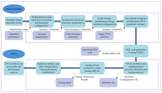
Figure 8.
Flowchart of FPGA hardware-in-the-loop testing implemented via Simulink model configuration using Vitis Model Composer.
The use of rapid reconfigurable technology to generate HDL code is primarily intended for early-stage rapid verification, resource utilization assessment, and preliminary execution time testing. This approach can significantly shorten the conversion cycle from Simulink models to FPGA implementation, thereby improving development efficiency. The automatically generated HDL code is largely implemented using combinational logic, which facilitates subsequent synthesis and optimization. Compared with sequential logic, combinational logic consumes more resources but achieves higher computational speed, effectively trading additional resources for faster execution. The automatically generated HDL code also demonstrates good adaptability in cross-clock-domain designs, reducing the complexity and effort of manual intervention. As a result, it not only meets current design requirements but also offers strong maintainability and scalability. For the final deployment version, manual optimization should be applied on top of the automatically generated code to further enhance system performance and resource utilization, balancing resource consumption and execution time to satisfy stricter requirements for real-time operation and power efficiency.
When implementing rapid reconfigurable technology based on Simulink algorithms, it is essential to address the timing model of the system clock to eliminate interference across clock domains. A globally synchronized reset signal architecture must be configured. In this study, a high-level triggered asynchronous reset scheme is adopted. The drag-free control core algorithm is implemented using the Xilinx XCZU19EG-2FFVC1760I chip. During the configuration process, careful attention must be paid to parameter settings, interface specifications, and other key configuration parameters. Finally, the makehdl command is used to generate RTL-level Verilog code.
3.2.2. Design Base on FPGA
Using the rapid reconfigurable design capabilities of Vitis Model Composer, the drag-free control core algorithm is translated from a high-level software description to HDL. The algorithm is then synthesized on the Vivado (2019.1) platform, resulting in the hardware circuit diagram of the drag-free control core, as shown in Figure 9.
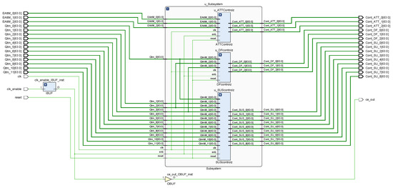
Figure 9.
Schematic diagram of the synthesized circuit for the core algorithm of drag-free control.
- The inputs to the drag-free core control module include EAttm_0-2, representing the satellite attitude angle errors, and Qtm_0-11, representing the filtered 12-degree-of-freedom state variables of the two test masses.
- The outputs of the drag-free core control module include Cont_Att_0-2, representing the satellite attitude control forces, Cont_DF_0-2, the drag-free control forces, and Cont_SU_0-8, the electrostatic control forces corresponding to the remaining nine degrees of freedom of the test masses.
- The core control function module of the drag-free control system includes a subsystem composed of three components, namely u_ATTControlZ (attitude control), u_DFControlZ (drag-free degree-of-freedom control), and u_SUSControlZ (electrostatic suspension). These modules collectively enable the implementation of the drag-free control core algorithm in a hardware environment.
The resource utilization of the synthesized core algorithm is summarized in Table 1.

Table 1.
Resource utilization.
This design implements the drag-free control algorithm on the Xilinx XCZU19EG-2FFVC1760I chip. As shown in Table 1. The resource utilization is as follows: approximately 63.2% of LUTs and 20% of flip-flops (FFs) are occupied, demonstrating a reasonable hardware mapping efficiency. The core algorithm involves extensive matrix multiplications and filtering operations, with DSP block utilization around 50%, fully leveraging the FPGA hardware multiply-accumulate acceleration capabilities. The usage of internal block RAM is minimal, primarily for storing state variables and parameters, which has not been analyzed in detail. The relatively high utilization of LUTs directly reflects that the HDL code generated using rapid reconfigurable technology is primarily composed of combinational logic. This implementation approach leverages resource and power costs to achieve higher computational speed, aligning with the trade resources for performance strategy adopted in the earlier design phase.
As shown in Table 2. According to power estimates obtained using the Vivado power analysis tool, the total on-chip power consumption is approximately 5.1 W. Dynamic power dominates at about 4.89 W, accounting for 95.89% of the total. Static power is approximately 0.21 W, accounting for 4.11% of the total. Overall, although the total power consumption is relatively moderate, this outcome is consistent with the trading resources for performance strategy adopted during the early design stage. Therefore, the proposed approach offers valuable reference potential for scenarios with stringent performance requirements.

Table 2.
On-chip power consumption.
Regarding timing, a comprehensive analysis of the maximum delay path based on Vivado timing reports shows a timing requirement of 20.429 ns. Additionally, the clock setup slack and hold slack are 14.143 ns and 0.054 ns, respectively, with a pulse width slack of 0.750 ns. Test results show that the timing jitter variance is less than 10−12 s2, and the maximum delay deviation is less than 5% of the clock period. The timing analysis indicates that the core algorithm predominantly relies on combinational logic, and the strategy of trading resource usage for speed has significantly enhanced the execution speed of the drag-free control core algorithm.
3.2.3. Modeling and Implementation Based on FPGA
In MATLAB/Simulink, the To Workspace Block is used to export the simulated noise signals generated by the Simulink model to the MATLAB workspace, where they are saved as programmable variables—such as SCB_ActuN, SCB_DynaN, and SCB_SensN, as shown in Figure 6. Since floating-point signal processing is relatively slow on FPGA hardware, the exported simulated noise signals are quantized and converted into a 16-bit fixed-point format suitable for FPGA computation. On the Vivado platform, these fixed-point signals are then used as inputs to the drag-free control core algorithm, implemented via rapid reconfigurable techniques, to evaluate the performance of the algorithm on the FPGA platform. The overall process is illustrated in Figure 10.
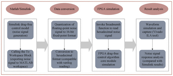
Figure 10.
Test procedure based on FPGA simulation results.
A file-based data exchange method was used in the Vivado test bench, where the $readmemh system task was invoked to load simulated noise signals as excitation inputs to the drag-free control core algorithm for simulation testing. The overall timing simulation results of the drag-free control algorithm are shown in Figure 11.
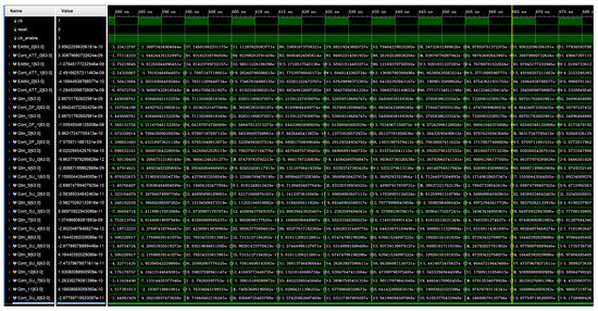
Figure 11.
Overall timing simulation results of the drag-free control algorithm based on FPGA.
4. Discussion
By analyzing the data processing capability and control accuracy of the drag-free control simulation implemented concurrently on Simulink and FPGA platforms, the performance of the FPGA-based drag-free control hardware-in-the-loop simulation can be evaluated. Under identical input noise signal conditions, this evaluation is performed by comparing the control outputs of the drag-free control algorithm module with the numerical simulation results obtained from the Simulink platform.
4.1. Parallel Data Processing
To evaluate the differences in parallel computing performance between the Simulink and FPGA-based drag-free control hardware-in-the-loop simulation systems, a gradient testing method was employed. By progressively reconstructing the task topology, the control algorithm loop was expanded from a single channel to a 15-channel parallel architecture. The experiment recorded the system’s single-cycle computation latency at each level through a real-time monitoring module, establishing a quantitative model relating the parallel architecture to real-time performance metrics.
As shown in Figure 12, the runtime of the Simulink-based drag-free control core algorithm increases with the number of input noise channels, with computation times on the millisecond scale. The algorithm’s average execution time is 0.1416 s, and the timing stability is characterized by a variance of 2.0689 × 10⁻⁴ s2 and a standard deviation of 0.0144 s. These quantitative results reveal the timing fluctuation characteristics of the algorithm operating in a non-real-time system environment. In contrast, the FPGA-based drag-free control core algorithm maintains stable runtime as the number of input noise channels increases, with computation times on the nanosecond scale. This demonstrates that the use of FPGA can effectively enhance the real-time computational capability of the drag-free control core algorithm.
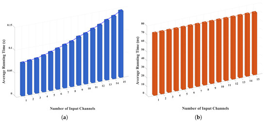
Figure 12.
Comparison of average execution times for multi-channel drag-free control algorithms. (a) Average execution time of the multi-channel drag-free control algorithm based on Simulink. (b) Average execution time of the multi-channel drag-free control algorithm implemented on FPGA.
4.2. Accuracy Comparison Analysis
Using the MATLAB platform, the output results from the Simulink and FPGA platforms were compared under identical input noise conditions. The actual drag-free control results were captured using an integrated logic analyzer (ILA). In the Vivado test bench file, the $fwrite function was used to store the simulation output as hexadecimal data in a binary file. On the MATLAB platform, the fopen function was used to read the binary file, extract the raw byte data, decode it into numerical values, and reconstruct the time axis for comparison with the Simulink output.
A comparative analysis was conducted on the output results of the drag-free control hardware-in-the-loop simulation systems implemented on FPGA and Simulink platforms under identical input conditions. As shown in Figure 13, steady-state output data were collected after 200, 5000, 10,000, and 20,000 drag-free control cycles. The experimental results clearly demonstrate that the red circles representing the Simulink-based outputs and the blue asterisks representing the FPGA-based outputs exhibit a high degree of overlap. This indicates strong consistency in the error convergence characteristics between the two implementation approaches.
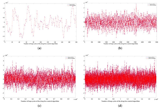
Figure 13.
Comparison of drag-free control results based on simulink and FPGA implementations at different cycle counts. (a) Result comparison after 200 cycles. (b) Result comparison after 5000 cycles. (c) Result comparison after 10,000 cycles. (d) Result comparison after 20,000 cycles.
To thoroughly evaluate the consistency between the two matrix outputs produced by different implementations of the drag-free control algorithm, a comprehensive difference analysis was conducted, as illustrated in Figure 14. Panel (a) displays the element-wise signed difference curve, which reveals both the direction and trend of fluctuations between corresponding elements in the two matrices. This provides insight into whether deviations tend to be positive or negative over the data set. Panel (b) presents the absolute difference values, offering a clear and intuitive representation of the magnitude of numerical discrepancies without regard to their sign, thereby emphasizing the size of deviations. Panel (c) shows the histogram distribution of the difference values, demonstrating that the majority of deviations are tightly clustered around zero, which strongly indicates a high degree of overall agreement between the two outputs. Lastly, panel (d) depicts the cumulative distribution function (CDF) of the differences, quantitatively illustrating the statistical concentration and stability of these deviations across all matrix elements. Collectively, these analyses confirm that the numerical differences between the software- and hardware-based implementations remain within an acceptable tolerance, thereby validating the accuracy and reliability of the FPGA realization of the drag-free control algorithm.
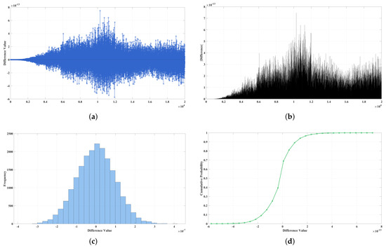
Figure 14.
Comprehensive analysis of element-wise differences between two result matrices. (a) Signed difference curve. (b) Absolute difference magnitude. (c) Histogram of value distribution. (d) Cumulative distribution function (CDF) illustrating statistical concentration.
5. Conclusions
By formulating the system’s dynamic equations based on symmetry, the control strategy achieves consistency across multiple degrees of freedom, thereby enabling coordinated multi-axis control. Moreover, symmetry helps ensure an even distribution of control and compensation forces, effectively reducing control errors and structural vibrations. Furthermore, comparative analysis with the Simulink simulation platform demonstrates that the FPGA architecture, optimized using hardware description language, exhibits excellent consistency in control accuracy, further validating the effectiveness of the system design. Compared with conventional implementations, this approach significantly enhances the dynamic response speed and timing precision of the drag-free control semi-physical simulation system while maintaining control accuracy. Overall, the hardware-based implementation shows substantial advantages over traditional simulation platforms, clearly demonstrating its value for engineering applications. With the continuous development of drag-free control system actuators, such as micro-thrusters, the latency requirements for the core drag-free control algorithm are expected to increase. In this study, a ground-based hardware-in-the-loop drag-free control system is established, providing a valuable technical reference for the future application of this algorithm in actual satellites. In addition, FPGAs offer excellent scalability, providing a practical solution for future control tasks with higher degrees of freedom and a greater number of test masses.
Author Contributions
Conceptualization, A.L., W.W. and Y.C.; methodology, P.W. and M.P.; validation, D.L. and L.X.; formal analysis, J.Y. and D.L.; investigation, A.L. and W.W.; resources, M.P. and P.W.; data curation, W.W. and Y.C.; writing—original draft preparation, A.L.; writing—review and editing, L.X. and J.Y.; visualization, W.W. and J.Y.; supervision, J.Y.; project administration, P.W.; funding acquisition, M.P. All authors have read and agreed to the published version of the manuscript.
Funding
This study was supported by the National Key R&D Program of China (2020YFC2200602), the Major Science and Technology Project of Shenzhen Municipality (KJZD20230923113903008), and the Peacock Team Talent Special Program of Shenzhen Municipality (KQTD20230301092838002).
Data Availability Statement
The original contributions presented in this study are included in the article. Further inquiries can be directed to the corresponding authors.
Conflicts of Interest
The authors declare no conflicts of interest.
Abbreviations
The following abbreviations are used in this manuscript:
| LISA | Laser Interferometer Space Antenna |
| GRS | Gravitational Reference Sensor |
| FPGA | Field-Programmable Gate Array |
| TM | Test masses |
| LQR | Linear Quadratic Regulator |
| DRS | Disturbance Reduction System |
| PID | Proportional–Integral–Derivative |
| FEEP | Field Emission Electric Propulsion |
| HDL | Hardware Description Languag |
| CLB | Configurable Logic Blocks |
| LUT | Look-Up Tables |
| FF | Flip-Flop |
| RAM | Random Access Memory |
| RTL | Register Transfer Level |
| ILA | Integrated Logic Analyze |
| CDF | Cumulative Distribution Function |
References
- Hu, Y.; Wang, P.; Tan, Y.; Shao, C. Bayesian analysis of the stochastic gravitational-wave background with alternative polarizations for space-borne detectors. Phys. Rev. 2024, 107, 24–26. [Google Scholar] [CrossRef]
- Crosta, M.; Lattanzi, M.; Poncin-Lafitte, C.; Gai, M.; Qi, Z.; Vecchiato, A. Pinpointing gravitational waves via astrometric gravitational wave antennas. Sci. Rep. 2024, 14, 5074. [Google Scholar] [CrossRef] [PubMed]
- Yang, B.; Liu, L.; Wu, S.; Li, H.; Zhou, Z. A low frequency horizontal active vibration isolation bench for testing the performance of high-precision space inertial sensors. Class. Quantum Grav. 2021, 38, 175006. [Google Scholar] [CrossRef]
- Danzmann, K.; LISA Science Team. LISA-An ESA cornerstone mission for the detection and observation of gravitational waves. Adv. Space Res. 2003, 32, 1233–1242. [Google Scholar] [CrossRef]
- Pugh, G. Proposal for a satellite test of the coriolis prediction of general relativity. In Nonlinear Gravitodynamics; World Scientific Publishing: Singapore, 2003; pp. 414–426. Available online: https://einstein.stanford.edu/content/sci_papers/papers/Pugh_G_1959_109.pdf (accessed on 1 January 2025).
- Li, Y.; Wang, C.; Wang, L.; Liu, H.; Jin, G. A Laser Interferometer Prototype with Pico-Meter Measurement Precision for Taiji Space Gravitational Wave Detection Missionin China. Microgravity Sci. Technol. 2020, 32, 331–338. [Google Scholar] [CrossRef]
- Armano, M.; Audley, H.; Auger, G.; Baird, J.; Bassan, T.; Bassan, M.; Binetruy, P.; Born, M.; Bortouzzi, D.; Brandt, N. Sub-femto-g free fall for space-based gravitational wave observatories: LISA pathfinder results. Phys. Rev. Lett. 2016, 116, 231101. [Google Scholar] [CrossRef]
- Binns, D.; Rando, N.; Cacciapuoti, L. The fundamental physics explorer: An ESA technology reference study. Adv. Space Res. 2009, 43, 1158–1170. [Google Scholar] [CrossRef]
- Amaro-Seoane, P.; Andrews, J.; Sedda, M.; Askar, A.; Baghi, Q.; Balasov, R.; Bartos, I. Astrophysics with the Laser Interferometer Space Antenna. Living Rev. Relativ. 2023, 26, 2. [Google Scholar] [CrossRef]
- Luo, Z.; Guo, Z.; Jin, G.; Wu, Y.; Hu, W. A brief analysis to Taiji: Science and technology. Results Phys. 2020, 16, 102918. [Google Scholar] [CrossRef]
- Snyder, N.; Williams, W.; Denton, D. A satellite freed of all but gravitational forces:“TRIAD I”. J. Spacecr. Rocket. 1974, 11, 637–644. [Google Scholar] [CrossRef]
- Lin, J.; Lian, J.; Zhao, G.; Li, H.; Xu, C. A 2-DOF drag-free control ground simulation system based on Stewart platform. ISA Trans. 2024, 146, 528–540. [Google Scholar] [CrossRef]
- Filippis, U.; Lefevre, C.; Lucente, M.; Magnafico, C.; Santoli, F.; Cappuccio, P.; Stefano, I.; Zurria, A.; Less, L. Pseudo-drag-free system simulation for bepicolombo radio science using accelerometer data. J. Guid. Control Dyn. 2024, 47, 685–696. [Google Scholar] [CrossRef]
- Vidano, S.; Pagone, M.; Grzymisch, J.; Preda, V.; Novara, C. drag-free and Attitude Control System for the LISA Space Mission: An H∞ Constrained Decoupling Approach. IEEE Trans. Control Syst. Technol. 2024, 32, 2149–2163. [Google Scholar] [CrossRef]
- Li, Z.; Bencze, W.; DeBra, D.; Hanuschak, G.; Holmes, T.; Keiser, G.; Mester, J.; Shestople, P.; Small, H. On-orbit performance of Gravity Probe B drag-free translation control and orbit determination. Adv. Space Res. 2007, 40, 1–10. [Google Scholar] [CrossRef]
- Peiman, G.; James, R.; Oscar, H.; John, K.; Charles, E. Drag-free performance of the ST7 disturbance reduction system flight experiment on the LISA pathfinder. In Proceedings of the International ESA Conference on Guidance, Navigation and Control Systems, Salzburg, Austria, 29 May–2 June 2017; Volume 41, p. 406. Available online: https://ntrs.nasa.gov/citations/20170004848 (accessed on 1 April 2025).
- Tan, S.; Guo, J.; Zhao, Y.; Zhang, J. Adaptive control with saturation-constrainted observations for drag-free satellites-a set-valued identification approach. Sci. China Inf. Sci. 2021, 64, 202202. [Google Scholar] [CrossRef]
- Fan, Y.; Wang, P.; Lu, W.; An, K.; Zhang, Y. Robust controller design for drag-free satellites with two test masses. J. Deep Space Explor. 2023, 10, 310–321. [Google Scholar]
- Ma, H.; Han, P.; Gao, D.; Zheng, J. H∞ robust controller design for deep space drag-free satellite with two test masses. J. Harbin Inst. Technol. 2021, 53, 1–13. [Google Scholar]
- Xu, Q.; Cui, B.; Wang, P.; Xia, Y.; Zhang, Y. Finite Frequency Domain H∞ Hybrid Control Design of drag-free Spacecraft with Model-based Generalized Extended State Observer. Control Eng. Pract. 2024, 153, 106096. [Google Scholar] [CrossRef]
- Canuto, E. drag-free and attitude control for the GOCE satellite. Automatica 2008, 44, 1766–1780. [Google Scholar] [CrossRef]
- Guo, Z. Standard siren cosmology with the LISA-Taiji network. Sci. China Phys. Mech. Astron. 2022, 64, 210431. [Google Scholar] [CrossRef]
- Vidano, S.; Novara, C.; Pagone, M.; Grzymisch, J. The LISA DFACS: Model predictive control design for the test mass release phase. Acta Astronaut. 2022, 193, 731–743. [Google Scholar] [CrossRef]
- Zhao, J.; Mili, L. A theoretical framework of robust H-infinity unscented Kalman filter and its application to power system dynamic state estimation. IEEE Trans. Signal Process. 2019, 67, 2734–2749. [Google Scholar] [CrossRef]
- Lin, C.; Mu, H.; Xiong, R.; Shen, W. A novel multi-model probability battery state of charge estimation approach for electric vehicles using H-infinity algorithm. Appl. Energy 2016, 166, 76–83. [Google Scholar] [CrossRef]
- Bergeling, C.; Pates, R.; Rantzer, A. H-infinity optimal control for systems with a bottleneck frequency. IEEE Trans. Autom. Control 2020, 66, 2732–2738. [Google Scholar] [CrossRef]
- Azizpour, M.; Raoufi, R.; Kazeminezhad, E. Investigation of the Robust H-Infinity Filter’s Effectiveness on the Model Predictive Control and Linear Quadratic Regulator for Active Seismic Control of High-Rise Buildings. Iran. J. Sci. Technol. Trans. Civ. Eng. 2020, 48, 923–941. [Google Scholar] [CrossRef]
- Cirillo, F. Controller Design for the Acquisition Phase of the LISA Mission Using a Kalman Filter. Master’s Thesis, University of Pisa, Pisa, Italy, 2007. Available online: https://core.ac.uk/download/pdf/14694048.pdf (accessed on 15 May 2025).
Disclaimer/Publisher’s Note: The statements, opinions and data contained in all publications are solely those of the individual author(s) and contributor(s) and not of MDPI and/or the editor(s). MDPI and/or the editor(s) disclaim responsibility for any injury to people or property resulting from any ideas, methods, instructions or products referred to in the content. |
© 2025 by the authors. Licensee MDPI, Basel, Switzerland. This article is an open access article distributed under the terms and conditions of the Creative Commons Attribution (CC BY) license (https://creativecommons.org/licenses/by/4.0/).