Abstract
Ultra-High Performance Concrete (UHPC), characterized by its superior mechanical properties and excellent durability, has emerged as a promising material for the repair and reinforcement of tunnels. This study aimed to clarify the reinforcement mechanism of UHPC for tunnel linings and the improvement in bearing capacity through numerical simulation and theoretical derivation. By simulating normal concrete (NC) and reinforced concrete (RC) eccentrically loaded columns under varying reinforcement configurations and working conditions, the study investigated the failure modes and mechanical behaviors of UHPC-reinforced tunnels. Analytical equations for the compression-bending capacity of UHPC-reinforced columns under secondary loading were established and validated. Subsequently, the influence of key parameters was systematically analyzed. The results show that UHPC reinforcement significantly enhances load-bearing capacity, deformation resistance, stiffness, and ductility, albeit with varying failure modes. Notably, the ultimate load-carrying capacity increases by up to 184.6% for NC columns at 180 mm eccentricity and 286.5% for RC columns at 200 mm eccentricity. Reinforcement effectiveness is highly influenced by eccentricity: inner-side reinforcement proves more advantageous under small eccentricities, whereas outer-side reinforcement outperforms under large eccentricities. Comparative analyses of various parameters reveal that initial strain has the greatest impact on reinforcement effectiveness, followed by UHPC thickness, UHPC strength, and the reinforcement ratio of the reinforcement layer, in descending order of influence. The research provides valuable insights into the application of UHPC in tunnel reinforcement, offering a reliable theoretical and numerical basis for engineering design.
1. Introduction
Over the service life of tunnels, structural and functional deterioration, such as concrete spalling, lining cracking, and water leakage, often compromise safety and durability [1,2,3]. To address these issues, an interior concrete arch is generally constructed to form a composite load-bearing system with the existing lining, enhancing structural integrity and load capacity [4,5]. However, Ultra-High-Performance Concrete (UHPC), a novel cementitious material composed of cement, fine aggregates, fly ash, silica fume, and special additives, has been gaining significant attention in tunnel rehabilitation due to its remarkable properties [6,7,8]. Thus, the UHPC arch demonstrates significant potential as a reinforcement solution, ensuring long-term structural resilience.
Numerous scholars have conducted in-depth research on the properties of UHPC. Research indicates that UHPC exhibits compressive strengths ranging from 150 to 250 MPa and tensile strengths of 15–20 MPa, far exceeding ordinary concrete [8,9,10,11]. The interface between UHPC and normal concrete (NC) achieves high-strength bonding through surface treatment and material optimization, with shear strength of 3–10 MPa and tensile strength of 1.5–4 MPa, ensuring excellent collaborative performance [12,13,14,15]. Additionally, UHPC’s rapid strength development enables early formwork removal, accelerates construction schedules, and shortens production cycles in prefabrication [16,17]. Despite its dense microstructure and high strength parameters, the material maintains excellent workability with appropriate flow characteristics and viscosity, ensuring precise placement in complex structural geometries [18,19].
With the advancement of research, UHPC has been widely applied in various engineering fields. In bridge engineering, UHPC has revolutionized the design of long-span bridges, such as the Fulong Xijiang Bridge in China and the Millau Viaduct in France, which can withstand harsh environmental conditions and heavy loads over time [20,21]. In architecture, the National Museum of Qatar uses UHPC panels for its iconic facade, demonstrating its aesthetic and functional value [22]. In marine engineering, the Oresund Bridge incorporates UHPC in sub-structure components to resist seawater corrosion [23]. Germany’s offshore wind farms use UHPC for turbine foundations to withstand wind and wave forces [24]. Additionally, UHPC has been utilized in road engineering for durable road surfaces, in municipal engineering for precast elements, and in railway engineering for ductile components [25,26,27,28].
In recent years, endeavors were initiated to explore the application of UHPC in underground engineering, and researchers have successively carried out corresponding theoretical and experimental research. Abbas et al. (2021) [29] investigated the mechanical behavior of UHPC tunnel lining segments through flexural and thrust load tests. Wang, Z. et al. (2023) [30] conducted loading tests on UHPC joints to assess deformation characteristics. Cheng, Q. et al. [31] explored the flexural performance of UHPC slabs in utility tunnels through full-scale tests and numerical modeling. Chen, R.P. (2024) [32] proposed a steel–UHPC strengthening technique for shield tunnels, supported by experimental and analytical investigations. Gao, B.Y. (2025) [33] studied the mechanical behavior and failure mechanisms of joints with UHPC as the secondary lining through full-scale experiments and numerical simulations. However, the current research on the bearing capacity and mechanical properties of UHPC arch reinforcement in tunnel linings is still inadequate, and a comprehensive evaluation of crucial parameters has not been performed. To facilitate the application of UHPC in tunnel reinforcement, a comprehensive theoretical system should be established.
Therefore, this study investigates the reinforcement mechanism of UHPC arches, with a focus on the mechanical properties and compression-bending capacity of eccentrically loaded columns under secondary loading. By systematically evaluating UHPC’s effectiveness, this work provides novel insights into its application for tunnel lining reinforcement, addressing a critical gap in the understanding of UHPC’s behavior under different stress conditions.
2. Reinforcement Mechanism
After the tunnel is constructed, part of the surrounding rock pressure is borne by the bearing ring formed by the initial support and surrounding rock, and the other part is borne by the secondary lining. In areas where the surrounding rock is of good quality, plain concrete lining is often used, while in areas where the surrounding rock is poor, reinforced concrete lining is adopted. As the lining bears both the bending moment and pressure, it is always in an eccentrically loaded state, as shown in Figure 1. Under long-term external loading, the tunnel lining often has high stress at the crown, arch waist, arch foot, side wall, arch bottom, and other locations, leading to localized cracking and a reduction in structural safety factors.

Figure 1.
Typical internal stress diagram in tunnel structure: (a) axial force; (b) bending moment.
Steel bars in UHPC can enhance the mechanical properties and cracking behavior of the reinforcement layer [34]. The UHPC composite arch is constructed through surface roughening, rebar insertion, steel mesh hanging, and UHPC casting to enhance structural resistance against external forces. Before any reinforcement, the tunnel lining primarily bears surrounding ground pressure. After reinforcement, the newly added arch and the original lining structure form an enlarged section that deforms synergistically and jointly bears the subsequent incremental load. Therefore, it is necessary to consider secondary loading when reinforcing existing tunnel linings with an overlay arch. In addition, the UHPC reinforcement layer shows distinct stress patterns: tension at the crown and invert versus compression along inner surfaces of the arch shoulder and foot.
Tunnel structures are appropriately modeled as plane strain problems, with per-meter cross-section analysis representing standard engineering practice. Using the load-structure method, structural performance is evaluated under eccentric compression as the governing failure mode. Consequently, the load-bearing capacity enhancement provided by UHPC for both NC and RC tunnel lining structures can be systematically quantified through this approach.
3. Numerical Analysis
3.1. Specimen Design
Tunnel linings were strengthened with UHPC overlay at the inner surface, which was combined with the original lining to resist axial forces and bending moments. To reveal the reinforcing effect of UHPC, finite element software was used to simulate the mechanical behavior of UHPC reinforced eccentrically loaded columns on one side. Two forms of reinforcement were selected based on the load-bearing characteristics of tunnel reinforcement with a composite arch: inner-side reinforcement and outer-side reinforcement. Taking into account the effects of eccentricity and secondary loading, 10 schemes were designed for both NC and RC eccentrically loaded columns, and two-stage loading was adopted.
For the NC column, the cross-sectional size is 200 mm × 300 mm, the height is 2000 mm, the concrete is C25, and the eccentricities e0 are 180 mm and 500 mm, respectively. The reinforcement layer adopts UC120 UHPC with a thickness of 30 mm, and three HRB400 steel bars (φ6 mm) are arranged along the column height. For the RC column, the cross-sectional size is 300 mm × 400 mm, the height is 2400 mm, and the concrete used was also C25. Six HRB400 steel bars (φ12 mm) are arranged along the column height and HRB300 steel bars (φ6 mm) are adopted as stirrups. The columns were tested under two loading conditions with eccentricities of 200 mm and 550 mm, respectively. The reinforcement layer employed UC120 UHPC with a thickness of 50 mm, and four HRB400 steel bars (φ10 mm) are configured along the column height. To prevent premature failure of the upper and lower corbels under concentrated forces, the loading surfaces are covered with steel plates, and the corbels are reinforced with high reinforcement. This design philosophy prioritizes column failure over corbel connection failure, effectively demonstrating UHPC’s reinforcement mechanism. The reinforcement diameter and arrangement were optimized to match the UHPC thickness while maintaining practical constructability. The specifications and details of the schemes are illustrated in Figure 2 and Table 1.
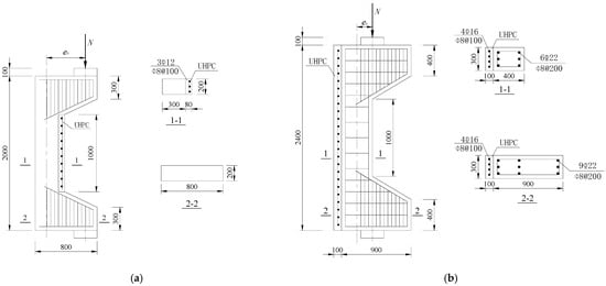
Figure 2.
Section size and steel-bar arrangement (units: mm): (a) inner-side reinforced NC column; (b) outer-side reinforced RC column.

Table 1.
Specifications of 12 schemes.
3.2. Finite Element Model
ABAQUS 2022—a finite element analysis platform renowned for its robust capabilities in nonlinear analysis, multi-material modeling, and comprehensive field output visualization—was employed to enable accurate simulation of the structural behavior under investigation. In ABAQUS, the solid element (C3D8R) was used to simulate the concrete and UHPC reinforcement layers, and the truss element (T3D2) was used to simulate the reinforcement. The steel reinforcement was added to the concrete or UHPC strengthening layer by “embed”, and the interface between the concrete and UHPC was set as a “tie” connection. In order to reduce the local stresses near the loading surface during loading, rigid pads with a thickness of 20 mm were set at each end. The finite element model is shown in Figure 3.
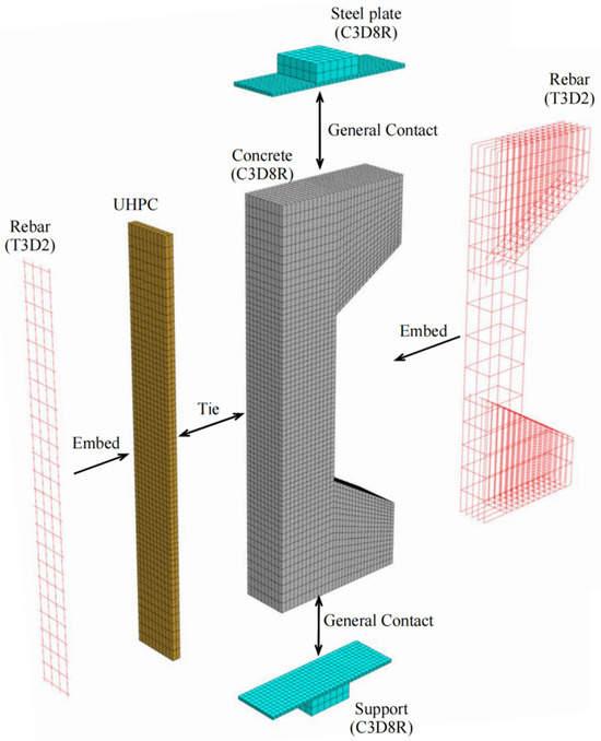
Figure 3.
Finite element model of the RCU-OUT-200 column.
The members are first loaded and then reinforced on one side. Therefore, in the simulation, two analysis steps are set up to control the activation and deactivation of elements, simulating the participation of the UHPC reinforcement layer under secondary loading. In the first step, the “model change” function is used to “kill” the reinforcing layer elements, and an initial displacement load is applied to the eccentrically loaded column. In the second step, the “model change” function activates the reinforcing layer elements, and a “tie constraint” is utilized to integrate them with the original column. The vertical displacement is then increased until the member fails.
3.3. Material Properties
To investigate the failure characteristics of eccentrically loaded specimens before and after reinforcement, both UHPC and concrete adopt the Concrete Damaged Plasticity (CDP) model, which can microscopically simulate the formation and development of tensile cracks and the materials’ compressive plasticity. For steel bars, the double-line elastic-plastic model is selected. According to the related specifications, material parameters for each material in the numerical analysis are shown in Table 2 [35,36,37,38,39].

Table 2.
Material parameters used in Abaqus.
3.4. Failure Modes
Before reinforcement, the eccentrically loaded column bears the load alone during the first phase, generating initial stress and strain. After reinforcement, UHPC and the concrete column deform together under the action of the second-phase load. Through numerical simulation, the failure patterns of NC and RC columns under different working conditions are illustrated through the software functions “DAMAGET” and “DAMAGEC,” as shown in Table 3, Table 4, Table 5 and Table 6.

Table 3.
Failure patterns of eccentrically loaded NC columns (e0 = 180 mm) before and after reinforcement.

Table 4.
Failure patterns of eccentrically loaded NC columns (e0 = 500 mm) before and after reinforcement.

Table 5.
Failure patterns of eccentrically loaded RC columns (e0 = 200 mm) before and after reinforcement.

Table 6.
Failure patterns of eccentrically loaded RC columns (e0 = 550 mm) before and after reinforcement.
The ten column specimens exhibit distinct failure modes depending on their reinforcement configurations and loading positions. In terms of crack propagation patterns, the ductility and strain-hardening properties of UHPC enable the strengthening layer to participate in load-bearing and provide primary resistance after activation. The bridging effect of steel fibers in UHPC effectively suppresses the generation and development of cracks so that outer-side reinforcement results in more densely distributed cracks in the concrete with slower through-depth advancement, exhibiting significant ductile failure characteristics. In contrast, inner-side reinforced specimens exhibit deeper crack penetration through the concrete section, particularly in plain concrete portions which maintain characteristic brittle failure modes. Regarding the damage of concrete, the UHPC-reinforced columns under small eccentricity conditions exhibit combined crushing–splitting failure with expanded damage zones, while the UHPC-reinforced columns under large eccentricity conditions show significantly enlarged crushing areas due to UHPC’s tensile stress redistribution. For inner-side reinforced columns under large eccentricity conditions, the Ultra-High Performance Concrete (UHPC) mainly bears the compressive stress, and the original columns crack under tension but do not experience crushing. Additionally, owing to the initial strain in the original column, the strain and stress in the UHPC always lag behind, and the failure occurs relatively late.
These findings imply that for tunnel structures, the crack distribution characteristics of the original lining undergo significant changes after reinforcement. Specifically, the inner tensile zone features densely packed cracks with slow propagation, whereas the inner compressive zone displays significantly deeper cracks. Furthermore, the degree of damage varies at different locations along the tunnel.
The ten column specimens exhibit distinct failure modes depending on their reinforcement configurations and loading positions. In terms of crack propagation patterns, the ductility and strain-hardening properties of UHPC enable the strengthening layer to participate in load-bearing and provide primary resistance after activation. The bridging effect of steel fibers in UHPC effectively suppresses the generation and development of cracks so that outer-side reinforcement results in more densely distributed cracks in the concrete with slower through-depth advancement, exhibiting significant ductile failure characteristics. In contrast, inner-side reinforced specimens exhibit deeper crack penetration through the concrete section, particularly in plain concrete portions which maintain characteristic brittle failure modes. Regarding the damage to concrete, the UHPC-reinforced columns under small eccentricity conditions exhibit combined crushing–splitting failure with expanded damage zones, while the UHPC-reinforced columns under large eccentricity conditions show significantly enlarged crushing areas due to UHPC’s tensile stress redistribution. For inner-side reinforced columns under large eccentricity conditions, the Ultra-High Performance Concrete (UHPC) mainly bears the compressive stress, and the original columns crack under tension but do not experience crushing. Additionally, owing to the initial strain in the original column, the strain and stress in the UHPC always lag behind, and the failure occurs relatively late.
These findings indicate that for tunnel structures, the crack distribution characteristics of the original lining undergo significant changes after reinforcement. Specifically, the inner tensile zone features densely packed cracks with slow propagation, whereas the inner compressive zone displays significantly deeper cracks. Furthermore, the degree of damage varies at different locations along the tunnel.
3.5. Load-Displacement Curves
Load-displacement curves are shown in Figure 4. Combined with the failure modes of columns above, the loading process of eccentrically loaded columns can be divided into three stages: ① Elastic stage: At the beginning of loading, all materials are in an elastic state, and there is a linear relationship between the loads and lateral deflections. The columns exhibit slight displacement and high initial stiffness. ② Elastic-plastic stage: As the load continues to increase, the number and growth rate of cracks in eccentrically loaded columns multiply significantly, and the compressive plastic zone expands. As some materials yield and enter the plastic range, the lateral displacements of columns increase significantly. The slopes of the curves decrease with increasing loads, indicating a substantial reduction in stiffness. ③ Failure stage: When loaded to the ultimate strain of concrete or steel bars, the eccentrically loaded columns reach their ultimate bearing capacity and no longer bear additional loads. Afterwards, the load-lateral displacement curves decrease.
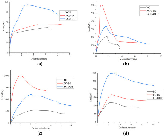
Figure 4.
Load-displacement curves of eccentrically loaded columns: (a) NC columns with an eccentricity of 180 mm; (b) NC columns with an eccentricity of 500 mm; (c) RC columns with an eccentricity of 200 mm; (d) RC columns with an eccentricity of 550 mm.
The peak loads in the load-lateral displacement curves are regarded as the ultimate load-carrying capacity. For NC columns, when the eccentricity is 500 mm, the ultimate bearing capacity of the unreinforced column is 51.3 MPa, while that of the externally reinforced column is 94.3 MPa, and that of the internally reinforced column is 56.8 MPa. The bearing capacities of the reinforced columns are increased by 84.0% and 10.7%, respectively. When the eccentricity is 180 mm, the ultimate bearing capacity of the unreinforced column is 211.7 MPa, while that of the externally reinforced column is 338.9 MPa, and that of the internally reinforced column is 602.5 MPa. The bearing capacities of the reinforced columns are increased by 60.1% and 184.6%, respectively. For RC columns, at an eccentricity of 550 mm, the ultimate bearing capacity of the unreinforced column is 120.6 MPa, while the outer-side reinforced column reaches 299.2 MPa and the inner-side reinforced column achieves 166.8 MPa, corresponding to enhancements of 148.1% and 38.3%, respectively. When the eccentricity is 200 mm, the ultimate bearing capacity of the unreinforced column is 541.1 MPa, whereas the outer-side reinforced column attains 1209.3 MPa and the internally reinforced column achieves 2091.4 MPa, representing increases of 123.4% and 286.5%, respectively.
The load-displacement curves of all specimens exhibit identical trends before reinforcement. However, during the later loading phases, the slope of the load-deflection curve of UHPC-reinforced columns is significantly steeper than that of the controlled columns. Moreover, the stiffness of the reinforced columns does not decrease significantly within a large range of load increments. Moreover, the horizontal displacements at the mid-height of the columns corresponding to the peak loads are all smaller in the reinforced columns than in the non-reinforced ones. This is because the reinforced UHPC layer effectively inhibits further crack propagation in the eccentric columns. On the other hand, the composite section formed by the UHPC reinforcement layer and the original column increases the flexural inertia of the section, thereby restricting the deformation of the columns. Furthermore, for NC columns with an eccentricity of 180 mm and RC columns with an eccentricity of 200 mm, the slope of the ascending branch for internally reinforced columns is greater than that for externally reinforced columns, suggesting that internal reinforcement provides a more pronounced enhancement in stiffness under small eccentricities. Conversely, for NC columns with an eccentricity of 500 mm and RC columns with an eccentricity of 550 mm, the slopes of the ascending branch for outer-side reinforced columns exceed those of inner-side reinforced columns, demonstrating that outer-side reinforcement is more effective in improving stiffness under larger eccentricities.
The descending branches of load-displacement curves vary across scenarios. For NC columns with 500 mm eccentricity, outer-side reinforced columns show a rapid peak load ascent and prolonged descent, while inner-side reinforced columns reach peak load smoothly and descend moderately. Unreinforced columns decline rapidly after peak load. For NC columns with 180 mm eccentricity, inner-side reinforced columns exhibit a sharp decline followed by a prolonged tensile phase, outer-side reinforced columns show a gradual descent, and unreinforced columns have a steep and short descent. For RC columns with 200 mm eccentricity, inner-side reinforced columns have a short descending branch, while unreinforced and outer-side columns show moderate, gradual descents. For RC columns with 550 mm eccentricity, all columns descend slowly after peak load, with outer-side reinforced columns having the longest descent, followed by inner-side reinforced and unreinforced columns.
The above analysis indicates that the UHPC reinforcement layer significantly enhances the ultimate bearing capacity and stiffness of the columns while reducing lateral displacement, with the strengthening effect is strongly dependent on eccentricity and reinforcement location. For small eccentricities, internal reinforcement provides a more pronounced improvement in stiffness and bearing capacity, whereas external reinforcement is more effective under large eccentricities. The distinct post-peak behaviors in the load-displacement curves further indicate that external reinforcement provides superior ductility under large eccentric loading. In tunnel applications, since UHPC’s contribution varies across secondary lining sections with different eccentricities, its overall effect on the tunnel’s bearing capacity and stiffness is non-uniform [36].
4. Calculation of Load-Bearing Capacity
4.1. Assumptions
- The cross-section of a structure remains approximately planar after experiencing force-induced deformation, with strain varying linearly along the height of the section.
- The steel bars remain bonded to the concrete or UHPC without relative slippage [40].
- The UHPC reinforcing layer has no relative displacement with the concrete column, and they always remain closely adhered.
- When considering the effects of secondary loading, the lagging strain in the UHPC should be determined based on the initial state of the column before reinforcement.
- To facilitate the calculation, the tensile stress of concrete is neglected, and the stress–strain relationship of concrete in the compression zone is simplified, as shown in Figure 5 and Equation (1) [36].where is the compressive strain of concrete. is the compressive stress of concrete corresponding to . Ec is the elastic modulus of concrete. is the uniaxial compressive strength of concrete. is the compressive strain of concrete corresponding to . is the ultimate strain of concrete under compression.
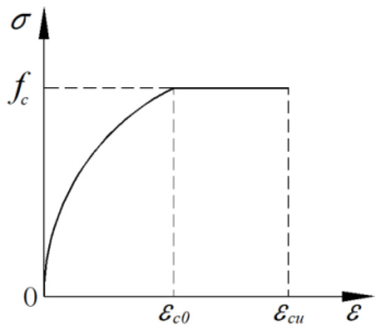 Figure 5. Stress–strain relationship of concrete under compression.
 - In the ultimate limit state, an equivalent coefficient αc is introduced to take the stress distribution of concrete in the compression zone as a rectangular distribution while ignoring the stress in the tension zone of the concrete.
- The mechanical behavior of UHPC before reaching its peak strength is modeled as a linear elastic stress–strain relationship. After UHPC attains its ultimate tensile stress, the embedded steel fibers can still provide residual tensile resistance. For safety considerations, the post-peak descending branches are neglected in this analysis. The stress–strain relationship of UHPC is illustrated in Figure 6 and described by Equations (2) and (3) [38,41].
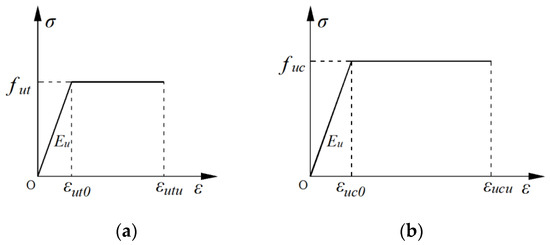 Figure 6. Stress–strain relationship of UHPC: (a) under compression; (b) under tension.
UHPC under tension:
UHPC under compression:
where εut is the tensile strain of UHPC. σut is the tensile stress of UHPC corresponding to εut. is the peak tensile strength of UHPC. is the tensile strain of UHPC corresponding to . is the ultimate strain of UHPC under tension. εuc is the tensile strain of UHPC. σuc is the tensile stress of UHPC corresponding to εut. is the peak compressive strength of UHPC. is the compressive strain of UHPC corresponding to . is the standard value of the cube compressive strength of UHPC. is the ultimate strain of UHPC under compression.
4.2. Failure Modes
Unlike conventional concrete, UHPC exhibits high tensile strength, strain-hardening behavior, and good ductility due to the effect of fiber-bridging. Before reaching its ultimate tensile strain, UHPC can share the load with the reinforcing steel. Moreover, the eccentrically loaded member fails once any component material (steel, concrete, or UHPC) reaches its ultimate strain limit. Consequently, UHPC-reinforced eccentrically loaded columns may exhibit the failure modes listed in Table 7 and Table 8.

Table 7.
Failure modes of UHPC-reinforced NC columns.

Table 8.
Failure modes of UHPC-reinforced RC columns.
4.3. Theoretical Derivation
To align with the practical application of tunnel reinforcement, the corresponding bearing capacity calculation formula is theoretically derived for UHPC unilaterally reinforced NC and RC eccentrically loaded members based on the calculation assumptions. During the derivation, the stress–strain lagging in the UHPC reinforcing layer under the secondary loading should be considered. In order to avoid the resultant point of the compression zone acting within the protective layer of the reinforced concrete or UHPC, the height of the compression zone in the concrete or UHPC should meet x ≥ 2as′. If part of the concrete exceeds the ultimate tensile strain, the concrete in that area fails and no longer provides compressive stress.
4.3.1. Bearing Capacity of the NCU Column
- Outer-side reinforcement
The reinforcement layer is in a tension or compression state depending on the magnitude of the eccentricity. The stress–strain distribution in the cross-section of the reinforced NC eccentrically loaded member under an ultimate state is shown in Figure 7.
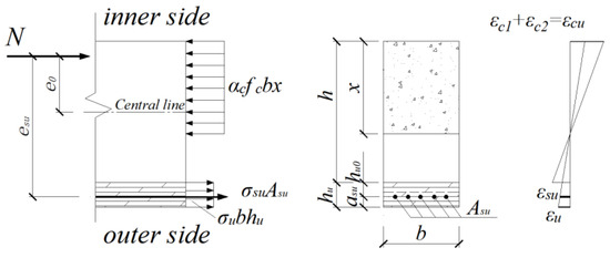
Figure 7.
Stress–strain distribution in the cross-section of the NCU-OUT column.
Based on the equilibrium conditions of forces and moments in the cross-section, , the equations can be obtained as follows:
where N is the axial force, and αc is the equivalent coefficient of the rectangular stress diagram of the concrete in the compression zone. b is the section width of the concrete column. h is the height of the concrete column section. x is the height of the concrete compression zone. is the stress of steel bars in the UHPC. is the area of steel bars in the UHPC. is the average stress of UHPC. hu is the thickness of the UHPC reinforcement layer. is the protective layer thickness of steel bars in the UHPC. e0 is the distance from the point of application of axial force N to the section’s center of gravity. esu is the distance from the point of application of axial force N to the center of the steel bars in the UHPC.
At the point of failure, the concrete on the compression side reaches its ultimate compressive strain εcu. According to the plane section assumption, the strain relationships among the various materials are as follows:
where is the strain at the outer edge of the UHPC reinforcement layer. is the initial compressive strain at the edge of the concrete before reinforcement. is the secondary compressive strain at the edge of the concrete after reinforcement. is the strain of steel bars in the UHPC.
According to the constitutive relationships of each material, the ultimate bearing capacity Nu at different eccentricities can be obtained from Equations (4)–(6).
- 2.
- Inner-side reinforcement
The reinforcement layer is always in a compressive state. The stress–strain distribution in the cross-section of the reinforced NC eccentrically loaded column under ultimate load is shown in Figure 8.
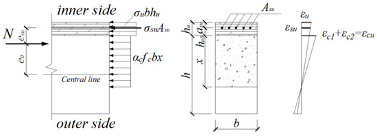
Figure 8.
Stress–strain distribution in the cross-section of the NCU-IN column.
Based on the equilibrium conditions of longitudinal forces and moments in the cross-section, the following two basic equations can be obtained.
According to the plane section assumption, the strain relationships among the various materials are as follows:
According to the constitutive relationship of each material, the ultimate bearing capacity Nu at different eccentricities can be obtained from Equations (7)–(9).
4.3.2. Bearing Capacity of the RCU Column
- Outer-side reinforcement
The reinforcement layer is in a tension or compression state under different eccentricities. The stress–strain distribution in the cross-section of the reinforced RC eccentrically loaded member under ultimate load is shown in Figure 9.
where is the yield strength of steel bars in the compression zone. are the area of steel bars in the tension zone (or on the side with lower pressure) and compression zone, respectively. are the protective layer thickness of steel bars in the tension zone (or on the side with lower pressure) and compression zone, respectively. es is the distance from the point of application of axial force N to the center of the steel bars in the tension zone (or on the side with lower pressure).
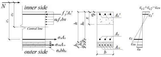
Figure 9.
Stress–strain distribution in the cross-section of the RCU-OUT column.
At the point of failure, the concrete on the compression side reaches its ultimate compressive strain . According to the plane section assumption, the strain relationships among the various materials are as follows:
where , are the strains of steel bars in the tension zone (or on the side with lower pressure) and compression zone, respectively.
According to the constitutive relationships of each material, the ultimate bearing capacity Nu at different eccentricities can be obtained from Equations (10)–(13).
- 2.
- Inner-side reinforcement
The reinforcement layer is always in a compressive state. The stress–strain distribution in the cross-section of the reinforced RC column under ultimate load is shown in Figure 10.

Figure 10.
Stress–strain distribution in the cross-section of the RCU-IN column.
Based on the equilibrium conditions of longitudinal forces and moments in the cross-section, the following two basic equations can be obtained.
According to the plane section assumption, the strain relationships among the various materials are as follows:
According to the constitutive relationships of each material, the ultimate bearing capacity Nu at different eccentricities can be obtained from Equations (14)–(17).
4.4. Formulas Verification
By substituting the specimen parameters from Section 4.3 into the above equations, the bearing capacity values for UHPC-reinforced columns are obtained. Although these values are generally lower than the numerical results, with deviations less than 10% as indicated in Table 9, the proposed equations demonstrate high precision and safety margins. They show good agreement and can provide a valuable reference for the design and construction of UHPC-reinforced tunnels.

Table 9.
Comparison of numerical results and theoretical results.
5. Parametric Analysis
To better guide the selection of parameters and facilitate the rational and cost-efficient application of UHPC, the impacts of initial strain, UHPC strength, reinforcement layer thickness, and reinforcement ratio on the reinforcement effectiveness of eccentrically loaded columns are analyzed. Based on the parameters in Section 4, the M-N curves at an initial strain of 0.001 under different conditions are obtained through calculation formulas to investigate the changes in structural bearing capacity.
5.1. Reinforcement Layer Thickness
To evaluate the impact of UHPC thickness on reinforcement performance, hu was set to 30 mm, 45 mm, and 60 mm for NC columns and to 50 mm, 80 mm, and 110 mm for RC columns, with all other parameters held constant. The bearing capacities of eccentrically loaded columns reinforced with UHPC of different thicknesses on both the outer and inner sides are shown in Figure 11.
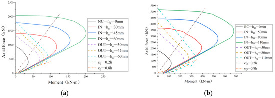
Figure 11.
M-N curves of the columns reinforced with UHPC of different thicknesses: (a) NC columns; (b) RC columns.
Under small eccentricity (e0 = 0.2 h), for NC columns with UHPC thicknesses of 30 mm, 45 mm, and 60 mm, inner-side reinforcement increases the load-bearing capacity by 2.5, 2.9, and 3.4 times, respectively. For RC columns with UHPC thicknesses of 50 mm, 80 mm, and 110 mm, inner-side reinforcement enhances the load-bearing capacity by 2.1, 3.3, and 4.4 times, respectively. In contrast, outer-side reinforcement shows weaker improvement under low eccentricity, with load-bearing capacity increases of 1.5~2.0 times for NC columns and 2.7~3.5 times for RC columns. This is because the load application point is closer to the centroid of the column section, and the inner-side reinforcement can make better use of the compressive strength of Ultra-High Performance Concrete (UHPC).
Under large eccentricity (e0 = 0.2 h), for NC columns with UHPC thicknesses of 30 mm, 45 mm, and 60 mm, outer-side reinforcement increases the load-bearing capacity by 2.2, 2.8, and 4.8 times, respectively. For RC columns with UHPC thicknesses of 50 mm, 80 mm, and 110 mm, outer-side reinforcement enhances the load-bearing capacity by 2.6, 3.8, and 5.8 times, respectively. In contrast, inner-side reinforcement shows weaker improvement under high eccentricity, with load-bearing capacity increases of 1.6–2.4 times for NC columns and 1.8–3.4 times for RC columns. This phenomenon is attributed to the fact that when the load application point is at a greater distance from the centroid of the column, the outer-side reinforcement layer can effectively counteract the tensile stresses, thereby significantly enhancing the load-bearing capacity.
Additionally, noticeable discontinuities are observed in the M-N curves. This is because when the eccentricity exceeds a certain threshold, the UHPC in outer-side reinforced columns cracks and exits the working state due to excessive tensile strain, leaving the internal reinforcement to bear the load alone. This phenomenon is particularly evident under high eccentricity, reflecting the failure process of UHPC after reaching its tensile limit.
In summary, the load-bearing capacity of both NC and RC columns significantly improves with the increase in UHPC thickness. Inner-side reinforcement is more effective under low eccentricity, primarily utilizing the compressive strength of UHPC, while outer-side reinforcement is more effective under high eccentricity, directly resisting tensile stresses. In this way, for tunnel reinforcement projects, the load-bearing capacity improvement magnitude varies across different tunnel sections due to the combined influence of eccentricity and reinforcement positioning. During the reinforcement design, it is essential to perform in-depth checks on these critical locations to ensure the safety of tunnels.
5.2. Reinforcement Ratio
To explore the effect of reinforcement ratio of UHPC reinforcement layer on the bearing capacity of eccentrically loaded columns, reinforcement layers with different steel bar diameters were selected to reinforce eccentrically loaded columns. For NC columns, a comparative study was conducted using steel bars with diameters of 6 mm, 8 mm, and 10 mm, which correspond to reinforcement ratios of 7.54%, 13.40%, and 20.94%, respectively. Similarly, for RC columns, steel bars with diameters of 6 mm, 10 mm, and 14 mm were used, corresponding to reinforcement ratios of 3.02%, 8.38%, and 16.42%, respectively.
Figure 12 shows the M-N curves of the eccentrically loaded columns reinforced with different reinforcement ratios. When large eccentrically loaded columns are reinforced with UHPC on the outer side, the steel bars play a major role after the reinforcement layer cracks, and the reinforcement ratio has a greater impact on the bearing capacity compared to other working conditions. However, the limited thickness of the reinforcement layer constrains the application of large-diameter steel bars, resulting in merely a 6–8% enhancement in the moment of inertia even with an increased reinforcement ratio. In other cases, the resistance produced by steel bars is of a small proportion and contributes little to the improvement of the bearing capacity.
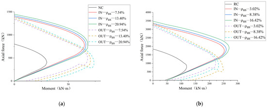
Figure 12.
M-N curves of columns reinforced with UHPC of different reinforcement ratio: (a) NC column; (b) RC column.
In tunnel reinforcement, the UHPC arch is generally reinforced according to structural requirements. If some areas experience significant inward deformation, causing severe tensile stress on the UHPC arch, FRP bars or steel plates can be added [19].
5.3. UHPC Strength
UHPC with strength grades of U120, U130, and U140 was chosen for the analysis of bearing capacities of reinforced columns. The corresponding compressive strengths are 84 MPa, 96 MPa, and 112 MPa, respectively, and the tensile strengths are 6 MPa, 7 MPa, and 8 MPa.
Figure 13 shows that the bearing capacity of eccentrically loaded columns reinforced with different-strength UHPC is significantly greater than that of unreinforced columns, but the rate of increase varies. When the eccentricity exceeds a certain threshold, curves basically coincide due to the inability of UHPC to play its role. When the eccentricity is below a specific threshold, the bearing capacity of U130 is approximately 10% higher than that of U120. For NC columns, the load-displacement curves of U130 and U140 nearly coincide, whereas for RC columns, the difference between the two curves diminishes as eccentricity decreases. This shows that UHPC of U140 fails to exhibit its high-strength material properties and cannot further significantly enhance the bearing capacity. To avoid material waste, UHPC of an appropriate grade should be selected according to the specific engineering application.
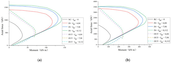
Figure 13.
M-N curves of columns reinforced with UHPC of different strength grades: (a) NC column; (b) RC column.
5.4. Initial Strain
Figure 14 shows the M-N curves of UHPC-reinforced eccentrically loaded columns under different degrees of predamage, with initial compressive strains of the concrete at εc1 = 0.001, εc1 = 0.002, and εc1 = 0.003. Through comparison, a higher initial strain results in a significantly lower improvement in bearing capacity. At an initial strain of εc1 = 0.003, the load-bearing capacities of the reinforced columns are only increased by approximately 10%. This is because the larger the deformation of the original column, the smaller the collaborative strain of the UHPC reinforcement layer before the reinforced column reaches the limit state, causing the reinforcement layer to function ineffectively and be underutilized. Consequently, for tunnels with severe damage, the UHPC arch is not an optimal choice.
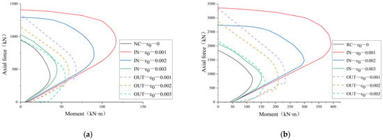
Figure 14.
M-N curves of columns reinforced with UHPC under different initial strains: (a) NC column; (b) RC column.
6. Discussion
Based on the theoretical derivation and numerical simulation results of this study, the enhancement mechanisms of ultra-high performance concrete (UHPC) in tunnel lining reinforcement can be elaborated at three interconnected levels, namely material performance, structural synergy, and long-term performance.
At the material performance level, UHPC, characterized by its ultra-high strength, high elastic modulus, and excellent interface bonding performance, is capable of directly bearing the loads transmitted by the structure, thereby reducing the stress burden on the original tunnel lining. Meanwhile, its favorable deformation compatibility contributes to inhibiting the initiation and propagation of lining cracks, which is crucial for maintaining structural integrity under service conditions.
At the structural synergy level, the UHPC reinforcement layer and the original tunnel lining form a “composite force-bearing system” through effective interface bonding, which fundamentally alters the force transmission path of the original structure. By virtue of its own stiffness, the UHPC layer participates in sharing part of the bending moment and shear force, leading to a more uniform force distribution of the overall structure and effectively avoiding local stress concentration that may induce premature failure.
At the long-term performance level, the high durability of UHPC, including its superior impermeability and carbonation resistance, provides an effective protective barrier for the original lining and internal steel bars, preventing them from corrosion-induced deterioration. This protective effect helps delay the structural degradation rate, thereby indirectly improving the long-term bearing capacity and extending the service life of the tunnel structure.
It should be emphasized that the aforementioned enhancement mechanisms are summarized based on the theoretical and numerical analysis results of this study. To further validate their reliability and applicability in practical engineering scenarios, subsequent experimental investigations will be conducted, which is expected to provide more direct evidence for the rationality of UHPC application in tunnel lining reinforcement.
7. Conclusions
This paper illustrates the reinforcement mechanism of the laminated UHPC arch based on the stress characteristics of tunnels. Through numerical simulation and theoretical derivation, it explores the potential failure modes, mechanical behaviors, and bearing capacity of RC and NC eccentrically loaded columns reinforced unilaterally with UHPC under different reinforcement positions and eccentricities. The following conclusions can be drawn.
- (1)
- The study found that UHPC reinforcement significantly enhanced the ultimate bearing capacity of both normal concrete (NC) and reinforced concrete (RC) columns. The improvements ranged from 84% to 184.6% for NC columns and 38.3% to 286.5% for RC columns compared to unreinforced specimens. This enhancement is attributed to the superior mechanical properties of UHPC, which effectively redistributes stress and delays crack propagation.
- (2)
- UHPC-reinforced specimens exhibited enhanced stiffness and superior ductility, maintaining deformation capacity at higher load levels. This is due to the effective stress redistribution provided by the reinforcement system, which allows the structure to better resist deformation and maintain structural integrity under load.
- (3)
- Theoretical formulas for the bearing capacity of UHPC-reinforced eccentric columns under secondary loading were derived using the plane section assumption and stress diagram equivalence method. These formulas were validated through numerical simulations, with deviations maintained within 10%. This consistency confirms the reliability of the theoretical models and their applicability for engineering design.
- (4)
- Secondary loading significantly influences the ultimate load-bearing capacity of UHPC-reinforced columns. As initial strain increases, the reinforcement layer faces greater challenges in providing resistance through subsequent deformation. Excessive initial strain reduces the bearing capacity improvement and compromises reinforcement effectiveness. This highlights the importance of controlling initial strain to maximize reinforcement benefits.
- (5)
- When eccentricity exceeds a certain threshold, UHPC may crack or fail to reach its ultimate strength, diminishing its reinforcement effect. Conversely, for small eccentricities (less than 0.5 h), UHPC exhibits significant reinforcement effectiveness, especially for internally reinforced columns, which show much higher ultimate bearing capacity than externally reinforced ones. This suggests that internal reinforcement is more effective for small eccentricities.
- (6)
- The bearing capacity of eccentrically loaded columns increases with the thickness, strength, and reinforcement ratio of the UHPC layer. Specifically, increasing the thickness of the UHPC layer significantly enhances bearing capacity. While higher UHPC strength also improves capacity, excessively high strength may lead to underutilization and material waste. A moderate reinforcement ratio is recommended for practical applications, with additional FRP bars or thin steel plates suggested for localized reinforcement when greater resistance is needed.
- (7)
- Tunnel linings typically experience compression and bending with small eccentricities (less than 0.5 h). The study demonstrates that a thin UHPC arch reinforcement can significantly enhance the load-bearing capacity of lining structures and effectively control tunnel deformation. This makes UHPC a promising material for tunnel reinforcement, offering both theoretical and practical validation for its use in engineering applications.
Author Contributions
Conceptualization, L.L.; theoretical analysis, L.L.; software, H.L. and H.H.; data analysis, H.L.; validation, L.L.; writing—original draft preparation, L.L.; writing—review and editing, H.H. and G.L.; visualization, H.L. and T.C.; supervision, L.L. All authors have read and agreed to the published version of the manuscript.
Funding
This study was funded by the Special Project on Key Areas for General Universities in Guangdong Province (New Generation of Information Technology) (No. 2021ZDZX1116); 2023 Guangzhou Higher Education Teaching Quality and Teaching Reform Project-Rail Transit Intelligent Construction and Safety Operation and Maintenance Industry Education Integration Training Base (No. 2023CJRHJD004); Basic and Applied Basic Research Projects of Guangzhou Basic Research Program (No. 2022-1175).
Data Availability Statement
The original contributions presented in this study are included in the article. Further inquiries can be directed to the corresponding author.
Conflicts of Interest
The authors declare no conflicts of interest. Author Gang Lei was employed by the company Beijing Urban Construction Design & Development Group Co., Ltd. The authors declare that this study received funding from Basic and Applied Basic Research Projects of Guangzhou Basic Research Program (No. 2022-1175). The funder was not involved in the study design, the collection, analysis, and interpretation of data, the writing of this article, or the decision to submit it for publication.
References
- Ye, F.; Qin, N.; Liang, X.; Ouyang, A.; Qin, Z.; Su, E. Analyses of the defects in highway tunnels in China. Tunn. Undergr. Space Technol. 2021, 107, 103658. [Google Scholar] [CrossRef]
- Xu, G.; Gutierrez, M. Study on the damage evolution in secondary tunnel lining under the combined actions of corrosion degradation of preliminary support and creep deformation of surrounding rock. Transp. Geotech. 2021, 27, 100501. [Google Scholar] [CrossRef]
- Ai, Q.; Yuan, Y.; Shen, S.L.; Wang, H.; Huang, X. Investigation on inspection scheduling for the maintenance of tunnel with different degradation modes. Tunn. Undergr. Space Technol. 2020, 106, 103589. [Google Scholar] [CrossRef]
- Jiang, Y.; Wang, L.; Zhang, B.; Dai, X.; Ye, J.; Sun, B.; Zhao, Y. Tunnel lining detection and retrofitting. Autom. Constr. 2023, 152, 104881. [Google Scholar] [CrossRef]
- Miliziano, S.; de Lillis, A.; Santarelli, S. Maintenance and refurbishment of existing tunnels. In Handbook on Tunnels and Underground Works; CRC Press: Boca Raton, FL, USA, 2022; pp. 333–350. [Google Scholar]
- Sharma, R.; Jang, J.G.; Bansal, P.P. A comprehensive review on effects of mineral admixtures and fibers on engineering properties of ultra-high-performance concrete. J. Build. Eng. 2022, 45, 103314. [Google Scholar] [CrossRef]
- Sohail, M.G.; Wang, B.; Jain, A.; Kahraman, R.; Ozerkan, N.G.; Gencturk, B.; Belarbi, A. Advancements in concrete mix designs: High-performance and ultrahigh-performance concretes from 1970 to 2016. J. Mater. Civ. Eng. 2018, 30, 04017310. [Google Scholar] [CrossRef]
- Akhnoukh, A.K.; Buckhalter, C. Ultra-high-performance concrete: Constituents, mechanical properties, applications and current challenges. Case Stud. Constr. Mater. 2021, 15, e00559. [Google Scholar] [CrossRef]
- Shafieifar, M.; Farzad, M.; Azizinamini, A. Experimental and numerical study on mechanical properties of Ultra High Performance Concrete (UHPC). Constr. Build. Mater. 2017, 156, 402–411. [Google Scholar] [CrossRef]
- Azmee, N.M.; Shafiq, N. Ultra-high performance concrete: From fundamental to applications. Case Stud. Constr. Mater. 2018, 9, e00197. [Google Scholar] [CrossRef]
- Prem, P.R.; Bharatkumar, B.H.; Iyer, N.R. Mechanical properties of ultra high performance concrete. World Acad. Sci. Eng. Technol. 2012, 68, 1969–1978. [Google Scholar]
- Tayeh, B.A.; Abu Bakar, B.H.; Megat Johari, M.A. Characterization of the interfacial bond between old concrete substrate and ultra high performance fiber concrete repair composite. Mater. Struct. 2013, 46, 743–753. [Google Scholar] [CrossRef]
- Feng, S.; Xiao, H.; Ma, M.; Zhang, S. Experimental study on bonding behaviour of interface between UHPC and concrete substrate. Constr. Build. Mater. 2021, 311, 125360. [Google Scholar] [CrossRef]
- Semendary, A.A.; Svecova, D. Factors affecting bond between precast concrete and cast in place ultra high performance concrete (UHPC). Eng. Struct. 2020, 216, 110746. [Google Scholar] [CrossRef]
- Valikhani, A.; Jahromi, A.J.; Mantawy, I.M.; Azizinamini, A. Experimental evaluation of concrete-to-UHPC bond strength with correlation to surface roughness for repair application. Constr. Build. Mater. 2020, 238, 117753. [Google Scholar] [CrossRef]
- Park, J.S.; Kim, Y.J.; Cho, J.R.; Jeon, S.J. Early-age strength of ultra-high performance concrete in various curing conditions. Materials 2015, 8, 5537–5553. [Google Scholar] [CrossRef]
- He, Z.H.; Jiang, Y.Y.; Shi, J.Y.; Qin, J.; Liu, D.E.; Yalçınkaya, Ç.; He, Y.F. Effect of silica fume on the performance of high-early-strength UHPC prepared with magnesium ammonium phosphate cement. Case Stud. Constr. Mater. 2024, 20, e03351. [Google Scholar] [CrossRef]
- Keke, L.; Yong, L.; Liuliu, X.; Junjie, Z.; Kangning, L.; Dingqiang, F.; Rui, Y. Rheological characteristics of Ultra-High performance concrete (UHPC) incorporating bentonite. Constr. Build. Mater. 2022, 349, 128793. [Google Scholar] [CrossRef]
- Hung, C.C.; El-Tawil, S.; Chao, S.H. A review of developments and challenges for UHPC in structural engineering: Behavior, analysis, and design. J. Struct. Eng. 2021, 147, 03121001. [Google Scholar] [CrossRef]
- Xiao, J.L.; Yang, T.Y.; Nie, X.; Li, B.Y.; Fan, J.S.; Shu, B.A. Experimental and numerical investigation on mechanical performance of continuous steel-UHPC composite slabs. Eng. Struct. 2022, 270, 114804. [Google Scholar] [CrossRef]
- Tayeh, B.A.; Bakar, B.H. Ultra-High-Performance Concrete (UHPC)-Applications Worldwide: A State-of-the-Art Review. J. Eng. Res. Technol. 2023, 10. [Google Scholar]
- Menétrey, P. UHPFRC cladding for the Qatar National Museum. In Proceedings of the International Symposium on Ultra-High Performance Fiber-Reinforced Concrete, Marseille, France, 21–23 October 2013; pp. 1–3. [Google Scholar]
- Abdal, S.; Mansour, W.; Agwa, I.; Nasr, M.; Abadel, A.; Onuralp Özkılıç, Y.; Akeed, M.H. Application of ultra-high-performance concrete in bridge engineering: Current status, limitations, challenges, and future prospects. Buildings 2023, 13, 185. [Google Scholar] [CrossRef]
- Mathern, A.; von der Haar, C.; Marx, S. Concrete support structures for offshore wind turbines: Current status, challenges, and future trends. Energies 2021, 14, 1995. [Google Scholar] [CrossRef]
- Tan, L.B.; Hafezolghorani, M.; Mohamed, A.; Ghaedi, K.; Voo, T.L. Utilizing Ultra-High Performance Concrete Overlay for Road Pavement Repair and Strengthening Applications. Adv. Technol. Innov. 2023, 8, 290–302. [Google Scholar] [CrossRef]
- Zeng, J.J.; Hao, Z.H.; Sun, H.Q.; Zeng, W.B.; Fan, T.H.; Zhuge, Y. Durability assessment of ultra-high-performance concrete (UHPC) and FRP grid-reinforced UHPC plates under marine environments. Eng. Struct. 2025, 323, 119313. [Google Scholar] [CrossRef]
- Zeng, J.J.; Zeng, W.B.; Ye, Y.Y.; Liao, J.; Zhuge, Y.; Fan, T.H. Flexural behavior of FRP grid reinforced ultra-high-performance concrete composite plates with different types of fibers. Eng. Struct. 2022, 272, 115020. [Google Scholar] [CrossRef]
- Lu, Z.; Feng, Z.G.; Yao, D.; Li, X.; Jiao, X.; Zheng, K. Bonding performance between ultra-high performance concrete and asphalt pavement layer. Constr. Build. Mater. 2021, 312, 125375. [Google Scholar] [CrossRef]
- Abbas, S.; Nehdi, M.L. Mechanical behavior of ultrahigh-performance concrete tunnel lining segments. Materials 2021, 14, 2378. [Google Scholar] [CrossRef] [PubMed]
- Wang, Z.; Fei, J.; Ma, W.; Chen, X. Full-scale loading experiments on performance of UHPC joints for prefabricated mountain tunnel. Tunn. Undergr. Space Technol. 2023, 131, 104784. [Google Scholar] [CrossRef]
- Cheng, Q.; Li, Z.; Deng, S.; Jiang, H.; Tian, Y.; Geng, J. Full-scale experimental study on flexural performance of the new precast UHPC diaphragm slab in utility tunnels. Buildings 2023, 13, 1349. [Google Scholar] [CrossRef]
- Chen, R.P.; Fan, M.; Cheng, H.Z.; Wu, H.N.; Zhang, Y.; Ruan, S.Q.; Gao, B.Y. Experimental and analytical study on the mechanical response of shield tunnel segmental linings strengthened by a steel-UHPC composite. Tunn. Undergr. Space Technol. 2024, 150, 105824. [Google Scholar] [CrossRef]
- Gao, B.Y.; Chen, R.P.; Wu, H.N.; Chen, T.; Zhang, Y. Enhancement mechanism of UHPC secondary lining on the mechanical performance at joints of shield tunnels: Full-scale experiment and simulation. Tunn. Undergr. Space Technol. 2025, 157, 106282. [Google Scholar] [CrossRef]
- Luo, X.; Zhang, S.; Li, A.; Zhang, C.; Zhang, Y. Reinforcement effects on tensile behavior of ultra-high-performance concrete (UHPC) with low steel fiber volume fractions. Materials 2024, 17, 2418. [Google Scholar] [CrossRef] [PubMed]
- Zeng, J.J.; Guo, Y.C.; Liao, J.; Shi, S.W.; Bai, Y.L.; Zhang, L. Behavior of hybrid PET FRP confined concrete-filled high-strength steel tube columns under eccentric compression. Case Stud. Constr. Mater. 2022, 16, e00967. [Google Scholar] [CrossRef]
- GB50010; Code for Design of Concrete Structures. Ministry of Housing and Urban-Rural Development of the People’s Republic of China: Beijing, China; China Architecture and Building Press: Beijing, China, 2010.
- GB/T50010; Code for Design of Concrete Structures. Ministry of Housing and Urban-Rural Development of the People’s Republic of China: Beijing, China; China Architecture and Building Press: Beijing, China, 2010.
- T/CCES; Technical Specification for Ultra-High Performance Concrete Girder Bridge. China Civil Engineering Society: Beijing, China; Architecture and Building Press: Beijing, China, 2021.
- Lin, Z.Y. Performance Study of Partially Reinforced Prefabricated Concrete Columns with UHPC Shell. Master’s Thesis, Southeast University, Nanjing, China, 2022. [Google Scholar]
- Zhang, D.; Ma, X.; Shen, H.; Guo, S.; Liu, C. Analysis of Structural Parameters of Steel–NC–UHPC Composite Beams. Materials 2023, 16, 5586. [Google Scholar] [CrossRef]
- Zhu, Y.; Zhang, Y.; Hussein, H.H.; Chen, G. Flexural strengthening of reinforced concrete beams or slabs using ultra-high performance concrete (UHPC): A state of the art review. Eng. Struct. 2020, 205, 110035. [Google Scholar] [CrossRef]
Disclaimer/Publisher’s Note: The statements, opinions and data contained in all publications are solely those of the individual author(s) and contributor(s) and not of MDPI and/or the editor(s). MDPI and/or the editor(s) disclaim responsibility for any injury to people or property resulting from any ideas, methods, instructions or products referred to in the content. |
© 2025 by the authors. Licensee MDPI, Basel, Switzerland. This article is an open access article distributed under the terms and conditions of the Creative Commons Attribution (CC BY) license (https://creativecommons.org/licenses/by/4.0/).


