Article

A Large-Span Ring Deployable Perimeter Truss for the Mesh Reflector Deployable Antenna

1
Department of Mechanical Engineering, College of Engineering, Shantou University, Shantou 515063, China
2
Shantou Key Laboratory for Intelligent Equipment and Technology, Shantou 515063, China
3
School of Integrated Circuit, Shenzhen Polytechnic University, Shenzhen 518055, China
4
Key Laboratory of Electronic Equipment Structure, Design of Ministry of Education, Xidian University, Xi’an 710071, China
*
Authors to whom correspondence should be addressed.
Symmetry 2025, 17(9), 1388; https://doi.org/10.3390/sym17091388
Submission received: 11 July 2025 / Revised: 11 August 2025 / Accepted: 22 August 2025 / Published: 25 August 2025
(This article belongs to the Section Engineering and Materials)

Abstract

This paper presents a novel large-span ring deployable perimeter truss for the mesh reflector deployable antennas, which is made up of two parts including a single-mobility driving mechanism and a ring deployable metamorphic mechanism. The mechanism design employs polygon approximation, and each side is treated as a basic unit using a modular design approach. By reasonable assembly, a ring deployable metamorphic mechanism with a small folded state and a large deployed state can be formed. Here, multiple singular positions, the axis of its three revolute joints being parallel and coplanar, are used in the fully deployed state, which forms multiple dead-center positions and changes the constraint conditions. The metamorphic motion is thus achieved, and a stable self-locking state is established that greatly enhances the stability. The paper first introduces the mechanism design and evaluation method; the kinematic and dynamic analysis is then conducted, and the simulation validation is also performed. Moreover, a principle design for cable-net structural setting and connection is illustrated. Finally, with the design of a driving system and the fabrication of a physical prototype, the deployable experiments are carried out, and the results show that the perimeter truss can efficiently act as the mesh reflector deployable antennas.

1. Introduction

Space satellite antennas are widely used in many fields such as wireless communication [1,2]. Due to the long distance, the signal received by the satellite antennas is usually weak. Therefore, satellite antennas must possess high gain. Furthermore, to fulfill the demands for multi-functionality, these antennas are likely to have larger apertures. Consequently, traditional fixed surface antennas are unable to meet the requirements due to their bulky structure, high cost, and large volume [3,4]. In this case, the mesh reflector deployable antennas provide a good solution to this crisis, which has the advantages of a simple structure, a high storage ratio, lightweight, and good signal transmission stability. They are currently the ideal structural form for large-span deployable satellite antennas. The main components of the mesh reflector deployable antennas include a cable-net structure used for mesh and a large-span ring deployable perimeter truss. Here, the large-span ring deployable perimeter truss plays an important role as a supporting mechanism for its stable on-orbit operation [5,6], which has thus become a hot research topic, and researchers have proposed numerous design schemes that can be reviewed as follows.
Tserodze outlined two innovative design changes for symmetric radio telescopes that enhanced stiffness and stability by integrating two conical pantograph systems [7]. Qi created a series of large deployable mechanisms using plane-symmetric Bricard linkage, featuring a single degree of freedom, allowing them to unfold from a compact state to a rectangular plane [8,9,10]. Lu presented a large-scale deployable ring truss featuring a comprehensive rope-driven mechanism and an additional cable net system to create a complete space antenna [11]. Li created a deployable ring mechanism designed to support a large flexible cable net antenna reflector, consisting of several deployable modules and featuring a high deploy/fold ratio [12]. Knight optimized two types of trusses based on a mathematical technique of employing line geometry as defined by the mathematicians Plucker and Grassmann [13]. Xu discussed a mechanism with multiple mobility constraints designed for large mesh antennas, followed by the structural design, deployment control design, static analysis, and model testing [14,15]. Feng proposed an exhaustive search method for designing new deployable mechanisms of reflector antennas that are based on graph theory and a flow value method [16]. Han presented a scissors double-ring truss deployable mechanism to improve the structural stiffness of the ring truss deployable antenna mechanism [17,18,19,20]. Cao illustrated a new topological scheme and a new rectangular prism deployable linkage unit, and then the topological structure design and kinematic analysis of a novel double-ring truss deployable satellite antenna mechanism were conducted [21]. He proposed a general dynamic analysis methodology for cable-truss coupling to depict the time-varying resistance of the cable network and capture the cable-truss coupling behavior during the deployment process [22]. Yang studied a novel deployable antenna consisting of a double-ring deployable truss and a cable net reflector; the structural design and the geometric relationship are then formulated [23,24,25,26]. Gao introduced an innovative large-span two-fold deployable system primarily consisting of a multi-point driving mechanism and a circular deployable mechanism, which ingeniously altered the driving approach [27]. Yang addressed a three-layer cable-net structure approach to support the concave–convex-shaped mesh reflector [28,29]. Du conducted a dynamic analysis of the deployment for mesh reflector antennas driven with variable-length cables and considered cable net and truss flexibility [30]. Wu investigated the frequency characteristics of a beam–ring structure, which is proposed for the first time to model the circular truss antenna in the case of the antenna expanded and locked [31]. Xu proposed a 3UU-3URU deployable unit with two kinds of DOF, including folding movement and orientation adjustment to form a space deployable antenna [32]. Shi created a new type of cable-strut-tensioned antenna mechanism that was proposed and subjected to multi-objective optimization [33].
Based on the above review, the proposed solutions achieved the expected results to a certain extent for the mesh reflector deployable antennas, but several common issues need to be further considered. The first issue is the driving method. For most of the previously proposed design schemes, the ring deployable mechanism is always one-mobility, so any joint that can serve as a driving joint in theory and a prismatic joint is usually selected; such a method often achieves good results for small aperture antennas. For large aperture antennas, however, some joints gradually move away from the driving joint during the deployable process. Due to the interference of various physical factors, such as damping, the driving force continuously decays during the deployable process. The result is that the various parts of the ring deployable mechanism cannot be deployed synchronously, which is likely to cause the failure of the deployable process or even the failure of the space mission. The second issue is stability. With the continuous increase of antenna aperture, stability is an important indicator affecting their on-orbit operation. One existing solution is to use double-layer trusses instead of single-layer trusses, as mentioned in references [14,17]. Such a method can quickly improve stability, but the quality and complexity of the structure also rapidly increase. Theoretically, the design idea of the metamorphic mechanisms can be adopted for the stiffening process, where singular positions can be used to change the constraint condition of the ring deployable mechanism. Dai et al., as pioneers, have done a lot of studies in this field and achieved excellent results [34,35,36,37,38,39]. Gao fully studied previous achievements and successfully introduced the metamorphic mechanism into the design of aerospace mechanisms [40], which provides an effective design approach.
To overcome the above challenges, a novel large-span ring deployable perimeter truss is presented, consisting of a single-mobility driving mechanism and a ring deployable metamorphic mechanism, which regards the stiffening process of the ring deployable mechanism as an important issue and employs the metamorphic idea. Further, due to the use of the regular polygon approximation technique, the modular design method is adopted in the design for each side of the regular polygon, which effectively reduces the difficulty of design and improves the scalability of the ring deployable mechanism. Moreover, revolute joints and planar mechanisms are used in basic units to avoid the influence of complex motion joints, and single-mobility basic units are finally achieved through the coupling of multiple motion joints. In addition, by using a special connection method, the basic units are connected into a ring deployable mechanism with a small folded state and a large deployed state. When the ring deployable mechanism is fully deployed, each basic unit moves exactly to its singular position, while the constraints condition has changed and the axes of three revolute joints are parallel and coplanar. As a result, metamorphic motion occurs, and the entire ring deployable mechanism achieves the transformation from mechanism to rigid structure, which is also called metamorphic self-locking in this paper. Such a feature is very important for the stability of large or ultra-large aperture antennas. Mechanism design with motion analysis and evaluation methods is first introduced. Following this, the kinematic and dynamic modeling of the ring deployable mechanism is conducted to determine the performance index. On this basis, the cable-net structure is well-designed, and the connection method with the large-span ring deployable perimeter truss is studied. The prototype is produced, and deployable experiments are executed in the final, which fully proves the feasibility and reliability.
The rest of this paper is layout as follows: detailed mechanism design, motion analysis, and evaluation method of the deployable mechanism are first performed in Section 2; performance analysis, including the kinematics and dynamics, is carried out, and simulation verification is then conducted in Section 3; design and connection methods of flexible cable-net structure are illustrated in Section 4; the physical prototype and the deployable experiments are given in Section 5; Section 6 makes a simple conclusion of the paper.

2. Design and Evaluation of the Large-Span Ring Deployable Perimeter Truss

Mesh reflector deployable antenna is made up of a large-span ring deployable perimeter truss and flexible cable-net structure shown in Figure 1, in which the large-span ring deployable perimeter truss is used to provide prestress for the flexible cable-net structure. Therefore, its performance is crucial for the on-orbit operation of mesh reflector deployable antennas. This section presents a novel large-span ring deployable perimeter truss, which integrates the design ideas of modularity and metamorphic mechanisms. Through motion analysis and performance evaluation, excellent motion characteristics and deploy/fold ratio have been confirmed. The specific content is as follows.

2.1. Design of the Deployable Basic Unit

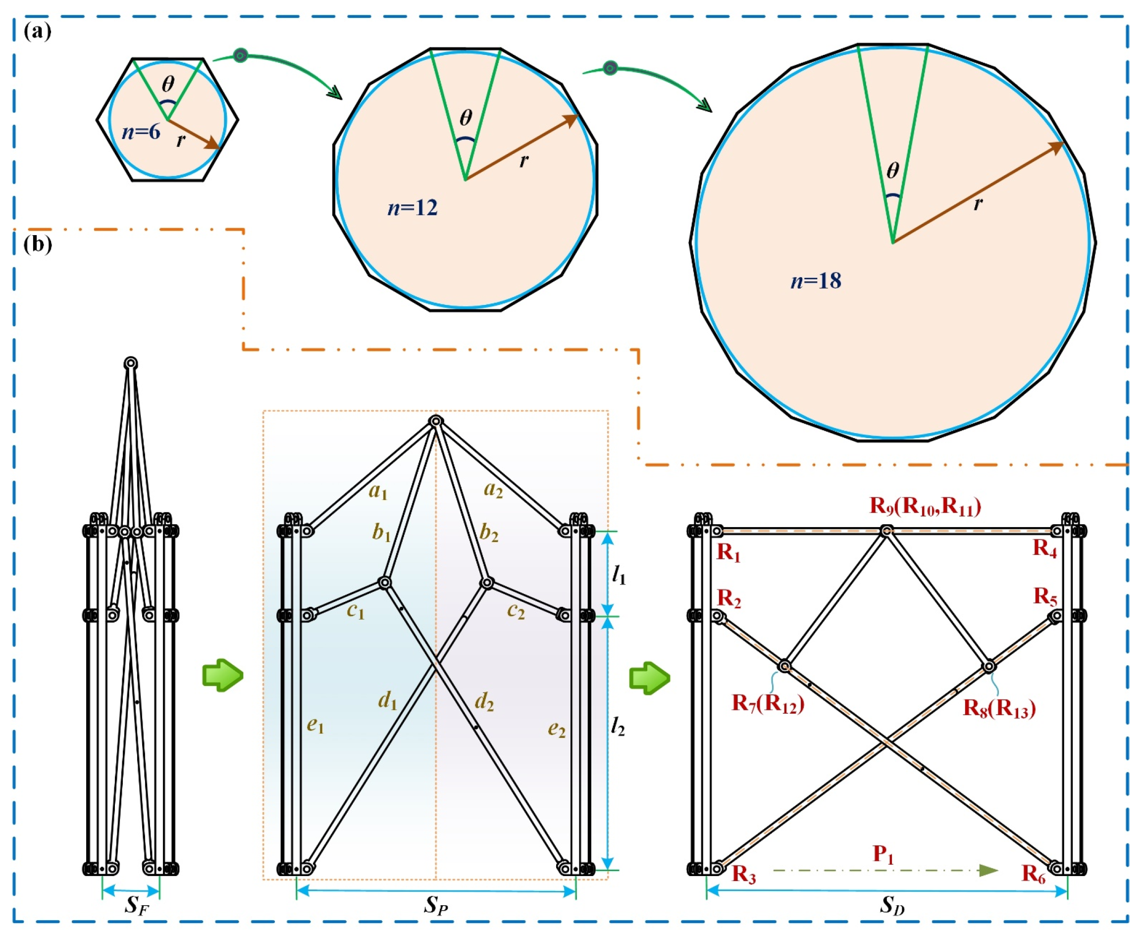
Large-span and ultra-large-span ring deployable perimeter trusses may encounter many difficulties in engineering. To reduce the difficulty of design and effectively control costs, modular design methods are usually adopted, which can greatly enhance the scalability of the ring deployable perimeter truss. Meanwhile, through proper assembly, the basic units can form aerospace mechanisms with different task requirements. Further, regular polygon approximation techniques are commonly used in the design process of ring deployable perimeter truss, as shown in Figure 2a; the approximation effect will become better as the number of sides increases, where n presents the number of sides of the polygon and each side is suitable as a basic unit for design. Based on the above analysis, the basic unit is designed as shown in Figure 2b, in which all the links are connected by revolute joints.
Here, link a1 is jointed to link a2 via a revolute joint (R9), link b2 is jointed to link a2 via a revolute joint (R11), and link a1 is jointed to link b1 via a revolute joint (R10). Moreover, link c1 is jointed to link d2 via a revolute joint (R12) and link c2 is jointed to link d1 via a revolute joint (R13). Further, link b1 is jointed to link c1 via a revolute joint (R7), and link b2 is jointed to link c2 via a revolute joint (R8). The connection of other links is as shown in Figure 2b. In addition, revolute joints (R1, R2, R7, R9) are used to form a single-mobility closed-loop planar 4R mechanism. Similarly, revolute joints (R4, R5, R8, R9) are used to form another single-mobility closed-loop planar 4R mechanism. These two sets of planar 4R mechanisms are coupled through a revolute joint (R9), so only one actuator is needed to drive them. Then, based on the modified Grübler–Kutzbach mobility criterion, the degree of freedom (M) about the basic unit can be obtained as follows:
M = d f n l g j 1 + i = 1 g j f i + ε r ξ l
where df is 3 for the planar mechanism; nl is the number of links, which is 10 in the basic unit; gj is the number of joints, which is 13 in the basic unit; fi is the degree of freedom (DOF) for the i-th joint; εr is the number of redundant constraints, which is 0 in the basic unit; and ξl is the local mobility, which also is 0 in the basic unit.
Then,
M = 3 10 13 1 + 13 = 1
The above equation shows that the basic unit is a single-mobility planar mechanism, which achieves relative movement between link e1 and link e2 as a prismatic joint (P1) shown in Figure 2b. In this case, revolute joints (R2, R12, R6) and a prismatic joint (P1) can be used to form a single-mobility closed-loop planar 3R1P mechanism, while revolute joints (R5, R13, R3) and the prismatic joint (P1) can also be used to form a single-mobility closed-loop planar 3R1P mechanism.
When the basic unit is in the folded state, revolute joints (R7, R1) and revolute joints (R8, R4) contact each other, and the distance between link e1 and link e2 is defined as SF. SF gradually increases during the deployment process. When the basic unit is in the fully deployed state, the axis of revolute joints (R1, R9, R4) are perpendicular to the same straight line; at the same time, the axis of revolute joints (R2, R12, R6) is perpendicular to the same straight line, and the axis of revolute joints (R5, R13, R3) is also perpendicular to the same straight line. In this case, revolute joints (R12, R13, R9) are precisely in a singular position; the basic unit cannot be further deployed at this point. The constraints of the entire basic unit have changed, and metamorphic motion occurs at this time. Unlike typical metamorphic mechanisms, metamorphic motion is used to convert one motion configuration into another motion configuration. Here, the metamorphic motion is used to form self-locking conditions and thus convert one motion configuration into a stable structure, which we also call metamorphic self-locking. This provides a new design concept for the stiffening process of mesh reflector deployable antennas.
In addition to the illustration of the mechanism principles, geometric models of the basic unit also need to be thoroughly studied. The basic unit is a highly symmetrical mechanism, and two sets of symmetrical and congruent right-angled triangles can be formed, so the following geometric relationship can be easily obtained:
( l c , 1 + l d , 2 ) 2 = ( l c , 2 + l d , 1 ) 2 = l 2 2 + S D 2
where l2 is shown in Figure 2b and SD presents the distance between link e1 and link e2 in the fully deployed state; lc,1 presents the length of link c1 and lc,2 presents the length of link c2; ld,1 presents the length of link d1 and ld,2 presents the length of link d2.
By using different Pythagorean numbers, different basic units can be built. For instance, if the length of links meets the following proportion:
l 2 : S D : ( l c , 2 + l d , 1 ) = 3 : 4 : 5
The lengths of other links within the basic unit satisfy the following geometrical relationship:
l a , 1 = l a , 2 = l b , 1 = l b , 2 = 0.5 S D l c , 1 = l c , 2 = l 1 = 0.5 l b , 1 = 0.5 l b , 2 l d , 1 = l d , 2 = 2 l b , 1 = 2 l b , 2 l e , 1 = l e , 2 = l 1 + l 2 = 2 l a , 1 = S D
where la,1 presents the length of link a1 and la,2 presents the length of link a2; lb,1 presents the length of link b1 and lb,2 presents the length of link b2; le,1 presents the length of link e1 and le,1 presents the length of link e2; l1 is shown in Figure 2b.
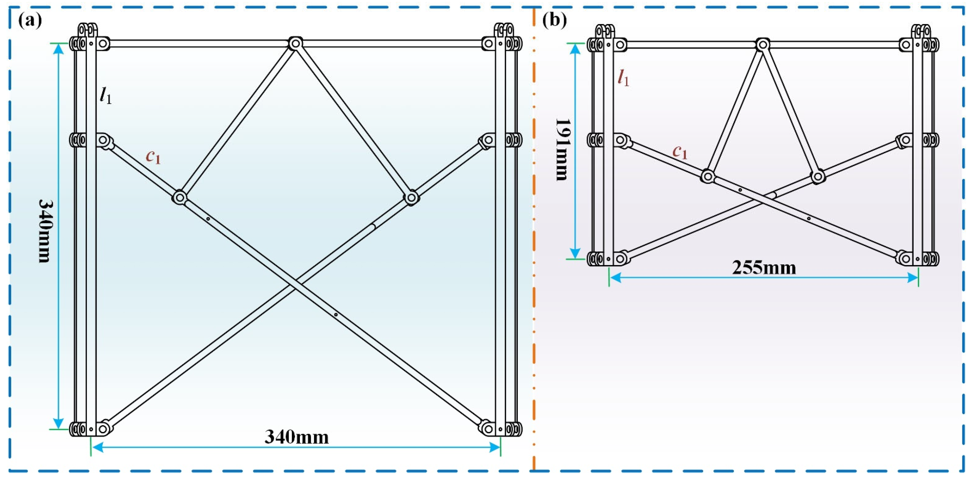
The generated basic unit is shown in Figure 3a. As a comparison, if the length of links meets the following proportion:
l 2 : S D : ( l c , 2 + l d , 1 ) = 5 : 12 : 13
The length relationship of other links needs to satisfy the following equation:
l a , 1 = l a , 2 = l b , 1 = l b , 2 = 0.5 S D l c , 1 = l c , 2 = l 1 = 0.5 l b , 1 = 0.5 l b , 2 l d , 1 = l d , 2 l e , 1 = l e , 2 = l 1 + l 2 = 2 l a , 1 = S D l 1 : l 2 = 4 : 5
The generated basic unit is shown in Figure 3b, where l1 and the length of link c1 in Figure 3a,b are equal, and we define l1 = lc,1 = 85 mm, but their height and width in the fully deployed state are quite different. Such features can be effectively applied to mesh antennas with different curvature radius, and further explanation on this issue will be mentioned later.

2.2. Geometric Modeling of the Ring Deployable Metamorphic Mechanism and Driving Method

After the basic unit, geometric modeling should also be further studied. Due to the modular design, the connection between the adjacent basic units cannot introduce additional degrees of freedom, so some links need to be shared, and the connection effect is shown in Figure 4. Link Ce corresponds to link e2 of the left basic unit and link e1 of the right basic unit. Because link Ce can be regarded as a rigid body without mobility, two adjacent basic units can move independently. By this method, multiple basic units can be sequentially connected to form the ring deployable metamorphic mechanism. Further, when the number of sides used is n, the central angle corresponding to each basic unit can be represented as:
θ = π ( n 2 ) n
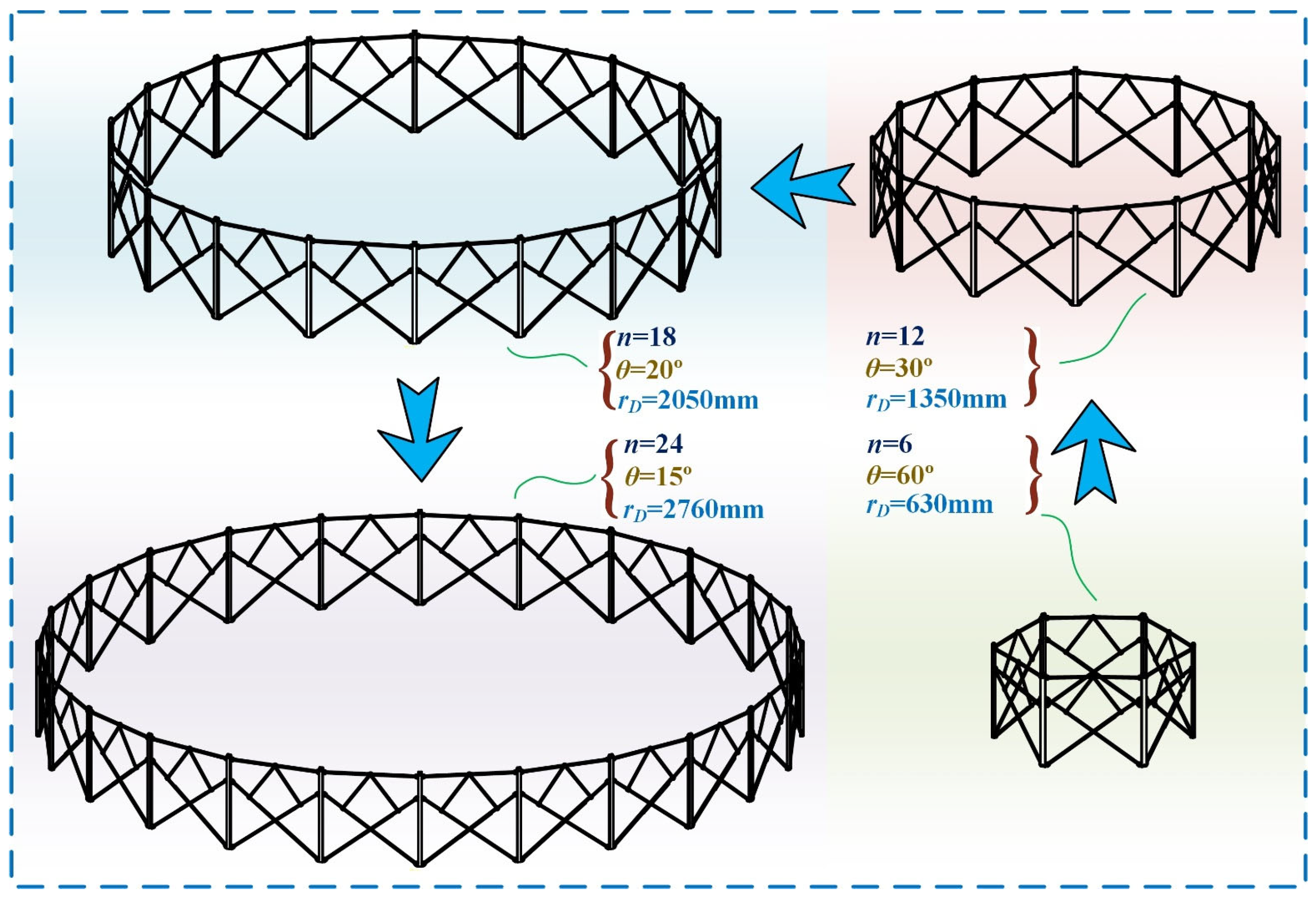
Therefore, the shared link Ce also requires a special design, as shown in Figure 4c; this connection method is more efficient compared to adding connecting links in reference [27]. Thus, the ultimate ring deployable metamorphic mechanism can be put together as illustrated in Figure 5, in which four different polygons are applied, including a regular hexagonal shape, a regular 12-sided shape, a regular 18-sided shape, and a regular 24-sided shape. As the number of sides increases, the diameter of the ring deployable metamorphic mechanism grows rapidly. Where the relationship between the deployable semidiameter and the number of sides of the polygon can be expressed:
r D = S D 2 tan θ 2 = S D 2 1 + cos θ sin θ
From the above equation, it can be seen that the deployable semidiameter is only related to two core parameters, including n and SD.
After completing the assembly of the ring deployable metamorphic mechanism, further study is needed on the driving method. Since the degrees of freedom of each basic unit are independent of each other, if each basic unit is driven independently, the number of actuators is equal to the number of sides; this is not feasible. In the previous driving method, a single prismatic joint is consistently utilized as the driving joint. Such a method can usually achieve good results in small-aperture mesh antennas due to the following reasons. On one hand, the small ring deployable mechanism often contains relatively few joints, which means there is less damping during the deployment process, so if the actuator can provide sufficient driving force, the ring deployable mechanism can be smoothly deployed. On the other hand, the ring deployable mechanisms are usually symmetrical structures, so there is a certain distance between the driving joint and the joint whose positions are relatively symmetrical, and this distance can increase as the size of the ring deployable mechanism increases.
In this case, the driving force, due to the influence of damping, will continuously decay during the transmission process, and then the asynchronous deployment motion of the ring deployable mechanism may occur. This is not allowed for the mesh reflector deployable antennas because it may not only cause damage to the ring deployable mechanism but also to the mesh structure. The simple solution for such a problem is to directly add actuators at different locations, which can change the transmission effect of force flow. Collaborative control of multiple actuators and rapidly increasing mass, however, will become difficult to handle.
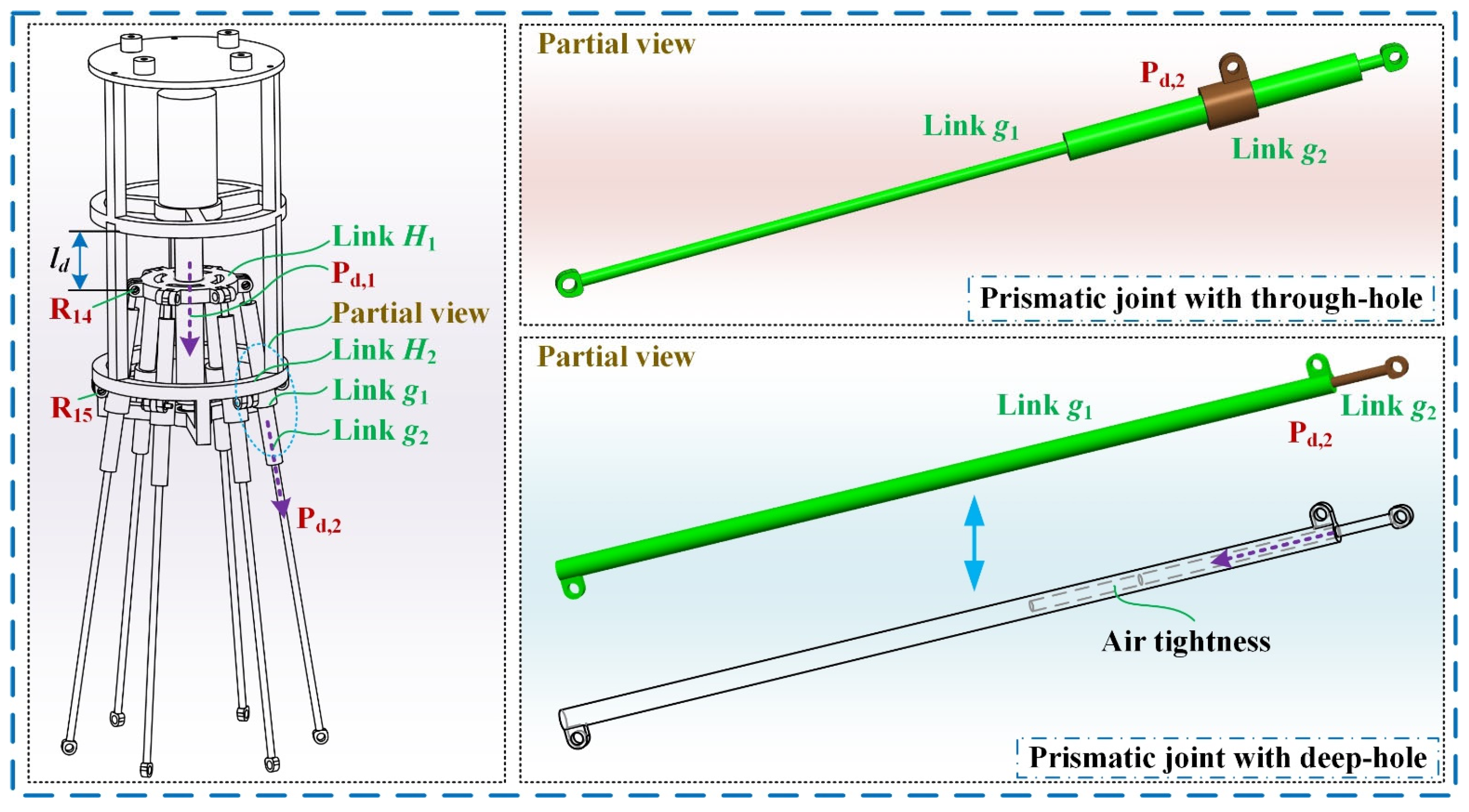
To effectively solve this problem, a single-mobility multi-point driving method has been proposed in reference [27], in which the prismatic joints of multiple single-mobility closed-loop planar 2R2P mechanisms are coupled to form a public prismatic joint (Pd,1) as shown in Figure 6. For the structures of the driving mechanism, the main improvement is the formation method of the prismatic joint (Pd,2) by changing the structure of link g1 and link g2, which is because we found that the formation method of the prismatic joint has a significant impact on the feasibility in previous physical prototype experiments. The prismatic joint (Pd,2) with deep holes has strong uncertainty during the motion process because deep holes are difficult to effectively lubricate and are prone to air tightness and damping. In contrast, the prismatic joint (Pd,2) with a through-hole has strong feasibility due to its well-lubrication effect; the final experimental prototype and deployable experiments also proved this point.
In the connecting process, the number of 2R2P mechanisms should be equal to the number of deployable basic units. Since this paper mainly focuses on the study of the regular hexagonal ring deployable mechanism, the driving mechanism also includes six identical 2R2P kinematic chains. Then, two adjacent links g1 of the driving mechanism can connect with the deployable basic unit of the ring deployable mechanism by revolute joints (R16,c1, R16,c2) as shown in Figure 7. As the connection between each basic unit and the driving mechanism is completed, the large-span ring deployable perimeter truss is formed. By a public prismatic joint (Pd,1), the entire perimeter truss can achieve both deployment and folded motions. An important advantage is that this driving method overcomes the problem of multiple degrees of freedom of the ring deployable metamorphic mechanism itself. Single-mobility driving is crucial for the light weight of large-span aerospace mechanisms. Moreover, the distance between each joint on the ring deployable metamorphic mechanism and the nearest driving joint is relatively short, which ensures that the driving force will not be excessively attenuated during the driving process and can effectively ensure the transmission efficiency of force flow. In addition, the driving mechanism can also improve the stiffness performance, which is very valuable for single-layer ring deployable mechanisms with large or ultra-large diameters. When the value of SD is 340 mm, the deployable process of the large-span ring deployable perimeter truss can be given. In the folded state, the bottom diameter of the outer envelope cylinder is close to 162 mm, and the height is close to 890 mm. As a comparison, the bottom diameter of the outer envelope cylinder is close to 745 mm, and the height is close to 690 mm in the fully deployed state, so there is a good deploy/fold ratio.

2.3. Structural Analysis and Evaluation Method

Currently, mesh reflector deployable antennas are gradually developing towards large and ultra-large apertures, which poses a great challenge to the transportation process due to the limited carrying capacity of the rockets. The inadequacy of this carrying capacity is manifested in multiple aspects. The first key point is that the size of mesh antennas cannot be too large, and the second key point is that the quality cannot be too large.
Here, it should be noted that mass issues may be caused by unreasonable materials applied or designs. In terms of materials, it needs to be determined according to actual needs, and there are relatively few parts that can be adjusted. In terms of design, the simplest possible structure and control system should be applied to achieve light weight. In the proposed design scheme, the deployable mechanism only includes one actuator and is formed by a simple planar linkage mechanism.
Apart from mass issues, a good deploy/fold ratio is an important performance index due to the use of deployable mechanisms, which means the perimeter truss has a compact folded state and a large deployed state. Where the compact folded state is used for storage and transportation, and the large deployed state is used for on-orbit operation. Further, the evaluation method for the deploy/fold ratio can be performed from three dimensions, including height ratio, radius ratio, and volume ratio. These three indicators can be used to comprehensively evaluate the deployment performance.
Here, δv,1 is defined to present the volume of the fully deployed state, and δv,2 is defined to present the volume of fully folded state; δd,1 is defined to present the diameter of fully deployed state, and δd,2 is defined to present the diameter of fully folded state; δh,1 is defined to present the height of fully deployed state, and δh,2 is defined to present the height of fully folded state. The deploy/fold ratio is assessed using three parameters: diameter ratio λv, height ratio λh, and volume ratio λd, which can be determined by:
λ v = δ v , 1 / δ v , 2 λ d = δ d , 1 / δ d , 2 λ h = δ h , 1 / δ h , 2
The parameters δv,1, δv,2, δd,1, δd,2, δh,1, and δh,2 can be calculated by:
δ d , 1 = S D sin θ 1 cos θ δ d , 2 = S F sin θ 1 cos θ
δ h , 1 = l d + l g , 1 sin μ min + l e , 1 δ h , 2 = l d + l g , 1 sin μ max + l e , 1
δ v , 1 = π ( 0.5 δ d , 1 ) 2 δ h , 1 = π S D sin θ 1 cos θ 2 l d + l g , 1 sin μ min + l e , 1 δ v , 2 = π ( 0.5 δ d , 2 ) 2 δ h , 2 = π S F sin θ 1 cos θ 2 l d + l g , 1 sin μ max + l e , 1
where μ is as shown in Figure 7 and μ = [μmin, μmax]; ld is defined by the structure depicted in Figure 6, which is also the driving distance in kinematic analysis; lg,1 represents the length of the link g1; SF is determined by the specific structure.
From the above equation, it can be seen that the length of link g1 is determined by the diameter; thus, one can obtain:
0.5 δ d , 1 = S D sin θ 1 cos θ = l 5 + l g , 1 cos μ min
where l5 is decided by the corresponding structure as shown in Figure 8b.
According to the analysis mentioned earlier, one can see that the diameters δd,1 and δd,2 of the large-span ring deployable perimeter truss are decided by the length of link a1, n, and the selected Pythagorean numbers; the heights δh,1 and δh,2 of the large-span ring deployable perimeter truss are decided by the fully deployed state of the ring deployable metamorphic mechanism and μ; and the volumes δv,1 and δv,2 of the large-span ring deployable perimeter truss are controlled by the diameters and the heights. The value of μ is consistently influenced by mechanical transmission and interference, which means its range typically remains constant. Moreover, the edge count of the ring deployable metamorphic mechanism often affects the surface precision of the mesh reflector deployable antenna. Therefore, altering the length dimension of link a1 is the primary method to enhance deployable performance. Naturally, other performance metrics must also be taken into account, leading to a comprehensive evaluation. In this paper, the large-span ring deployable perimeter truss with edges n = 6 and la,1 = 85 mm is used, with its minimum folded and fully deployed states illustrated in Figure 7. The results indicate that the deploy/fold ratio can achieve 16.4.

3. Key Performance Analysis of the Large-Span Ring Deployable Perimeter Truss

To better understand the mechanical characteristics of the large-span ring deployable perimeter truss, it is necessary to create kinematic and dynamic models to derive the core performance metrics. Furthermore, kinematic and dynamic simulations are also important methods for verifying the feasibility of the large-span ring deployable perimeter truss. The specific modeling and simulation are as follows.

3.1. Kinematic Analysis of the Large-Span Ring Deployable Perimeter Truss

Usually, the kinematic analysis should be first performed before dynamic modeling, so kinematic modeling is the foundation of dynamic modeling. For convenience, the kinematic diagram of the large-span ring deployable perimeter truss can be given as shown in Figure 8, where ld represents the driving distance and is determined by the actuator of the large-span ring deployable perimeter truss. Given the complete symmetry of the driving mechanism, it can be split into six identical kinematic chains. For modeling purposes, only one kinematic chain is chosen, with points o1 and E1 representing the end position. According to geometric relationships, points o1 and E1 concerning for the base coordinate system {o0-x0y0z0} can be given as:
P 0 o 1 = l 5 + l g , 1 cos μ , 0 , l d l g , 1 sin μ P 0 E 1 = l 5 + l g , 1 cos μ , 0 , l d l g , 1 sin μ l e , 1
where P 0 o 1 and P 0 E 1 represents the position vector; l5 is shown in Figure 8b.
To solve for the parameter μ, the following equation can be obtained by geometric relationships:
cos μ = ( l 3 l d ) / ( l 3 l d ) 2 + ( l 4 l 5 ) 2 sin μ = ( l 4 l 5 ) / ( l 3 l d ) 2 + ( l 4 l 5 ) 2
where l3 and l4 are as shown in Figure 8b, which are determined by a special structure.
From Equation (15), one can see that parameter ld is the only variable, which once again reveals the single-mobility characteristic of the large-span ring deployable perimeter truss. Using position analysis, the velocity and acceleration of points o1 and E1 can be determined by computing the first and second derivatives of Equation (13).
v 0 E 1 = P 0 E 1 t a 0 E 1 = 2 P 0 E 1 t 2 , v 0 o 1 = P 0 o 1 t a 0 o 1 = 2 P 0 o 1 t 2
where V 0 E 1 and V 0 o 1 represent the velocity vector; a 0 E 1 and a 0 o 1 represents the acceleration vector.
Based on the kinematic model, the simulation can be performed. Here, the driving velocity and driving acceleration are defined as l ˙ d = 2 mm / s and l ¨ d = 0 mm / s 2 . The end position, end velocity, and end acceleration of point E1 are simulated as shown in Figure 9a–c. Moreover, to verify the deploy/fold performance, the diameter ratio λd, height ratio λh, and volume ratio λv are also simulated, as shown in Figure 9d, by which one can see that the theoretical deploy/fold ratio is quite large.

3.2. Dynamic Analysis of the Large-Span Ring Deployable Perimeter Truss

Besides kinematic analysis, dynamic analysis can be performed in the following way. Here, the modeling idea in reference [27] is used, by which the link H1 can be divided into six identical sub-links. The length of each sub-link is defined as l5. Similarly, the link H2 can also be divided into six identical sub-links, and the length of each sub-link is defined as l4. Link H1 and link H2 are shown in Figure 6, each sub-link of link H1 is called link h1, and each sub-link of link H2 is called link h2. At this point, the dynamic modeling process is as follows.
Establishments of the base coordinate system and the local coordinate system are shown in Figure 8a. According to the lumped mass method, the centroid position of all the links for the large-span ring deployable perimeter truss needs to be determined first. For the driving mechanism, the position vector of each joint concerning the base coordinate system {o0-x0y0z0} can be expressed as:
P 0 P d , 1 = 0 , 0 , l d ; P 0 R 14 i = l 5 cos ( i 1 ) θ , l 5 sin ( i 1 ) θ , l d ; P 0 R 15 i = l 4 cos ( i 1 ) θ , l 4 sin ( i 1 ) θ , l 3 ; P 0 R 16 i = ( l 5 + l g , 1 cos μ ) cos ( i 1 ) θ , ( l 5 + l g , 1 cos μ ) cos ( i 1 ) θ , l d l g , 1 sin μ
where i represents the kinematic chains and i = 1, 2, …6; θ represents the exterior angle of a polygon as shown in Figure 2a.
For the i-th planar deployable basic unit shown in Figure 8c, the position vector of each joint concerning the local coordinate system {oi-xiyizi} (i = 1, 2, … 6) can be described as:
P i R 4 i = 0 , 0 , 0 ; P i R 1 i = 2 l a , 1 cos η 1 , 0 , 0 ; P i R 5 i = 0 , 0 , l 1 ; P i R 2 i = 2 l a , 1 cos η 1 , 0 , l 1 ; P i R 6 i = 0 , 0 , l e , 1 ; P i R 3 i = 2 l a , 1 cos η 1 , 0 , l e , 1 ; P i R 7 i = S P l c , 2 cos η 2 , 0 , l 1 + l c , 2 sin η 2 ; P i R 8 i = l c , 2 cos η 2 , 0 , l 1 + l c , 2 sin η 2 ; P i R 9 i = l a , 1 cos η , 0 , l a , 1 sin η ;
where η1 and η2 are as shown in Figure 8c; the position vectors including P i R 1 i , P i R 2 i , P i R 3 i , P i R 4 i , P i R 5 i , P i R 6 i , P i R 7 i , P i R 8 i , and P i R 9 i concerning the base coordinate system {o0-x0y0z0} can be calculated by:
P 0 R j i , 1 T = T i , 0 P i R j i , 1 T , i = 1 , 2 , , 6 j = 1 , 2 , 3 , , 9
where Ti,0 represents the transformation matrix from the local coordinate system {oi-xiyizi} to the base coordinate system {o0-x0y0z0}.
The transformation matrix Ti,0 contains two parts, including rotation and movement, which can be effectively expressed as:
T i , 0 = cos ( i 1 ) θ sin ( i 1 ) θ 0 l 5 + l g , 1 cos μ cos ( i 1 ) θ sin ( i 1 ) θ cos ( i 1 ) θ 0 l 5 + l g , 1 cos μ sin ( i 1 ) θ 0 0 1 l d l g , 1 sin μ 0 0 0 1
To examine the kinetic and potential energy, one can assume that the mass of all links can be concentrated at the centroid position for description. We define the plane {x0o0y0} as a zero-potential-energy surface in the dynamic model. Based on Equations (18) and (19), the central coordinate of each link can be described as:
P 0 c , a 1 i = 0.5 P i R 1 i + P i R 9 i P 0 c , a 2 i = 0.5 P i R 4 i + P i R 9 i ; P 0 c , b 1 i = 0.5 P i R 7 i + P i R 9 i P 0 c , b 2 i = 0.5 P i R 8 i + P i R 9 i ; P 0 c , c 1 i = 0.5 P i R 2 i + P i R 7 i P 0 c , c 2 i = 0.5 P i R 8 i + P i R 5 i P 0 c , d 1 i = 0.5 P i R 7 i + P i R 6 i P 0 c , d 2 i = 0.5 P i R 8 i + P i R 3 i ; P 0 c , e 1 i = 0.5 P i R 1 i + P i R 3 i P 0 c , e 2 i = 0.5 P i P 4 i + P i R 6 i ; P 0 c , g 1 i = 0.5 P i R 14 i + P i R 16 i P 0 c , g 2 i = P i R 15 i ; P 0 c , h 1 i = 0.5 P i R d , 1 i + P i R 14 i P 0 c , h 2 i = 0.5 l 4 , 0 , l 3
where the vectors, including P 0 c , a 1 i , P 0 c , a 2 i , P 0 c , b 1 i , P 0 c , b 2 i , P 0 c , c 1 i , P 0 c , c 2 i , P 0 c , d 1 i , P 0 c , d 2 i , P 0 c , e 1 i , and P 0 c , e 2 i , represent the centroid coordinate of the links for the i-th kinematic chain.
The translational velocity of each link for the i-th kinematic chain concerning the base coordinate system {o0-x0y0z0} can be calculated by:
v 0 c , a 1 i = P 0 c , a 1 i t v 0 c , a 2 i = P 0 c , a 2 i t ; v 0 c , b 1 i = P 0 c , b 1 i t v 0 c , b 2 i = P 0 c , b 2 i t ; v 0 c , c 1 i = P 0 c , c 1 i t v 0 c , c 2 i = P 0 c , c 2 i t v 0 c , d 1 i = P 0 c , d 1 i t v 0 c , d 2 i = P 0 c , d 2 i t ; v 0 c , e 1 i = P 0 c , e 1 i t v 0 c , e 2 i = P 0 c , e 2 i t ; v 0 c , g 1 i = P 0 c , g 1 i t v 0 c , g 2 i = P 0 c , g 2 i t ; v 0 c , h 1 i = P 0 c , h 1 i t v 0 c , h 2 i = P 0 c , h 2 i t
Additionally, the rotational velocity of each link can be described as:
ω 0 c , a 1 i = ω 0 c , a 2 i = η ˙ 1 ω 0 c , c 1 i = ω 0 c , c 2 i = η ˙ 2 ω 0 c , b 1 i = ω 0 c , b 2 i = η ˙ 3 ω 0 c , b 1 i = ω 0 c , b 2 i = η ˙ 4 ω 0 c , e 1 i = ω 0 c , e 2 i = 0 ; ω 0 c , g 1 i = ω 0 c , g 2 i = μ ˙ ω 0 c , h 1 i = ω 0 c , h 2 i = 0
where η ˙ 1 , η ˙ 2 , η ˙ 3 , η ˙ 4 , and μ ˙ are the first-order derivative of η1, η2, η3, η4, and μ, which are as shown in Figure 8c.
These parameters, including η ˙ 1 , η ˙ 2 , η ˙ 3 , η ˙ 4 , and μ ˙ , can be obtained by the following equations:
η ˙ 1 = η 1 t = t ( arccos 0.5 S P l a , 1 ) η ˙ 2 = η 2 t = t π 2 2 arccos l 1 2 + l 1 l a , 1 sin ( η 1 ) l 1 l 1 2 + l a , 1 2 + 2 l 1 l a , 1 sin ( η 1 ) η ˙ 3 = η 3 t = t π 2 + η 1 π ( π 2 η 2 ) = t ( η 1 η 2 ) η ˙ 4 = η 4 t = t π 2 arctan l 2 S P arccos ( l d , 1 2 + ( l 2 2 + S P 2 ) l 1 2 2 l d , 1 ( l 2 2 + S P 2 ) ) μ ˙ 4 = μ 4 t = t arccos ( l 3 l d ) / ( l 3 l d ) 2 + ( l 4 l 5 ) 2
Here, ld is identified as the generalized coordinate, and according to the Lagrange equation, the dynamic model for the large-span ring deployable perimeter truss can be expressed as:
t ( L l ˙ d ) ( L l d ) = Q
where L is the Lagrange function and L = EU; E represents kinetic energy; U represents potential energy; and Q represents a generalized force.
Then, kinetic energy and potential energy of the large-span ring deployable perimeter truss concerning the base coordinate system {o0-x0y0z0} can be calculated by:
E = 1 2 i = 1 6 m i k ( v 0 c , k i ) 2 + 1 2 i = 1 6 J i k ( ω 0 c , k i ) 2 U = i = 1 6 m i k g P 0 c , k z , i
where k = [link a1, link a2, link b1, link b2, link c1, link c2, link d1, link d2, link e1, link e2, link g1, link g2, link h1, link h2]. m i k represents the mass of link k in the i-th kinematic chain; J i k represents the rotational inertia of link k in the i-th kinematic chain; P 0 c , k z , i presents the z-coordinate of link k in the i-th kinematic chain concerning the base coordinate system {o0-x0y0z0}; g presents gravitational acceleration.
Moreover, friction and other disruptions are significant factors in this process. The generalized forces related to viscous friction can be described by defining cR as the coefficient for revolute joints and cP as the coefficient for prismatic joints. The related generalized forces can be represented by:
f R = 12 c R ( 2 η ˙ 1 + 2 η ˙ 2 + 2 η ˙ 3 + 2 η ˙ 4 + 3 μ ˙ ) f P = c P ( l ˙ d + v 0 c , g 1 i )
where fR denotes the generalized force resulting from revolute joints, while fP denotes the generalized force resulting from prismatic joints.
Then, the total generalized force Q of the large-span ring deployable perimeter truss can be given as:
Q = τ f R f P F C
where τ presents the driving force of the large-span ring deployable perimeter truss; FC presents the total prestress by cable-net structure, which will be further studied in the next section.
As a result, all dynamic terms have been acquired, allowing the dynamic model of the large-span ring deployable perimeter truss to be presented as follows:
t ( L l ˙ d ) L l d + f R + f P + F C = τ
To verify the dynamic model of the large-span ring deployable perimeter truss, a dynamic simulation needs to be performed. Here, the fundamental parameters can be determined using the three-dimensional model. The main material of each link is aluminum alloy with the density ρa = 2.71 × 10³ kg/m3, the material of the driving joint is brass with the density ρb = 8.5 × 10³ kg/m3, the material of the servo motor is stainless steel with the density ρs = 7.93 × 10³ kg/m3, the value of gravitational acceleration is 9.8 m/s2, the viscous friction coefficient of revolute joints is defined as cR = 0.2 Nms/rad, and the prismatic joint is cP = 0.2 Nms/rad. The dynamic simulation can be done as shown in Figure 9e,f.

4. Design of Cable-Net Structure Used for the Large-Span Ring Deployable Perimeter Truss

Design of the cable-net structure is an important part of the mesh reflector deployable antenna; a reasonable cable-net structure design is a significant guarantee for the correct prestress distribution and an important path to maintain the surface accuracy. Further, the cable-net structure needs to consider the particularity of the large-span ring deployable perimeter truss, in which effective connection methods also need to be discussed. This section will start from the large-span ring deployable perimeter truss to design a suitable cable-net structure. The specific contents are as follows.

4.1. Mathematical Modeling and Prestressing Analysis for Cable-Net Structure

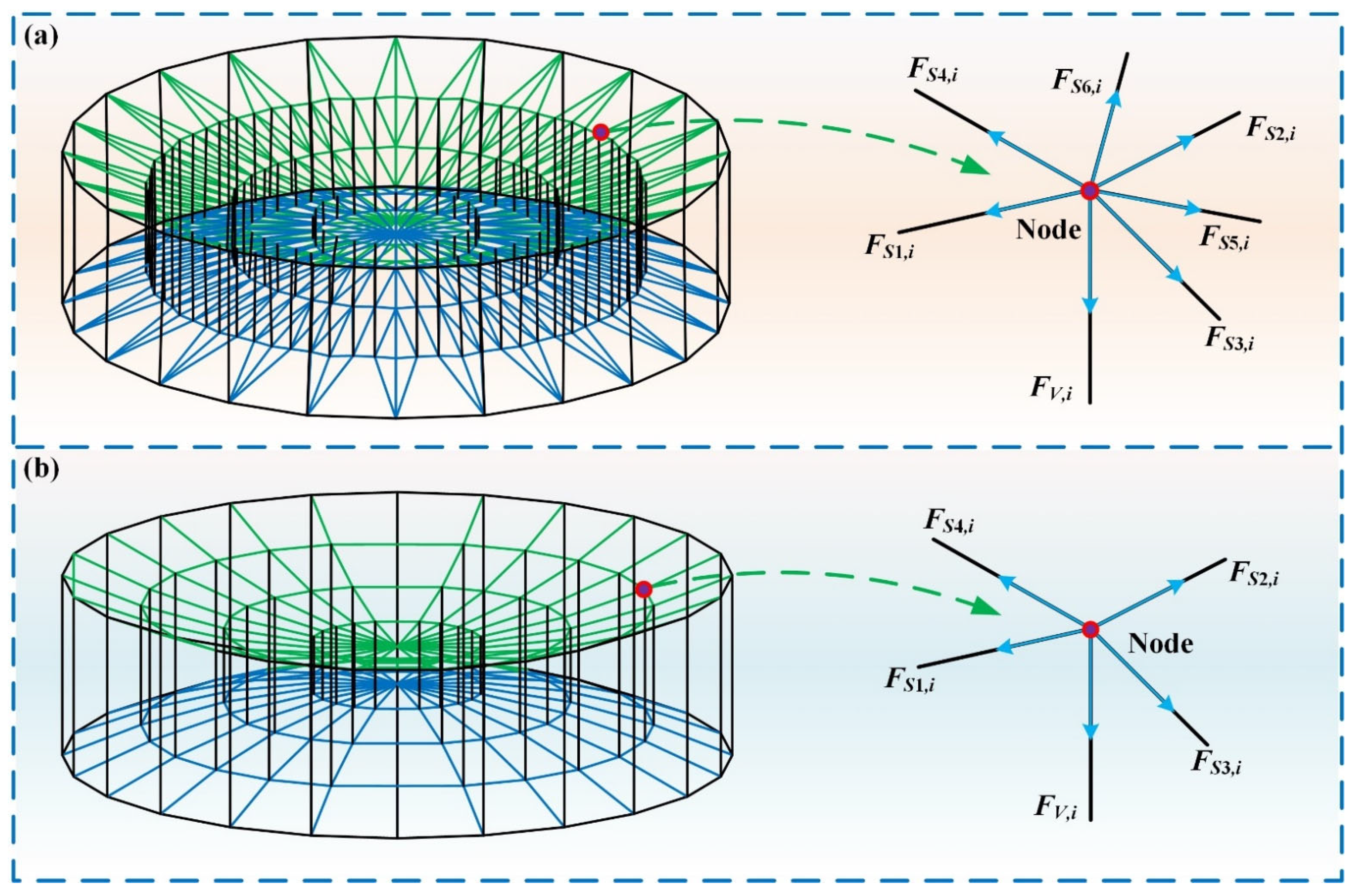
Cable-net structure used for mesh reflector deployable antenna has various forms, in which the most common forms are triangular cable-net structure and cable-arch structure due to their excellent performance, as shown in Figure 10. The triangular cable-net structure has excellent structural stability, but the connections between adjacent cable segments are relatively complex, in which each node is connected by seven cable segments. As a result, the reflector contains many nodes, and solving for prestress is relatively difficult, as shown in Figure 10a. This is a good choice for an ultra-large aperture mesh reflector deployable antenna. By contrast, the cable-arch structure is simpler, and each node is connected by five cable segments, as shown in Figure 10b. The prestress distribution of the cable-arch structure is also uncomplicated and easier to calculate, which is an important advantage. In addition, the connection between the cable-arch structure and the large ring deployable perimeter truss is easy to achieve. Based on the above analysis, the mathematical modeling of the cable-arch structure used for the large-span ring deployable perimeter truss will be established as follows.
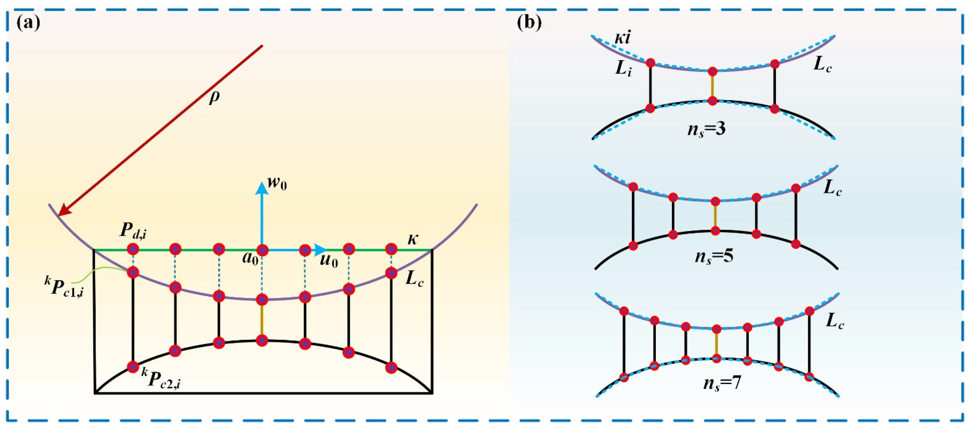
The cable-net structure is closely related to the type of the mesh reflector deployable antenna, which can be mainly divided into two types, including cylindrical surface antenna and spherical surface antenna. Here, cylindrical surface antennas typically require a rectangular deployable perimeter truss, while spherical surface antennas typically require a ring deployable perimeter truss. To achieve compatibility with the proposed large-span ring deployable perimeter truss, spherical surface antennas are selected as study objects. As shown in Figure 11a, the curvature radius of the spherical surface antenna is defined as ρ, the deployable radius of the inner circle for the large-span ring deployable perimeter truss can be regarded as a chord κ in the main view, and the arc corresponding to the chord κ can be identified as Lc. Usually, when dividing the grid, the chord κ is divided into several equal segments, or the arc Lc is divided into several equal segments to determine the number of nodes. The number of nodes is closely related to the surface accuracy of the mesh reflector deployable antenna. As the number of nodes increases, the cable-net structure becomes more complex, and the surface accuracy can be quickly improved. Moreover, when the cable-net structure is relatively complex, the requirements for the large-span ring deployable perimeter truss will also increase, such as stiffness performance. Taking equal chord lengths as an example, when the chord κ is divided into ns segments, the approximation effect of the arc is shown in Figure 11b; the more segments there are, the better the approximation effect. However, the complexity of the cable-net structure will also increase rapidly with too many segments. Therefore, the number of nodes needs to be considered comprehensively. Moreover, it should be emphasized that the number of nodes also determines the number of longitudinal cables. For a group of cable-arch structures, the number of longitudinal cables is usually odd. In this way, multiple groups of cable-arch structures can share a longitudinal cable at the center position, which has a certain impact on the stability of the cable-net structure.
Based on the above analysis, the Cartesian coordinate system {a0-u0v0w0} can be established as shown in Figure 11a. The chord κ for the large-span ring deployable perimeter truss is divided into equal ns parts, where κi (i = 1, 2, …, ns) presents the length of the sub-chord and Li (i = 1, 2, …, ns) presents the length of the sub-arc. Meanwhile, Pd,i (i = 1, 2, …, ns) presents the equal-part point of chord κ, kPc1,I (i = 1, 2, …, ns) presents projection point in front net corresponding to equal-part point Pd,i, and kPc2,i (i = 1, 2, …, ns) presents projection point in rear net corresponding to equal-part point Pd,i. Assuming that there are kg groups of cable-arch structures, the total number of nodes Nnodes can be calculated by:
N n o d e s = ( n s 1 ) k g + 2
For nodes kPc1,i or kPc2,i (k = 1, 2, …, kg) in a cable-net structure, the following equation based on the static equilibrium can be given as:
F S 1 , i u 0 k + F S 2 , i u 0 k + F S 3 , i u 0 k + F S 4 , i u 0 k + F V , i u 0 k = 0 F S 1 , i v 0 k + F S 2 , i v 0 k + F S 3 , i v 0 k + F S 4 , i v 0 k + F V , i v 0 k = 0 F S 1 , i w 0 k + F S 2 , i w 0 k + F S 3 , i w 0 k + F S 4 , i w 0 k + F V , i w 0 k = 0
where F S 1 , i u 0 k , F S 2 , i u 0 k , F S 3 , i u 0 k , F S 4 , i u 0 k , and F V , i u 0 k present the component of prestress F S 1 , i k , F S 2 , i k , F S 3 , i k , F S 4 , i k , and F V , i k in the u0-axis direction; F S 1 , i v 0 k , F S 2 , i v 0 k , F S 3 , i v 0 k , F S 4 , i v 0 k , and F V , i v 0 k present the component of prestress F S 1 , i k , F S 2 , i k , F S 3 , i k , F S 4 , i k , and F V , i k in the v0-axis direction; F S 1 , i w 0 k , F S 2 , i w 0 k , F S 3 , i w 0 k , F S 4 , i w 0 k , and F V , i w 0 k present the component of prestress F S 1 , i k , F S 2 , i k , F S 3 , i k , F S 4 , i k , and F V , i k in the w0-axis direction.
In the ideal condition, we often have F S 3 , i k = F S 4 , i k and F V , i u 0 k = F V , i v 0 k = 0 . However, due to various factors, the values of these prestresses do not meet the ideal conditions in the actual physical model, so local adjustments are still needed to reach the requirements.
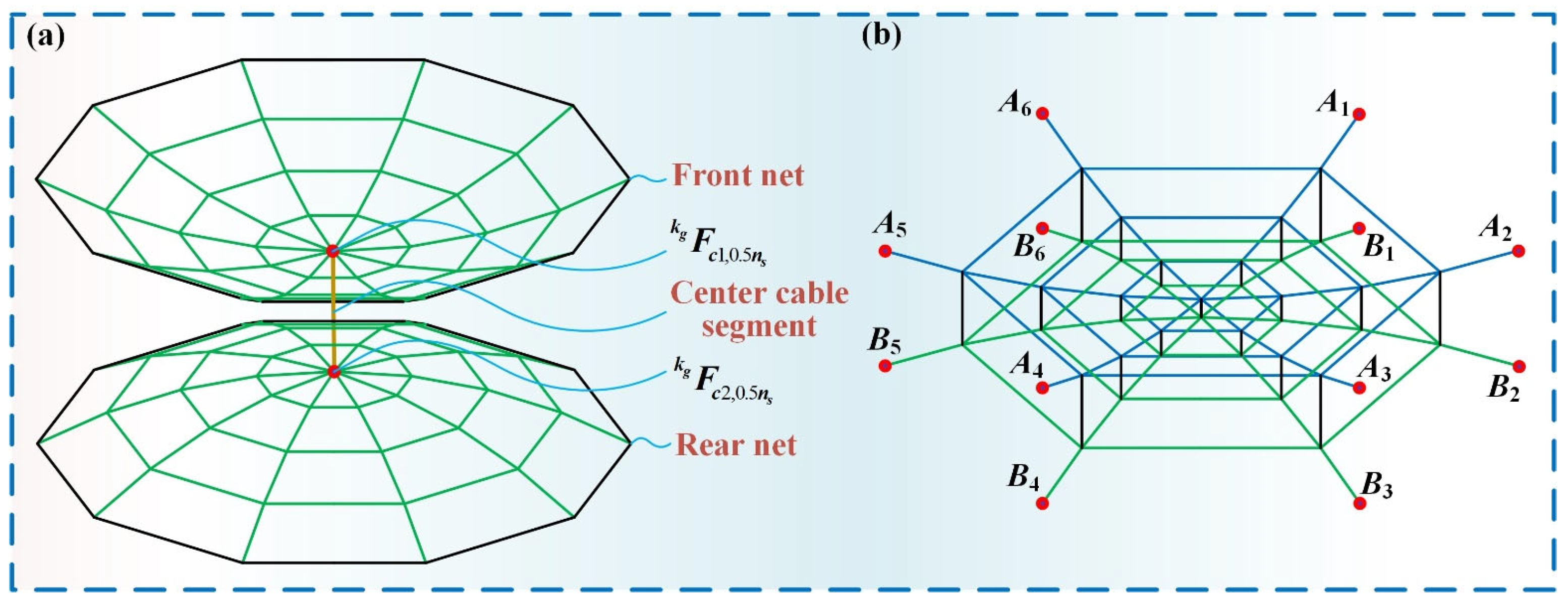
Further, for two common nodes F c 1 , 0.5 n s k or F c 2 , 0.5 n s k in a cable-net structure, as shown in Figure 12a, the static equilibrium model can be expressed as:
k = 1 k = k g F S u 0 k + F V , 0.5 n s u 0 k g = 0 k = 1 k = k g F S v 0 k + F V , 0.5 n s v 0 k g = 0 k = 1 k = k g F S w 0 k + F V , 0.5 n s w 0 k g = 0
Considering that the number of prestress and the number of cable segments are the same, the prestress of each node can be integrated into a matrix, which can be expressed as:
B N n o d e s × c s F c s × 1 = 0 N n o d e s × 1
where cs presents the total number of cable segments; F c s × 1 presents the prestress vector; B N n o d e s × c s and presents the prestress balanced matrix.
For a mesh reflector deployable antenna, the node positions are usually determined first in the original design, which means that the balanced matrix B N n o d e s × c s is invariant. Therefore, the problem of prestress analysis is converted into a solution problem for the above homogeneous linear equation system, which requires that the prestress of each cable segment belong between the maximum and minimum prestress allowed by the cables. This is because all cable segments in the cable-net structure must be prestressed to form a rigid shape. If there is a relaxation of the cable segments, it will affect the surface accuracy of the mesh satellite antenna.
The solution of prestress can generally be divided into two main steps. Firstly, the orthogonal basis in the zero-space of the homogeneous linear equation system is solved. Then, the prestress can be expressed as a linear combination of these orthogonal bases. Secondly, the set of optimal solutions can be found through optimization. The orthogonal basis in zero-space of the equilibrium equation system is usually obtained by singular value decomposition as:
B N n o d e s × c s = S 0 0 0 V H
where S presents a Nnodes-order orthogonal matrix; V presents a cs-order orthogonal matrix; Σ presents an rc-order diagonal matrix composed of rc singular values of the matrix B N n o d e s × c s , in which rc is the rank of the matrix B N n o d e s × c s .
Assuming that:
k c = c s r c
where kc presents the number of prestress modes.
The right kc column of matrix V can be expressed as V c s × k c m u l l , the specific form of which can be given as:
V c s × k c m u l l = [ V r c + 1 , V r c + 2 , V c s ]
where V r c + 1 , V r c + 2 , …, V c s presents the basis vector in zero-space.
According to the theory of linear algebra, the following equation can be obtained:
B N n o d e s × c s V c s × k c m u l l = 0
At this point, the orthogonal basis in zero-space of the B N n o d e s × c s matrix can be used to represent the prestress, the equation can be given as:
F c s × 1 = V c s × k c m u l l α k c × 1
where α k c × 1 presents a column vector of linear combination coefficients.
The rank of the balanced matrix needs to satisfy:
r c min ( N n o d e s , c s )
Based on the above analysis, there are three types of prestress mode numbers. First, when kc = 0, this equation has no solution, so there is no required prestress. Second, when kc = 1, this equation has only one set of solutions, which can be expressed as:
F c s × 1 = α 1 V r c + 1
If the boundary conditions required for prestress are met, the antenna can be deployed into the desired shape under this set of prestress. If the boundary conditions for prestress are not met, the antenna cannot be deployed into the desired shape.
Third, when kc > 1, there are multiple sets of solutions for the desired cable-net structure, and it is necessary to find the optimal solution through optimization methods. The constraint condition for cable-net structure is usually that the prestress of each cable segment should be between the maximum and minimum allowable values. The prestress optimization model can be summarized as follows:
find   α 1 , α 2 , α k c min f = ( F c s × 1 F ¯ c s × 1 ) H ( F c s × 1 F ¯ c s × 1 ) s . t .   F min < F i < F max C E × k c α k c × 1 = 0 E × 1
where α 1 , α 2 , and α k c present a column vector composed of linear combination coefficients; Fmax presents the maximum allowable value of prestress; Fmin presents the minimum allowable value of prestress; Fi presents the i-th prestress; C E × k c presents a symmetric constraint matrix; E presents the number of symmetric constraint equations; F ¯ c s × 1 presents a vector composed of the mean value of prestress.
The same group of cable segments has the same mean value, which can achieve uniform prestress. Assuming that the cable segments are symmetrical, then:
F p = a 1 V r c + 1 , p + a 2 V r c + 2 , p + + a k c V c s , p
F q = a 1 V r c + 1 , q + a 2 V r c + 2 , q + + a k c V c s , q
where V r c + 1 , p , V r c + 2 , p , V r c + 1 , q , and V r c + 2 , q separately present the p component and q component of prestressing modal vectors.
Subtracting the above two equations yields the following equation:
( V r c + 1 , p V r c + 1 , q ) a 1 + ( V r c + 2 , p V r c + 2 , q ) a 2 + + ( V c s , p V c s , q ) a k = 0
The corresponding row of the matrix can be obtained as follows:
[ ( V r c + 1 , p V r c + 1 , q ) , ( V r c + 2 , p V r c + 2 , q ) , , ( V c s , p V c s , q ) ]
By processing and solving all symmetrical cable segments of the cable-net structure, the optimal prestress distribution of the mesh reflector deployable antenna can be obtained. The difference between the maximum and minimum prestress obtained through this method is not significant, which makes the prestress distribution more balanced and the stiffness of the antenna surface more uniform. The load-bearing capacity of different surface areas is roughly equivalent. This has an important impact on the stability of the mesh reflector deployable antenna. At the same time, a good prestress distribution can also prevent fatigue fracture of the cable segment, which can affect the operation and communication quality. For the cable-net structure in this paper, seven longitudinal cables are arranged in each group of cable-arch structures, and six groups of cable-arch structures are used in the cable-net structure, as shown in Figure 12b.

4.2. Connection Method of the Cable-Net Structure and the Large-Span Ring Deployable Perimeter Truss

For the connection method of the cable-net structure and the large-span ring deployable perimeter truss, the structural characteristics of the large-span ring deployable perimeter truss need to be fully considered. In theory, the number of groups in cable-arch structures is not limited by the large-span ring deployable perimeter truss but only depends on the accuracy required by the mesh reflector deployable antenna. However, due to the deployable design and modular design on each side of the polygon, the links in the middle of each basic unit move complexly during the deployable process, and it is not easy to set connection points with a cable-net structure. Therefore, in practical operation, connection points are usually set on links that only have translational motion as shown in Figure 2b, in which the link e1 and link e2 of each basic unit are translational motion, while other links are Coriolis motion. It is obvious that this also means that the number of groups in the cable-arch structure is equal to half of the number of sides in the polygon, as shown in Figure 13b.
The connection of cable-net structures can be divided into the connection of cable segments and the connection with the large-span ring deployable perimeter truss. For the connection of the cable segments, different cable segments on the same node are compressed by a set of gaskets, while longitudinal cable segments are compressed through the central hole, as shown in Figure 13a. Then, multiple sets of symmetrical connection holes are set on the link e1 and link e2; the cable-net structure can then be connected with the large-span ring deployable perimeter truss through these connection holes, as shown in Figure 13b.

5. Physical Prototype, Control System, and Deployable Experiment

The feasibility verification is an important part of mechanism design and a key step for theoretical design to move towards practical application. Based on this idea, this section first carried out the design of the physical prototype and the cable-net structure. Further, the control system is established, and the control software is then well developed based on the Python 3.10 programming language, the corresponding functional analysis of which is executed simultaneously. In the end, deployable experimental verification of the large-span ring deployable perimeter truss is performed. The specific contents are as follows.

5.1. Design of the Physical Prototype and Mesh Structure

For the large-span ring deployable perimeter truss, design of the physical prototypes needs to fully consider the issue of lightweight. Currently, the main method of lightweight is to change the material or structure, but the structure is usually not subject to arbitrary changes. In engineering practice, the large-span ring deployable perimeter truss of the mesh reflector deployable antennas is always made up of carbon fiber composite material, the joint is often made up of titanium alloy material, and the cable-net structure is usually made up of ultra-high molecular weight polyethylene fiber. In addition, polyarylester fiber and metal-coated fiber can also be used to construct the cable-net structure. The above materials have very low quality but good stiffness, and they are thus suitable for space missions. However, the cost of these materials is too high, and the purpose of the experiments in the manuscript is mainly to verify the feasibility of large-span ring deployable perimeter truss, so we have chosen more economical engineering materials such as aluminum alloys and aramid fiber.
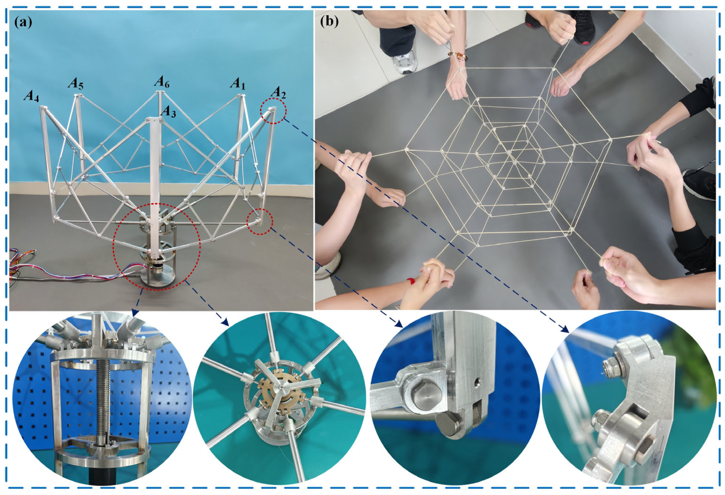
Unlike theoretical design, the engineering physical prototype needs to consider the effects of many factors, such as mechanical interference and scale parameters. Here, to weaken the influence of its own gravity, defining that the aperture of the large-span ring deployable perimeter truss in the fully deployed state is 600 mm; scale parameters of the corresponding links are shown in Table 1, where the impact caused by the links themselves has been taken into consideration, so the actual inscribed ring is slightly larger than the theoretical requirement. Moreover, considering that the deployable experiment was conducted in a gravitational environment, the effects generated by gravity need to be suppressed. This requires the large-span ring deployable perimeter truss to be lighter in design, while the driving mechanism needs to have sufficient stiffness performance. After comprehensive consideration, including copper alloy, stainless steel, aluminum alloys, and many other common engineering materials, the material of the links for the ring deployable metamorphic mechanism is aluminum alloy, the material of the links for the driving mechanism is stainless steel, the material of nut-screw is brass, and final physical prototype of the large-span ring deployable perimeter truss is shown in Figure 14a; the design details of the joints connecting are shown in the partial view.
In the design of the flexible cable-net structure, aramid fiber is used for the cables, which have good strength and elasticity, and it is widely used in the design of mesh antennas. Scale parameters of cables based on the designing method in Section 4 are shown in Table 2, where seven longitudinal cables are arranged in each group of cable-arch structures with equal length. Further, in the connection of the cable, a buckle is well designed, by which adjacent cables can be effectively connected and the cable-net structure can be formed as shown in Figure 14b. Finally, the cable-net structure is fixed on the large-span ring deployable perimeter truss. In engineering practice, the cable-net structure in practical applications is very dense compared to the physical prototype in the experimental environment, which is because the experimental environment is more focused on verifying whether the design theory of the cable-net structure can meet the requirements of mechanical equilibrium, so a slightly simpler cable-net structure can simplify the verification process.

5.2. Establishment of Control System

Based on the previous mechanism design, the prismatic joint (Pd,1) is used as the driving joint. Incorporating servomotor and nut-screw pairs into the large-span ring deployable perimeter truss has been shown to create the most precise actuator. Table 3 displays the main driving parameters of the servomotor. For nut-screw pairs, the material of the nut for the driving mechanism is brass, and the material of the screw for the driving mechanism is stainless steel. Such a method can more effectively ensure the smooth motion of the nut-screw pair.
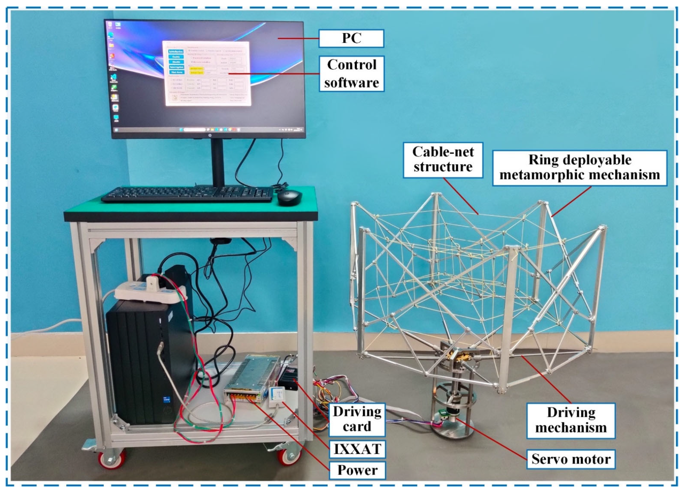
Moreover, the overall layout of the control system utilizing a controller area network (CAN) bus is effectively structured and the control software is then well developed based on the Python 3.10 programming language, as shown in Figure 15. In this system, a host PC transmits and receives commands. It then links to a driving card via a USB-CAN interface transmission module. The driving card is another module that manages data transmission and reception to control the servomotor. The final deployable experimental platform is shown in Figure 16.

5.3. Deployable Experimental Verification

The comprehensive study on mesh reflector deployable antennas involves multiple factors such as electromagnetic interference, microgravity field, and thermodynamics, which is a complex and interdisciplinary study. Therefore, full-scale and environmental testing, such as vacuum chamber and vibration testing, are essential but require specific equipment and considerable resources. The focus of this paper, however, is to design and analyze the proposed large-span ring deployable perimeter truss. The core validation is the study of its deployable performance. The physical prototype testing in our study primarily focused on validating the fundamental functionality and initial performance of the large-span ring deployable perimeter truss, which includes the feasibility testing and the stability testing. Once the core design and the basic functionality have been verified, full-scale and environmental testing are typically performed in later stages.
As can be seen, the host computer sends control commands to the USB-CAN interface transmission module to control the movement of the deployable mechanism. In addition, the object-oriented programming language Python is first used to write control software, such as a process that requires full consideration of various driving methods, such as position control, velocity control, and acceleration control. Secondly, other functions such as the initialization process, interrupt response, and data storage also need to be designed. Thirdly, the data input window and real-time data display window need to be reflected on the control interface. As a result, the final control interface of the large-span ring deployable perimeter truss is designed.
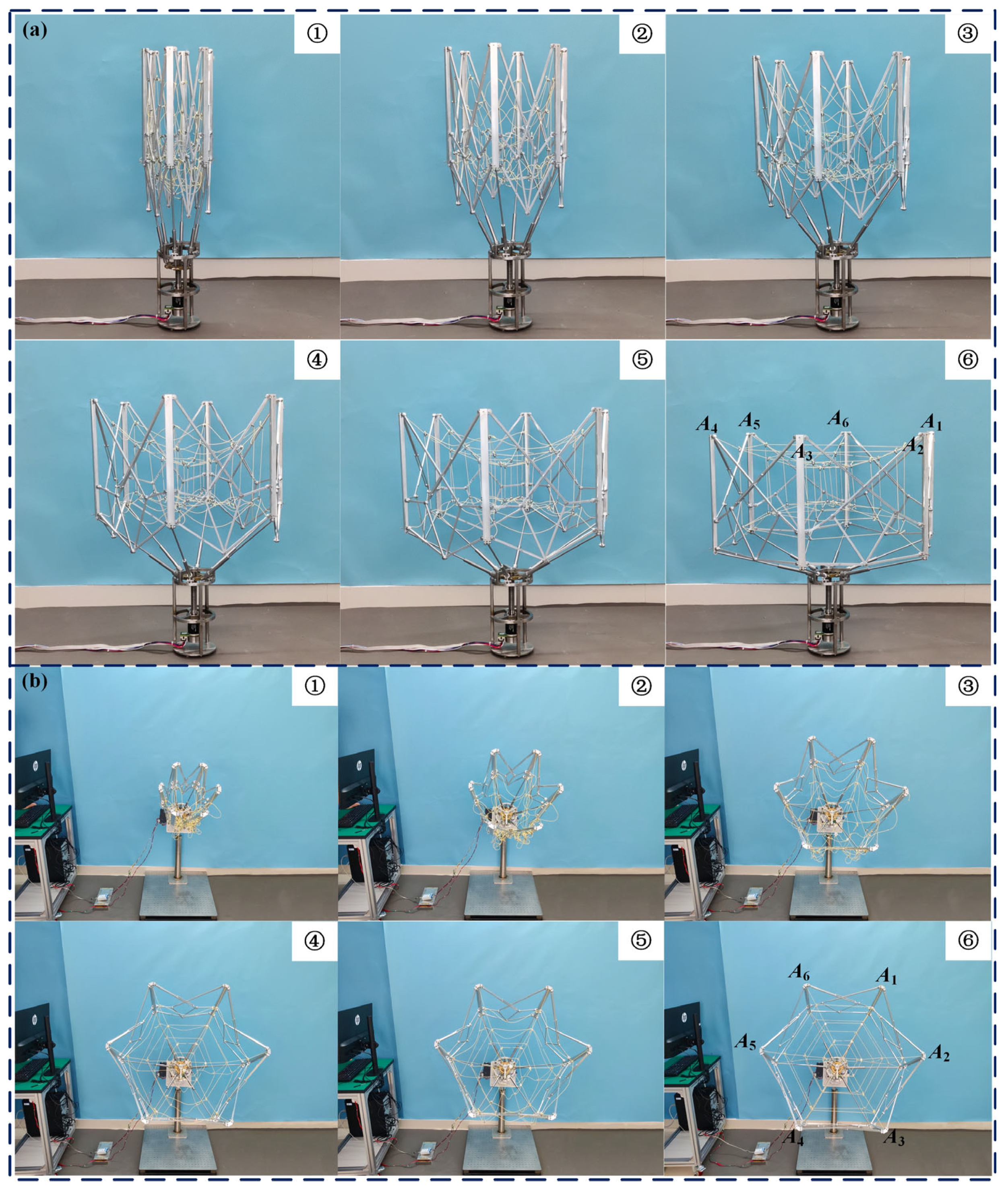
In deployable experiments, the feasibility verification of the large-span ring deployable perimeter truss is first required. The deployable process and scale parameters under different motion states are shown in Figure 17, from which one can see that the large-span ring deployable perimeter truss has a compact folded state and a very large deployed state. The deploy/fold ratios, including height ratio, aperture ratio, and volume ratio, reach λd = 4.59, λh = 0.77, and λv = 16.33. It is obvious that this is a very efficient ratio. The entire deployable process is very smooth, which confirms the rationality of the mechanism design.
Furthermore, to further simulate the deployable process in space, a simple robotic arm is designed as shown in Figure 17, and then the large-span ring deployable perimeter truss is rigidly established on the robotic arm, which is finally connected to an optical isolation platform. Here, considering that the cable-net structure requires a certain amount of prestress, which will also affect the motion of the large-span ring deployable perimeter truss, it is necessary to verify its feasibility.
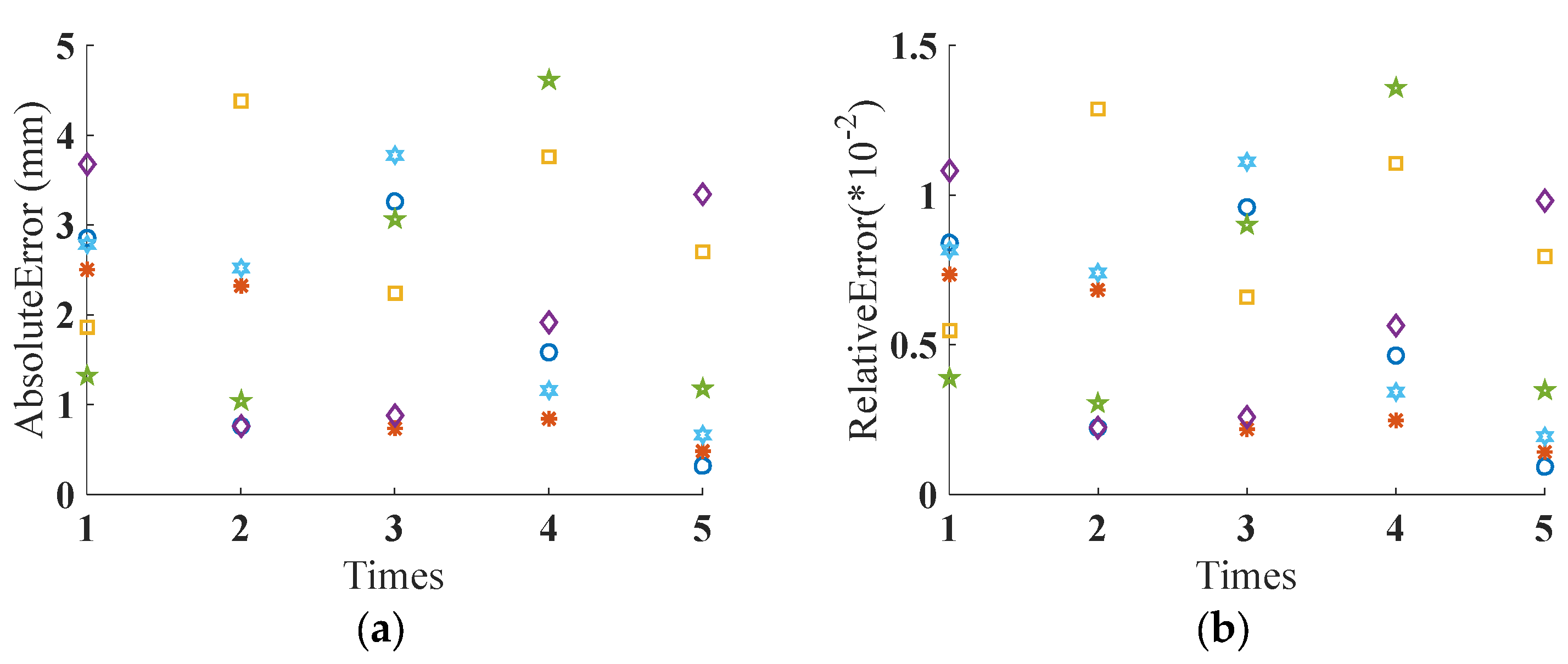
The deployable process with cable-net structure is shown in Figure 18, by which one can see that the cable-net structure is fully tensioned when the large-span ring deployable perimeter truss is fully deployed. The absence of the relaxation phenomenon is an important criterion for maintaining the accuracy of the mesh antenna surface, which also proves the accuracy and rationality of the cable-net structure design. In addition to the above, repeatability accuracy is an important indicator used to measure the reliability of the large-span ring deployable perimeter truss. Here, defining some key points as shown in Figure 12b, the distance between two adjacent key points will be used as the observation value. Then, a deployable process is carried out several times, and related data are measured, as shown in Table 4, in which the maximum absolute error is 4.38 mm and the maximum relative error is 1.288%. Overall, the absolute errors of the large-span ring deployable perimeter truss are in millimeters, and the relative errors are very small, which also means the physical prototype of the large-span ring deployable perimeter truss has high machining and assembly accuracy, as shown in Figure 19.
For existing errors, there are multiple reasons for the occurrence of errors that can be summarized as follows. First, design and assembly errors inevitably exist in the physical prototype. Second, the uneven distribution of pre-stress on the cable-net structure cannot be ignored in its impact on the large-span ring deployable perimeter truss. Third, the material stiffness of the physical prototype is limited, so the gravity environment has a certain impact on the physical prototype, which is different from the microgravity environment in space. Improving the accuracy of experimental prototypes can be approached from the following aspects. On the one hand, materials with better performance should be selected, and machining and assembly accuracy should be improved. On the other hand, the adjustment method of cable-net structure should be studied, which can be used to change the distribution and magnitude of prestress.
In short, the physical prototype testing conducted was sufficient for this stage to test the feasibility, as it provided crucial insights into the deployment motion under typical operating conditions. In fact, the on-orbit environment of the mesh reflector deployable antenna is complex, and multiple factors can affect the surface accuracy, including thermal distortion, micro-vibrations, and many others. As a future step, we plan to incorporate full-scale and environmental testing, including S-parameters and far-field radiation patterns, so professional simulations and tests on the overall performance of the antenna to acquire its characteristics are our future work, the corresponding adjusting methods for the surface accuracy will also be studied to ensure the large-span ring deployable perimeter truss performs reliably in real applications.

6. Conclusions

In this paper, a novel large-span ring deployable perimeter truss used for the mesh reflector deployable antenna is well developed, which effectively introduces the metamorphic mechanism into the self-locking design. The large-span ring deployable perimeter truss is made up of a single-mobility multi-point driving mechanism and the ring deployable metamorphic mechanism, in which the planar linkage mechanism and modular design method are widely adopted. As a result, the ring deployable metamorphic mechanism has an excellent deploy/fold ratio and scalability. When the large-span ring deployable perimeter truss is in the fully deployed state, multiple singular positions, the axes of three revolute joints are parallel and coplanar, are used to form multiple dead-center positions, which effectively change the constraint conditions. The result is that the entire mechanism has achieved mechanical self-locking, which has a significant impact on the stability and stiffening process of the antenna. The detailed mechanism design is first introduced, and the key performance is then analyzed and simulated. In addition, the cable-net structure is designed, and the connection method is discussed. Ultimately, the experiment with the large-span ring deployable perimeter truss was conducted to demonstrate its excellent deploy/fold ratio and dependable deployable performance.

Author Contributions

Writing—original draft preparation, C.G.; writing—review and editing, H.W., N.Y., J.G., F.L. and J.D. All authors have read and agreed to the published version of the manuscript.

Funding

This research was funded by the STU Scientific Research Initiation Grant (SRIG) (Grant No. NTF23019 and NTF19012), the Research Projects of the Department of Education of Guangdong Province (Grant No. 2023KTSCX317), the Shenzhen Polytechnic University Research Fund (Grant No. 6023310005K), the Provincial Natural Science Foundation of Hunan (Grant No. 2023JJ50099), and the Guangdong basic and applied basic research foundation (Grant No. 2024A1515011557).

Conflicts of Interest

The authors declare no conflicts of interest.

References

  1. Liu, Z.; Qiu, H.; Li, X.; Yang, S. Review of large spacecraft deployable membrane antenna structures. Chin. J. Mech. Eng. 2017, 30, 1447–1459. [Google Scholar] [CrossRef]
  2. Zheng, F.; Chen, M. New conceptual structure design for affordable space large deployable antenna. IEEE Trans. Antennas Propag. 2015, 63, 1351–1358. [Google Scholar] [CrossRef]
  3. Puig, L.; Barton, A.; Rando, N. A review on large deployable structures for astrophysics missions. Acta Astronaut. 2010, 67, 12–26. [Google Scholar] [CrossRef]
  4. Santiago-Prowald, J.; Baier, H. Advances in deployable structures and surfaces for large apertures in space. CEAS Space J. 2013, 5, 89–115. [Google Scholar] [CrossRef]
  5. Ma, X.; Li, T.; Ma, J.; Wang, Z.; Shi, C.; Zheng, S.; Cui, Q.; Li, X.; Liu, F.; Guo, H.; et al. Recent advances in space-deployable structures in China. Engineering 2022, 17, 207–219. [Google Scholar] [CrossRef]
  6. Thomson, M. The AstroMesh deployable reflector. IEEE Trans. Antennas Propag. 1999, 3, 1516–1519. [Google Scholar]
  7. Tserodze, S.; Medzmariashvili, E.; Klooster, C.; Muchaidze, K.C.M.; Nikoladze, M.; Chapodze, A.; Sigua, I.; Sanikidze, M. New design modifications of the supporting ring for a large deployable space reflector. CEAS Space J. 2021, 13, 175–182. [Google Scholar] [CrossRef]
  8. Qi, X.; Huang, H.; Li, B.; Deng, Z. A large ring deployable mechanism for space satellite antenna. Aerosp. Sci. Technol. 2016, 58, 498–510. [Google Scholar] [CrossRef]
  9. Qi, X.; Miao, Z.; Huang, H.; Li, B. Design and mobility analysis of large deployable mechanisms based on plane-symmetric Bricard linkage. In Proceedings of the ASME 2016 International Design Engineering Technical Conferences and Computers and Information in Engineering Conference, Charlotte, NC, USA, 21–24 August 2016. [Google Scholar]
  10. Qi, X.; Li, S.; Li, B.; Huang, H. Design of a deployable ring mechanism using V-fold bars and scissor mechanisms. In Proceedings of the 6th Annual IEEE International Conference on Cyber Technology in Automation, Control and Intelligent Systems, Chengdu, China, 19–22 June 2016. [Google Scholar]
  11. Lu, S.; Qi, X.; Hu, Y.; Li, B.; Zhang, J. Deployment dynamics of large space antenna and supporting arms. IEEE Access 2019, 7, 69922–69935. [Google Scholar] [CrossRef]
  12. Li, B.; Qi, X.; Huang, H.; Xu, W. Modeling and analysis of deployment dynamics for a novel ring mechanism. Acta Astronaut. 2016, 120, 59–74. [Google Scholar] [CrossRef]
  13. Knight, B.; Duffy, J.; Crane, C. Optimization of ring trusses for antenna structures using line geometry. J. Spacecr. Rocket. 2003, 40, 565–569. [Google Scholar] [CrossRef]
  14. Xu, Y.; Guan, F.; Xu, X.; Wang, H.; Zheng, Y. Development of a novel double-ring deployable mesh antenna. Int. J. Antennas Propag. 2012, 2012, 375463. [Google Scholar] [CrossRef]
  15. Xu, Y.; Guan, F.; Chen, J.; Zheng, Y. Structural design and static analysis of a double-ring deployable truss for mesh antennas. Acta Astronaut. 2012, 81, 545–554. [Google Scholar] [CrossRef]
  16. Feng, C.; Liu, T. A graph-theory approach to designing deployable mechanism of reflector antenna. Acta Astronaut. 2013, 87, 40–47. [Google Scholar] [CrossRef]
  17. Han, B.; Xu, Y.; Yao, J.; Zheng, D.; Li, Y.; Zhao, Y. Design and analysis of a scissors double-ring truss deployable mechanism for space antennas. Aerosp. Sci. Technol. 2019, 93, 105357. [Google Scholar] [CrossRef]
  18. Han, B.; Zhou, Y.; Zhao, Y. Kinematics and dynamics characteristics analysis of a double-ring truss deployable mechanism based on rectangular scissors unit. Eng. Struct. 2024, 307, 117900. [Google Scholar] [CrossRef]
  19. Han, B.; Xu, Y.; Yao, J.; Zheng, D.; Zhao, Y. Kinematic characteristics analysis of a double-ring truss deployable antenna mechanism. In Proceedings of the 12th International Conference of Intelligent Robotics and Applications, Shenyang, China, 8–11 August 2019. [Google Scholar]
  20. Han, B.; Xu, Y.; Yao, J.; Zheng, D.; Guo, L.; Zhao, Y. Type synthesis of deployable mechanism for ring truss antenna based on constraint-synthesis method. Chin. J. Aeronaut. 2020, 33, 2445–2460. [Google Scholar] [CrossRef]
  21. Cao, W.; Xi, S.; Ding, H.; Chen, Z. Design and kinematics of a novel double-ring truss deployable antenna mechanism. J. Mech. Des. 2021, 143, 124502. [Google Scholar] [CrossRef]
  22. He, B.; Jia, L.; Li, K.; Nie, R.; Fan, Y.; Wang, G. Deployment dynamic modeling and driving schemes for a ring-truss deployable antenna. Chin. J. Mech. Eng. 2024, 37, 79. [Google Scholar] [CrossRef]
  23. Sun, Z.; Yang, D.; Duan, B.; Kong, L.; Zhang, Y. Structural design, dynamic analysis, and verification test of a novel double-ring deployable truss for mesh antennas. Mech. Mach. Theory 2021, 165, 104416. [Google Scholar] [CrossRef]
  24. Sun, Z.; Zhang, Y.; Yang, D. Structural design, analysis, and experimental verification of an H-style deployable mechanism for large space-borne mesh antennas. Acta Astronaut. 2021, 178, 481–498. [Google Scholar] [CrossRef]
  25. Zhang, Y.; Yang, D.; Sun, Z.; Li, N.; Du, J. Winding strategy of driving cable based on dynamic analysis of deployment for deployable antennas. J. Mech. Sci. Technol. 2019, 33, 5147–5156. [Google Scholar] [CrossRef]
  26. Zhang, Y.; Yang, D.; Li, S. An integrated control and structural design approach for mesh reflector deployable space antennas. Mechatronics 2016, 35, 71–81. [Google Scholar] [CrossRef]
  27. Gao, C.; Kang, X.; Lei, H.; Xu, P.; Li, B. Design and analysis of a novel large-span two-fold deployable mechanism. Mech. Mach. Theory 2023, 186, 105352. [Google Scholar] [CrossRef]
  28. Yang, G.; Zhang, Y.; Tang, A.; Li, Y. A design approach for AstroMesh-type contoured-beam reflector antennas. IEEE Antennas Wirel. Propag. Lett. 2018, 17, 951–955. [Google Scholar] [CrossRef]
  29. Zhang, Y.; Ru, W.; Yang, G.; Li, N. Deployment analysis considering the cable-net tension effect for deployable antennas. Aerosp. Sci. Technol. 2016, 48, 193–202. [Google Scholar] [CrossRef]
  30. Du, X.; Du, J.; Bao, H.; Chen, X.; Wu, X. Dynamic analysis of the deployment for mesh reflector antennas driven with variable length cables. J. Comput. Nonlinear Dyn. 2019, 14, 111006. [Google Scholar] [CrossRef]
  31. Wu, R.; Zhang, W.; Behdinan, K. Vibration frequency analysis of beam-ring structure for circular deployable truss antenna. Int. J. Struct. Stab. Dyn. 2019, 19, 1950012. [Google Scholar] [CrossRef]
  32. Xu, Y.; Guo, J.; Guo, L.; Liu, W.; Yao, J.; Zhao, Y. Design and analysis of a truss deployable antenna mechanism based on a 3UU-3URU unit. Chin. J. Aeronaut. 2019, 32, 2743–2754. [Google Scholar] [CrossRef]
  33. Shi, C.; Guo, H.; Cheng, Y.; Liu, R.; Deng, Z. Design and multi-objective comprehensive optimization of cable-strut tensioned antenna mechanism. Acta Astronaut. 2021, 178, 406–422. [Google Scholar] [CrossRef]
  34. Dai, L.; Guan, F.; Guest, J. Structural optimization and model fabrication of a double-ring deployable antenna truss. Acta Astronaut. 2014, 94, 843–851. [Google Scholar] [CrossRef]
  35. Dai, J.; Wang, D. Orientation and workspace analysis of the multi-fingered metamorphic hand-metahand. IEEE Trans. Robot. 2009, 25, 942–947. [Google Scholar] [CrossRef]
  36. Dai, J.; Cui, L. Posture, workspace, and manipulability of the metamorphic multifingered hand with an articulated palm. ASME Trans. J. Mech. Robot. 2011, 3, 021001. [Google Scholar]
  37. Wei, G.; Dai, J.; Wang, S.; Luo, H. Kinematic analysis and prototype of a metamorphic anthropomorphic hand with a reconfigurable palm. Int. J. Humanoid Robot. 2011, 8, 459–479. [Google Scholar] [CrossRef]
  38. Gao, Z.; Wei, G.; Dai, J. Inverse kinematics and workspace analysis of the metamorphic hand. Proc. Inst. Mech. Eng. Part C-J. Eng. Mech. Eng. Sci. 2015, 229, 965–975. [Google Scholar] [CrossRef]
  39. Wang, R.; Sun, J.; Dai, J. Design analysis and type synthesis of a petal-inspired space deployable-foldable mechanism. Mech. Mach. Theory 2019, 141, 151–170. [Google Scholar] [CrossRef]
  40. Gao, C.; Huang, H.; Li, B.; Jia, G. Design of a truss-shaped deployable grasping mechanism using mobility bifurcation. Mech. Mach. Theory 2019, 139, 346–358. [Google Scholar] [CrossRef]
Figure 1. Mesh reflector deployable antenna.
Symmetry 17 01388 g001
Figure 2. Mechanism design of the basic unit: (a) regular polygon approximation techniques; (b) motion process of the basic unit.
Symmetry 17 01388 g002
Figure 3. The basic unit generated by different Pythagorean numbers: (a) Pythagorean ratio is 3:4:5; (b) Pythagorean ratio is 5:12:13.
Symmetry 17 01388 g003
Figure 4. Connection method of the adjacent deployable basic units: (a) the folded state; (b) the mid-deployed state; (c) the fully deployed state.
Symmetry 17 01388 g004
Figure 5. Ring deployable metamorphic mechanism with different sides.
Symmetry 17 01388 g005
Figure 6. Driving method of the deployable ring mechanism.
Symmetry 17 01388 g006
Figure 7. Deployment process of the large-span ring deployable perimeter truss.
Symmetry 17 01388 g007
Figure 8. Kinematic and dynamic diagram of the large-span ring deployable perimeter truss: (a) the coordinate systems in vertical view; (b) the one kinematic chain of the driving mechanism; (c) the basic unit of the ring deployable metamorphic mechanism.
Symmetry 17 01388 g008
Figure 9. Kinematic and dynamic simulation of the large-span ring deployable perimeter truss: (a) position change of point E1; (b) velocity change of point E1; (c) acceleration change of point E1; (d) deploy/fold ratio; (e) driving force τ of the large-span ring deployable perimeter truss with the constant driving velocity 2 mm/s; (f) velocity of the point E1 with the constant driving acceleration 1 mm/s2.
Symmetry 17 01388 g009
Figure 10. Two main types of cable-net structure: (a) triangular cable-net structure; (b) cable-arch structure.
Symmetry 17 01388 g010
Figure 11. Geometric model of the cable-arch structure: (a) cable-arch structure for the spherical surface antenna; (b) polygon approximation method for reflector.
Symmetry 17 01388 g011
Figure 12. Prestress analysis of central cable segment and cable-net model: (a) central cable segment; (b) cable-net model with six groups of cable-arch structures.
Symmetry 17 01388 g012
Figure 13. Connection method of cable-net structure: (a) connection of cable segment in the same node; (b) connection with the large-span ring deployable perimeter-truss.
Symmetry 17 01388 g013
Figure 14. Physical prototype and mesh structure: (a) the large-span ring deployable perimeter truss; (b) cable-net structure.
Symmetry 17 01388 g014
Figure 15. Control software used for the large-span ring deployable perimeter truss.
Symmetry 17 01388 g015
Figure 16. Control system and deployable experimental platform.
Symmetry 17 01388 g016
Figure 17. Movement sequence verification of the large-span ring deployable perimeter truss: (a) movement sequence verification in the horizontal state; (b) movement sequence verification in the spatial state.
Symmetry 17 01388 g017
Figure 18. Deployable process verification with cable-net structure: (a) deployable process verification in the horizontal state; (b) deployable process verification in the spatial state.
Symmetry 17 01388 g018
Figure 19. Error distribution of the large-span ring deployable perimeter truss in deployment motion process: (a) absolute error; (b) relative error.
Symmetry 17 01388 g019
Table 1. The scale parameters of the physical prototype.
Linka1, a2b1, b2c1, c2d1, d2e1, e2g1g2
Length170 mm170 mm85 mm340 mm340 mm340 mm20 mm
Table 2. The scale parameters of the cable-net structure.
CableC1C2C3C4C5C6C7C8
Length12 mm12 mm12 mm12 mm12 mm12 mm12 mm12 mm
Table 3. The key driving parameters of the servo motor.
ItemRated TorquePole PairsMaximum SpeedReduction RatioSensor
Value128 mNm810,000 rpm26:1Mile 2048 cpt
Table 4. Errors of the distance between adjacent key points.
Adjacent Key PointsTimesA1A2A2A3A3A4A4A5A5A6A6A1
Absolute errors (mm)First time2.86 mm2.50 mm1.86 mm3.68 mm1.32 mm2.78 mm
Second time0.76 mm2.32 mm4.38 mm0.76 mm1.04 mm2.52 mm
Third time3.26 mm0.74 mm2.24 mm0.88 mm3.06 mm3.78 mm
Forth time1.58 mm0.84 mm3.76 mm1.92 mm4.62 mm1.16 mm
Fifth time0.32 mm0.48 mm2.70 mm3.34 mm1.18 mm0.66 mm
Relative errors (%)First time0.841%0.735%0.547%1.082%0.388%0.818%
Second time0.224%0.682%1.288%0.224%0.306%0.741%
Third time0.959%0.218%0.659%0.259%0.900%1.112%
Forth time0.465%0.247%1.106%0.565%1.359%0.241%
Fifth time0.094%0.141%0.794%0.982%0.347%0.194%
Disclaimer/Publisher’s Note: The statements, opinions and data contained in all publications are solely those of the individual author(s) and contributor(s) and not of MDPI and/or the editor(s). MDPI and/or the editor(s) disclaim responsibility for any injury to people or property resulting from any ideas, methods, instructions or products referred to in the content.