Article

PSO-Driven Scalable Dual-Adaptive PV Array Reconfiguration Under Partial Shading

by
Özgür Karaduman
1,* and
Koray Şener Parlak
2
1
Department of Software Engineering, Faculty of Engineering, Fırat University, 23119 Elazığ, Türkiye
2
Department of Electronics Technology, Vocational School of Technical Sciences, Fırat University, 23119 Elazığ, Türkiye
*
Author to whom correspondence should be addressed.
Symmetry 2025, 17(8), 1365; https://doi.org/10.3390/sym17081365
Submission received: 23 July 2025 / Revised: 9 August 2025 / Accepted: 13 August 2025 / Published: 21 August 2025

Abstract

Partial shading conditions cause current mismatches between series-connected panels in photovoltaic (PV) arrays, significantly reducing power efficiency. To mitigate this limitation, reconfiguration methods based on dynamically changing the electrical connections within the PV array have been proposed. In recent years, adaptive and dual-adaptive PV connection structures, which particularly balance the line currents and aim to restore current symmetry under irregular shading conditions, have gained prominence due to their notable efficiency improvements. The dual nature of these structures inherently supports this symmetry by enabling balanced reconfigurations on both sides of the array. However, the dual-adaptive structure expands the solution space due to the exponential growth of the connection combinations with the increasing number of lines, and this makes real-time optimization difficult. In fact, this structure has been optimized with genetic algorithm (GA) before; however, the convergence time of GA exceeds acceptable limits in large arrays. In this study, a Particle Swarm Optimization (PSO) algorithm is applied to solve the dual-adaptive PV array reconfiguration problem. Particle Swarm Optimization (PSO) is a metaheuristic algorithm that utilizes swarm intelligence to efficiently explore large solution spaces. PSO’s fast convergence capability and low computational cost enable real-time applications by enabling optimization in acceptable times even for larger PV arrays. Simulation results reveal that PSO successfully manages the exponential growth in the solution space and significantly increases the real-time applicability of the reconfiguration process by effectively increasing the efficiency. In this respect, PSO is considered a powerful and practical solution for reconfiguration problems in large-scale PV arrays.

1. Introduction

1.1. Motivation

Photovoltaic (PV) systems are increasingly gaining prominence in the energy sector due to their role in sustainable energy generation [1,2]. However, the efficiency of these systems is highly sensitive to solar irradiance levels [3,4]. Partial shading conditions cause current mismatches in PV arrays, resulting in power losses [5]. To address this problem, dynamic reconfiguration methods have been proposed, which adapt panel interconnections in real time [2,6,7,8]. To overcome efficiency losses caused by partial shading, researchers have developed two types of reconfiguration methods: static and dynamic [9]. Conventional static reconfiguration approaches operate either by physically relocating the modules depending on their exposure to shading [10], or by mathematically reordering the module indices using row-index-based techniques to redistribute the shading effect [11]. Among these methods, Sudoku-based reconfiguration, which rearranges panel indices using matrix-based patterns to distribute shading effects more evenly, has been widely adopted [12,13]. The absence of switching hardware makes these approaches less complicated. However, the physical relocation of panels within the array requires additional labor [10]. On the other hand, dynamic reconfiguration methods adjust specific parameters within the array using algorithms to reorganize the panel connections [14,15]. Adaptive PV array structures enable dynamic reassignment of specific panels, increasing connection flexibility while also introducing additional complexity into the system topology [16,17]. In these methods, a subset of the panels within the PV array is adaptively selected, and the connection to the remaining panels is established in real time according to a specific algorithm, thereby performing the reconfiguration. The use of adaptive connection structures has been a significant step toward reducing efficiency losses by better aligning the line currents [18,19]. This balancing effect inherently contributes to electrical symmetry within the PV array, particularly in dual-adaptive architectures designed to maintain uniform current distribution under varying shading conditions. These flexible structures, however, significantly enlarge the solution space, especially in large-scale systems. This makes it difficult to determine the optimal connection and results in scalability issues in large PV arrays [20]. In this context, it has become critical not only to develop flexible connection structures but also to ensure fast and efficient optimization within the expanded solution space [21,22]. Notably, the dual-adaptive structure inherently introduces a form of symmetry in the array configuration, as it dynamically balances two interrelated sets of panel connections to achieve optimized current alignment.
This study aims to address the scalability problem caused by the exponential growth of connection combinations in dual-adaptive PV array structures and to enable real-time reconfiguration by employing the Particle Swarm Optimization (PSO) algorithm.

1.2. Problem Statement

This study focuses on reducing the power efficiency degradation caused by row current mismatches under partial shading. Such conditions have led to the development of dynamic panel reconfiguration strategies. Later extensions such as single-adaptive and dual-adaptive structures offered enhanced performance by increasing the flexibility of connections. Specifically, in single-adaptive structures, the flexible connection of certain panels has led to enhanced efficiency under partial shading conditions.
Subsequently, dual-adaptive structures have been proposed, expanding connection flexibility by increasing the number of adaptive panels, and thus achieving higher power efficiency under partial shading scenarios. However, the flexibility provided by dual-adaptive structures, combined with the increasing number of rows, leads to an exponential growth of the solution space.
The structural differences between single-adaptive and dual-adaptive PV array configurations are shown in Figure 1. In single-adaptive PV structures, let the set of fixed panels be denoted as F = [F1, F2, …, Fm], where m represents the number of rows. Correspondingly, the adaptive panel set is given as A = [A1, A2, …, Am]. The total number of unique connection configurations between fixed and adaptive panels can be calculated using the permutation notation P 2 m m , assuming binary connection states.
For example, when m = 3, each fixed panel can connect to one or more of the 2 m = 8 possible adaptive panel combinations, resulting in a total of P 8 3 = 336 distinct connection patterns.
In dual-adaptive configurations, the structure includes two independent adaptive parts per row, effectively doubling the number of adaptive panels to 2m. Thus, the adaptive panel set becomes A = [A1, A2, …, A2m], while the fixed panel set remains the same. In this case, the number of potential binary states per row becomes 2m, and the total number of overall fixed–adaptive connection patterns is calculated as P 2 2 m m .
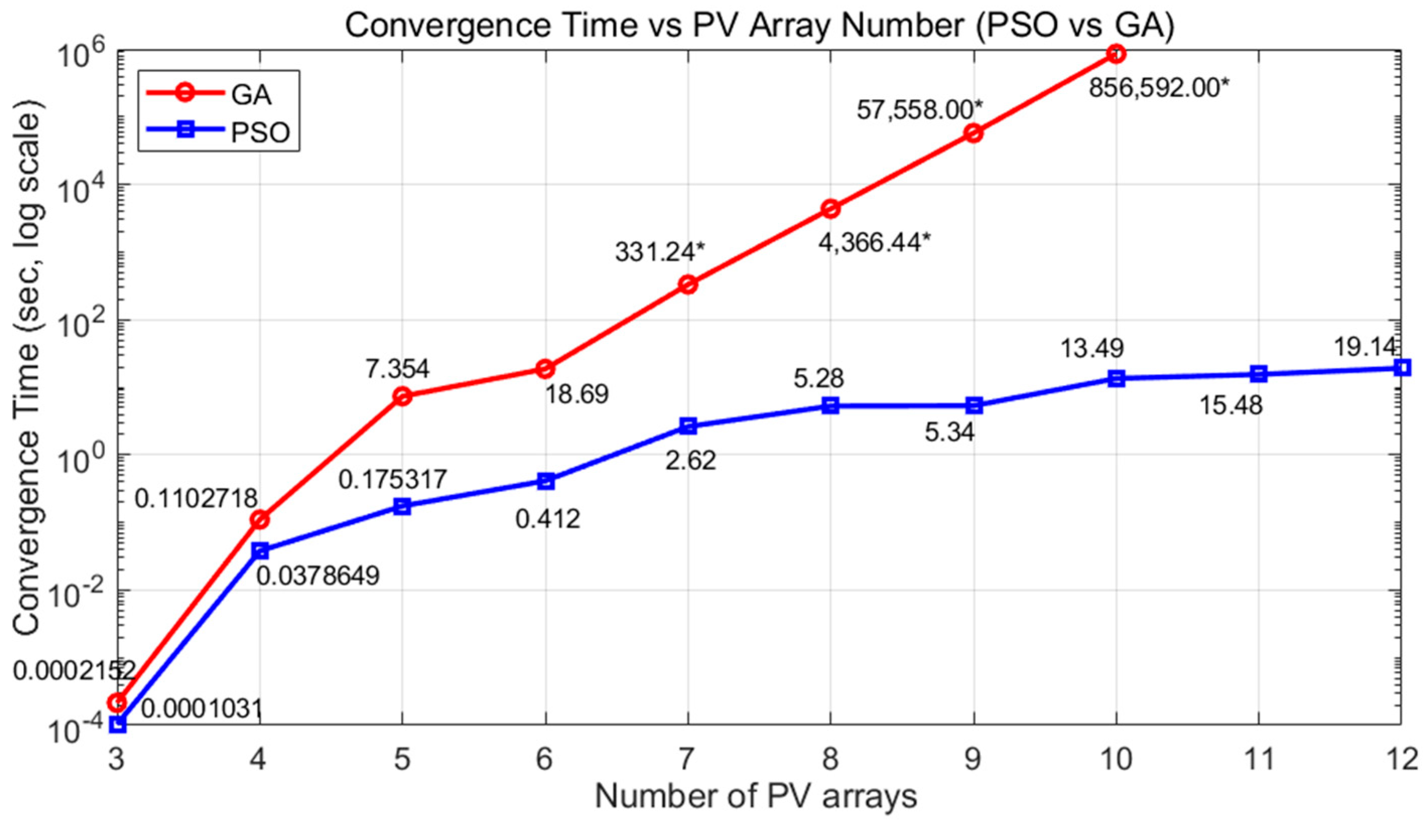
As an illustrative case, for m = 3, we obtain: P 2 2 × 3 3 = P 2 6 3 = P 64 3 = 249,984. Similarly, when m = 4, the number of configurations is: P 2 2 × 4 4 = P 2 8 4 = P 256 4 = 4,195,023,360. When the number of rows increases to five, this number reaches 1.11 × 10 15 , for six rows, it becomes 4.71 × 10 21 , for seven rows, it reaches approximately 3.17 × 10 29 , and for twelve rows, the number skyrockets to 4.97 × 10 77 . In other words, for a 12-row PV array, the optimization process involves searching for the most efficient configuration among 4.97 × 10 77 possible connection states. Although expressions such as 4.97 × 1077 clearly illustrate the explosive growth in the solution space, their practical implications are even more significant. In real-world scenarios, exploring such a massive number of configurations leads to unacceptable computational costs. This can be observed in Figure 2, where the convergence time of the GA algorithm increases dramatically with the number of PV arrays. For instance, while GA requires only 0.11 s for three-row PV arrays, it takes more than ~850,000 s for 10 arrays. In contrast, PSO maintains significantly lower convergence times for the same cases. This sharp increase confirms that the exponential growth in configuration space translates directly into an exponential rise in computational burden. Therefore, the use of fast-converging metaheuristics such as PSO is not only beneficial but essential for practical and scalable PV array reconfiguration. This exponential growth highlights the dramatic increase in the solution space as the number of rows grows, making real-time optimization highly challenging for large-scale PV systems. Therefore, the exponentially growing solution space makes it extremely challenging to find the optimal connection within acceptable timeframes, particularly in large-scale PV arrays, resulting in a serious scalability problem. Figure 2 presents a logarithmic-scale comparison illustrating the impact of increasing the number of rows on the solution space, alongside the convergence behavior of GA and PSO optimization algorithms under these conditions.
As shown in Figure 2, although the GA method reaches a solution within acceptable timeframes in small-scale arrays, its convergence time grows exponentially in relation to the PV array row count. For arrays with seven rows and beyond, GA becomes inadequate for real-time usage. In contrast, the PSO algorithm achieves acceptable convergence times even in arrays with 12 rows or more, positioning itself as a strong alternative capable of meeting the real-time reconfiguration requirements of dual-adaptive structures.
In this context, the primary problem addressed in this study is the inability to determine suitable connection configurations within acceptable timeframes due to the rapid expansion of the solution space when the number of PV array rows increases in dual-adaptive systems. This issue poses a critical barrier to real-time reconfiguration applications. Therefore, it has become inevitable to investigate faster-converging and computationally efficient heuristic methods capable of effectively exploring such large solution spaces.

1.3. Related Works

Partial shading conditions in PV arrays cause mismatches between row currents, significantly reducing power efficiency. Various methods have been developed in the literature to address this issue.
Early studies focused on passive techniques such as fixed connection patterns and bypass diodes [5,19]. However, these methods proved insufficient in eliminating current mismatches under dynamic shading conditions [2,7]. To overcome these limitations and reduce efficiency losses, reconfiguration approaches have been introduced. These approaches involve modifying the electrical connections among the panels in the array based on irradiance conditions to balance the current [2,6,7,23]. First-generation reconfiguration methods involved manual connection changes. Although these approaches provided efficiency improvements under certain circumstances, they lacked the capability to respond quickly and flexibly to varying environmental conditions [5,19,24]. All methods that automatically reorganize the panel connections in PV arrays according to changing environmental conditions within a specific algorithmic framework are defined as dynamic reconfiguration methods [6]. It is evident that performing full reconfiguration of all panels in a PV array is not a realistic approach for real-time applications due to circuit topology and processing costs. To address these shortcomings, adaptive reconfiguration structures have been developed. In adaptive systems, the connections of specific panels are made flexible and dynamically altered based on irradiance conditions, optimizing the proximity of the row currents to each other [7,18,25]. Initially, single-adaptive structures were proposed, where certain panels have adaptive connection features while others remain fixed. Single-adaptive structures have demonstrated better performance compared to fixed connection systems and have particularly improved efficiency in small and medium-scale PV arrays [26]. However, to further reduce current mismatches by increasing the number of adaptive panels and expanding connection flexibility, dual-adaptive structures have been introduced. Dual-adaptive systems expand the connection space by increasing the number of adaptive panels, thereby enhancing the likelihood of achieving higher power efficiency under partial shading with more optimal connection configurations. In dual-adaptive structures, both intra-row panel connections and inter-row connections are made flexible, enabling further reduction of shading-induced power losses. Nevertheless, with the growth in the number of rows, the exponential growth of connection combinations has led to a scalability problem, making it significantly more difficult to determine suitable connections in real time, especially in large-scale PV arrays [20].
Due to the rapid increase in the number of connection combinations in dynamic reconfiguration methods, the use of optimization algorithms has become inevitable. Metaheuristic techniques such as GA, PSO, and Artificial Bee Colony (ABC) have been widely utilized because of their ability to identify suitable connection configurations in large solution spaces [22,23,27,28,29]. Heuristic algorithms have recently become a powerful tool for solving complex optimization problems. Heuristic algorithms have different characteristics and significant advantages compared to traditional optimization techniques such as gradient descent [30]. In particular, for large PV arrays with a high number of rows, such optimization techniques play a critical role in solving reconfiguration problems. In this context, previous studies have employed GA-based methods for optimizing the connection configurations of dual-adaptive structures [20]. These studies demonstrated that GA can enhance power efficiency; however, the exponential expansion of the solution space with increasing row numbers prolongs the optimization time, limiting real-time applications and scalability in large PV arrays. Consequently, this expansion of the solution space and the extended convergence time have highlighted the need for alternative metaheuristic algorithms with faster convergence capabilities.
Although previous studies have addressed adaptive structures and heuristic optimization methods separately, to the best of our knowledge, there is no existing work in the literature focusing on optimizing dual-adaptive PV arrays using rapidly converging algorithms such as PSO. This study aims to fill this gap by demonstrating the advantages of PSO in dual-adaptive structures, thereby developing a real-time and scalable reconfiguration process. In this way, both power efficiency is improved, and a scalable, dynamic, and real-time decision-making approach is proposed for reconfiguration in large PV arrays.

1.4. Proposed Approach

In this study, the dual-adaptive PV array reconfiguration problem is addressed. In the dual-adaptive structure, while some of the panels in the array maintain fixed connections, specific panels are equipped with adaptive connection capabilities. These adaptive panels, through flexible connection structures, are dynamically switched to the rows containing the fixed panels. This mechanism reduces current mismatches between the rows, making it an effective approach for enhancing power efficiency under partial shading conditions.
The suitability of any given connection configuration is evaluated based on the proximity of the row currents to each other. For this purpose, the Current Variation Index (CVI) is utilized [26]. Additionally, the CVI offers a practical advantage in real-time applications due to its low computational complexity and fast evaluability, which allows rapid assessment of many candidate configurations during optimization. The CVI is defined as the difference between the maximum and minimum short-circuit currents (Isc) among the rows after the adaptive panels are matched to the fixed panels. A lower CVI value indicates more balanced row currents, and the optimal connection configuration is determined by minimizing this value.
In dual-adaptive structures, the solution space rapidly expands due to the exponential growth of connection combinations, particularly as the number of rows increases. This leads to a scalability problem that makes it difficult to identify an appropriate connection configuration within acceptable timeframes. The expanded solution space poses a significant challenge for real-time reconfiguration applications in large PV arrays. In this study, the PSO algorithm is employed to efficiently explore the solution space and ensure real-time applicability. In the PSO algorithm, each particle represents a bit sequence corresponding to the panel connection configuration. Particle positions are iteratively updated to search for the optimal connection within the solution space. The fitness of each particle is determined by the CVI value corresponding to the specific connection configuration. The proposed method leverages the fast convergence capability and low computational cost of PSO to overcome the scalability problem that arises with increasing row numbers in dual-adaptive PV arrays. The primary objective is to enable a real-time applicable reconfiguration process in large PV arrays while maximizing power efficiency.

1.5. Contributions

The main contributions of this study are summarized below:
  • PSO-Based Optimization Approach for Dual-Adaptive PV Arrays: This study introduces the application of PSO to the reconfiguration problem of dual-adaptive PV arrays for the first time, enabling fast and efficient optimization in an exponentially expanding solution space. It also marks the initial demonstration that GA becomes infeasible for large-scale dual-adaptive configurations due to excessive convergence times, and proposes a PSO-based alternative that meets real-time applicability requirements.
  • Fast Convergence and Efficient Optimization in Large Solution Spaces with PSO: Against the exponentially expanding connection possibilities as the number of rows increases, PSO’s particle-based and accelerated convergence capabilities enable efficient optimization in larger solution spaces.
  • Enhanced Adaptive Panel-Fixed Panel Matching Efficiency: In dual-adaptive structures, the expanded matching space is more effectively explored through PSO’s flexible solution search mechanism. This leads to more balanced row currents across various shading scenarios, unlocking the potential for higher power efficiency.
  • Scalable and Real-Time Reconfiguration Time for Large PV Arrays: With the PSO-based optimization approach, the reconfiguration time for large-scale PV arrays remains at real-time applicable levels, even in the exponentially growing solution space caused by an increasing number of rows in dual-adaptive PV arrays. This enhances the practical applicability of reconfiguration methods in large PV systems and allows faster adaptation to dynamic shading conditions.
  • Adaptability of Metaheuristic Approaches to Solution Space Expansion: This study highlights the potential of fast-converging metaheuristic algorithms like PSO to provide scalable reconfiguration solutions for large-scale PV arrays, addressing the solution space expansion inherent in dual-adaptive structures.

1.6. Paper Organization

The subsequent sections of this paper are structured as follows. In Section 2, the structure of PV arrays is detailed, and the core logic of the proposed dual-adaptive PV system is introduced along with its system block diagram. Section 2.1 describes the configuration of the adaptive and fixed panel segments, while Section 2.2 presents the reconfiguration mechanism, highlighting the use of metaheuristic algorithms for dynamic control. The exponential increase of the solution space in relation to the number of panel rows and its associated computational challenges are analyzed in Section 2.3, with illustrative examples provided in Table 1. Section 2.4 outlines the chromosome modeling approach for PSO-based optimization and explains how adaptive-fixed matching configurations are encoded into bit strings. In Section 2.5, the algorithm developed for eliminating invalid configurations is introduced to ensure valid reconfiguration patterns throughout the optimization process. Finally, Section 2.6 defines the CVI, which is used as the fitness function to evaluate and rank each configuration. The results obtained from the simulations are reported in Section 3. Section 3.1 outlines the configuration scenarios and simulation hardware setup, while Section 3.2 reports the fundamental optimization outcomes for each scenario. A comparative scalability analysis between PSO and GA is provided in Section 3.3, covering PV systems with three to twelve rows. Section 4 presents the Discussions, focusing on convergence speed, optimization accuracy, and the real-time applicability of the PSO-based reconfiguration approach. Finally, Section 5 provides the Conclusions, summarizing the findings of this study and outlining possible future research directions, including hybrid reconfiguration strategies, real-time deployment architectures, and integration with AI-based predictive models.

2. Materials and Methods

In this study, a dual-adaptive PV array reconfiguration system is addressed. The PV array used in the study is structured as an m × n matrix, where the first and last columns of each row consist of panels with adaptive connections (adaptive part), while the remaining columns contain panels with fixed connections (fixed part). The adaptive panels can be connected to appropriate points of the rows via a switching matrix circuit. This structure enables the dynamic modification of the connection patterns of adaptive panels, allowing current matching with the fixed panels [26]. Current sensors placed on a row-wise basis continuously measure the short-circuit currents of the panels and provide input data for the optimization process. To determine the optimal connection pattern, the PSO algorithm is employed. The suitability of each connection combination is evaluated using the CVI, which is based on the current differences among the rows. This section describes the fundamental components of the proposed dual-adaptive PV array system, including the matching principle of adaptive and fixed panels, the switching matrix for dynamic connection changes, and the evaluation of power output.

2.1. Dual-Adaptive PV Panel Architecture

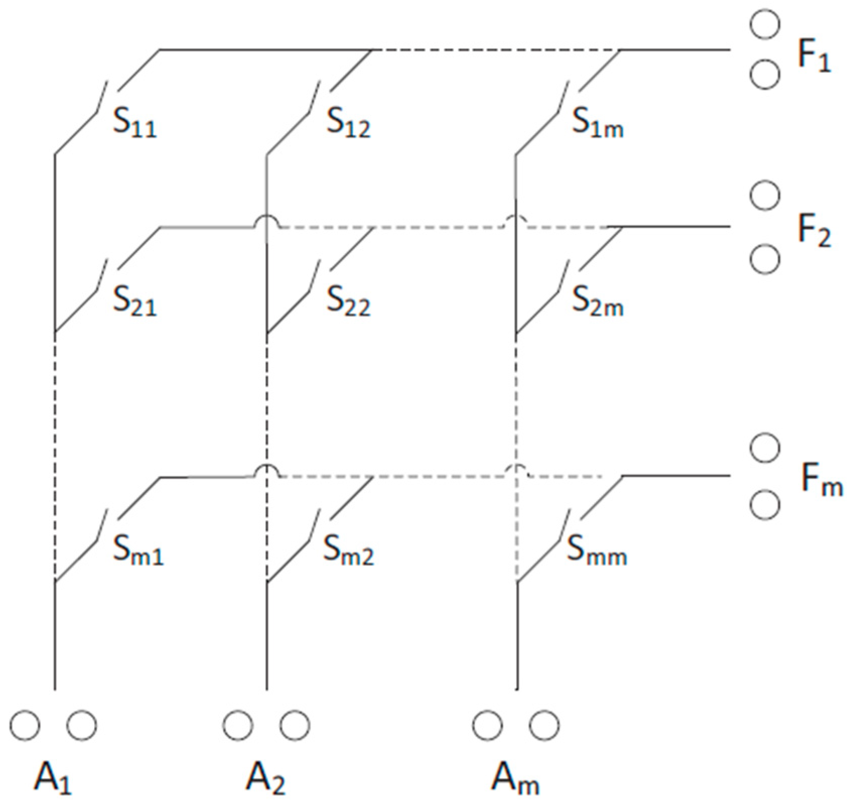
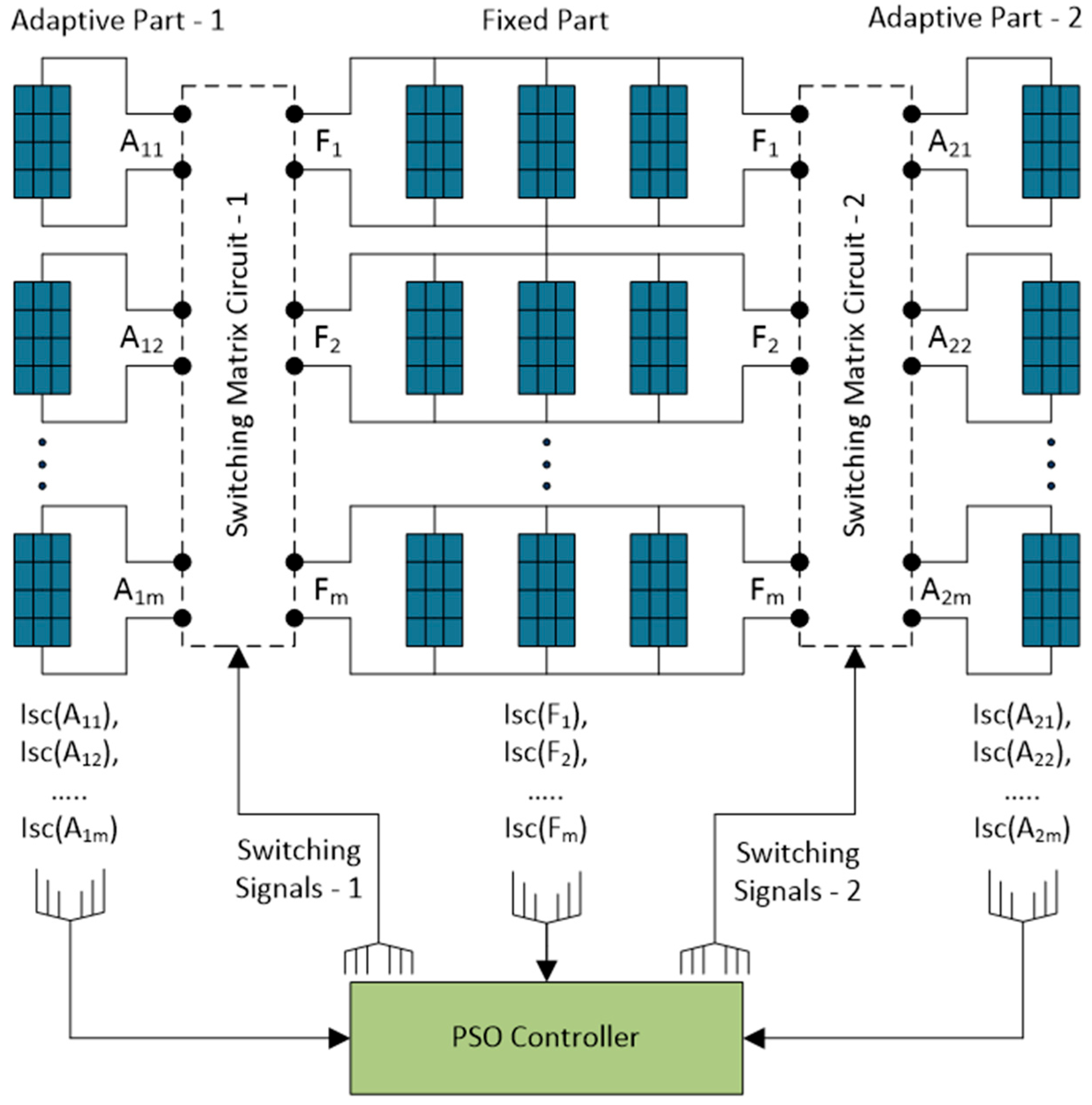
The PV array architecture proposed in this study is based on a dual-adaptive connection system. In this configuration, an m × n PV array with a Total Cross-Tied (TCT) connection scheme is considered. The first and last columns of the panels in each row are designed as adaptive panels (adaptive part), while the remaining columns are structured as fixed panels. The adaptive panels can be connected to different rows in accordance with the current levels of the fixed panels in each row. These adaptive connections are managed via a switching matrix circuit, allowing the panels to be dynamically routed to the appropriate rows. The switching matrix circuit structure [26] is given in Figure 3.
In this architecture, the short-circuit currents of each row are continuously monitored through row-based sensors, and this data is used to determine the connection patterns of the adaptive panels. The current data obtained from the sensors is incorporated into the CVI, which evaluates the suitability of each connection configuration during the reconfiguration process. Circles denote switchable connection terminals between adaptive panels and fixed rows.
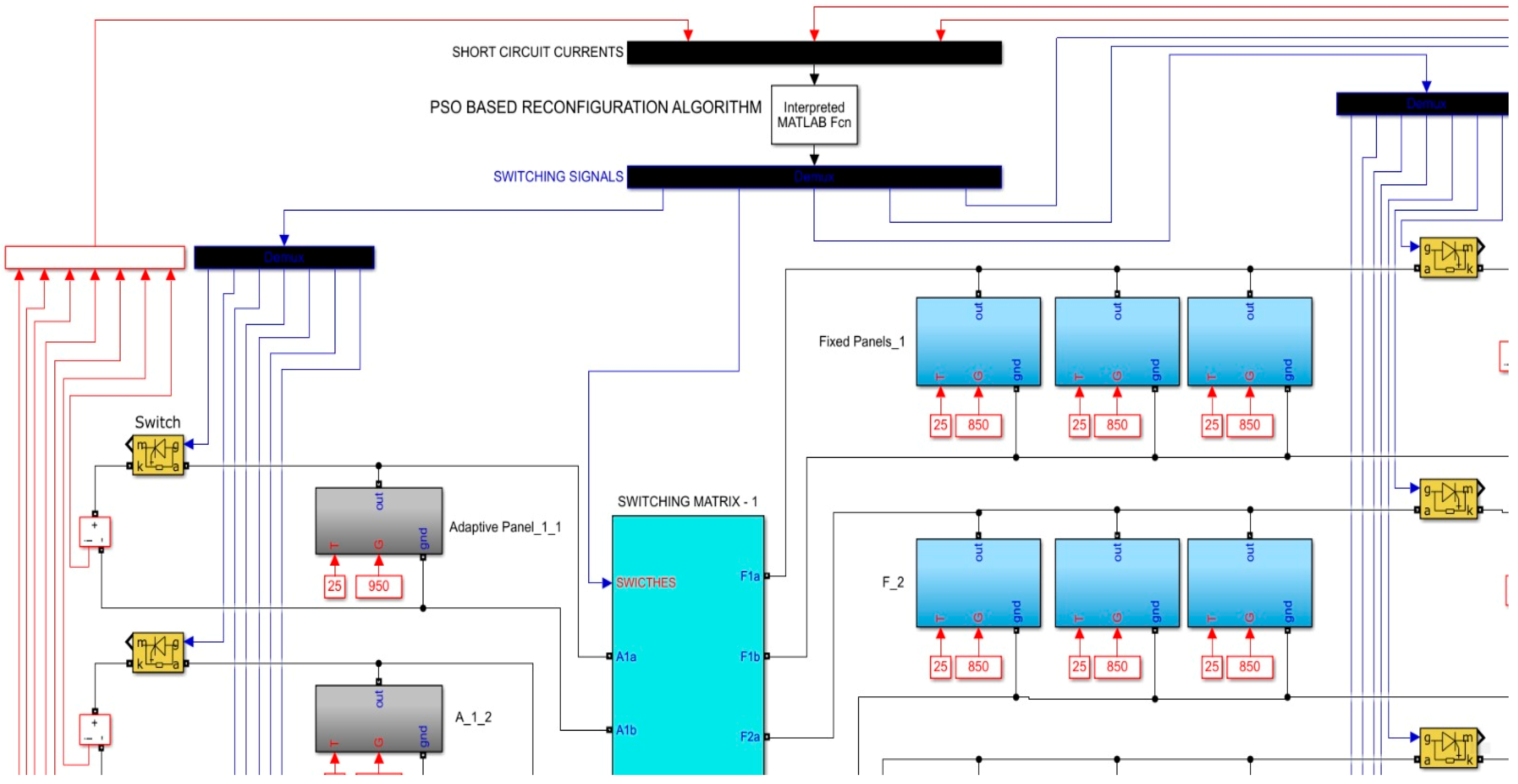
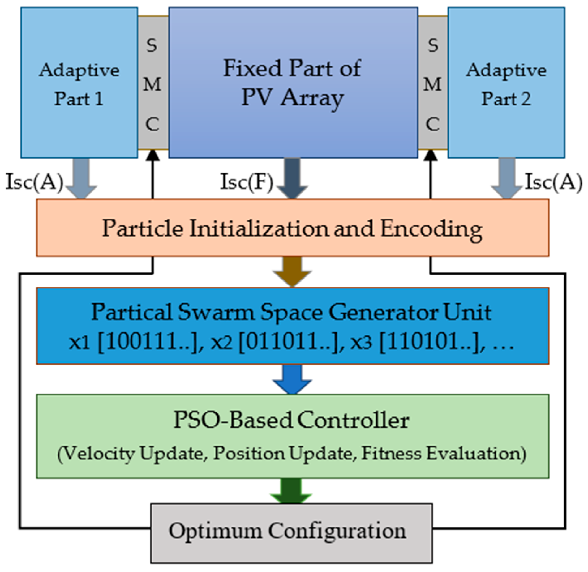
The CVI metric is based on the assessment of current differences between rows. As the mismatch between row currents decreases, the power output of the array increases correspondingly. With its flexible connection capability, the dual-adaptive structure aims to minimize current mismatches under partial shading conditions, thereby improving the overall power output. The proposed architecture, controlled by a PSO-based controller, is illustrated in Figure 4.
However, the ability of adaptive panels to be redirected to different rows leads to an exponential increase in connection possibilities. This makes it particularly challenging to determine the optimal connection configuration in arrays with a large number of rows. Therefore, an optimization algorithm is required in the process of determining the optimal connection combination.

2.2. Reconfiguration Process of PV Arrays Involving Adaptive Parts

In the dual-adaptive PV array structure, the panel connection configuration is continuously updated to minimize current mismatches within the rows. In this context, the connection status of the adaptive panels is determined based on the ability to operate in alignment with the current levels of the fixed panels.
During the reconfiguration process, each adaptive panel is assigned to a specific row in a way that matches the current levels of the fixed panels within that row. Once the panel connections are set, the current of each row is determined, and all panels in the same row are forced to operate at the current level of the panel with the lowest current. This step is necessary due to the current matching requirement of series-connected panels.
The total power output corresponding to the given connection configuration is calculated as follows:
  • The current of each row is determined (according to the minimum current in the row).
  • The voltages of all panels in each row are summed.
  • The total power output of the array is obtained by multiplying the current of each row by the sum of the row voltages.
The power calculation in this study assumes ideal voltage summation within each row, ignoring the effects of voltage mismatch and non-linear IV characteristics among the series-connected panels. While this assumption simplifies the estimation process and aligns with common practices in preliminary optimization studies, it may lead to slight deviations in practical implementations due to the non-linear and temperature-dependent nature of PV panels. Future work may integrate more detailed PV models, including partial IV curve simulations, to refine power estimation accuracy.
The suitability of each connection configuration is evaluated using a metric called the CVI. The CVI is based on assessing the differences between the row currents. The CVI calculation process consists of the following steps:
  • The short-circuit currents of each row are measured using sensors.
  • For each connection configuration, the row currents are determined.
  • The differences between the row currents are calculated, and the minimum of these differences is taken as the CVI value.
Figure 5 illustrates the overall workflow of the proposed reconfiguration process for dual-adaptive PV arrays. In this process, the connections between adaptive and fixed panels are restructured according to predefined rules to improve the system’s power efficiency. As shown in the figure, the system consists of three main stages: Particle Initialization and Encoding, Particle Swarm Space Generator Unit, and the PSO-based controller. In the first stage, all possible connection combinations of the adaptive panels are represented as bit strings, where each possible connection configuration is modeled as a particle. Subsequently, a predefined number of initial configurations are randomly generated within the particle swarm and included in the optimization process. The system takes as input the short-circuit current values from the fixed panels (F) and adaptive panels (A), denoted as Isc(F) and Isc(A). These current values are processed in the Particle Initialization and Encoding stage to determine the connection possibilities, and the corresponding combinations are generated in the Particle Swarm Space Generator Unit.
The PSO algorithm iteratively updates the velocity and position of each particle to achieve the optimal connection configuration. The PSO-based controller module evaluates the fitness of each particle using a fitness function based on the CVI. The CVI is calculated for each connection configuration to identify the pattern that minimizes the imbalance among the row currents, thereby determining the optimal connection setup. At the end of the optimization process, the best connection configuration is selected and sent to the Switching Matrix Controller (SMC). The SMC physically applies the optimal configuration by adjusting the matching between adaptive and fixed panels.
This structure enables the system to dynamically adapt to continuously changing shading conditions, balancing the row currents and increasing the efficiency of the PV array. The proposed design allows for efficient exploration of the large solution space in dual-adaptive PV arrays and enhances the real-time reconfiguration capability of the system. The process shown in the figure represents a dynamic optimization mechanism, where the particles reach the optimal connection configuration through iterative updates of their velocities and positions, ultimately improving system efficiency.

2.3. Particle Initialization and Encoding

2.3.1. Binary Representation of All Feasible Connection Combinations Between Fixed and Adaptive Panels

In dual-adaptive PV array structures, the diversity of possible connection combinations between fixed and adaptive panels defines the system’s solution space and directly influences the optimization process. Under partial shading conditions, the connections between fixed and adaptive panels are restructured to reduce current mismatches between rows, thereby improving power efficiency. The dual-adaptive structure, in particular, allows each set of fixed panels to establish connections with two adaptive panel groups within the same row. This flexibility significantly increases the number of possible connection combinations, enabling the system to achieve more efficient configurations. In the PSO algorithm, these connections are represented by bit strings, where each particle corresponds to a specific connection configuration within the solution space. The initialization of particle positions and their binary encoding is the first step of the optimization process and is critical for the effective operation of the algorithm.
In this study, the matching of each fixed panel with one or more adaptive panels is represented as a bit string, where the presence of a connection is indicated by “1” (connected) and the absence of a connection is indicated by “0” (not connected). In this way, each PV array is represented as a specific particle and included in the optimization process of the PSO algorithm. In an m-row PV array, each row consists of m fixed panels represented by F = {F1, F2, …, Fm}, along with 2m adaptive panels represented by A = {A1, A2, …, A2m}. Each fixed panel can be connected to any subset of the adaptive panels in its corresponding row. Since the connection or disconnection states of the panels are represented in binary format, the total number of possible connection states for each row is 22m. However, the total number of different connection combinations between all fixed and adaptive panels in the array is calculated using permutation. In the dual-adaptive structure, the general formula for the connection possibilities between fixed and adaptive panels is expressed as P 2 2 m m , which denotes the number of combinations when selecting m rows from 22m possible connection states. For example, when m = 3, there are 2 × 3 = 6 adaptive panels in each row, and the number of possible combinations is P 2 6 3 = P 64 3 = 249,984. Similarly, for m = 4, the calculation is P 256 4 = 4,195,023,360.
Table 1 illustrates how the number of all possible connection combinations in single-adaptive and dual-adaptive PV array structures increases exponentially with the row count. The sharpness of this exponential growth becomes particularly evident from the 7th row onward. For instance, in a dual-adaptive PV array with just 7 rows, the number of possible connection combinations reaches a massive 3.165 × 1029. When the number of rows increases to 10, this number becomes approximately 1.606 × 1060, and for 12 rows, it reaches a 78-digit number. Although this study focuses directly on dual-adaptive structures, the values presented in the table clearly demonstrate that as the number of rows increases, the solution space rapidly expands, making the optimization process increasingly critical in large arrays. This exponential growth highlights that exhaustive search of all possibilities is practically infeasible, especially in real-time applications, reinforcing the necessity of metaheuristic optimization algorithms.
The total number of connection combinations is calculated using the permutation expression P 2 2 m m , which denotes the number of ways to assign m rows from 22m possible connection states in the dual-adaptive structure, where m is the number of rows in the PV-array. This reflects the exponential growth of the solution space as the number of rows increases.
As the number of rows grows, the exponential increase in connection combinations between fixed and adaptive panels significantly enlarges the solution space. In such cases, exhaustive search methods, such as the scanning algorithm proposed in [26], which evaluates all possible configurations one by one, become impractical for large PV arrays, especially in real-time scenarios. The need to rapidly determine a new connection configuration to adapt to changing irradiance conditions requires solutions within highly limited time frames. In situations where scanning all possibilities could take hours or even days, this approach is no longer feasible. Therefore, metaheuristic algorithms that can reach near-optimal solutions without exploring the entire solution space stand out as more effective methods for reconfiguration problems. In this study, the PSO algorithm is employed, which updates particle positions continuously and converges rapidly toward the global optimum solution. PSO is particularly advantageous in large solution spaces due to its faster convergence with fewer parameter adjustments and its simple structure. In dual-adaptive PV arrays, as the number of rows increases and the number of possibilities grows exponentially, exhaustive search methods become impractical, whereas PSO enables the identification of suitable connection configurations in real time, even in large-scale arrays. Each fixed panel’s connection status with the adaptive panels is represented by binary bit strings to allow processing by optimization algorithms. For each fixed panel, the connection or disconnection status with the adaptive panels is indicated by “1” and “0”. For example, in an array where m = 3, the fixed panels are F1, F2, F3, and the adaptive panels are A1, A2, …, A6. A corresponding connection representation can be formed accordingly.

2.3.2. Representation of Connections with Bit Strings

The matching status of each fixed panel with specific adaptive panels is represented using bit strings. For example, in a PV array where m = 3, the connection representation is constructed as shown in Table 2:
The bit strings are concatenated from top to bottom to form a single particle. For example, 101001 010000 000110 corresponds to an 18-bit particle (6 + 6 + 6 = 18-bits). In this way, each possible connection combination is represented by a specific bit string and becomes a particle optimized by PSO. During the optimization process, particles are updated through velocity and position adjustments, allowing them to explore different locations in the solution space to determine the optimal connection configuration.
This representation enables the PSO algorithm to perform systematic and rapid searches across the large solution space. In large-scale dual-adaptive PV arrays, finding the optimal connection configuration with PSO becomes critical due to the exponential growth of the solution space.

2.3.3. Exponential Growth of the Solution Space in Dual-Adaptive Structures

The dual-adaptive PV array structure allows each fixed panel to establish connections with multiple adaptive panels within its row, represented as binary bit strings. As the number of rows (F) increases, both the number of adaptive panels (A) and the bit length of each particle grow proportionally. This results in a rapid, exponential expansion of the solution space, making exhaustive search infeasible in real-time applications.
Table 3 illustrates this exponential growth by showing how the total number of possible connection configurations increases with the number of fixed rows. For each row, the number of possible assignments is calculated as 2A, where A = 2 × F. Since each fixed row makes its assignment independently, the total number of configurations is (2A)F. Accordingly, the particle length in the PSO algorithm is equal to A × F bits, encoding all possible binary combinations for the fixed-adaptive panel connections.
As can be observed, even with a moderate number of rows (e.g., F = 6), the total number of possible configurations exceeds 1021. This exponential growth underscores the necessity of metaheuristic algorithms like PSO, which can efficiently search such large spaces to find near-optimal configurations without evaluating every possibility.

2.4. Particle Swarm Space Generator Unit

The generation of a suitable initial population is a critical step for the effective operation of the PSO algorithm. The Particle Swarm Space Generator Unit is designed to generate particles representing connection configurations in dual-adaptive PV arrays, check their validity, and include them in the optimization process. This module creates the initial population of PSO using the binary-encoded connection configurations defined in the Particle Initialization and Encoding stage. However, the objective is not only to generate random particles but also to select valid connection configurations to accelerate the PSO convergence process. For the PSO algorithm, N initial particles are generated, denoted as x = {x1, x2, …, xN}. Each particle xi is encoded as a binary bit string representing the connection configuration of the PV array, where xi = [b1, b2, …, bL]. Here, L = 2m2 denotes the bit length of all possible connection configurations in the dual-adaptive PV array. Each bit bj ∈ {0, 1} indicates whether a specific fixed panel is connected to a particular adaptive panel. For each particle, velocity vectors v = {v1, v2, …, vN} are initialized randomly, where vi = [v1, v2, …, vL] and each vj ∈ ℝ represents the velocity of the corresponding bit.
At the initialization stage, each particle is randomly assigned a connection configuration, and the physical validity of each configuration is checked. Invalid connections are eliminated, and only feasible connection combinations are included in the optimization process. The particles generated in this module serve as the core components of the PSO algorithm, where velocity and position updates are performed in the PSO-based controller to determine the optimal connection configuration.

2.5. Particle Validity Check and Elimination of Invalid Configurations

In dual-adaptive PV arrays, the number of adaptive panels is set to twice the number of rows containing fixed panels. As illustrated in Figure 5, this structure leads to an exponential increase in the number of possible connection combinations due to the double-row arrangement of adaptive panels. Although each fixed panel can potentially be connected to any of the adaptive panels, some connection combinations are physically invalid. For example, a configuration where the same adaptive panel is connected to multiple fixed panels simultaneously, or where an adaptive panel is not connected to any fixed panel, is considered invalid. Therefore, the connection configuration represented by each particle must be checked for physical feasibility. Since a large portion of the solution space consists of invalid configurations, eliminating such particles is critical to reducing computational overhead and increasing algorithmic efficiency. In single-adaptive structures, the number of valid connection configurations for a PV array with m rows is mm, whereas in dual-adaptive structures, this value is m2m. For example, when m = 3, the single-adaptive case results in 33 = 27 valid connections out of a total of 336 possible combinations. In the dual-adaptive case, the number of valid connections is 32×3 = 729 out of 249,984 total combinations. This highlights the challenge of identifying valid connections in the solution space as one of the core problems of the optimization process.
The elimination of invalid connections is performed using the check_validity() function, which verifies the correctness of each particle’s connection pattern. This function analyzes the bit string of each particle, checking the connection status of the adaptive panels corresponding to each fixed panel. It ensures that no adaptive panel is connected to more than one fixed panel and that each adaptive panel is connected to at least one fixed panel. If a connection is found to be invalid, the corresponding particle is eliminated from the population. Below are examples of invalid and valid matches.
Below are examples of invalid matches. In the first example, the combination is invalid because A2 part is matched with more than one F part. In the second example, this combination is also invalid because A6 part is not matched with any F part.
F1 part   F2 part   F3 part
[__A2__A4__A6] [__A2__ __ __ __] [A1__A3__A5__] (Invalid)
F1 part   F2 part   F3 part
[A1__ __ __A5__] [__A2A3__ __ __] [__ __ __A4__ __] (Invalid)
Below are examples of valid matches. In both examples, all adaptive parts are matched with one F part, and no adaptive part is matched with more than one F part. As long as this rule is followed, it is not against the rules for any fixed part to remain unmatched.
F1 part    F2 part   F3 part
[__ __A3__A5__] [__A2__A4__ __] [A1__ __ __ __A6] (Valid)
F1 part   F2 part   F3 part
[A1__A3__ __A6] [__ __ __ __ __ __] [__A2__A4A5__] (Valid)
The pseudo-code of the check_validity() function, which determines whether each connection combination represented by a particle is valid or not, is provided as in Algorithm 1.
Algorithm 1. check_validity()
Input:  x: particle, N: adaptive panel array length,
ROW: fixed panel array length
Output: valid (1: valid, 0: invalid)
1:  set fixed_arrayzero_array(N), k ← 1
2:  for i = 1 to N×ROW
3:    fixed_array (k) ← fixed_array (k)+ x(i)
4:    kk + 1
5:    if k > N then k ← 1 endif
6:  endfor
7:  set product ← 1
8:  for t = 1 to N
9:    product = product*fixed_array(t)
10:  endfor
11:  if product = 1 then valid ← 1
12:  else valid ← 0 endif
13:  return valid

2.6. PSO-Controller: Optimization of the Connection Configuration

Metaheuristic algorithms serve as versatile search methods aimed at identifying optimal or near-optimal solutions within large and complex search spaces. These approaches are critically important in discrete and combinatorial optimization problems, such as the dual-adaptive PV array reconfiguration problem, where the number of connection combinations grows exponentially and conventional search methods become inadequate. Metaheuristic algorithms employ various mechanisms such as randomness, memory usage, and swarm behavior to avoid local minima and guide the search toward global optimum.
In this study, PSO is used to optimize the connection configuration between fixed and adaptive panels in the dual-adaptive PV array structure. PSO is an optimization algorithm inspired by biological swarm behavior, and it updates the positions of particles in the solution space to approach the optimum solution. Each particle represents a candidate solution, where the position is expressed as a binary bit string indicating the panel connections in the dual-adaptive PV array. In the PSO algorithm, the positions and velocities of the particles are iteratively updated to search for the most suitable configuration in the solution space.

2.6.1. Particle Representation and Position-Velocity Updates

In the PSO approach, each particle is denoted as xi, and this particle is represented by a binary bit string indicating the panel connections in the dual-adaptive PV array, as expressed in Equation (1):
x i = x i 1 ,   x i 2 , ,   x i 2 m 2 ,     x i j { 0 , 1 }
Here, m represents the number of rows, and 2m2 denotes the bit string length corresponding to all possible panel connections in the dual-adaptive structure. In this notation, xi denotes the entire particle as a solution vector, while xij refers to the j-th bit of the particle. In addition to the positions, each particle has a velocity vector defined as in Equation (2):
v i = v i 1 ,   v i 2 , ,   v i 2 m 2 ,     v i j
In this representation, vi denotes the entire velocity vector of the i-th particle, while vij refers to the j-th velocity component. Particle velocities and positions are updated in each iteration. The velocity update is performed according to Equation (3):
v i j t + 1 = w . v i j t + c 1 r 1 p b e s t i j x i j t + c 2 r 2 g b e s t j x i j t
where w is the inertia weight coefficient, c1 and c2 are cognitive and social coefficients, r1 and r2 are random numbers uniformly distributed in [0, 1], pbestij is the best position component found by particle i, and gbestj is the global best position component in the swarm.
Since a binary PSO structure is employed, the position update is performed probabilistically. The update probability for each bit is calculated using the sigmoid transfer function as in Equation (4):
s i j t + 1 = 1 1 + e v i j ( t + 1 )
Here, s i j t + 1 is the probability value computed by the sigmoid function based on the updated velocity. Instead of applying a fixed threshold (e.g., 0.5), a probabilistic sampling approach is adopted, where a random number uniformly drawn from [0, 1] is compared against s i j t + 1 . This ensures stochastic exploration of the solution space. The position update is then performed according to Equation (5):
x i j t + 1 = 1 ,   i f   r a n d < s i j ( t + 1 ) 0 ,   o t h e r w i s e  
Since the binary version of PSO is used, the position update differs from classical continuous PSO by relying on probabilistic updates. The sigmoid function maps the velocity value into a probability between 0 and 1, and the new position is determined based on this probability, resulting in either a 0 or 1 value [31,32,33].

2.6.2. PSO-Based Controller Module

This module corresponds to the “Particle Swarm Controller” in the system block diagram. It manages the PSO process, including particle velocity and position updates, and ultimately determines the optimal connection configuration. Due to the large size of the solution space, fast-converging algorithms such as PSO play a critical role in enabling scalable reconfiguration for dual-adaptive PV arrays.
Particles are initialized with random positions and velocities. The fitness of each particle is evaluated using the CVI based on its connection configuration represented by the bit string. The configuration with the lowest CVI value is accepted as the optimal connection pattern. The general workflow of the PSO algorithm is summarized in the following pseudo-code. Algorithm 2 outlines the PSO-based controller designed to perform the adaptive reconfiguration of a hybrid photovoltaic (PV) array system composed of both fixed and adaptive panels. In this pseudo-code, the controller initializes the solution space by generating binary-coded candidate configurations for adaptive panel connections, alongside velocity vectors for each particle. The required inputs include the array information for both panel types, the swarm size, iteration limits, and the key PSO parameters: inertia weight (w), cognitive factor (c1), and social factor (c2).
The optimization process seeks the configuration that minimizes the CVI, which evaluates the balance of current distribution among the PV array rows. The CVI is computed by assessing the difference between the highest and lowest current contributions after adaptive adjustments under partial shading conditions.
Algorithm 2. PSO-Based Controller
Inputs: fixed_panel_array, adaptive_panel_array, numParticles, maxiteration, w, c1, c2
Output: optimum_configuration, best_particle, best_fitness (CVI ← max-min)
1:  N ← length(adaptive_panel_array)
2:  ROW ← length(fixed_panel_array)
3:  particleLengthNxROWx2
4:  foreach particle i = 1 to numParticles
//particleLength-dimensional cartesian product of binary values
5:     x i ← randomly initialize from {0, 1}^particleLength
//particleLength-dimensional real-valued vector space
6:     v i ← randomly initialize from ℝ^particleLength
7:     p b e s t i x i
8:     f i t n e s s i evaluate_fitness ( x i , N, ROW, adaptive_panel_array, fixed_panel_array)
9:  endforeach
10:  gbest ← argmax( f i t n e s s i )
11:  for iter = 1 to maxiteration
12:    for particle i = 1 to numParticles
13:     foreach dimension d in particleLength
14:        v i [d] ← w × v i [d] +      //update velocity
15:          c1 × rand() × ( p b e s t i [d] − x i [d]) +
16:          c2 × rand() × (gbest[d] − x i [d])
17:       s ← 1/(1 + exp(- v i [d]))     //sigmoid
18:       if rand() < s then  x i [d] ← 1     //update position
19:       else x i [d] ← 0 endif
20:     endforeach
21:     if check_validity( x i , N, ROW) then
22:       f i t n e s s i evaluate_fitness( x i , N, ROW, adaptive_panel_array, fixed_panel_array)
23:      if  f i t n e s s i > fitness( p b e s t i ) then p b e s t i x i  endif
24:      if  f i t n e s s i > fitness(gbest) then gbest x i  endif
25:     endif
26:    endfor
27:  endfor
28:  optimum_configuration ← gbest
29:  best_particle ← gbest
30:  best_fitness ← fitness(gbest)
31:  return optimum_configuration, best_particle, CVI ← best_fitness
At initialization, the problem size is determined based on the number of adaptive rows (N) and the number of fixed columns (ROW), resulting in a particle length of N × ROW × 2. This length represents the binary-encoded switching configuration of each particle. The position of each particle (xi) is randomly initialized in the binary Cartesian space {0, 1}L while the velocity vectors (vi) are sampled from the real-valued space ℝL. Each particle is then evaluated using the evaluate_fitness() function, where the CVI corresponding to the current configuration is calculated. In each iteration, particles update their velocities and positions according to the classical PSO update rule, based on the difference between their personal best positions (pbest) and the global best position (gbest). A sigmoid function with stochastic random components is used to probabilistically determine the binary state of each dimension of the particle. Only configurations validated by the check_validity() function are re-evaluated and compared against previous best solutions. The optimization procedure continues until the predefined iteration limit is met. At the end of the process, the particle corresponding to the best solution, characterized by the lowest CVI, is selected as the optimal configuration, and its fitness score is reported as the final output Through this structure, the algorithm converges to a valid and efficient reconfiguration of the PV array under dynamic environmental conditions.

2.7. Current Variation Index (CVI)

The fitness value used in the optimization of dual-adaptive PV arrays is determined by the Current Variation Index (CVI), which measures the current imbalance in each row. The CVI is defined as the difference between the maximum and minimum current contributions of the fixed panels. Minimizing this difference reduces current mismatches between the rows and enhances the overall power efficiency of the array. In the proposed method, the CVI is computed for each particle’s connection configuration by updating the fixed panel currents to include contributions from the adaptive panels. This process results in the cumulative current vector (FA), and the CVI is evaluated accordingly. A smaller CVI reflects improved current balance, leading to enhanced PV array performance. In this context, the fitness of each particle is calculated using the evaluate_fitness() function, as described in Algorithm 3. This function evaluates the PV panel connection configuration represented by the particle’s bit string and returns the corresponding CVI value.
Algorithm 3. evaluate_fitness(): CVI calculation
Input: particle, A: Adaptive array, F: Fixed array,
N: length of A, ROW: length of F,
Output: fitness_value (CVI)
1:  set k ← 0, Fk ← 0, n ← 1
2:  initialize FA ← zero_array(ROW)
3:  for i = 1 to NxROW
4:   kk + 1
5:   FkFk+ particle(i)xA(k)
6:   if k equal N then
7:    FA(n) ← Fk + F(n)
8:    k ← 0, Fk ← 0, nn + 1
9:   endif
10:  endfor
11:  rowSum ← sum(FA), smallest ← min(FA)
12:  largest ← max(FA), fitness ← (largest − smallest)//best fitness
13:  return CVIfitness
In the reconfiguration process, the CVI value of a new configuration is calculated based on the matching of adaptive panels, represented by vector A, with fixed panels, represented by vector F. In a PV array with three rows (m = 3), the number of possible matchings between adaptive and fixed panels is given by P 2 2 m m = P 64 3 = 249,984 combinations. Therefore, among all valid configurations within this solution space, the one with the lowest CVI value is considered the optimal configuration, and its CVI value is assigned as the fitness score. Each fixed part (F) is matched with adaptive parts in the following format:
F1 part   F2 part    F3 part
[A1 A2 A3 A4 A5 A6] [A1 A2 A3 A4 A5 A6] [A1 A2 A3 A4 A5 A6]
6-bit  +   6-bit  +  6-bit
The rule for valid matching is defined as follows: Each fixed panel (F) may be matched with some, all, or none of the adaptive panels. However, the same adaptive panel cannot be connected to more than one fixed panel simultaneously, and every adaptive panel must be matched with exactly one fixed panel. Therefore, since each F has the possibility to be connected to all adaptive parts, the entire matching of fixed panels to adaptive panels in a dual-adaptive reconfiguration structure with three rows is represented by an 18-bit binary string (6 + 6 + 6 = 18 bits). In the PSO-based optimization process, this bit string is referred to as a particle. Each particle, consisting of bits with values of 1 or 0, represents a possible F-A matching configuration within the full solution space. A value of 1 indicates that the corresponding adaptive panel is matched with the related fixed panel, while 0 denotes no connection. For example, in a configuration such as F1 → A1 A3 A6, F2 → A2 A4, and F3 → A5, the bit string representation is as follows:
F1 part   F2 part   F3 part
[A1 A2 A3 A4 A5 A6] [A1 A2 A3 A4 A5 A6] [A1 A2 A3 A4 A5 A6]
1 0 1 0 0 1  0 1 0 1 0 0 0 0 0 0 1 0
The bit string (i.e., particle) representing this matching is: 1 0 1 0 0 1 0 1 0 1 0 0 0 0 0 0 1 0. In a PV array where the irradiance values of the adaptive panels are given as A = [1.51, 1.51, 1.7, 3.41, 3.79, 3.79], and the irradiance values of the fixed panels are F = [7, 9.06, 10.04], the CVI value corresponding to the configuration represented by this particle can be calculated using Algorithm 3. The manual calculation proceeds as follows: for each fixed panel, the irradiance values of the matched adaptive panels are summed together with the irradiance of the fixed panel itself. Then, the CVI is obtained by taking the difference between the maximum and minimum of these aggregated values.
In the given example, F1 is matched with A1, A3, and A6, yielding a total irradiance of F1 + A1 + A3 + A6 = 7 + 1.51 + 1.7 + 3.79 = 14. F2 is matched with A2 and A4, resulting in 9.06 + 1.51 + 3.41 = 13.98. F3 is matched with only A5, giving 10.04 + 3.79 = 13.83. The CVI is then computed as the difference between the highest and lowest of these values: 14 − 13.83 = 0.17. Thus, the CVI of the particle representing this specific configuration is obtained as 0.17.
By calculating the CVI for all valid configurations in the solution space, the configuration with the lowest CVI value is selected as the optimal reconfiguration. This allows maximizing power efficiency under partial shading conditions by minimizing current mismatch across the array. The step-by-step procedure for CVI calculation is also provided in Algorithm 3.

3. Simulation Results

3.1. Structural Properties of Simulation Scenarios and Hardware Environment

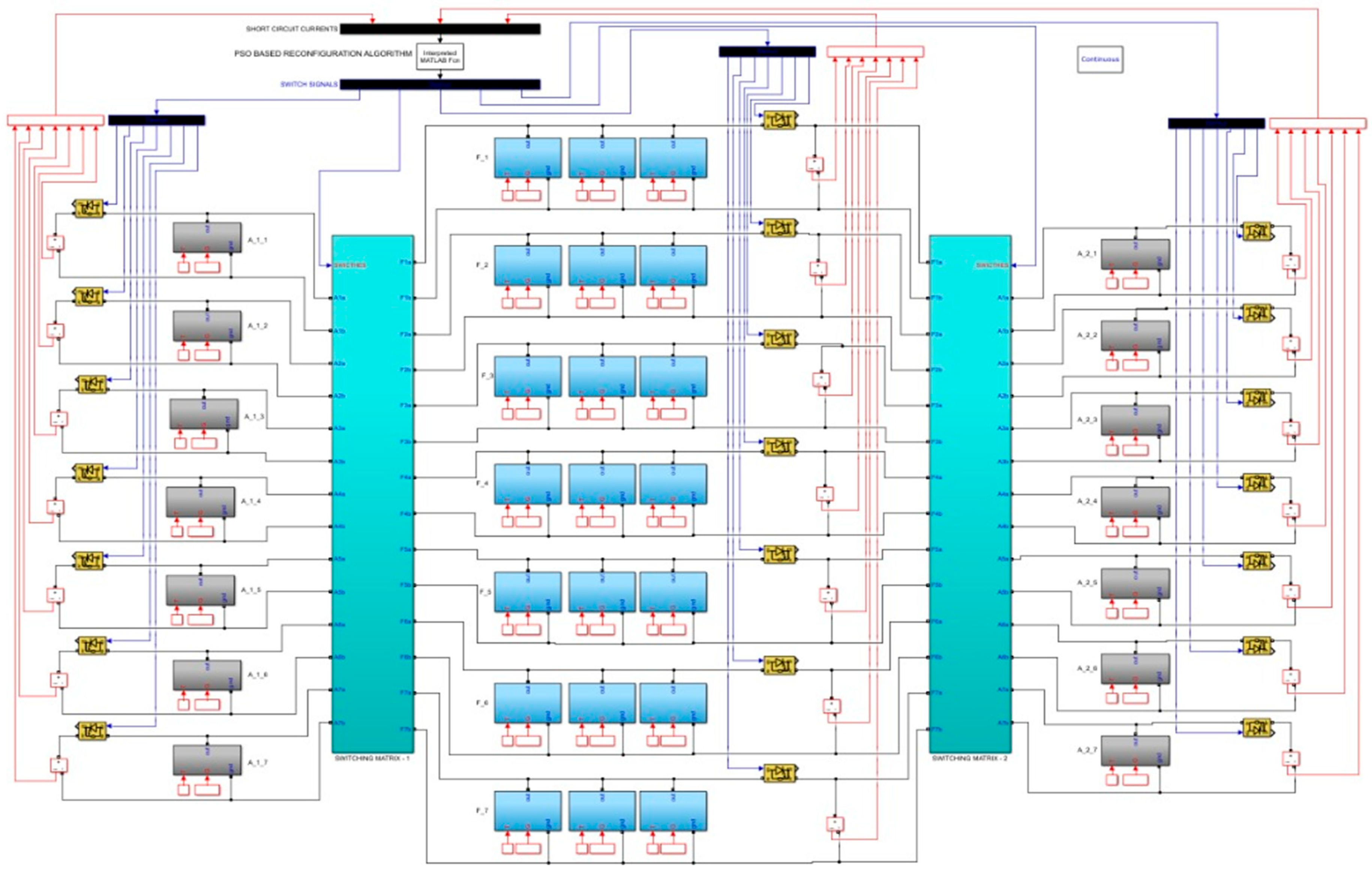
The simulations have been executed on a system powered by an Intel Core i9 14th Generation processor, 96 GB of RAM, and the Windows. MATLAB 2023b and Simulink have been utilized as the primary development and execution environment. The dual-adaptive PV array model was implemented with predefined solar modules and a dynamically controlled switching matrix to emulate partial shading conditions. The reconfiguration logic was optimized using the Particle Swarm Optimization (PSO) algorithm. No physical hardware or real-time testbed was used, and all performance metrics, such as total generated power, Current Variability Index (CVI), and convergence time, were obtained from simulation runs. The complete model structure and simulation blocks are detailed in the Appendix A.
PSO-based dual-adaptive PV array reconfiguration model has been tested through simulations performed on systems with varying scales, from three-row to twelve-row configurations. The specific adaptive and fixed panel setups employed in each scenario are detailed in Table 4.
The scenarios presented in Table 3 have been used as the foundational structure throughout all experimental processes in this study. These scenarios include various configurations of adaptive and fixed PV panel arrays, ranging from three-row systems to twelve-row systems. They are designed to observe the effects of system size and complexity on the scalability, convergence time, and optimization performance of the reconfiguration algorithms. In each scenario, the adaptive panels are modeled with different short-circuit current (Isc) values to emulate the effects of partial shading. This modeling creates variable generation profiles, each representing a specific irradiance intensity. The adaptive panels are positioned at both ends of the array, simulating the system’s reactive and flexible components. In contrast, the fixed panels are located in the central block of the structure, defined with higher and stable Isc values to act as the system’s reference component. This structure allows each scenario to simultaneously include both flexible sections, which require adaptation under shading conditions, and stable reference power sources within the same system.

3.2. Core Simulation Results of PSO-Based Reconfiguration for Dual-Adaptive PV Systems

The sensitivity of reconfiguration performance to different PSO parameters has been analyzed using experimental results from Scenario 5, which represents a seven-row PV array structure. The fundamental findings of the selected example configurations are summarized in Table 5.
Table 5 presents selected key results from a total of 144 different PSO experiments conducted within Scenario 5, which involves seven-row PV array configurations. In all experiments, four primary PSO parameters, population size, inertia weight (w), cognitive coefficient (c1), and social coefficient (c2), were varied, and reconfiguration optimization was performed for each combination. The table reports the CVI (Best Fitness) values obtained for each parameter combination, the corresponding convergence times (in seconds), and the resulting adaptive-fixed PV array configurations.
The CVI value serves as the primary performance metric for reconfiguration, where lower CVI values indicate better optimization performance. In this context, the best result was achieved in Experiment 138, where the CVI value was 0.69. In this experiment, the population size was set to 100, with w = 0.9, c1 = 2, and c2 = 1.8. The convergence time was approximately 2.62 s, reflecting successful optimization in terms of both quality and computational efficiency.
The “Configuration” column in the table explicitly indicates the mapping of fixed (F) and adaptive (A) panels in each row. For example, the notation “F4 → A1 A6 A7” specifies that the fourth fixed row is matched with adaptive panels A1, A6, and A7. Thus, each experimental record provides a comprehensive view of both the parameter settings and the resulting physical panel arrangement.
In Table 6, the best fitness values (CVI) and their corresponding configurations obtained using the PSO algorithm are presented in detail for all configuration scenarios, ranging from three-row to twelve-row structures.
Table 6 summarizes the best CVI value obtained from 144 different PSO experiments for each scenario, along with the corresponding PV array configuration. As observed, the CVI value generally increases with scenario complexity (i.e., the number of rows). This trend reflects the increasing difficulty of finding an optimal solution in larger configuration spaces. For example, in Scenario 1 with three rows, the CVI value was 0.17, while in Scenario 10 with twelve rows, it reached 3.96. The resulting configurations demonstrate the effective matching of fixed and adaptive panels, visualizing the system’s adaptive control capability.

3.3. Scalability Comparison of PSO and GA Based on Reconfiguration Times in Large-Scale Dual-Adaptive PV Arrays

Table 7 presents a comparative analysis of the scalability performance of GA and PSO in the reconfiguration of dual-adaptive PV arrays, focusing on their convergence times across different numbers of rows.
The results indicate that the GA algorithm exhibits certain scalability limitations. While the convergence time remains acceptable for real-time applications up to six rows, it reaches 331.24 s for seven rows and 4366.44 s for eight rows. For configurations with nine rows or more, the solution time becomes practically unmeasurable. This outcome demonstrates that the time complexity of GA increases exponentially with problem size, making it unsuitable for dynamic reconfiguration under rapidly changing conditions. It should be noted that these findings were obtained on a specific hardware environment with defined processor and memory capacities. On more powerful systems, GA might still produce acceptable results for configurations with seven or eight rows. However, this does not eliminate the fundamental scalability issue of GA. In contrast, the PSO algorithm provides significantly more manageable convergence times, maintaining stable performance even as the system size increases. Especially for configurations up to twelve rows, PSO achieves convergence within a matter of seconds, effectively meeting the requirements of real-time reconfiguration. The core of this success lies in the interactive movement of PSO particles through the solution space, guided by continuously updated individual and global knowledge. This mechanism makes the search process more balanced, dynamic, and rapid, preventing the exponential growth of time complexity. Experimental trends also reveal that PSO is capable of providing solutions within approximately 60 s even for configurations with up to twenty rows. This indicates that PSO not only maximizes power efficiency under partial shading conditions but also offers a scalable and practical solution for high-dimensional PV array structures.

3.4. Power Efficiency Improvement After PSO-Based Reconfiguration for High-Row PV Arrays

Table 8 analyzes the impact of reconfiguration on actual power efficiency, particularly for PV array scenarios with a high number of rows. The table clearly demonstrates the extent to which the PSO-optimized panel arrangements produce higher energy output compared to the initial total power before reconfiguration.
As shown in Table 8, the PSO-based reconfiguration process has resulted in significant power gains across all scenarios. In PV array structures with seven to twelve rows, the power improvement rates range from 33% to 51%, achieved within acceptable convergence times. This demonstrates that the system can be effectively reconfigured for real-world applications. The highest efficiency gain, 51.04%, was obtained for the seven-row configuration. Although the exact values vary depending on the irradiation levels used in the simulations, the results indicate that substantial improvements can be achieved in all scenarios.
These observations also provide insight into how the proposed method scales as system complexity increases. Notably, even at the seven-row configuration, considered a critical threshold where traditional GA algorithms begin to struggle, PSO successfully delivers over 40% efficiency improvement in just 2.6 s. As the array size expands to 10 or 12 rows, the convergence time increases as expected due to the exponential growth in solution space. Despite this, PSO consistently maintains efficiency gains above 33%. Moreover, the relatively low CVI values across scenarios reflect the algorithm’s ability to find high-quality configurations efficiently, even under more demanding conditions.
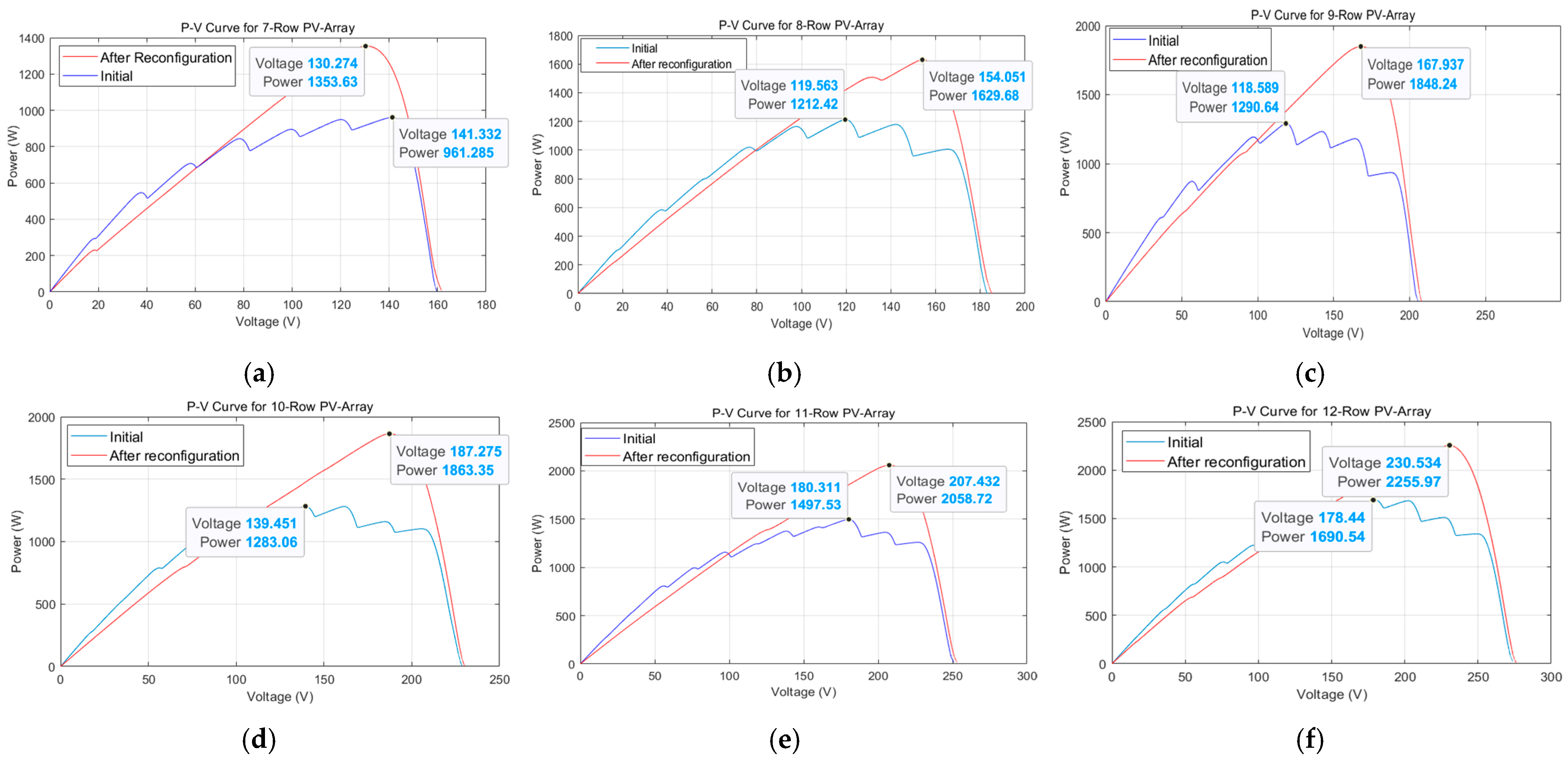
The power efficiency improvements presented in Table 8 are visualized in Figure 6 through power–voltage (P-V) curves. For each structure, the comparison between the initial state and the new configuration obtained after PSO optimization clearly illustrates the performance gains. In the curves, the red line, which represents the reconfigured system, consistently exhibits higher power output compared to the blue line corresponding to the initial state. These results strongly support the effectiveness of the proposed approach in realistic operational environments.
Figure 6 shows the P-V curves for Scenarios 5 to 10, illustrating the change in maximum power point (MPP) after applying PSO-based reconfiguration to PV arrays with seven to twelve rows. In Scenario 5 (Figure 6a), the initial MPP was 961.28 W, which increased to 1353.63 W after reconfiguration, yielding a 40.74% efficiency gain. In Scenario 6 (Figure 6b), the MPP improved from 1212.42 W to 1629.68 W, a 34.41% gain. Scenario 7 (Figure 6c) shows an MPP rise from 1290.64 W to 1848.24 W, a 43.20% gain. Scenario 8 (Figure 6d) demonstrates a gain from 1283.06 W to 1863.35 W, a 45.22% gain. In Scenario 9 (Figure 6e), power increased from 1497.53 W to 2058.72 W, a 37.47% gain. Finally, Scenario 10 (Figure 6f) shows an improvement from 1692.71 W to 2255.98 W, a 33.27% gain. These results demonstrate the consistent performance improvement across varying array sizes.

4. Discussion

This study evaluates whether dual-adaptive PV array structures, previously proposed in the literature, can maintain their effectiveness in large-scale arrays with increasing numbers of rows, by applying a PSO-based reconfiguration method. The fast convergence capability of PSO enables the dual-adaptive structure to reach optimal connection configurations even in large solution spaces within a short time. This demonstrates that the system can provide high power efficiency not only in small-scale setups but also in larger arrays, where the number of rows increases and the connection combinations grow exponentially. In this context, the computational advantages provided by PSO enhance the scalability of dual-adaptive systems, minimizing power losses even under dynamic shading conditions.

4.1. Limitations/Trade-Offs with the PSO-Based Dual-Adaptive Reconfiguration Method

Although the PSO-based reconfiguration approach offers a significant advantage in managing the exponentially growing solution space in dual-adaptive PV arrays, it also introduces certain trade-offs and structural limitations. The primary limitation stems from the nature of the dual-adaptive configuration itself: as the number of rows increases, the possible combinations of adaptive-fixed panel matchings grow exponentially, leading to a combinatorial explosion in the solution space. While this expansion can theoretically be handled by metaheuristic methods, ensuring consistent convergence to the global optimum remains a fundamental challenge.
Specifically, for PSO, the algorithm demonstrates the ability to reach satisfactory solutions much faster than previous methods, such as GA. However, this speed may sometimes come at the expense of solution optimality. In scenarios with a very large number of rows, there is a small but noticeable probability of converging to sub-optimal local minima. This represents a common trade-off in metaheuristic optimization: fast convergence does not always guarantee global optimality, particularly when swarm diversity decreases in early iterations.
Another critical consideration is the physical implement ability of the method in real-world environments. While the simulation assumes ideal switching between adaptive and fixed segments, practical deployments require additional hardware for managing these transitions. The switching times of mechanical or electronic components could become a bottleneck in system reconfiguration performance, especially under rapidly changing shading conditions.
Despite these limitations, PSO remains a practical option for large-scale PV systems, offering real-time applicability, low computational cost, and scalability. Careful tuning of PSO parameters and the adoption of hybrid strategies that maintain swarm diversity can further reduce the risk of premature convergence, enhancing reliability in large-scale applications.
One limitation of the current optimization framework is the assumption of uniform panel performance across the entire PV array. While this simplifies the evaluation of current balance via the CVI metric, it may not capture the variability introduced by aging or partially degraded panels in real-world settings. To address this, the CVI could be redefined using normalization (e.g., by the rated array current) or by incorporating statistical dispersion measures such as the standard deviation of the row currents. Integrating such metrics can improve the accuracy and applicability of the optimization under practical conditions.
Viewed through a different lens, while this study focuses on silicon-based PV arrays and their electrical reconfiguration, future research may also consider the material-level properties of PV modules. For instance, the use of perovskite-based semitransparent rooftops, as proposed in [34], presents a different set of trade-offs involving light transmission, thermal management, and dual-purpose land usage in agrivoltaic applications. These novel material approaches could lead to new optimization objectives beyond electrical reconfiguration, such as maximizing both energy output and agricultural yield.

4.2. Evaluation of Efficiency, Reliability, Cost and Scalability of Dual-Adaptive PV Arrays

While power efficiency is a key performance indicator in dual-adaptive PV array structures, other factors such as reliability, cost, and scalability are also critical in real-world deployments. Although the PSO-based optimization process produces faster solutions in large arrays and is more suitable for real-time applications, the long-term reliability of hardware components, such as relays and sensors used for adaptive switching, must be validated through field testing. As the number of rows and panels increases, the required number of switching elements grows, potentially increasing system cost and complexity. Therefore, both the optimization algorithms with fast convergence, like PSO, and the associated hardware solutions need to be jointly evaluated within scalable system designs.

4.3. Optimization Parameters and Strategy for Real-Time Reconfiguration Applications

Real-time PV system reconfiguration requires not only efficient but also rapid optimization. In this study, the PSO-based approach provided shorter computation times compared to GA-based methods, making the optimization process for the dual-adaptive structure more efficient. However, PSO performance is directly influenced by parameters such as the number and diversity of particles, the number of iterations, and the inertia weight (w), cognitive coefficient (c1), and social coefficient (c2).
In large arrays with many rows, careful adjustment of these parameters is crucial, as they affect both convergence speed and solution quality. Therefore, for field applications, it is recommended to tune PSO parameters considering the shading conditions and panel arrangement characteristics.

4.4. Tracking Time and Dynamic Efficiency

Since partial shading conditions vary over time, reconfiguration strategies in PV arrays must not only produce static solutions but also adapt rapidly to dynamic conditions. In this context, an algorithm’s tracking time indicates how quickly it responds to changing shading patterns, while dynamic efficiency reflects how effectively this response translates into improved energy production.
The PSO algorithm used in this study exhibited fast convergence even with a low number of iterations, quickly exploring efficient regions in the solution space. This capability allows the system to rapidly update its connection configuration under dynamic shading, ensuring continuous power generation. Importantly, this performance is maintained not only in small-scale arrays but also in large systems with seven to twelve rows. As shown in Table 7, even in the twelve-row system, where the solution space reaches billions of combinations, PSO achieved convergence within seconds. Furthermore, the correlation between the size of the solution space and the convergence time suggests that PSO could still produce solutions in acceptable time frames for PV arrays with more than 12 rows.
This performance demonstrates that PSO maintains fast tracking capabilities even in large systems, where GA was previously shown to be effective only up to six rows. Moreover, PSO’s tracking time can be further improved by initializing the search near previous connection patterns or by adopting adaptive iteration strategies. In this sense, PSO serves not only as an optimization engine but also as a control tool ensuring continuity in dynamic energy production.
The PSO parameters recommended for real-time applications in this study are based on the convergence times obtained from various solution spaces. This eliminates the need for a priori parameter knowledge, as the experimentally reported performances confirm that the algorithm can provide effective tracking in practical conditions.

4.5. Algorithm Selection and Optimization Strategy

Although various metaheuristic algorithms could be used for the reconfiguration problem, this study specifically adopts a PSO-based approach. The primary reason is that both the structure of the solution space and the binary representation of the matching problem align well with PSO’s working principle.
In the proposed system, the matching of adaptive panels with fixed panels is expressed as a binary sequence. However, this binary modeling is not exclusive to PSO; it can also be applied in other population-based algorithms such as GA, DE, QPSO, BAT, etc. The main reason for selecting PSO is not only its population-based structure but also its search mechanism, which is better suited to this problem. Unlike classical genetic algorithms that rely on random crossover and mutation, PSO directs each particle based on its personal best (pbest) and the global best (gbest), resulting in more controlled movement within the solution space. This approach enables faster and more controlled convergence, especially in high-dimensional problems with exponentially growing solution spaces. While other methods may generate greater diversity, this can increase computational cost and make convergence difficult in large search spaces. PSO, however, achieves a more effective exploration-exploitation balance for this specific problem. Additionally, the simplicity of PSO’s parameter structure makes it more practical for real-time systems. Therefore, PSO was deliberately chosen in this study as a scalable solution to the adaptive PV reconfiguration problem. A comprehensive comparison of other optimization algorithms and their performance in PV panel reconfiguration is itself a separate research topic. In this study, the primary focus was on overcoming the scalability limitations of the previously proposed dual-adaptive reconfiguration method.
To complement the theoretical rationale for using PSO, a set of additional experiments was conducted to compare its convergence performance with other metaheuristic algorithms. As shown in Table 9, PSO consistently achieved the shortest convergence times across PV arrays of different sizes, especially in larger configurations where GA and other algorithms required significantly more computation time. These empirical results further reinforce the practicality and scalability of PSO for real-time reconfiguration applications in dual-adaptive PV systems.

4.6. Real-World Deployment Considerations of PSO-Based Reconfiguration

While the proposed PSO-based reconfiguration method demonstrates strong performance in simulation environments, its practical deployment in real-world PV systems requires careful consideration of hardware architecture, real-time control requirements, and system-level integration.
In an actual PV installation, implementing the dual-adaptive reconfiguration strategy involves the incorporation of electronic switching components, typically relays, MOSFETs, or IGBT modules, into the PV combiner boxes. These switching elements allow for dynamic re-routing of electrical connections among panels and can be controlled via low-cost microcontroller units (MCUs) or embedded computing platforms such as Raspberry Pi or ESP32. The reconfiguration logic, driven by the PSO algorithm, can be executed on these devices thanks to PSO’s relatively low computational complexity and minimal memory footprint.
To ensure optimal performance under dynamic partial shading, real-time measurements of short-circuit current (Isc) or irradiance must be collected from each row using current sensors or photodiodes. These readings are then fed to the controller, where the PSO optimization is triggered. Given that the convergence time of PSO for typical array sizes is under a few seconds, as demonstrated in simulation results, the system is capable of making timely reconfiguration decisions without disrupting power delivery.
One challenge in real-world deployment is the latency associated with switching transitions, especially when mechanical relays are used. This can be mitigated by employing solid-state switches, which offer faster switching times and higher durability. Additionally, to further reduce optimization delays, a warm-start approach can be adopted, initializing the PSO population with the last known best configuration, thus accelerating convergence under gradually changing shading patterns.
The hardware cost of integrating such a system is relatively low and scalable, particularly for medium-to-large PV arrays where energy loss due to shading is significant. Furthermore, the system can be easily integrated into smart grid architectures or IoT-based energy management systems through standard communication protocols (e.g., MQTT, Modbus, or HTTP APIs), enabling remote monitoring and automated control.
In conclusion, the proposed PSO-based reconfiguration approach is not only effective in simulation but also technically feasible and economically viable for real-world deployments. Its compatibility with widely available embedded platforms, along with its low computational burden and fast decision-making capabilities, make it highly suitable for intelligent energy optimization in modern PV systems.

5. Conclusions

In this study, the proposed PSO-based reconfiguration method for dual-adaptive photovoltaic arrays has been comprehensively evaluated through fundamental simulation results and scalability analysis. The findings demonstrate that the PSO algorithm operates with high efficiency across different system configurations, producing solutions within acceptable time frames even in real-time applications. Particularly, the ability of PSO to achieve convergence in seconds even for large-scale systems highlights its superiority over existing solutions in this field.
Comparative analyses with GA have shown that PSO offers significant advantages in terms of time complexity. As the problem size increases, GA encounters severe scalability issues, with convergence times reaching levels impractical for real-world deployment. In contrast, PSO provides dynamic, fast, and stable solutions for adaptive panel matching, maximizing power generation under partial shading conditions.
In conclusion, this study demonstrates that PSO presents an effective, practical, and scalable approach for real-time reconfiguration of dual-adaptive PV systems. Scientifically, the study contributes to the literature by addressing the scalability problem introduced by dual-adaptive structures, offering a novel and time-efficient optimization framework not previously explored with PSO. Socially, the proposed model supports broader sustainability goals by maximizing solar energy efficiency under real-world conditions, potentially aiding global efforts in renewable energy adoption and carbon emission reduction. Future research should focus on the evaluation of hybrid models combining different metaheuristic algorithms and the integration of the proposed method into real hardware implementations, which represent promising directions for further investigation.

Author Contributions

Conceptualization, Ö.K. and K.Ş.P.; methodology, Ö.K. and K.Ş.P.; software, Ö.K.; validation, Ö.K. and K.Ş.P.; formal analysis, Ö.K. and K.Ş.P.; investigation, Ö.K. and K.Ş.P.; resources, Ö.K.; data curation, K.Ş.P.; writing—original draft preparation, Ö.K. and K.Ş.P.; writing—review and editing, Ö.K. and K.Ş.P.; visualization, Ö.K. and K.Ş.P.; supervision, Ö.K. and K.Ş.P.; project administration, Ö.K. and K.Ş.P.; funding acquisition, Ö.K. and K.Ş.P. All authors have read and agreed to the published version of the manuscript.

Funding

This project is supported by Institution of Fırat University Scientific Research Projects (FUBAP) through project number MF.24.99 and APC has been funded under the project.

Data Availability Statement

The original contributions presented in this study are included in the article. Further inquiries can be directed to the corresponding author.

Conflicts of Interest

The authors declare no conflicts of interest.

Appendix A

To validate the proposed dual-adaptive PV reconfiguration system equipped with a PSO-based controller, a detailed simulation environment has been developed using MATLAB-Simulink. This environment models the dynamic switching between fixed and adaptive panels and allows the reconfiguration algorithm to be tested under various partial shading conditions.
Figure A1 shows the Simulink model of the proposed system, and Figure A2 provides a detailed zoomed-in view of a selected part of this model.
Figure A1. MATLAB-Simulink model of proposed reconfiguration method.
Symmetry 17 01365 g0a1
Figure A2. Zoomed-in view of a specific section of MATLAB-Simulink model shown in Figure A1.
Symmetry 17 01365 g0a2

References

  1. Pulido-Mancebo, J.S.; López-Luque, R.; Fernández-Ahumada, L.M.; Ramírez-Faz, J.C.; Gómez-Uceda, F.J.; Varo-Martínez, M. Spatial distribution model of solar radiation for agrivoltaic land use in fixed PV plants. Agronomy 2022, 12, 2799. [Google Scholar] [CrossRef]
  2. Malathy, S.; Ramaprabha, R. Reconfiguration strategies to extract maximum power from photovoltaic array under partially shaded conditions. Renew. Sustain. Energy Rev. 2018, 81, 2922–2934. [Google Scholar] [CrossRef]
  3. Parlak, K.S. FPGA based new MPPT (maximum power point tracking) method for PV (photovoltaic) array system operating partially shaded conditions. Energy 2014, 68, 399–410. [Google Scholar] [CrossRef]
  4. Rani, B.I.; Ilango, G.S.; Nagamani, C. Enhanced power generation from pv array under partial shading conditions by shade dispersion using sudoku configuration. IEEE Trans. Sustain. Energy 2013, 4, 594–601. [Google Scholar] [CrossRef]
  5. El-Dein, M.S.; Kazerani, M.; Salama, M. An optimal total cross tied interconnection for reducing mismatch losses in photovoltaic arrays. IEEE Trans. Sustain. Energy 2012, 4, 99–107. [Google Scholar] [CrossRef]
  6. Ajmal, A.M.; Babu, T.S.; Ramachandaramurthy, V.K.; Yousri, D.; Ekanayake, J.B. Static and dynamic reconfiguration approaches for mitigation of partial shading influence in photovoltaic arrays. Sustain. Energy Technol. Assess. 2020, 40, 100738. [Google Scholar] [CrossRef]
  7. Nguyen, D.; Lehman, B. An adaptive solar photovoltaic array using model-based reconfiguration algorithm. IEEE Trans. Ind. Electron. 2008, 55, 2644–2654. [Google Scholar] [CrossRef]
  8. Velasco-Quesada, G.; Guinjoan-Gispert, F.; Piqué-López, R.; Román-Lumbreras, M.; Conesa-Roca, A. Electrical pv array reconfiguration strategy for energy extraction improvement in grid-connected pv systems. IEEE Trans. Ind. Electron. 2009, 56, 4319–4331. [Google Scholar] [CrossRef]
  9. Anjum, S.; Mukherjee, V. Static and dynamic reconfiguration strategies for reducing partial shading effects in photovoltaic array: A comprehensive review. Energy Technol. 2022, 10, 2200098. [Google Scholar] [CrossRef]
  10. Bapurao, K.A.; Mikkili, S.; Bonthagorla, P.K. A review on static reconfiguration techniques of solar PV to mitigate Mismatch loss and minimize partial shading effect. IETE J. Res. 2023, 69, 6356–6386. [Google Scholar] [CrossRef]
  11. Zeeshan, M.; Islam, N.U.; Faizullah, F.; Khalil, I.U.; Park, J. A novel row index mathematical procedure for the mitigation of PV output power losses during partial shading conditions. Symmetry 2023, 15, 768. [Google Scholar] [CrossRef]
  12. Anjum, S.; Mukherjee, V.; Mehta, G. Hyper SuDoKu-based solar photovoltaic array reconfiguration for maximum power enhancement under partial shading conditions. J. Energy Resour. Technol. 2022, 144, 031302. [Google Scholar] [CrossRef]
  13. Pendem, S.R.; Sudhakar, A.V.V. Enhancement of Maximum Power in TCT PV Array through SuDoKU-based Reconfiguration Techniques under Partial Shading Conditions. In Proceedings of the IEEE IAS Global Conference on Renewable Energy and Hydrogen Technologies (GlobConHT), Male, Maldives, 11–12 March 2023; pp. 1–7. [Google Scholar]
  14. Fang, X.; Yang, Q. Dynamic reconfiguration of photovoltaic array for minimizing mismatch loss. Renew. Sustain. Energy Rev. 2024, 191, 114160. [Google Scholar] [CrossRef]
  15. Krishna, G.S.; Moger, T. A novel adaptive dynamic photovoltaic reconfiguration system to mitigate mismatch effects. Renew. Sustain. Energy Rev. 2021, 141, 110754. [Google Scholar] [CrossRef]
  16. Murugesan, P.; David, P.W.; Murugesan, P.; Solaisamy, N.K. One-step adaptive reconfiguration technique for partial shaded photovoltaic array. Sol. Energy 2023, 263, 111949. [Google Scholar] [CrossRef]
  17. Solaisamy, N.K.; David, P.W.; Murugesan, P. Performance improvement of partial shaded solar PV system using unbalanced adaptive dynamic reconfiguration technique. Renew. Energy 2025, 246, 122883. [Google Scholar] [CrossRef]
  18. Jazayeri, M.; Jazayeri, K.; Uysal, S. Adaptive photovoltaic array reconfiguration based on real cloud patterns to mitigate effects of non-uniform spatial irradiance profiles. Sol. Energy 2017, 155, 506–516. [Google Scholar] [CrossRef]
  19. Rao, P.S.; Ilango, G.S.; Nagamani, C. Maximum power from pv arrays using a fixed configuration under different shading conditions. IEEE J. Photovolt. 2014, 4, 679–686. [Google Scholar]
  20. Karaduman, Ö.; Parlak, K.Ş. A Dual-adaptive perspective on PV array reconfiguration with genetic algorithms under partial shading conditions. Appl. Sci. 2025, 15, 1762. [Google Scholar] [CrossRef]
  21. Merino, S.; Martinez, J.; Guzman, F.; Lara, J.d.D.; Guzman, R.; Sanchez, F.; Heredia, J.R.; Sidrach de Cardona, M. Dynamic reconfiguration to optimize energy production on moving photovoltaic panels. Sustainability 2023, 15, 10858. [Google Scholar] [CrossRef]
  22. Ajmal, A.M.; Ramachandaramurthy, V.K.; Naderipour, A.; Ekanayake, J.B. Comparative analysis of two-step GA-based PV array reconfiguration technique and other reconfiguration techniques. Energy Convers. Manag. 2021, 230, 113806. [Google Scholar] [CrossRef]
  23. Durango-Flórez, M.; González-Montoya, D.; Trejos-Grisales, L.A.; Ramos-Paja, C.A. PV array reconfiguration based on genetic algorithm for maximum power extraction and energy impact analysis. Sustainability 2022, 14, 3764. [Google Scholar] [CrossRef]
  24. Candela, R.; Di Dio, V.; Sanseverino, E.R.; Romano, P. Reconfiguration techniques of partial shaded PV systems for the maximization of electrical energy production. In Proceedings of the IEEE International Conference on Clean Electrical Power, Capri, Italy, 21–23 May 2007; pp. 716–719. [Google Scholar]
  25. Hou, S.; Zhu, W. Dynamic reconfiguration method of photovoltaic array based on improved HPSO combined with coefficient of variation. Electronics 2023, 12, 2744. [Google Scholar] [CrossRef]
  26. Parlak, K.S. PV array reconfiguration method under partial shading conditions. Int. J. Electr. Power Energy Syst. 2014, 63, 713–721. [Google Scholar] [CrossRef]
  27. Babu, T.S.; Ram, J.P.; Dragičević, T.; Miyatake, M.; Blaabjerg, F.; Rajasekar, N. Particle swarm optimization based solar PV array reconfiguration of the maximum power extraction under partial shading conditions. IEEE Trans. Sustain. Energy 2017, 9, 74–85. [Google Scholar] [CrossRef]
  28. Yousri, D.; Thanikanti, S.B.; Balasubramanian, K.; Osama, A.; Fathy, A. Multi-objective grey wolf optimizer for optimal design of switching matrix for shaded PV array dynamic reconfiguration. IEEE Access 2020, 8, 159931–159946. [Google Scholar] [CrossRef]
  29. Rajan, N.A.; Shrikant, K.D.; Dhanalakshmi, B.; Rajasekar, N. Solar PV array reconfiguration using the concept of Standard deviation and Genetic Algorithm. Energy Procedia 2017, 117, 1062–1069. [Google Scholar] [CrossRef]
  30. Zhang, J. ACP-MO: A novel metaheuristic optimization algorithm based on an advanced ceramic processing metaphor for optimization. Appl. Eng. Lett. 2025, 10, 109–124. [Google Scholar] [CrossRef]
  31. Kennedy, J.; Eberhart, R.C. A discrete binary version of the particle swarm algorithm. In Proceedings of the IEEE International Conference on Systems, Man, and Cybernetics. Computational Cybernetics and Simulation, Orlando, FL, USA, 12–15 October 1997; pp. 4104–4108. [Google Scholar]
  32. Kennedy, J.; Eberhart, R. Particle swarm optimization. In Proceedings of the IEEE ICNN’95-International Conference on Neural Networks, Perth, WA, Australia, 27 November–1 December 1995; pp. 1942–1948. [Google Scholar]
  33. Poli, R.; Kennedy, J.; Blackwell, T. Particle swarm optimization: An overview. Swarm Intell. 2007, 1, 33–57. [Google Scholar] [CrossRef]
  34. Spampinato, C.; Valastro, S.; Calogero, G.; Smecca, E.; Mannino, G.; Arena, V.; Balestrini, R.; Sillo, F.; Ciná, L.; La Magna, A.; et al. Improved radicchio seedling growth under CsPbI3 perovskite rooftop in a laboratory-scale greenhouse for agrivoltaics application. Nat. Commun. 2025, 16, 2190. [Google Scholar] [CrossRef]
Figure 1. Structural illustration of single-adaptive and dual-adaptive configurations in a PV array.
Symmetry 17 01365 g001
Figure 2. Logarithmic-scale comparison of convergence times of GA and PSO algorithms in dual-adaptive reconfiguration optimization as PV array expands in row count. * indicates convergence times that are unacceptable for real-world applications.
Symmetry 17 01365 g002
Figure 3. Switching matrix circuit.
Symmetry 17 01365 g003
Figure 4. PV array architecture with dual-adaptive approach, optimized by a PSO-based controller.
Symmetry 17 01365 g004
Figure 5. Block diagram of PSO-driven control architecture managing reconfiguration of a dual-adaptive PV array.
Symmetry 17 01365 g005
Figure 6. MATLAB-based P-V simulation results illustrating impact of PSO-based reconfiguration on dual-adaptive PV arrays. Blue curves represent voltage-power behavior of the initial configuration, while red curves show improved P-V characteristics obtained after reconfiguration. Subfigures correspond to: (a) seven-row PV array, (b) eight-row PV array, (c) nine-row PV array, (d) ten-row PV array, (e) eleven-row PV array, and (f) twelve-row PV array.
Symmetry 17 01365 g006
Table 1. Computation of all possible fixed–adaptive panel connection combinations as a function of row count in single-adaptive and dual-adaptive PV array.
Number of Array (m)Calculation of All Connection Combinations for Single-Adaptive and Dual-Adaptive Structures
Single-Adaptive PV Array   P 2 m m
3P 2 3 3 = P 8 3 = 336
4P 2 4 4 = P 16 4 = 43,680
5P 2 5 5 = P 32 5 = 24,165,120 = 2.41 × 10 7
6P 2 6 6 = P 64 6 = 751,408,320 = 7.51 × 10 8
7P 2 7 7 = P 128 7 = 476,410,007,808,000 = 4.76 × 10 14
12P 2 12 12 = P 4096 12 = 21,943,955,209,199,862,746,410,706,867,184,116,563,968,000 = 2.19 × 10 43
Dual-Adaptive PV Array → P 2 2 x m m
3P 2 2 x 3 3 = P 2 6 3 = P 64 3 = 249,984 = 2.49 × 10 5
4P 2 2 x 4 4 = P 2 8 4 = P 256 4 = 4,195,023,360 = 4.19 × 10 9
5P 2 10 5 = P 1024 5 =   1,114,942,319,124,480 = 1.114 × 10 15
6P 2 12 6 = P 4096 6 = 4,705,096,570,216,277,114,880 = 4.705 × 10 21
7P 2 14 7 = 316,506,657,532,245,270,854,601,277,440 = 3.165 × 10 29
8P 2 16 8 = 340,137,008,117,998,448,138,762,147,145,370,828,800 = 3.401 × 10 38
9P 2 18 9 = 5,845,203,768,943,535,666,720,547,888,464,255,925,327,904,112,640 = 5.845 × 10 45
10P 2 20 10 = 1,606,869,083,231,144,563,727,692,524,981,029,623,181,969,415,830,539,075,584,000 = 1.606 × 10 60
11P 2 22 11 = 7,067,295,584,827,156,804,193,336,349,785,776,849,625,446,302,806,824,559,065,457,296,932,864,000 = 7.067 × 10 72
12P 2 24 12 = 497,321,279,990,048,065,620,092,436,093,689,431,382,691,241,367,964,575,894,503,459,741,655,295,254,637,576,192,000 = 4.973 × 10 77
Table 2. Bit string representation of adaptive panels connected to fixed panels in a dual-adaptive PV array and encoding of resulting individual (particle).
Fixed PanelsAdaptive Panels (for F1)Adaptive Panels (for F2)Adaptive Panels (for F3)
F1-F2-F3A1 A2 A3 A4 A5 A6A1 A2 A3 A4 A5 A6A1 A2 A3 A4 A5 A6
1 0 1 0 0 10 1 0 0 0 00 0 0 1 1 0
Table 3. Growth of connection configurations and particle lengths with increasing number of fixed rows in dual-adaptive PV arrays.
Fixed Rows (F)Adaptive Panels (A)Length of Particle (bit)Possible Assignments per FTotal Configurations
361826 = 64643 = 262,144
483228 = 2562564 = ~4.2 × 10⁹
51050210 = 102410245 = ~1.1 × 10¹⁵
61272212 = 409640966 = ~7.9 × 10²¹
Table 4. PV array configuration specifications applied during the simulations.
Config. ScenarioPV Array
Number
Adaptive Part 1
(Iscn (A))
Fixed Part
(Iscn (F))
Adaptive Part 2
(Iscn (A))
Scen. 13A1 A2 A3F1 F2 F3A4 A5 A6
[1.51, 1.51, 1.7][7, 9.06, 10.04][3.41, 3.79, 3.79]
Scen. 24A1 A2 A3 A4F1 F2 F3 F4A5 A6 A7 A8
[1.13, 1.89, 2.65, 3][6.81, 7.92, 10.2, 11.37][2.65, 3.22, 3.79, 3.79]
Scen. 35A1 A2 A3 A4 A5F1 F2 F3 F4 F5A1 A2 A3 A4 A5
[1.51, 1.89, 2.65, 3, 3.79][3.39, 5.29, 6.43, 7.16, 10.2][1.51, 2.27, 2.65, 2.65, 3.41]
Scen. 46A1 A2 A3 A4 A5 A6F1 F2 F3 F4 F5 F6A1 A2 A3 A4 A5 A6
[1.13, 1.13, 1.51, 1.89, 3, 3.41][4.91, 7.19, 7.54, 9.41, 10.61, 10.99][1.13, 1.89, 1.89, 2.65, 3, 3.41]
Scen. 57A1 A2 A3 A4 A5 A6 A7F1 F2 F3 F4 F5 F6 F7A1 A2 A3 A4 A5 A6 A7
[3, 3, 2.27, 1.89, 1.51, 1.13, 0.75][11.37, 10.99, 9.99, 8.3, 7.95, 6.05, 5.67][3.41, 3, 3, 2.27, 1.89, 1.51, 1.13]
Scen. 68A1 A2 A3 A4 A5 A6 A7 A8F1 F2 F3 F4 F5 F6 F7 F8A1 A2 A3 A4 A5 A6 A7A8
[3.79, 3.79, 3, 3, 2.65, 2.65, 2.27, 1.51][10.61, 9.4, 8.65, 7.95, 8.65, 5.29, 4.15, 3.39][3.79, 3.41, 3, 3, 2.27, 1.51, 1.13, 1.13]
Scen. 79A1 A2 A3 A4 A5 A6 A7 A8 A9F1 F2 F3 F4 F5 F6 F7 F8 F9A1 A2 A3 A4 A5 A6 A7 A8 A9
[0.75, 1.13, 1.51, 1.51, 1.89, 1.89, 3, 3.4, 3.41][3.77, 4.91, 6.05, 7.57, 8.3, 8.65, 10.23, 10.99, 11.37][0.75, 1.51, 1.51, 2.27, 2.65, 2.65, 3, 3.41, 3.41]
Scen. 810A1 A2 A3 A4 A5 A6 A7 A8 A9 A10F1 F2 F3 F4 F5 F6 F7 F8 F9 F10A1 A2 A3 A4 A5 A6 A7 A8 A9 A10
[0.75, 0.75, 1.13, 1.13, 1.13, 1.32, 1.89, 1.8, 2.27, 2.65][4.15, 5.1, 6.05, 6.92, 7.76, 8.84, 9.63, 10.8, 10.42, 10.99][0.75, 0.75, 1.13, 1.51, 1.51, 1.89, 2, 2.65, 2.84, 3]
Scen. 911A1 A2 A3 A4 A5 A6 A7 A8 A9 A10 A11F1 F2 F3 F4 F5 F6 F7 F8 F9 F10 F11A1 A2 A3 A4 A5 A6 A7 A8 A9 A10 A11
[0.75, 0.75, 1.1, 3, 1.13, 1.51, 1.7, 2.27, 2.65, 2.84, 3, 3][4.34, 5.1, 6.05, 6.35, 7.19, 7.38, 7.95, 8.3, 9.63, 9.79, 10.11][0.75, 1.13, 1.51, 1.7, 1.7, 1.89, 2.27, 2.65, 2.84, 3, 3.22]
Scen. 1012A1 A2 A3 A4 A5 A6 A7 A8 A9 A10 A11 A12F1 F2 F3 F4 F5 F6 F7 F8 F9 F10 F11 F12A1 A2 A3 A4 A5 A6 A7 A8 A9 A10 A11 A12
[0.75, 0.75, 1.13, 1.32, 1.7, 1.7, 2, 2.27, 2.65, 2.84, 3, 3][4.15, 5.1, 6.05, 6.73, 7.19, 7.38, 8.11, 8.4, 8.81, 9.82, 10.42, 10.8][0.75, 1.13, 1.51, 1.7, 1.89, 2, 2.27, 2.46, 2.65, 2.84, 3, 3.22]
Table 5. Fundamental simulation results for PV panel with seven-row array (Scenario 5).
Pop. Num.wc1c2CVI-Best FitnessConver. Time (s)Configuration
(F: Fixed, A: Adaptive Panels)
Expr. No
500.51.61.61.653.287553F1->A13 F2->A14 F3->A5A11 F4->A1A12 F5->A4A9 F6->A3A7A8 F7->A2A6A101
500.51.61.81.481.522706F1->A13 F2->A7A14 F3->A11 F4->A1A12 F5->A6A9 F6->A3A5A8 F7->A2A4A102
:: :::
500.522.21.920.187516F1->A7 F2->A14 F3->A4A13 F4->A1A12 F5->A6A9 F6->A3A8A11 F7->A2A5A1012
500.52.21.61.860.903937F1->A7A13 F2->A14 F3->A1 F4->A4A12 F5->A6A9 F6->A5A8A11 F7->A2A3A1013
500.52.21.80.951.674407F1->A13 F2->A4 F3->A11 F4->A3A7A12 F5->A6A9A14 F6->A1A8 F7->A2A5A1014
500.52.222.061.458493F1->A14 F2->A3 F3->A4 F4->A5A12A13 F5->A6A7A9 F6->A1A8 F7->A2A10A1115
:: :::
500.91.61.61.860.101289F1->A7 F2->A3 F3->A4A13 F4->A1A14 F5->A6A9 F6->A5A8A12 F7->A2A10A1133
500.91.61.81.382.908571F1->A13 F2->A3 F3->A4 F4->A1A12 F5->A6A9A14 F6->A5A8A11 F7->A2A7A1034
500.91.621.290.481379F1->A13 F2->A3 F3->A11A14 F4->A2A12 F5->A4A9 F6->A5A6A8 F7->A1A7A1035
:: :::
500.9220.981.371237F1->A13 F2->A4 F3->A11 F4->A1A12 F5->A6A7A9 F6->A3A5A8 F7->A2A10A1443
500.922.21.651.641608F1->A7 F2->A14 F3->A5A11 F4->A1A12 F5->A4A9 F6->A3A6A8 F7->A2A10A1344
500.92.21.60.82.191894F1->A6 F2->A3 F3->A1 F4->A4A7A12 F5->A9A13 F6->A5A8A11 F7->A2A10A1445
500.92.21.81.141.395587F1->A7 F2->A3 F3->A11 F4->A1A12 F5->A6A9A14 F6->A4A8A13 F7->A2A5A1046
500.92.221.831.924575F1->A7 F2->A14 F3->A4A13 F4->A3A11 F5->A1A9 F6->A6A8A12 F7->A2A5A1047
500.92.22.21.872.273356F1->A13 F2->A11 F3->A3 F4->A1A12 F5->A4A6A9 F6->A5A8A14 F7->A2A7A1048
800.51.61.61.575.212509F1->A13 F2->A4 F3->A6A7A14 F4->A9A12 F5->A1A11 F6->A3A5A8 F7->A2A1049
800.51.61.81.10.678701F1->A6 F2->A13 F3->A5A7A14 F4->A2A4 F5->A3A11 F6->A1A8 F7->A9A10A1250
:: :::
800.5220.781.945908F1->A13 F2->A12 F3->A2 F4->A5A9 F5->A3A7A11 F6->A1A8 F7->A4A6A10A1459
800.522.21.181.257685F1->A6 F2->A7A12 F3->A5A14 F4->A4A9 F5->A2A11 F6->A1A8 F7->A3A10A1360
800.52.21.61.092.858244F1->A6 F2->A12 F3->A5A13 F4->A2A4 F5->A3A11 F6->A1A8 F7->A7A9A10A1461
800.52.21.81.154.205788F1->A6 F2->A13 F3->A4A14 F4->A3A9 F5->A1A11 F6->A5A8A12 F7->A2A7A1062
:: :::
800.72.22.21.391.320409F1->A3 F2->A5 F3->A7A13 F4->A2A12 F5->A9A11 F6->A1A8 F7->A4A6A10A1480
800.91.61.61.523.085355F1->A6 F2->A11 F3->A4A13 F4->A5A9 F5->A1A7A12 F6->A2A8 F7->A3A10A1481
800.91.61.82.220.967264F1->A6 F2->A7 F3->A5A13 F4->A2A12 F5->A3A9 F6->A1A8 F7->A4A10A11A1482
800.91.621.11.256684F1->A13 F2->A12 F3->A5A6 F4->A7A9A14 F5->A3A11 F6->A1A8 F7->A2A4A1083
800.91.62.21.12.573879F1->A6 F2->A12 F3->A10 F4->A5A9 F5->A3A11 F6->A1A8A14 F7->A2A4A7A1384
:: :::
800.92.21.61.853.252322F1->A5 F2->A7 F3->A12 F4->A3A9 F5->A11A13A14 F6->A1A6A8 F7->A2A4A1093
800.92.21.81.130.577279F1->A6 F2->A12 F3->A5A13 F4->A2A14 F5->A3A11 F6->A1A7A8 F7->A4A9A1094
800.92.221.590.484637F1->A6A13 F2->A4 F3->A5A14 F4->A9A12 F5->A3A11 F6->A1A8 F7->A2A7A1095
800.92.22.21.840.885317F1->A6 F2->A12 F3->A5A14 F4->A2A9 F5->A3A11 F6->A1A8 F7->A4A7A10A1396
1000.51.61.60.86.119977F1->A14 F2->A3 F3->A9 F4->A4A11 F5->A1A7A13 F6->A5A8A12 F7->A2A6A1097
1000.51.61.80.751.641237F1->A14 F2->A12 F3->A9 F4->A3A4A7 F5->A1A13 F6->A5A10A11 F7->A2A6A898
:: :::
1000.52.220.82.999429F1->A14 F2->A3 F3->A9 F4->A5A6A11 F5->A10A13 F6->A1A8 F7->A2A4A7A12111
1000.52.22.20.811.385247F1->A4 F2->A12 F3->A9 F4->A6A7A11 F5->A1A13 F6->A3A5A8 F7->A2A10A14112
1000.71.61.60.841.117886F1->A4 F2->A3 F3->A9 F4->A6A11A14 F5->A1A13 F6->A5A8A12 F7->A2A7A10113
1000.71.61.81.870.780059F1->A14 F2->A3 F3->A9 F4->A6A11A12 F5->A1A13 F6->A5A7A8 F7->A2A4A10114
:: :::
1000.921.60.82.080138F1->A13 F2->A5 F3->A9 F4->A4A6A12 F5->A1A3 F6->A8A11A14 F7->A2A7A10137
1000.921.80.692.619923F1->A14 F2->A12 F3->A9 F4->A1A6A7 F5->A3A11 F6->A4A5A8 F7->A2A10A13138
1000.9221.492.688837F1->A4 F2->A14 F3->A9 F4->A2A11 F5->A1A6 F6->A3A5A8 F7->A7A10A12A13139
1000.922.21.860.76399F1->A14 F2->A3 F3->A9 F4->A6A7A11 F5->A4A5A13 F6->A1A10A12 F7->A2A8140
1000.92.21.60.842.399468F1->A4 F2->A3 F3->A9 F4->A6A11A14 F5->A1A12 F6->A5A8A13 F7->A2A7A10141
1000.92.21.81.221.160882F1->A11 F2->A12 F3->A1 F4->A6A9 F5->A3A13A14 F6->A4A5A8 F7->A2A7A10142
1000.92.221.541.450744F1->A4 F2->A3 F3->A9 F4->A5A6A11 F5->A1A12 F6->A7A8A13 F7->A2A10A14143
1000.92.22.21.925.65964F1->A4 F2->A1 F3->A9 F4->A5A6A11 F5->A2A13 F6->A7A8A12 F7->A3A10A14144
Table 6. Configurations with optimal CVI values: Best fitness outcomes and corresponding fixed-adaptive panel matchings for all scenarios.
Configuration ScenarioNumber of
PV Array
Best Fitness (CVI)Best Configuration
Scenario 130.17F1->A1A3A6 F2->A2A4 F3->A5
Scenario 240.35F1->A7A8 F2->A1A3A4 F3->A2A5 F4->A6
Scenario 350.37F1->A1A5A8 F2->A3A10 F3->A4A7 F4->A2A9 F5->A6
Scenario 460.37F1->A4A5A11 F2->A1A9A10 F3->A8A12 F4->A6 F5->A2A7 F6->A3
Scenario 570.69F1->A14 F2->A12 F3->A9 F4->A1A6A7 F5->A3A11 F6->A4A5A8
F7->A2A10A13
Scenario 680.81F1->A13 F2->A4 F3->A5A8 F4->A9A15 F5->A1 F6->A3A12A16 F7-> A6A7A11
F8->A2A10A14
Scenario 791.55F1->A4A8A11A16 F2->A9A17 F3->A1A13A14 F4->A7A15 F5->A18
F6->A2A6A10 F7->A3 F8->A12 F9->A5
Scenario 8101.74F1->A7A9A19 F2->A10A15A18 F3->A4A14A16 F4->A6A12A20
F5->A5A13A17 F6->A8 F7->A1 F8->A11 F9->A2 F10->A3
Scenario 9111.92F1->A6A8A22 F2->A7A21 F3->A9A15A16 F4->A10A18 F5->A2A20 F6-> A11
F7->A4A17 F8->A5A12A13 F9->A19 F10->A1A14 F11->A3
Scenario 10123.96F1->A6A10A20 F2->A9A11A21 F3->A12A19 F4->A4A15A16 F5->A3A17
F6->A24 F7->A8A18 F8->A7A22 F9->A5A13 F10->A1 F11->A2A23 F12->A14
Table 7. Comparison of convergence times between GA and PSO for increasing PV array numbers.
PV Array
Configuration
Number of
PV Array
Convergence Time
by Best Fitness (GA) (s)
Convergence Time
by Best Fitness (PSO) (s)
Scenario 130.00021520.0001031
Scenario 240.11027180.0378649
Scenario 357.3541320.1753172
Scenario 4618.685020.4122550
Scenario 57331.241 *2.6199226
Scenario 684366.437 *5.2776048
Scenario 79~57,000 *5.3355047
Scenario 810~850,000 *13.494531
Scenario 911~10,000,000 *15.484648
Scenario 1012~100,000,000 *19.142176
* Not acceptable for real-time use.
Table 8. Power output improvements obtained from PSO-based reconfiguration for higher-row PV array scenarios.
PV Array
Configuration
Number of
PV Array
Best Fitness
(CVI)
Convergence Time by Best Fitness (s)Increased Power Efficiency Ratio
Initial Power (W)Power After Reconfiguration (W)Power Efficiency
(%)
Scenario 570.692.619961.281353.6340.74
Scenario 680.815.2771212.421629.6834.41
Scenario 791.555.3351290.641848.2443.20
Scenario 8101.7413.4941283.061863.3545.22
Scenario 9111.9215.4841497.532058.7237.47
Scenario 10123.9619.1421692.712255.9833.27
Table 9. Comparative convergence times (in seconds) of various metaheuristic algorithms for PV arrays of different sizes.
Number of
PV Array
Convergence Times of Algorithms (s)
GADEBATQPSOPSO
7331.2419.336752504.820141905.387668202.6199226
84366.43710.407450005.225184006.409757305.2776048
9~57,00011.220657905.817000807.504781605.3355047
Disclaimer/Publisher’s Note: The statements, opinions and data contained in all publications are solely those of the individual author(s) and contributor(s) and not of MDPI and/or the editor(s). MDPI and/or the editor(s) disclaim responsibility for any injury to people or property resulting from any ideas, methods, instructions or products referred to in the content.