Article

Fault-Tolerant Tracking Observer-Based Controller Design for DFIG-Based Wind Turbine Affected by Stator Inter-Turn Short Circuit

1
LabSTA, ENIS, University of Sfax, BP 1173, Sfax 3038, Tunisia
2
ISAE-ENSMA, LIAS, University of Poitiers, Bât. B25, 2 Rue Pierre Brousse, TSA 41105, 86073 Poitiers, France
3
Institute of Sustainable Processes, University of Valladolid, 47005 Valladolid, Spain
*
Author to whom correspondence should be addressed.
Symmetry 2025, 17(8), 1343; https://doi.org/10.3390/sym17081343
Submission received: 19 May 2025 / Revised: 9 July 2025 / Accepted: 15 July 2025 / Published: 17 August 2025
(This article belongs to the Special Issue Symmetry, Fault Detection, and Diagnosis in Automatic Control Systems)

Abstract

This paper introduces a novel strategy for the diagnosis and fault-tolerant control (FTC) of inter-turn short-circuit (ITSC) faults in the stator windings of Doubly Fed Induction Generator (DFIG)-based wind turbines. ITSC faults are among the most common electrical issues in rotating machines: early detection is therefore essential to reduce maintenance costs and prevent severe damage to the wind turbine system. To address this, a Fault Detection and Diagnosis (FDD) approach is proposed to identify and assess the severity of ITSC faults in the stator windings. A state-space model of the DFIG under ITSC fault conditions is first developed in the (d,q) reference frame. Based on this model, an Unknown Input Observer (UIO) structured using Takagi–Sugeno (T-S) fuzzy models is designed to estimate the fault level. To mitigate the impact of the fault and ensure continued operation under degraded conditions, a T-S fuzzy fault-tolerant controller is synthesized. This controller enables natural decoupling and optimal power extraction across a wide range of rotor speed variations. Since the effectiveness of the FTC relies on accurate fault information, a Proportional-Integral Observer (PIO) is employed to estimate the ITSC fault level. The proposed diagnosis and compensation strategy is validated through simulations performed on a 3 kW wind turbine system, demonstrating its efficiency and robustness.

1. Introduction

The share of wind energy in global electricity generation has increased significantly over the past two decades. This rapid development enables the fight against climate change and contributes to a rapid energy transition. Wind energy is an accessible, inexhaustible energy resource that can be harnessed both on land and at sea. It is produced by wind turbines that convert the wind’s kinetic energy into electrical energy. The Doubly Fed Induction Generator (DFIG) is currently the most widely used variable speed generator for medium and large wind farms [1,2]. It typically operates in a harsh environment, where it is exposed to significant mechanical and electrical stresses. These challenges arise primarily from the stator circuit’s direct connection to the electrical grid, which is prone to voltage dips and fluctuations. In addition, in the rotor circuit, the use of rotor-side converter and grid-side inverter increases the electrical stresses on the windings due to the fast switching effect of the inverter and the presence of higher order harmonics [3]. In recent years, research and industrial laboratories have been developing increasingly efficient monitoring and diagnostic modules capable of detecting faults and malfunctions at an early stage. As shown in Figure 1, the wind turbine system is complex, composed of various subsystems subject to unpredictable malfunction and several kinds of faults.
Recent studies of DFIG failure show that it is divided into bearing failure (40%), stator failure (38%), rotor failure (10%), and other types (12%) [5]. Within stator failure, the ITSC fault in the windings is one of the main causes of asynchronous machine failures. The root cause is largely the deterioration of the insulation around the stator windings. The ITSC faults in stator windings, can be caused by a number of factors, including mechanical vibration and overload [6]. This type of fault is initially considered harmless because it does not require immediate machine shutdown. As the severity of the fault increases, a significant fault current flows in the short-circuited winding, resulting in a localized thermal overload in the faulty area of the winding and consequently a shutdown of the wind turbine. Currently, most research on ITSC faults focuses on Fault Detection and Diagnosis (FDI) methods, particularly signal-based approaches, to enable early fault detection [4]. There are several types of fault indicators that are widely used to detect and identify the DFIG winding fault, including vibration monitoring, temperature measurement, torque measurement, current and flux analysis on time or frequency domains [7]. For generator fault detection, the current signature analysis method has proven to be more simple and less expensive because most wind turbine drive systems are already equipped with current sensors [8,9]. In this context, the scientific community is greatly interested in the detection and localization of ITSC faults [10,11,12,13,14]. In [11], Qian Lu et al. propose three stages diagnostic strategy for a DFIG generator based on the use of an adaptive observer to estimate the short-circuit level and locate the faulty phase. In [14], Idrissi et al. use a linear Kalman observer to perform the three stages of diagnosing the ITSC fault of the stator, but the proposed linear Kalman filter performs poorly for system with strong nonlinearities like the DFIG and it can diverge if the system dynamics change abruptly. In our case, the wind system is subject to disturbances due to abrupt variation in wind speed which can affect the performance of the observer. In [10], Habachi et al. introduce a technique for detecting ITSC faults in stator windings by using the Lissajous curve of the d-q components of the stator current. However, the presence of measurement noise can affect the ellipsoidal shape of the d-q current. This can result in loss of fault detection effectiveness. A finite element method (FEM)-based model is developed in [15,16] to analyze the generator’s behavior under normal operating conditions as well as during faults in the rotor and stator windings. However, the efficiency of this method depends heavily on the quality of the finite element mesh used for the magnetic circuit. Kuichao et al. propose in [6] a Fault Ride-Through (FRT) strategy for ITSC faults of a DFIG wind turbine stator. Depending on the ITSC faults degree, this strategy reduces the captured wind power by adjusting the turbine rotor speed via pitch angle control, ensuring continued operation while protecting the faulty generator. Recently, several research works have been developped using the T-S fuzzy approach for diagnosis and tolerant control faults affecting the wind turbine system [7,17,18,19,20,21,22]. In [21,22], a bank of T-S fuzzy observers is designed to generate multiple residuals for sensor fault detection and isolation. Both Unknown Input Observers and Luenberger Observers, represented within the T-S fuzzy approach, are utilized in these methods. In [20], Montadher et al. propose a novel FTC strategy for wind turbine systems based on a T-S fuzzy PMI Observer, aiming to maximize wind energy capture while compensating for generator speed sensor faults. Additionally, in [18], a Fuzzy Scheduler Fault-Tolerant Control (FSFTC) algorithm is introduced for DFIG wind energy systems subject to sensor faults, parametric uncertainties, and time-varying unknown inputs.
This paper presents a novel diagnostic approach based on a fuzzy Proportional-Integral Observer (PIO), specifically developed to simultaneously estimate ITSC faults and system states in DFIG-based wind turbine systems. Upon online estimation of the actuator ITSC fault, an H fault-tolerant trajectory tracking control strategy is implemented to ensure system stability and tracking performance. Therefore, the proposed method includes the following highlighs:
  • A T-S fuzzy representation is proposed to describe the dynamic behavior of the DFIG subject to ITSC faults in a wide range of generator speed variation. This allows to use linear control theory for nonlinear systems and it simplifies the controller and observer gains design as well as the stability analysis.
  • A T-S fuzzy observer with unknown input is designed to achieve ITSC fault estimation and system state despite of wind speed variation.
  • A fault-tolerant control strategy based on optimal controller reconfiguration is proposed, which can compensate the ITSC fault and ensure the MPPT trajectory tracking performance. This allows to maintain the closed-loop system stable and ensures continuity of operation of the DFIG even in faulty mode.
This paper is organized as follows: Section 2 presents the modeling of a DFIG-based wind energy conversion system. Section 3 describes the design of an unknown input Takagi–Sugeno (T-S) observer for the detection of stator ITSC faults. Section 4 introduces a fault-tolerant control strategy designed to mitigate the effects of ITSC faults. Section 5 provides simulation results that demonstrate the effectiveness of the proposed approach. Finally, the last section concludes the paper with a summary of the main findings.

Notations

For a matrix X, S y m X stands for X + X .

2. Modeling of a DFIG-Based Wind Energy Conversion System

This section presents the modeling of the DFIG-based wind energy conversion system. It is structured into three main parts. First, the wind turbine model is described, illustrating the principle of conversion of wind enrgy into mechanical energy. Then, the DFIG model in the abc reference frame with an ITSC fault is introduced, taking into account asymmetries caused by stator inter-turn short-circuit faults. Finally, the system is reformulated in the d-q synchronous reference frame, which simplifies the fault tolerant control design and fault diagnosis process.

2.1. Modeling of the Wind Turbine

The wind power captured at the low-speed shaft is expressed as [23]
P t = 1 2 C p ( λ , β ) ρ π r 2 V w 3
where ρ is the air density, r is the radius of the wind turbine rotor, V w is the wind speed. C p ( λ , β ) is the power coefficient, defined as follows [24]:
C p ( λ , β ) = 0.5176 116 λ i 0.4 β 5 e x p 21 λ i + 0.0068 λ i
with λ i = 1 λ + 0.08 β 0.055 β 3 + 1 where λ is the tip speed ratio, expressed as follows [23,24]:
λ = Ω t u r r V w
Ω t u r is the angular speed of the slow shaft connected to the rotor. In a variable-speed wind turbine, the objective is to maintain operation at the optimal tip speed ratio λ o p t = 6.9 , which corresponds to the maximum power coefficient C p m a x = 0.47 . This condition ensures the extraction of the maximum available power at the turbine shaft. By controlling the wind energy conversion system, the turbine develops an optimal torque on the high-speed shaft, enabling maximum power transfer. The resulting torque is expressed by the following relationship [24]:
C t u r r e f = 0.5 π ρ C p m a x r 5 λ o p t 3 Ω t u r o p t 2
where Ω t u r o p t = V w λ o p t r .

2.2. DFIG Model in the abc Reference Frame with ITSC Fault

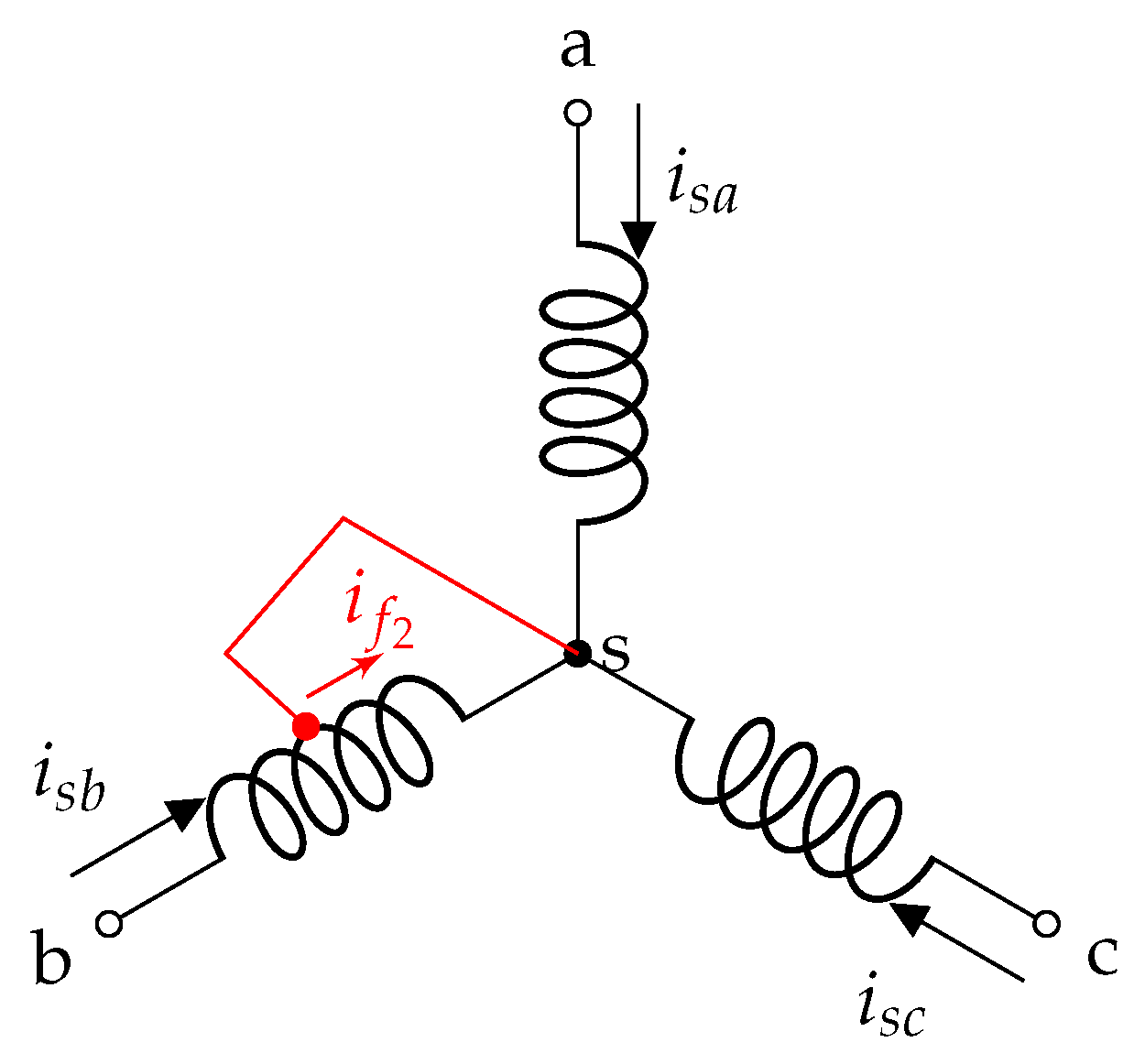
To describe the ITSC fault at any level, in any single phase of the stator, a DFIG model in the abc reference frame is proposed. The configuration of the DFIG with stator ITSC fault in phase (b) is shown in Figure 2. To develop an analytical model of the DFIG that accurately characterizes the behavior under an ITSC fault, two key parameters μ and f x are introduced to represent the fault level and its location, respectively. The parameter μ denotes the level of the fault and is defined as the ratio of the number of short-circuited turns to the total number of turns in the affected stator phase. The fault location parameter f x identifies the stator phase where the ITSC fault occurs (i.e., phase a, b, or c) and is defined as follows:
f a = 1 0 0 T , f b = 0 1 0 T , f c = 0 0 1 T
The equations of the voltage and flux linkage are given as follows:
V a b c _ s V a b c _ r V f = R s _ a b c 0 3 × 3 μ R s _ a b c f x 0 3 × 3 R r _ a b c 0 3 × 1 μ f x T R s _ a b c 0 1 × 3 μ r s I a b c _ s I a b c _ s i f + d d t ϕ a b c _ s ϕ a b c _ r ϕ f
where
ϕ a b c _ s ϕ a b c _ r ϕ f = L s s L s r μ L s s f x L r s L r r μ L r s f x μ f x T L s s μ f x T L s r μ L f I a b c _ s I a b c _ r i f
The matrices of the resistance and the inductance are given as follows:
R s _ a b c = r s 0 0 0 r s 0 0 0 r s , R r _ a b c = r r 0 0 0 r r 0 0 0 r r , L s s = L f s + M s 1 2 M s 1 2 M s 1 2 M s L f s + M s 1 2 M s 1 2 M s 1 2 M s L f s + M s , L r r = L f r + M r 1 2 M r 1 2 M r 1 2 M r L f r + M r 1 2 M r 1 2 M r 1 2 M r L f r + M r , L s r = M s r cos θ r cos θ r + 2 π 3 cos θ r 2 π 3 cos θ r 2 π 3 cos θ r cos θ r + 2 π 3 cos θ r + 2 π 3 cos θ r 2 π 3 cos θ r
L f s and L f r represent the leakage inductance of the stator and the rotor. M s , M r , and M s r are the stator, rotor, and stator–rotor mutual inductances.

2.3. DFIG Model in the d-q Reference Frame with ITSC Fault

A DFIG model in the d-q reference frame is obtained by transforming Equations (5) and (6) into a stationary d-q coordinate system. The parameter f x identifies the stator phase affected by the fault in the phases a, b, or c. In the d-q reference frame, the f x matrices associated with each phase are given as follows [11,12,13,14]:
f a = 1 0 T , f b = 1 2 3 2 T , f c = 1 2 3 2 T
As in the healthy case, the modeling of the DFIG in the d-q reference frame with the presence of a stator ITSC fault is given as follows [10,11]:
V d q s V d q r V f = R s 0 2 × 2 2 3 μ r s f x 0 2 × 2 R r 0 2 × 1 μ r s f x T 0 1 × 2 μ r s I d q s I d q r i f + d d t ϕ d q s ϕ d q r ϕ f + Ω m ϕ d q s ϕ d q r ϕ f
ϕ d q s ϕ d q r ϕ f = L s s L s r 2 3 μ L s s f x L r s L r r 2 3 μ L r s f x μ f x T L s s μ f x T L s r μ L f I d q s I d q r i f , Ω m = J ω s 0 2 × 2 0 0 2 × 2 J ω r 0 0 0 0
where ϕ d q s , ϕ d q r and ϕ f denote the dq-axis stator flux, the dq-axis rotor flux, and the short-circuited flux linkages, respectively. J = 0 1 1 0 , ω s = ω m + ω r is the synchronous speed of the generator, ω r is the the rotor angular frequency, and ω m is the electrical rotor speed. The matrices representing resistance and inductance are given below:
R s = r s 0 0 r s , R r = r r 0 0 r r , L s s = L s 0 0 L s , L r r = L r 0 0 L r , L s r = L m 0 0 L m
The following equations express the self-inductance of the stator and the rotor winding, including the ITSC fault:
L s = L m + L f s L r = L m + L f r , L f = L f s + 2 3 μ L m
where L m = 3 2 M s designates the mutual inductance. The electromagnetic torque in the d-q frame is defined as follows [11,12]:
C e m = p L m 3 2 I d q s × I d q r + μ i f f x I d q r
where p is the number of pole pairs.
To make the unknown input appear in the faulty state model, we define the θ parameter as follows:
θ = 2 μ 2 μ 3

2.4. State Space Model

Designing both fault compensation controllers and fault detection observers requires an analytical model of the DFIG in state-space form. This modeling approach has the advantage of describing the dynamic behavior of the DFIG system under healthy ( μ = 0 ) and faulty ( μ 0 ) conditions. According to Lu et al. [11], considering the currents as state variables allows (7) and (8) to be reformulated as follows:
x ˙ ( t ) = A x ( t ) + B c u ( t ) + ( B θ u ( t ) ) θ ( t ) y ( t ) = C x ( t )
The state matrix is defined as A = A c + A ω ω m , the state space vector x ( t ) = i s d i s q i r d i r q μ i f , the input control u ( t ) = u s d u s q u r d u r q , and ω m = p Ω m where Ω m = G Ω t u r represents the mechanical angular speed of generator and G is the Gearbox Ratio.
The matrices A c , A ω , B c , B θ , and C are given as follows:
A c = 1 D L r r R s L s r R r 2 3 r s L r f x L s r R r L s s R r 2 3 r s L m f x 0 1 × 2 0 1 × 2 0 + 1 L f s 0 2 × 2 0 2 × 2 2 3 r s f x 0 2 × 2 0 2 × 2 0 2 × 1 0 1 × 2 0 1 × 2 r s , A ω = 1 D L m 2 J L r L m J 2 3 L m 2 J f x L s L m J L s L r J 2 3 L s L m J f x 0 1 × 2 0 1 × 2 0 , B c = 1 D L r r L s r L s r L s s 0 1 × 2 0 1 × 2 , B θ = 1 L f s 2 f x f x T 0 2 × 2 0 2 × 2 0 2 × 2 3 f x T 0 1 × 2 , C = I 4 × 4 0 4 × 1 0 1 × 4 0
where D = L s L r L m 2 .
The voltage V f in the short-circuit loop can be regarded as zero as long as the resistance in the insulation break is zero [11].

2.5. T-S Fuzzy Model of the DFIG with ITSC Fault

Model (11) is used for the T-S fuzzy Unknown Input Observer design, and according to Lu et al. [11], it can be rewritten as follows:
x ˙ ( t ) = A x ( t ) + B c u ( t ) + R θ ( t )
where θ ( t ) is the unknown input and R = ( B θ u ( t ) ) = 1 L f s 2 f x f x T 0 2 × 2 3 f x T u s d u s q .
For all ITSC stator fault positions that occur in Phases (a), (b), and (c), f x f x T takes the following form [11]:
f a f a T = 1 0 0 0 , f b f b T = 1 4 3 4 3 4 3 4 , f c f c T = 1 4 3 4 3 4 3 4
Therefore, depending on the position where the ITSC fault occurs in the stator winding, the matrix R is calculated as
R a = 1 L f s 2 u s d 0 3 × 1 3 u s d , R b = 1 L f s 1 2 u s d + 3 2 u s q 3 2 u s d 3 2 u s q 0 2 × 1 3 2 u s d 3 3 2 u s q , R c = 1 L f s 1 2 u s d 3 2 u s q 3 2 u s d + 3 2 u s q 0 2 × 1 3 2 u s d + 3 3 2 u s q
In addition, in the wind energy conversion system, the rotor speed ω m changes with the variation of the wind speed, which allows to consider Model (12) as an LPV system. Based on the well-known sector nonlinearity approach, a T-S fuzzy model is developed where the nonlinear terms of the LPV model (12) are considered as “premise variables” and denoted by z k ( t ) , k = ( 1 , 2 , 3 ) . For 3 premise variables, 2 3 submodels are obtained. Thus, for all ITSC stator fault positions that occur in the stator winding, the LPV model (12) includes the following three nonlinearities:
z 1 ( t ) = ω m ( t ) z 2 ( t ) = u s d ( t ) z 3 ( t ) = u s q ( t )
Let us now consider the membership functions F i j ( z ( t ) ) of each premise variable z k ( t ) , in which the fuzzy subsets F i j are defined as follows:
F k , min ( z ( t ) ) = z k ( t ) min z k ( t ) max z k ( t ) min z k ( t ) F k , max ( z ( t ) ) = max z k ( t ) z k ( t ) max z k ( t ) min z k ( t ) k = { 1 , 2 , 3 }
Hereafter, we describe the DFIG affected by the ITSC fault by means of a T-S fuzzy model such as the ith rule is written as follows:
Rule R i : If z 1 ( t ) is F 1 , i and z 2 ( t ) is F 2 , i and z 3 ( t ) is F 3 , i Then x ˙ ( t ) = A i x ( t ) + B c u ( t ) + R i θ ( t ) , i = { 1 , 2 , , 8 }
A multimodel representation is the result of interpolating local models through weighting functions h i ( z ( t ) ) as follows:
x ˙ ( t ) = i = 1 8 h i ( z ( t ) ) A i x ( t ) + B c u ( t ) + R i θ ( t ) y ( t ) = C x ( t ) + D θ ( t )
where the matrix D is added to take account of the influence of the unknown inputs on the output y ( t ) .

3. Unknown Input T-S Observer Design for Stator Inter-Turn Short Circuit Fault

3.1. Indirect Field-Oriented Control Strategy

The vector control strategy of the wind turbine DFIG machine consists of making the behavior of the DFIG analogous to the direct current machine with separate excitation by achieving the decoupling between the flux and the electromagnetic couple [12]. The field-oriented control strategy is shown in Figure 3. We choose to apply the vector control strategy to the DFIG by the orientation of the stator flux along the direct d-axis. In this case, we obtain the stator flux distribution as follows:
ϕ d s = ϕ s n ϕ q s = 0
where ϕ d s and ϕ q s denote the stator flux in the q-d frame. ϕ s n is the nominal stator flux.
By regulating the d - q voltage control signals via the generator-side AC-DC converter and the grid-side DC-AC inverter, active and reactive power can be controlled independently. Consequently, through the generator-side converter, the aerodynamic power captured by the rotor can be adjusted in accordance with the reference rotor speed, enabling maximum power extraction and ensuring that the generator operates within its optimal performance zone.

3.2. Unknown Input TS Observer Design

This section focuses on determining the ITSC fault level in the stator winding, which involves estimating the fault severity parameter μ . The estimation is performed using an Unknown Input Observer (UIO), which enables the reconstruction of the system states despite the presence of an unknown input θ ( t ) affecting the system. The proposed UIO is designed to decouple the influence of θ ( t ) from the estimation error, thereby making the observer robust to this unknown input. Achieving perfect decoupling requires certain structural conditions to ensure that the estimation error is entirely insensitive to θ ( t ) . Once the system state x(t) is estimated, it is subsequently used to reconstruct the unknown input θ ( t ) , as shown in (33). Let us recall the following assumption used to determine the observer gains before proposing the structure of the observer.
Assumption 1.
The existence of Unknown Input Observer is dependent on certain conditions (16):
  • matrix D and R i are full column ranks.
  • rank(D) = rank( R i )
Therefore, to estimate the states of the unknown input Takagi-Sugeno (T-S) fuzzy model defined in Equation (16), we adopt the structure of an unknown input T-S fuzzy observer as follows:
η ˙ ( t ) = i = 1 8 h i z ( t ) N i η ( t ) + G i ( t ) u ( t ) + L i y ( t ) x ^ ( t ) = η ( t ) E y ( t ) .
The matrices N i R n × n , G i R n × m , L i R n × p , and E R n × p are the observer gains. We define the state estimation error:
e ( t ) = ( I + E C ) x ( t ) η ( t ) + E D θ ( t )
The expression for the estimation error dynamics is given by
e ˙ ( t ) = i = 1 8 h i ( z ( t ) ) ( N i e ( t ) + P A i K i C + N i x ( t ) + P B c G i u ( t ) + P R i K i D θ ( t ) ) + E D θ ˙ ( t )
with P = I + E C and K i = N i E + L i .
By imposing the following conditions,
E D = 0
P R i = K i D
G i = P B c
N i = P A i K i C
L i = K i N i E
Equation (20) reduces to
e ˙ ( t ) = i = 1 8 h i z ( t ) N i e ( t )
The stability analysis of the UIO observer (18) relies on the existence of a positive definite matrix X that satisfies the following condition:
N i T X + X T N i < 0
The following theorem provides sufficient Linear Matrix Inequality (LMI) conditions to guarantee the global asymptotic convergence of the state estimation error (19).
Theorem 1.
The state estimation error between the T-S fuzzy model (16) and the unknown inputs observer (18) converges asymptotically towards zero. If there exist a positive definite matrix X > 0 and matrices S and W i such that the following conditions are satisfied, i = 1 , 2 , , 8 :
A i T X + X A i + S C A i + A i T C T S T W i C C T W i T < 0
( X + S C ) R i = W i D
S D = 0
where K i = X 1 W i
Proof. 
Taking account of the relation (24) and P = I + E C , (27) is equivalent to
A i + E C A i K i C T X + X T A i + E C A i K i C < 0
By developing (31), we obtain
A i T X + A i T C T E T X C T K i T X + X T A i + X T E C A i X T K i C < 0
By considering the variable change W i = X K i and S = X E , LMI (28) is obtained. Similarly, by using the relation S = X E and P = I + E C , we have X + S C R i = X P R i . According to (22), this latter becomes X + S C R i = X K i D . By considering the variable change W i = X K i , LMI (29) is proven. In addition, according to (21) and using equation S = X E , we can obtain Condition (30). □
So, by determining the matrices X, S, W i , and K i from Theorem 1, the matrices defining the Unknown Input Observer (18) are then deduced as follows:
E = X 1 S P = I + E C N i = P A i K i C L i = K i N i E G i = P B c
Finally, the estimate of the unknown input θ ( t ) is given by the following equation:
θ ^ ( t ) = W T W 1 W T x ^ ˙ ( t ) i = 1 8 h i ( z ( t ) ) A i x ^ ( t ) + B c u ( t ) ,
where W = i = 1 8 h i ( z ( t ) ) R i .
Equation (10) can be used to estimate the ITSC fault level μ ( t ) once parameter θ ( t ) is estimated.

4. Fault-Tolerant Controller Design Subject to ITSC Faults

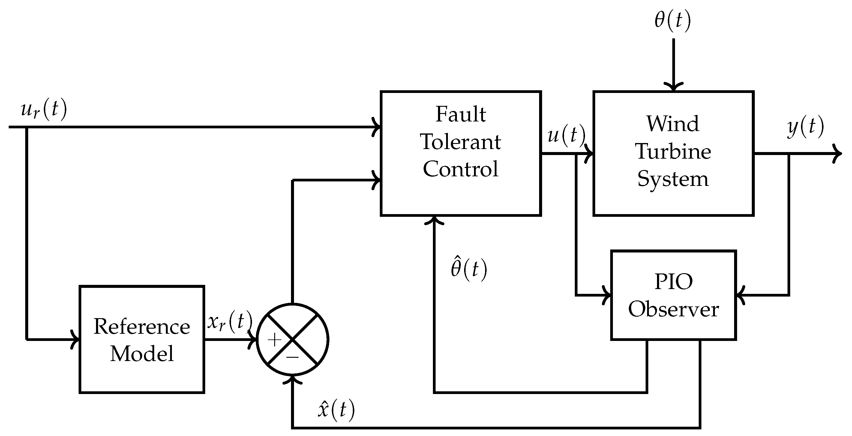
This section is dedicated to the synthesis of a fault-tolerant controller as shown in Figure 4, which guarantees convergence of the state x(t) to the reference state x r ( t ) , generated by the fault-free model, which is able to
  • ensure a decoupling between torque and stator flux;
  • compensate the effect of the ITSC fault and maintain normal operation of the machine even in faulty mode;
  • maintain the optimal operation of the generator regardless of the variation of the wind speed.
Once the diagnostic task is performed, the fault occurring in the stator winding is detected, located, and then estimated. It is then natural to seek to limit its effect on the wind turbine system by an appropriate control law, known as fault-tolerant control, which is able to avoid or attenuate the fault effect. A Proportional Integral Observer (PIO) is proposed to simultaneously estimate the DFIG states and ITSC fault level. It is recognized that the addition of integral action in the observer allows to obtain robustness against model uncertainties and provides a good estimation of the unknown input even in the presence of noise measurement.
In order to force the wind turbine to operate in the maximum power zone and to ensure decoupling between the torque and the stator flux, we consider in the following a T-S reference model without ITSC fault, in which parameter μ is assumed to be zero. In fault-free operating conditions of the DFIG, the unknown input θ ( t ) = 0 . Thus, the LPV model (12) is made up of one nonlinearity defined by the premise variable z ( t ) = ω m ( t ) and this implies two local models defined by the T-S reference model.
x ˙ r ( t ) = i = 1 2 h i z ( t ) A i x r ( t ) + B c u r ( t )
with
A 1 = A c + A ω ω m i n , A 2 = A c + A ω ω m a x , B c = 1 σ L s 0 L m σ L s L r 0 0 1 σ L s 0 L m σ L s L r L m σ L s L r 0 1 σ L r 0 0 L m σ L s L r 0 1 σ L r 0 0 0 0 , u r ( t ) = u s d r e f u s q r e f u r d r e f u r q r e f
and σ = 1 L m 2 L s L r .
The generator reference voltages leading to the optimal operation are given by
u s d r e f = 0 u s q r e f = ω s ϕ s n u r d r e f = R r I d r r e f ω s p Ω m r e f σ L r I q r r e f u r q r e f = R r I q r r e f + ω s p Ω m r e f L m L s ϕ s n + σ L r I d r r e f
where
I d r r e f = L s V s L m Q s r e f V s 2 L s ω s I q r r e f = L s L m p ϕ s n C t u r _ r e f G + f Ω m r e f + J d Ω m r e f d t
J is the total inertia of the system at the high speed shaft of the turbine and f is the viscous friction.
The synthesis of the FTC control law involves the incorporation of an additional PIO observer, which is structured as follows:
x ^ ˙ ( t ) = i = 1 8 h i z ( t ) A i x ^ ( t ) + B u ( t ) + R i θ ( t ) + L 1 i ( y ( t ) y ^ ( t ) )
θ ^ ˙ ( t ) = i = 1 8 h i z ( t ) L 2 i ( y ( t ) y ^ ( t ) )
y ^ ( t ) = i = 1 8 h i z ( t ) C i x ( t ) + D i θ ( t )
where L 1 i and L 2 i are the PI observer’s gain.
The maximum power trajectory is tracked by a fault-tolerant controller, which is given by the following expression:
u ( t ) = j = 1 8 h j z ( t ) K 1 j x r ( t ) x ^ ( t ) K 2 j ( t ) θ ^ ( t ) + u r ( t )
where K 1 j R m × n and K 2 j R m × q are the controller gains. For reconfiguration to an augmented model, we define the tracking error e r ( t ) , the estimation error e s ( t ) , and the estimation error of the fault e f ( t ) as follows:
e r ( t ) = x r ( t ) x ( t )
e s ( t ) = x ( t ) x ^ ( t )
e f ( t ) = θ ( t ) θ ^ ( t )
According to (39)–(41), the FTC expression (38) can be rewritten as
u ( t ) = j = 1 8 h j z ( t ) K 1 j e r ( t ) + e s ( t ) + K 2 j ( t ) e f ( t ) θ ( t ) + u r ( t )
Substituting (16), (34), and (42) into (39), the dynamic of the tracking error e r ( t ) becomes
e ˙ r ( t ) = i = 1 8 j = 1 8 h i ( z ( t ) ) h j ( z ( t ) ) A i B c K 1 j e r ( t ) B c K 1 j e s ( t ) B c K 2 j e f ( t ) + B c K 2 j R i θ ( t )
Similarly, the dynamics of the estimation error (40) is given as
e ˙ s ( t ) = i = 1 8 A i + L 1 i C e s ( t ) + L 1 i D + R i e f ( t )
In the following, we assume that the ITSC fault affecting the stator winding is constant, i.e., θ ˙ ( t ) = 0 ; thus, the dynamics of Equation (41) is defined as
e ˙ f ( t ) = i = 1 8 L 2 i C e s ( t ) L 2 i D e f ( t )
The augmented system can be defined in closed-loop form with considered the state vector x ¯ ( t ) = e r ( t ) e s ( t ) e f ( t ) T as follows:
x ¯ ˙ ( t ) = i = 1 8 j = 1 8 h i ( z ( t ) ) h j ( z ( t ) ) A ¯ i j x ( t ) + E ¯ i j θ ( t )
where
A ¯ i j = A i B c K 1 j B c K 1 j B c K 2 j 0 A i + L 1 i C R i L 1 i D 0 L 2 i C L 2 i C , E ¯ i j = B c K 2 j R i 0 0
Here, θ ( t ) can be considered as an external disturbance including parameter μ . The effect of the disturbance on the closed-loop control system can be efficiently attenuated by the H tracking performance as follows [6]:
x ¯ T ( t ) Q ¯ x ¯ ( t ) d t θ T ( t ) θ ( t ) ρ
where ρ is positive scalar and Q ¯ is defined as follows:
Q ¯ = Q 0 0 0 0 0 0 0 0
Thus, the objective of the active fault-tolerant controller design is to determine the fuzzy controller gains (42) and the PIO observer gains (35) such that the H tracking performance (48) is minimized and the effect of the ITSC fault is compensated which allows normal operation of the DFIG. Thus, we propose the following theorem.
Theorem 2.
The fault-tolerant control (42) ensuring convergence of the state x ( t ) to the reference state x r ( t ) and minimizing the L 2 gain of the unknown input θ ( t ) on the tracking error e r ( t ) exists, if, for a positive scalar ε, there exist positive definite symmetric matrices P 1 = X 1 1 R 5 × 5 , P 2 5 × 5 , and P 3 I R 1 × 1 , matrices Y i I R 4 × 5 , Z i R 5 × 5 , W i 1 × 5 , and gains K 2 i I R 4 × 1 that minimize the positive scalar ρ satisfying the following LMI conditions:
Π 11 B c Y j B c K 2 j B i K 2 j R i 0 5 × 5 0 5 × 1 0 5 × 1 X 1 2 ε X 1 0 5 × 1 0 5 × 1 ε I 5 × 5 0 5 × 1 0 5 × 1 0 5 × 5 2 × I 1 × 1 0 1 × 1 0 1 × 5 ε I 1 × 1 0 1 × 1 0 1 × 5 0 1 × 1 2 ε I 1 × 1 0 1 × 5 0 1 × 1 ε I 1 × 1 0 1 × 5 0 5 × 1 Π 66 Π 67 0 5 × 1 0 5 × 5 Π 77 0 1 × 1 0 1 × 5 ρ I 1 × 1 0 1 × 5 Q 1 < 0 , i = 1 , 2 , , 8
with
Π 11 = Sym A i X 1 B c Y j , Π 66 = Sym A i P 2 + Z i C , Π 77 = Sym W i D i
The controller and the observer gains are given by K 1 i = Y i X 1 1 , L 1 i = P 2 1 Z i , and L 2 i = P 3 1 W i .
Proof. 
The following quadratic Lyapunov function is defined:
V ( x ¯ ( t ) ) = x ¯ T ( t ) P ¯ x ¯ ( t )
where P ¯ = diag P 1 , P 2 , P 3 .
To achieve the stability of Equation (46) with the H tracking performance (48), the following inequality must hold:
V ˙ ( x ¯ ( t ) ) + x ¯ T ( t ) Q ¯ x ¯ ( t ) ρ 2 θ T ( t ) θ ( t ) < 0
By considering the dynamics of Equation (50), Inequality (51) becomes
i = 1 8 j = 1 8 h i ( z ( t ) ) h j ( z ( t ) ) x ¯ ( t ) θ ( t ) T A ¯ i j T P ¯ + P ¯ A i j + Q ¯ P ¯ E ¯ i j E ¯ i j T P ¯ ρ 2 I x ¯ ( t ) θ ( t ) < 0
and using congruent transformations, (52) becomes
A ¯ i j T P ¯ + P ¯ A ¯ i j + Q ¯ P ¯ E ¯ i j E ¯ i j T P ¯ ρ 2 I < 0
with P ¯ = diag P 1 , P 2 , P 3 in mind and after simple manipulations, Inequality (53) can be reformulated as follows:
Π i j = Π i j 11 P 1 B c K 1 j P 1 B c K 2 j P 1 B c K 2 j R i Π i j 22 Π i j 23 0 Sym P 3 L 21 D 0 ρ 2 I = Π i j 11 Π ¯ i j 12 Π ¯ i j 22 < 0
with
Π i j 11 = Sym P 1 A 1 B c K 1 j + Q Π i j 22 = Sym P 2 A 1 + L 1 i C Π i j 23 = P 2 R i + L 1 i D P 3 L 2 i C T
Inequality (54) is a bilinear matrix (BMI). Pre-and post-multiplying (54) by diag P 2 1 X with X = diag P 1 1 I I yields
P 1 1 Π i j 11 P 1 1 P 1 1 Π ¯ i j 12 X X Π ¯ i j 22 X < 0
If Inequality (55) is verified, this implies that P 1 1 Π i j 11 P 1 1 < 0 and X Π ¯ i j 22 X < 0 , so there exists a positive scalar ε such as the following inequality is verified:
X Π ¯ i j 22 X < 2 ε X ε 2 Π ¯ i j 22 1
Since Π ¯ i j 22 < 0 , we obtain
X + ε Π ¯ i j 22 1 Π ¯ i j 22 X + ε Π ¯ i j 22 1 < 0
By substituting (56) in (55) and applying a Schur complement, we obtain
P 1 1 Π i j 11 P 1 1 P 1 1 Π ¯ i j 12 X 0 2 ε X ε I Π ¯ i j 22 < 0
After replacing Π i j 11 , Π ¯ i j 12 , and Π ¯ i j 22 by their analytical expressions from (54), and considering the variable change Y i = K 1 i X 1 , Z i = P 2 L 1 i , and W i = P 3 L 2 i , Inequality (57) is transformed into a standard LMI which ends the proof of Theorem 2. □

5. Simulation Results

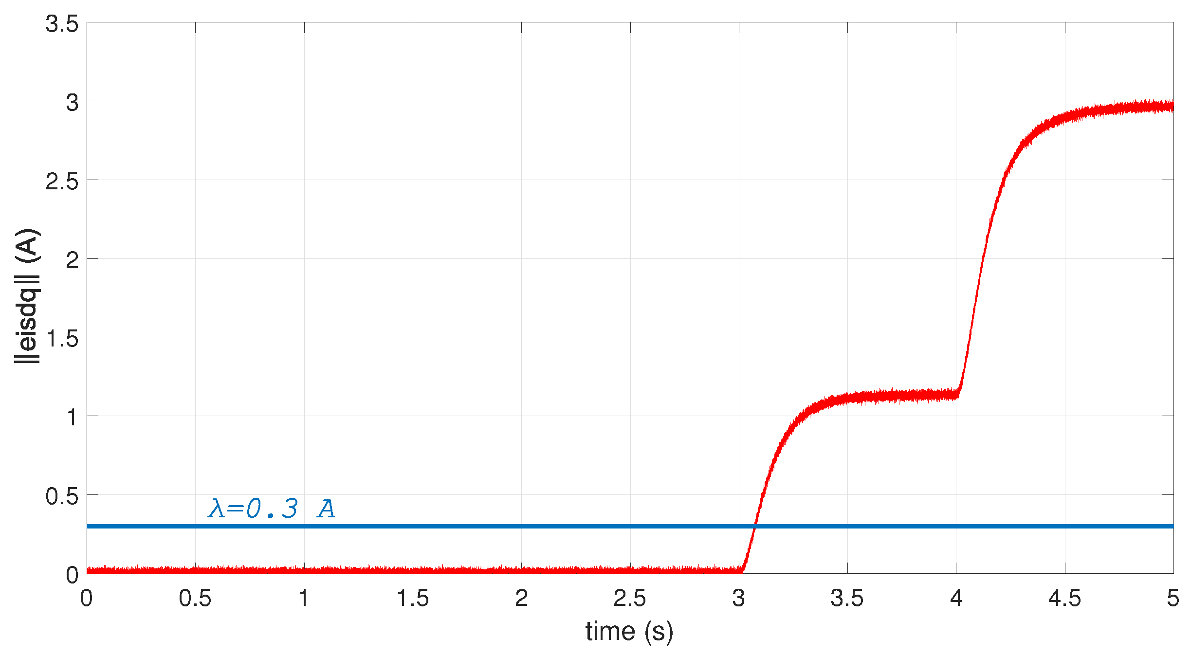
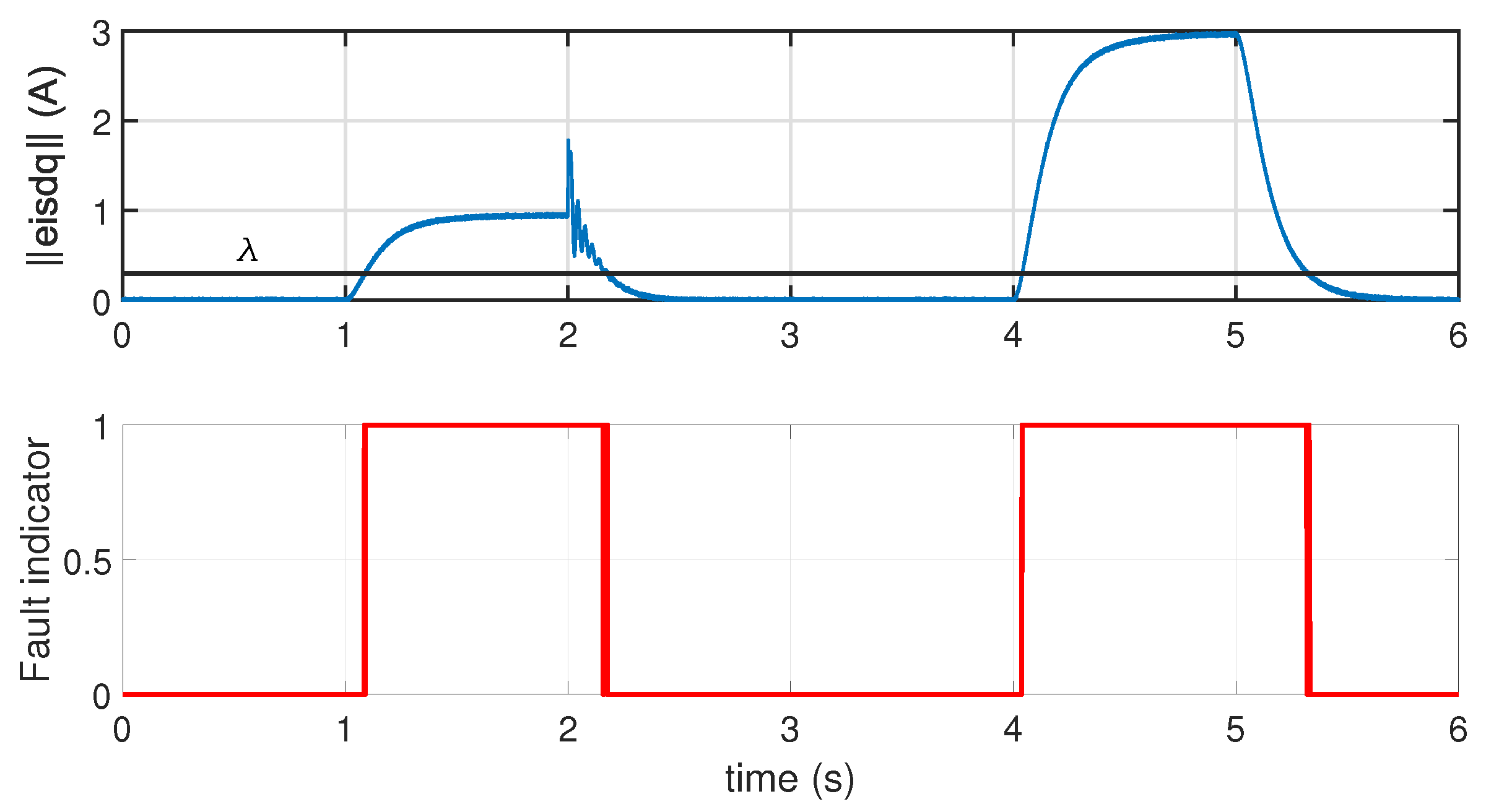
This section aims to evaluate the performance of the proposed unknown input T-S fuzzy observer for ITSC fault estimation and to verify the effectiveness of the designed FTC control law in mitigating the effect of ITSC faults. To demonstrate the effectiveness of the proposed multi-model observer in diagnosing various levels of ITSC faults, two fault scenarios in Phase (b) are considered: a 2 % short circuit at t = 3 s, followed by a 5 % short circuit at t = 4 s. Details of the wind power generator specifications are listed in Table 1. The proposed simulation test includes generating an alarm signal when a fault occurs by using a Luenberger observer [11] and subsequently evaluating the fault level by estimating the parameter μ by means of UIO observer, despite wind speed variations. The residual generated by the Luenberger observer is compared against a predefined threshold λ to achieve fault detection.
e i s d q = i s d q i ^ s d q < λ no   fault   occurence e i s d q = i s d q i ^ s d q λ fault   occurence
The accuracy of the T-S model which represents the dynamic behavior of the DFIG system (11) within the bounded interval of the premise variables: Ω m i n = 200 rd/s, Ω m a x = 200 rd/s, u s d m i n = 100 V, u s d m a x = 100 V, u s q m i n = 380 V, u s q m a x = 380 V. The resolution of the LMIs (28)–(30) of Theorem 1 leads to the observer gains of the local Model 1 as an example.
N 1 = 405 9340 592 3191 5365 9339 403 3188 587 3287 1285 3364 1949 1140 1933 3365 1281 1139 1935 1180 0.05 0.85 1 2.1 1.9 , E = 1 0 0 0 0 0 1 0 0 0 0 0 1 0 0 0 0 0 1 0 0 0 0 0 1
L 1 = 548 9242 1057 3162 5362 9242 545 3157 1048 3292 1753 3332 3470 1130 1932 3332 1745 1129 3444 1181 0.1 0.1 0 0 1.9 , G 1 = 1348 0 4214 0 0 0 1348 0 4214 0 4214 0 1422.2 0 0 0 4214 0 1422.2 0 0 0.01 0 0.05 0
The proposed TS unknown observer is tested for a step range of wind speed from 8 m/s to 10 m/s at 2 s. We assume that the stator current sensors are affected by zero-mean measurement noise with a maximum amplitude of 0.25. Figure 5 shows the simulation results of the the norm of d-q stator current error. As shown in Table 2, setting the detection threshold to 0.3 A enables the FDI system to detect a 2 % ITSC fault within approximately 0.091 (s). This result demonstrates the sensitivity and effectiveness of the proposed FDD system.
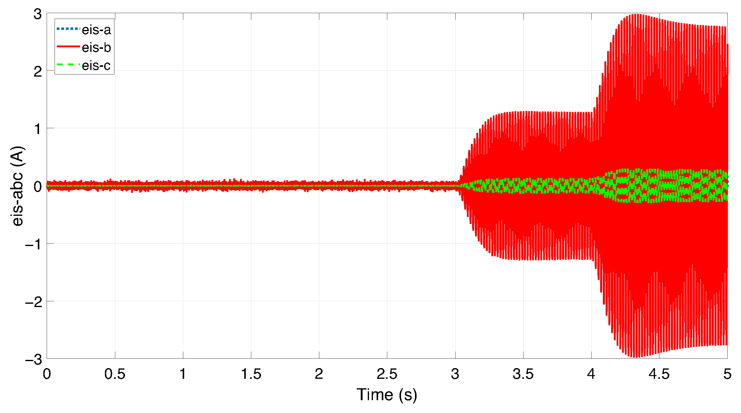
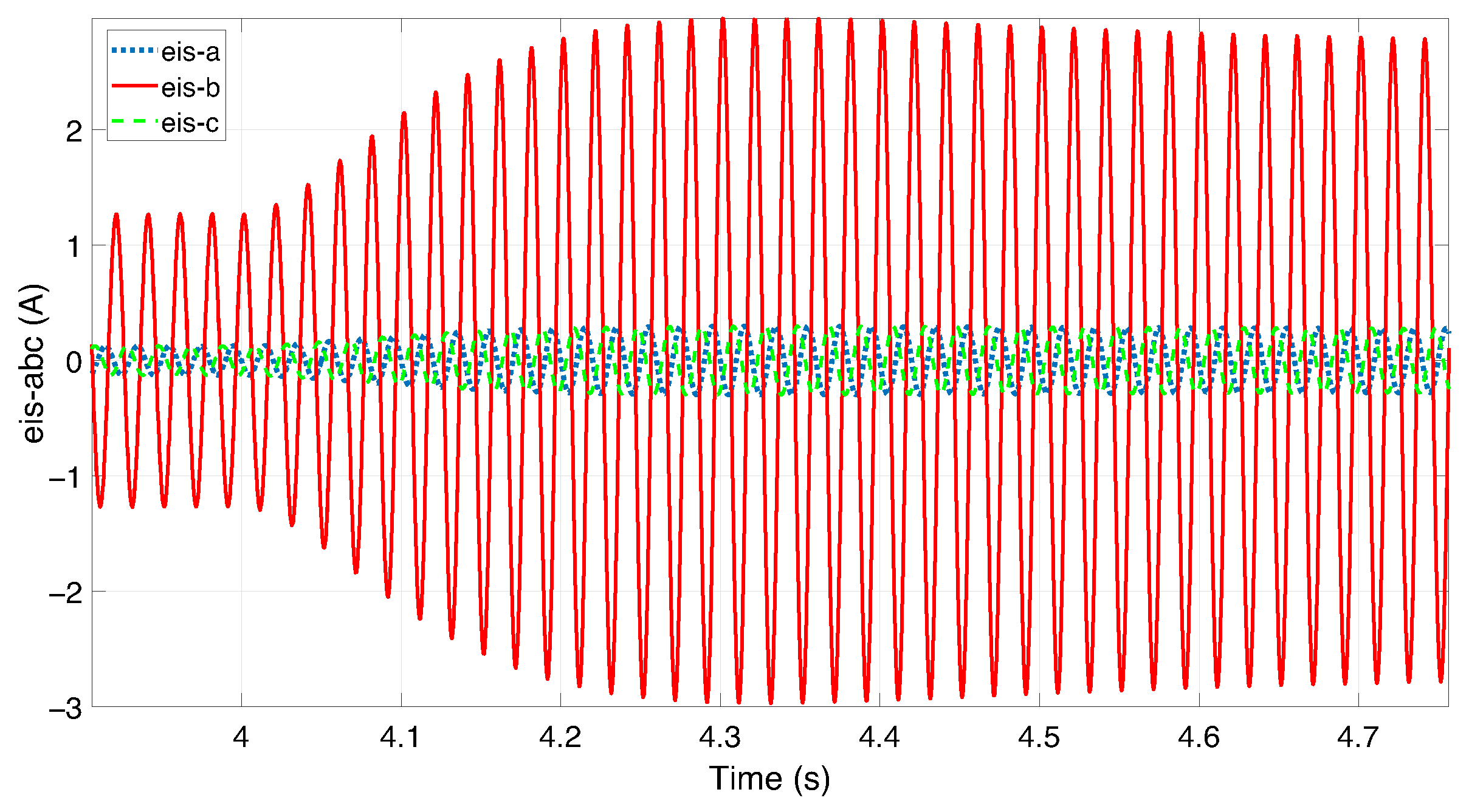
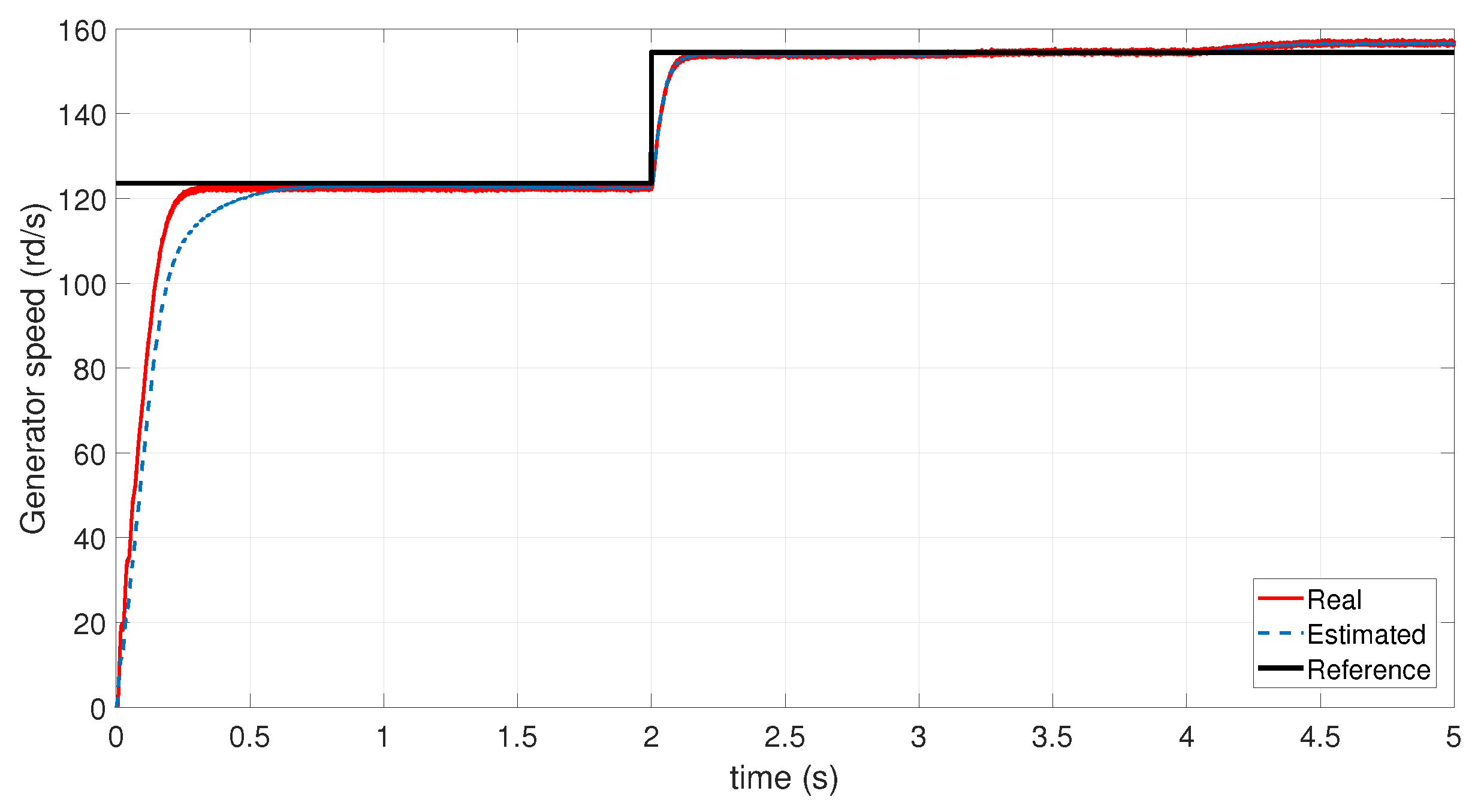
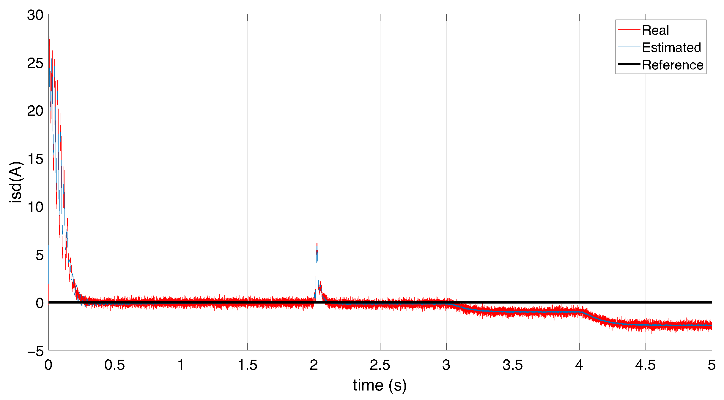
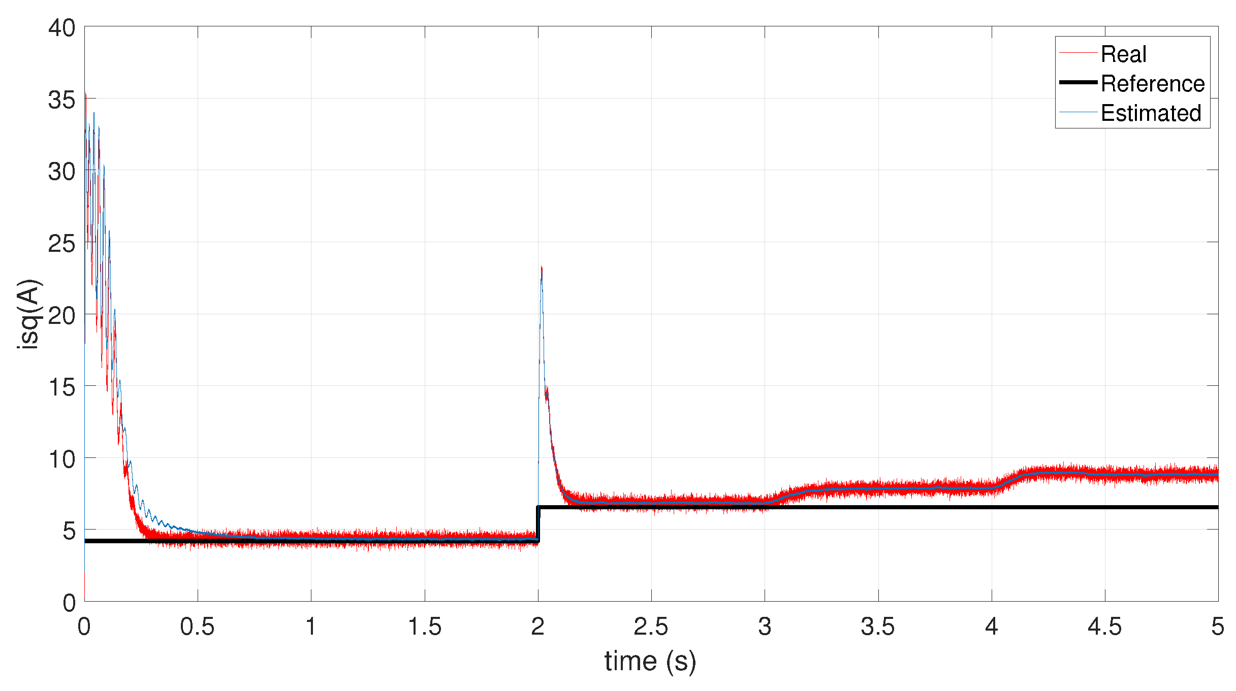
Figure 6 and Figure 7 show that as the number of short-circuited winding becomes significant, the residuals of the phase affected by the ITSC fault increase. This is because the short circuit reduces the effective impedance of the faulted phase. Figure 8, Figure 9 and Figure 10 illustrate the estimated d - q stator current and rotor speed for initial condition of the UIO observer x 0 equal to two for all state variables. The performance metrics presented in Table 3 under zero initial conditions highlight the effectiveness of the Unknown Input Observer (UIO) in accurately estimating the system’s state variables. The d-axis and q-axis stator currents exhibit low RMSE and MAE values (approximately 0.14 and 0.11, respectively), indicating a high level of accuracy. Additionally, the small gap between RMSE and MAE suggests that the estimation errors are consistently distributed without significant outliers. The maximum absolute errors for both currents remain below 0.71, confirming that transient deviations are well controlled. In the case of the generator speed, although the RMSE (0.1523) and MAE (0.1214) are slightly higher, the estimation remains within acceptable bounds. The higher maximum error (0.8154) may be attributed to transient dynamics. Nonetheless, the overall estimation quality remains satisfactory. These results confirm that the UIO provides robust and accurate state estimation for the DFIG system, even under the presence of ITSC fault and noise.
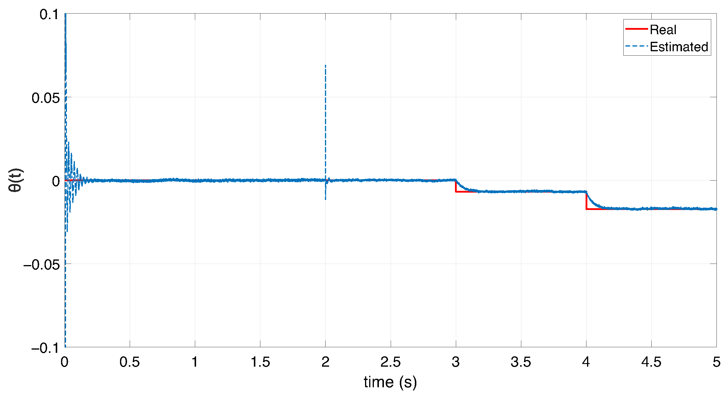
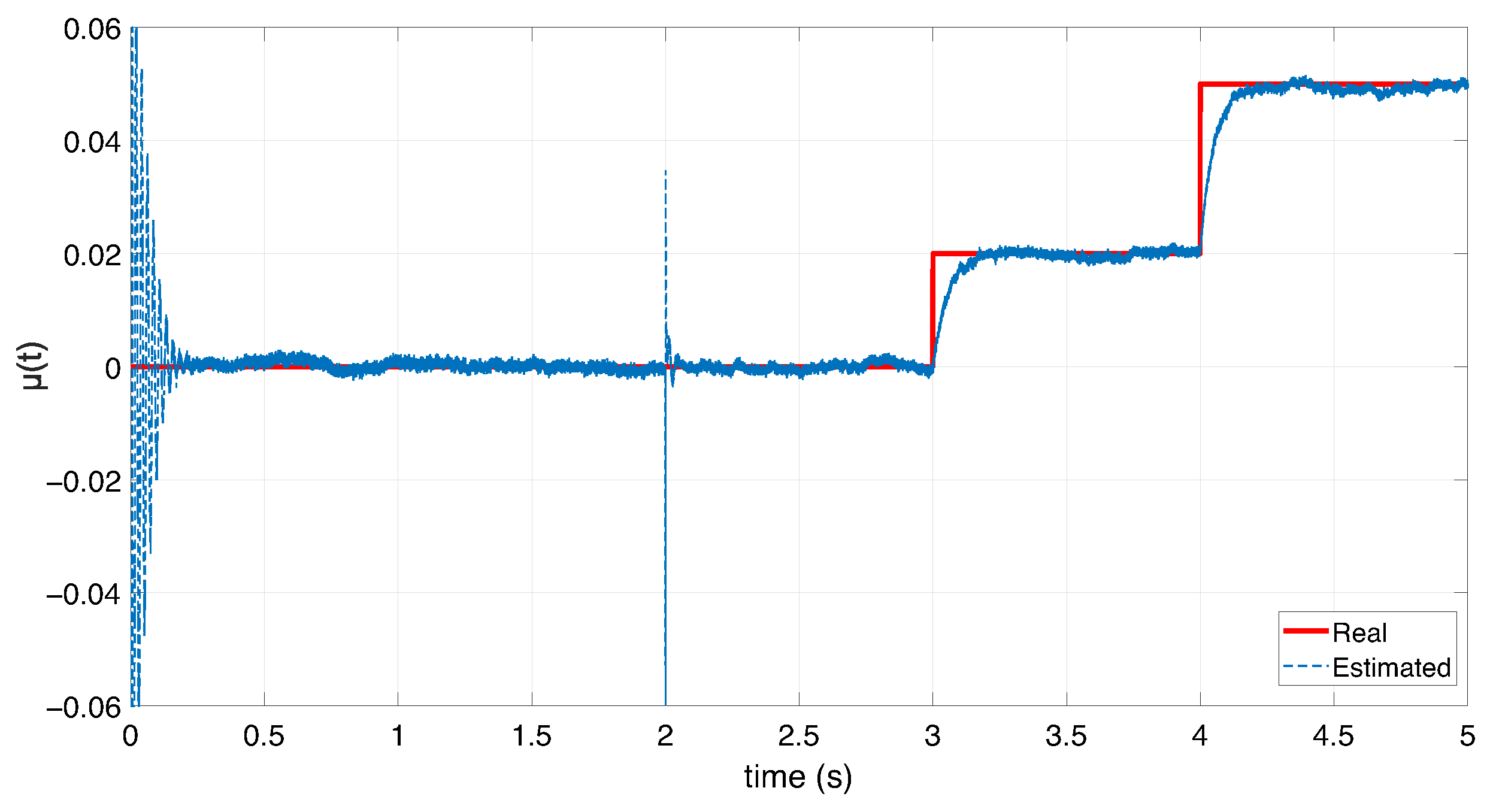
As illustrated in Figure 11 and Figure 12, the Unknown Input Observer (UIO) is capable of accurately and rapidly estimating the the unknown input θ ( t ) and therefore the stator winding short-circuit ratio μ ( t ) . It demonstrates tracking performance even in the presence of measurement noise, confirming its effectiveness for real-time detection of ITSC faults in DFIG generator. In industrial applicability, DFIGs can typically tolerate ITSC faults involving less than 1–2% of a stator phase’s winding without immediate shutdown. These levels are considered acceptable for short-term operation if the fault remains stable. Faults exceeding 5 % require immediate intervention to prevent further damage.
The following part is intended to present the simulation results of the developed FTC control law, based on the use of a PI observer able to simultaneously estimate the inter-turn short-circuit fault and the current state variable of the DFIG.
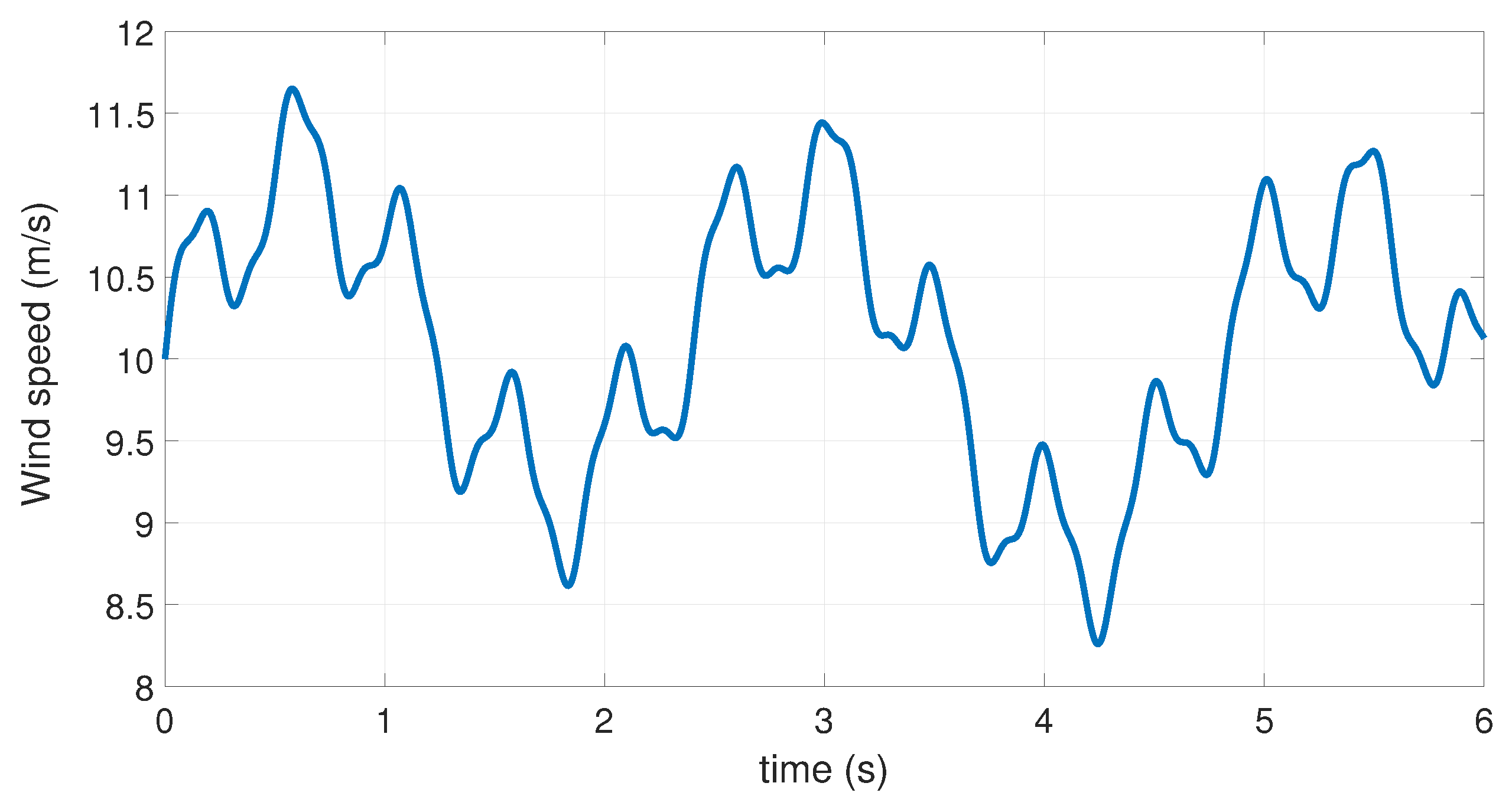
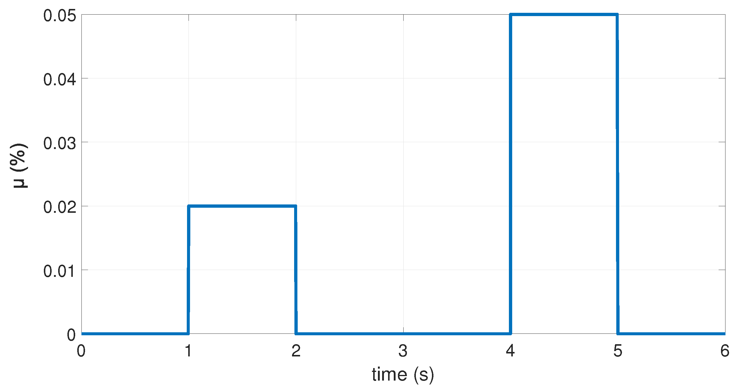
The structure of the FTC controller illustrated in Figure 4 shows that the efficiency of the proposed fault-tolerant controller depends on the accuracy of the estimation of the ITSC fault provided by the PI observer, which allows the reconfiguration of the TS controller in real time. To evaluate the robustness of the proposed fuzzy controller under varying wind speed conditions, a wind profile is generated by adding multiple sinusoidal signals, which results in the profile depicted in Figure 13. The DFIG can operate in hypersynchronous and hyposynchronous modes by varying the wind speed. A 2 % and 5 % inter-turn short-circuit fault sequence level affects the stator winding as shown in Figure 14. Here, we assume that the fault has a constant amplitude. Thus, with Q = 0.01 I 5 and ϵ = 0.1 , the resolution of the LMI (49) gives the controller and observer gains K 1 i , K 2 i , L 1 i , and L 2 i . The simulation results of the proposed fuzzy fault-tolerant controller are given in Figure 15, Figure 16, Figure 17, Figure 18, Figure 19, Figure 20, Figure 21, Figure 22 and Figure 23.
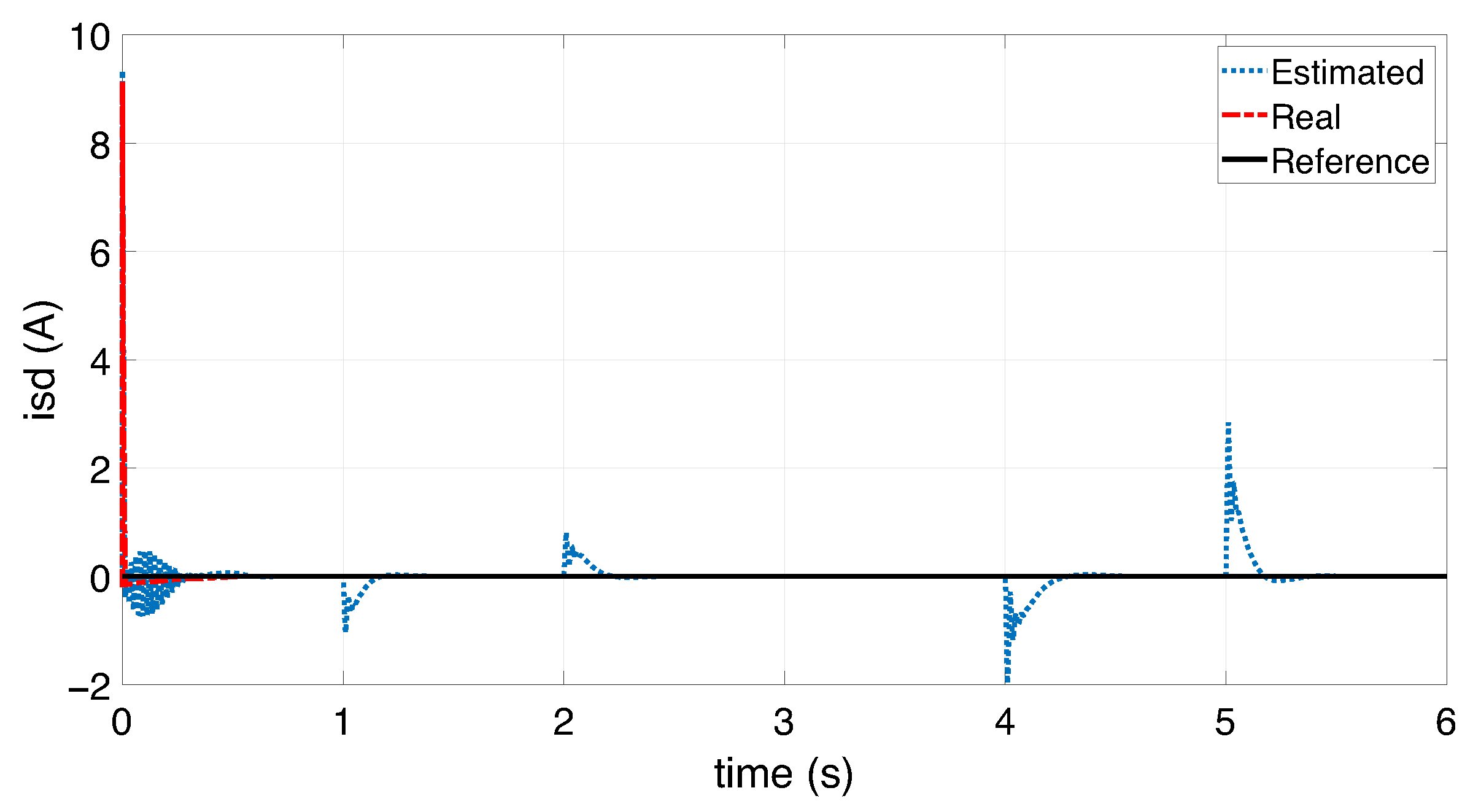
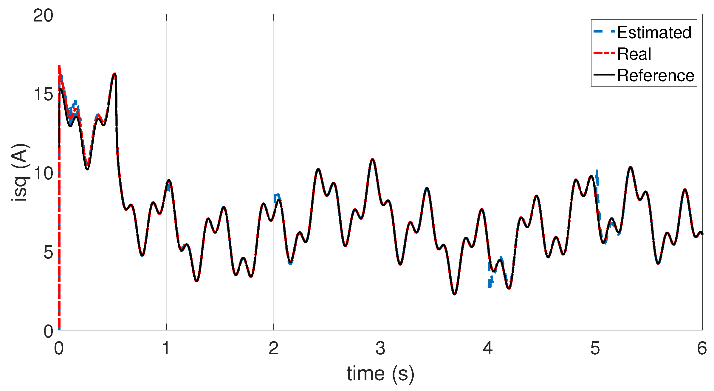
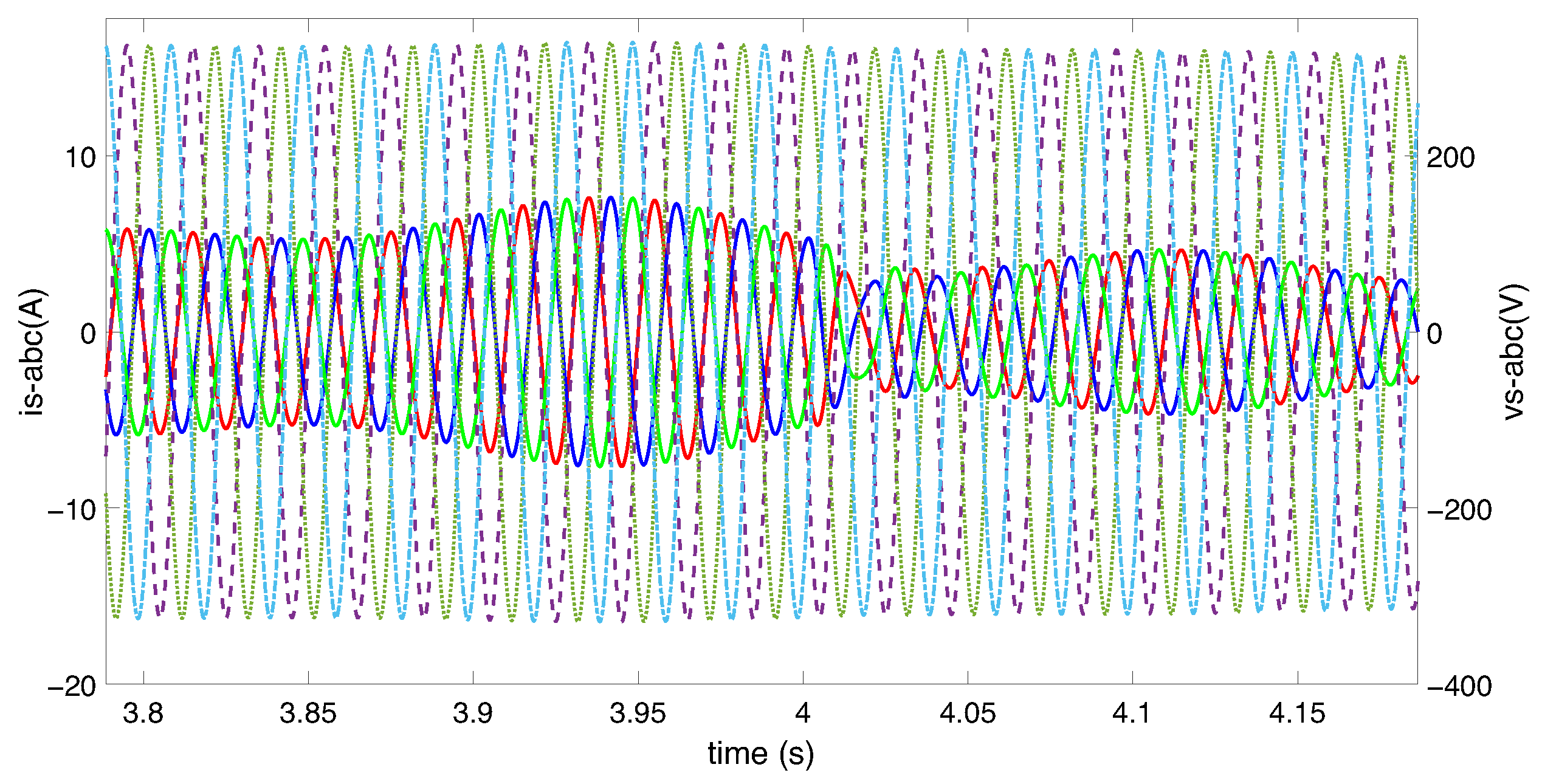
Figure 15 shows that the direct stator current remains at zero, with a Root Mean Square Error (RMSE) of 0.3218. This proves that decoupling between the torque and the stator flux is maintained and that the effect of the ITSC fault is compensated. This ensures that the stator current is only used for torque generation (i.e., the torque is proportional to the current I s q ) and the direct rotor current is constant, i.e., I d r = V s L m ω s . In Figure 16, the real and estimated quadratic stator currents follow the reference currents. This confirms that the wind turbine system maintains its tracking performance on the maximum power trajectory despite the presence of the inter-turn short circuit fault.
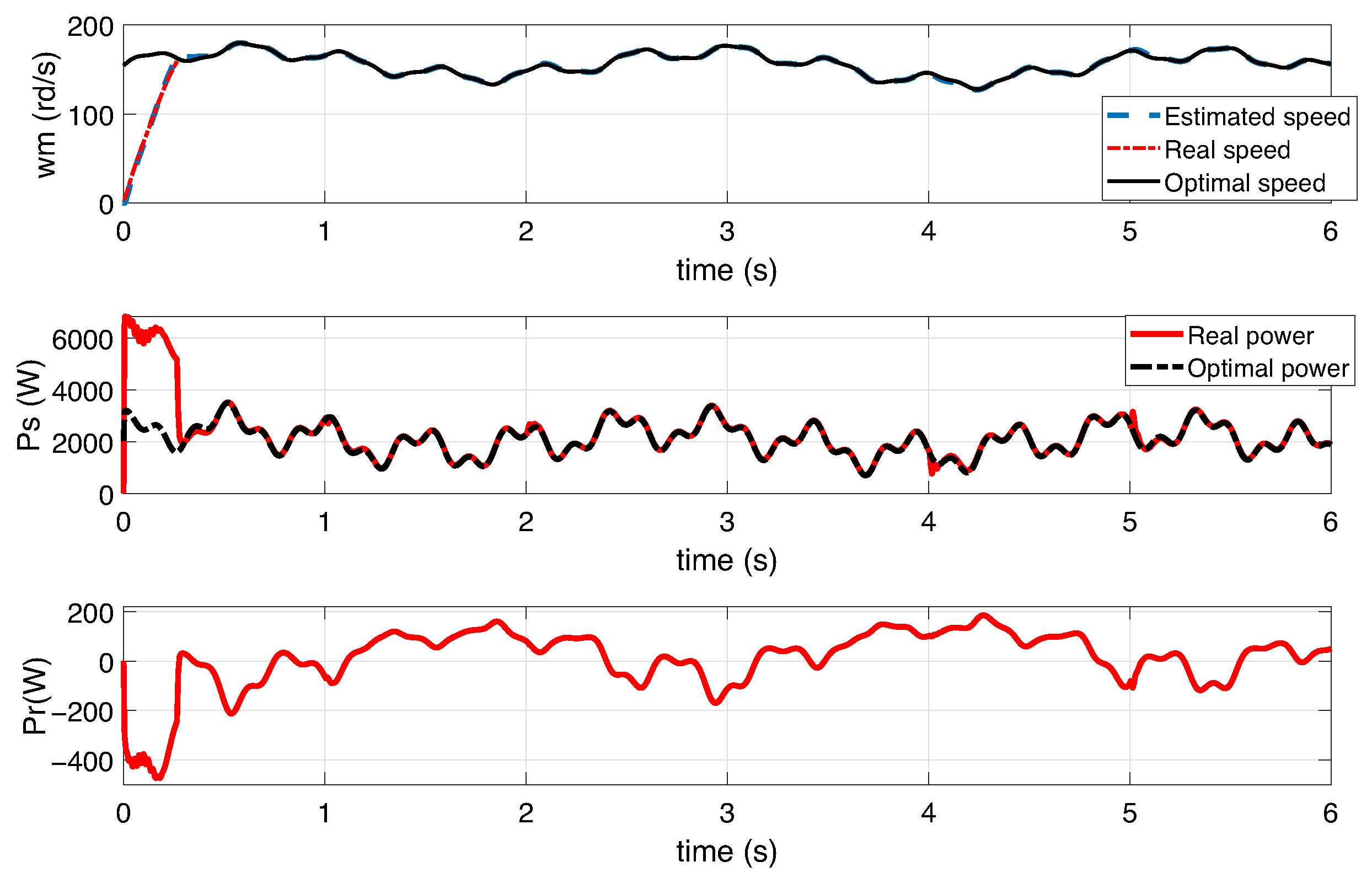
Figure 17 shows that the estimated generator speed follows the reference speed Ω m r e f = λ o p t V w G R . This forces the turbine to operate in the maximum power trajectory. In addition, there is a bilateral transfer of rotor active power between the rotor and the electrical grid, which depends on the synchronous speed of the generator ( 157 rds / s ) , allowing operation in hyper-synchronous and hypo-synchronous modes.
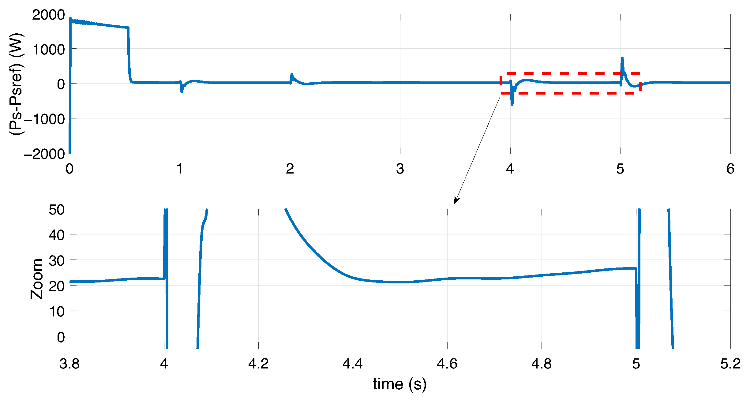
Figure 18 illustrates the tracking error of the maximum stator power, which remains below 30 rad/s during the ITSC fault interval application. This shows that the stator power closely converges to its maximum value, despite the presence of an inter-turn short-circuit (ITSC) fault. The results demonstrate that the effect of the fault is effectively compensated, allowing the wind turbine to continue operating under normal conditions.
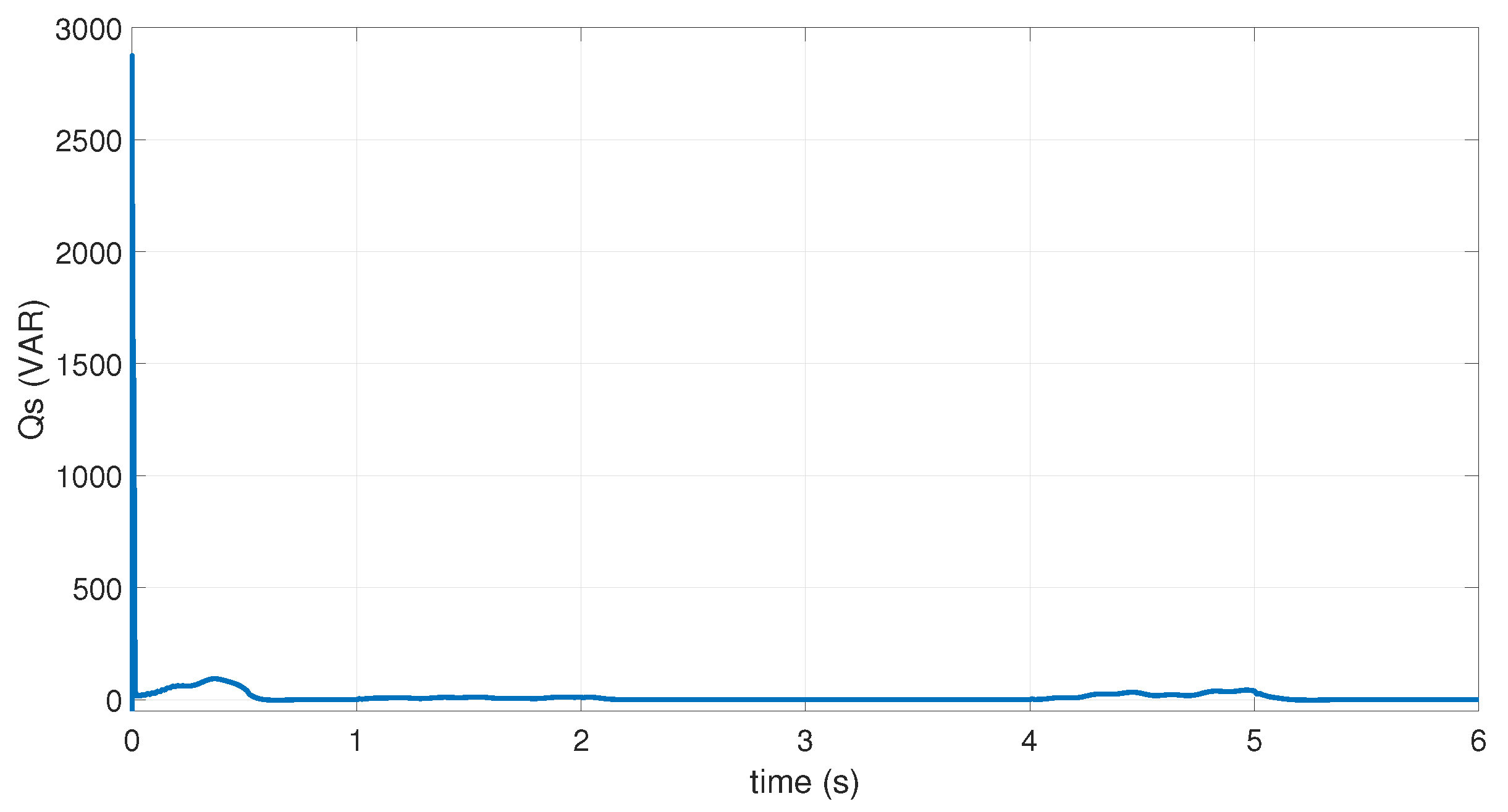
Figure 19 illustrates that the amplitude of the stator voltage is maintained constant, at the voltage grid ( 230 × 2 ) . Moreover, the reactive power of the stator is kept at zero as shown in Figure 20.
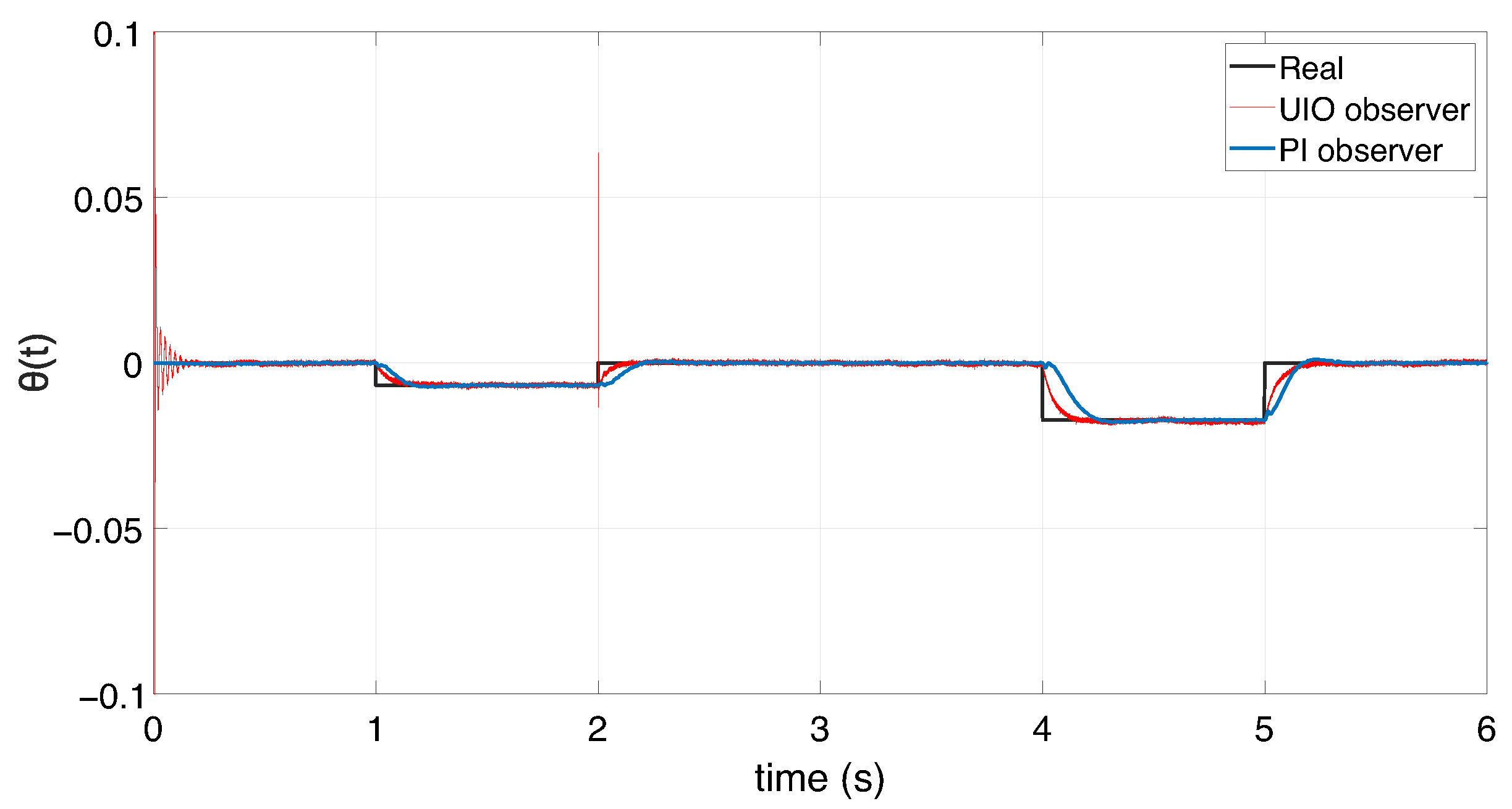
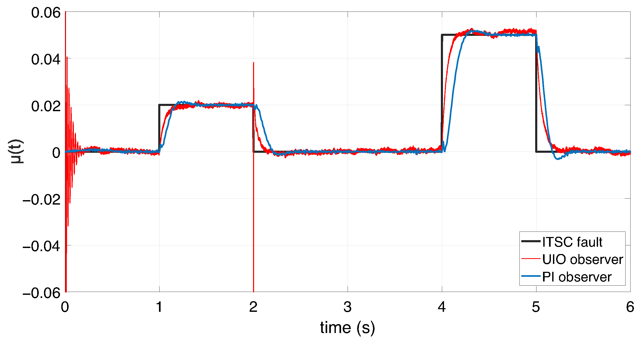
Figure 21 and Figure 22 show the unknown input θ ( t ) and the ITSC fault level μ ( t ) and their estimated curves using the PI observer and Unknown Input Observer with the presence of measurement noise. Table 4 presents a comparative study of the estimation performance of both the Unknown Input Observer (UIO) and the PI observer under 2 % and 5 % ITSC fault conditions.
  • For the 2 % ITSC fault, the UIO observer achieves a faster response time (0.215 s vs. 0.332 s) and a higher RMSE ( 0.852 % ) compared to the PI observer ( 0.435 % ), but no overshoot is recorded for the UIO. This suggests that the UIO reacts quickly but with slightly more steady-state error.
  • Under the 5 % ITSC fault, the UIO shows both faster response time (0.131 s vs. 0.221 s) and higher overshoot ( 5.4 % vs. 4 % ), while its RMSE ( 1.126 % ) is significantly greater than that of the PI observer ( 0.115 % ).
The proposed Fault Detection and Diagnosis (FDD) system successfully identifies and diagnoses both levels of the considered ITSC faults. The corresponding detection times are summarized in Table 5. As observed, an increase in fault level leads to a shorter detection time, indicating that the system responds more rapidly as the fault intensity increases. In addition, as shown in Figure 23, and for the same profile of ITSC fault illustrated in Figure 14, the proposed Fault Detection and Diagnosis (FDD) system successfully detects and identifies both levels of the considered ITSC faults. The corresponding detection times are summarized in Table 5. As observed, an increase in fault level leads to a shorter detection time, indicating that the system responds more rapidly as the fault intensity increases.

6. Conclusions

A fault-tolerant tracking control law for a wind turbine DFIG system subject to unknown inputs caused by an inter-turn short circuit in the stator winding is presented. The proposed method is an efficient solution to the problem of fault-tolerant trajectory tracking of ITSC faults affecting the stator winding in a wind turbine based on a Doubly Feed Induction Generator. Sufficient LMI conditions are developed to synthesize the controller and PI observer gains while minimizing the effect of the fault on the maximum power tracking performance. In addition, a diagnosis method based on a UIO observer is presented to detect and isolate an ITSC fault occurring in the stator winding over a wide range of generator speed variations. The simulation results show that by using the proposed observer, the developed FTC control scheme compensates the ITSC faults and ensures the stability of the closed-loop system.

Author Contributions

Modeling of a DFIG-based wind energy conversion system, Y.S., M.A. and S.M.; Fault-tolerant controller design subject to ITSC faults, Y.S., M.G., F.T. and D.M.; writing—original draft preparation, Y.S., M.A., M.G., S.M., F.T. and D.M.; writing—review and editing, Y.S., M.A., M.G., S.M., F.T. and D.M. All authors have read and agreed to the published version of the manuscript.

Funding

F. Tadeo received some financial support from Ministerio de Ciencia e Innovación (PID2021-123654OB-C31, MCIN/AEI/10.13039/501100011033) and FEDER, UE.

Data Availability Statement

The original contributions presented in this study are included in the article. Further inquiries can be directed to the corresponding author.

Acknowledgments

Yossra Sayahi was partially funded by an Erasmus+ KA107 Grant from EACEA, coordinated by the University of Valladolid, Spain. Tadeo is funded by MCIN/AEI/10.13039/501100011033 and European Union “NextGenerationEU/PRTR” as part of TED2021-129716BI00.

Conflicts of Interest

The authors declare no conflicts of interest.

Acronyms

FDDFault Detection and Diagnosis
FSFTCFuzzy Scheduler Fault-Tolerant Control
FTCFault-Tolerant Control
DFIGDoubly Fed Induction Generator
ITSCInter-Turn Short Circuit
LMILinear Matrix Inequalities
MPPTMaximum Power Point Tracking
PIOProportional Integral Observer
PMIOProportional Multiple Integral Observer
T-STakagi–Sugeno
UIOUnknown Input Observer (UIO)

References

  1. Vardhan, A.; Sinha, U. Control strategies and performance analysis of doubly fed induction generator for grid-connected wind energy conversion system. Electr. Eng. 2024, 106, 1203–1224. [Google Scholar] [CrossRef]
  2. Yaramasu, V.; Wu, B.; Sen, P.; Kouro, S.; Narimani, M. High-power wind energy conversion systems: State-of-the-art and emerging technologies. Proc. IEEE 2015, 103, 740–788. [Google Scholar] [CrossRef]
  3. Zhou, N.; Sun, F.; Wang, Q.; Meng, X. A flexible power control strategy for rotor-side converter of DFIG under unbalanced grid voltage sags. Int. J. Electr. Power Energy Syst. 2017, 90, 64–75. [Google Scholar] [CrossRef]
  4. Gao, Z.; Liu, X. An overview on fault diagnosis prognosis and resilient control for wind turbine systems. Processes 2021, 9, 300. [Google Scholar] [CrossRef]
  5. Bebars, A.; Eladl, A.; Abdulsalam, G.; Badran, E. Internal electrical fault detection techniques in DFIG-based wind turbines: A review. Prot. Control Mod. Power Syst. 2022, 7, 1–22. [Google Scholar] [CrossRef]
  6. Ma, K.; Soltani, M.; Hajizadeh, A.; Zhu, J.; Chen, Z. Active power optimisation for wind farms under generator inter-turn short-circuit fault. IET Renew. Power Gener. 2020, 14, 2079–2088. [Google Scholar] [CrossRef]
  7. Badihi, H.; Zhang, Y.; Hong, H. Wind turbine fault diagnosis and fault-tolerant torque load control against actuator faults. IEEE Trans. Control Syst. Technol. 2014, 23, 1351–1372. [Google Scholar] [CrossRef]
  8. Cheng, F.; Peng, Y.; Qu, L.; Qiao, W. Current-based fault detection and identification for wind turbine drivetrain gearboxes. IEEE Trans. Ind. Appl. 2016, 53, 878–887. [Google Scholar] [CrossRef]
  9. Afshar, M.; Abdi, S.; Mortazavizadeh, A.; Fajri, P.; Ebrahimi, M. A New Stator Winding Inter-Turn Short Circuit Fault Detection Method for Brushless Doubly Fed Induction Machine. In Proceedings of the 2020 IEEE 29th International Symposium on Industrial Electronics (ISIE), Delft, The Netherlands, 17–19 June 2020; IEEE: Piscataway, NJ, USA, 2020; pp. 223–228. [Google Scholar]
  10. Bilal, H.; Sambatra, E.; Heraud, N.; Razafimahenina, J.; Dyagileva, S. Detection of inter-turn short-circuit on a doubly fed induction machine with dq axis representation-application to different power levels. Prog. Electromagn. Res. B 2022, 95, 23–40. [Google Scholar] [CrossRef]
  11. Lu, Q.; Breikin, T.; Wang, H. Modelling and fault diagnosis of stator inter-turn short circuit in doubly fed induction generators. IFAC Proc. Vol. 2011, 44, 1013–1018. [Google Scholar] [CrossRef]
  12. Lu, Q.; Breikin, T. Fault detection for stator inter-turn short circuit in doubly fed induction generators using adaptive observers. Int. J. Adv. Mechatron. Syst. 2011, 3, 44–53. [Google Scholar] [CrossRef]
  13. Ma, K.; Zhu, J.; Soltani, M.; Hajizadeh, A.; Chen, Z. Inter-Turn Short-Circuit Fault Ride-Through for DFIG Wind Turbines. IFAC-PapersOnLine 2020, 53, 12757–12762. [Google Scholar] [CrossRef]
  14. Idrissi, I.; Bachtiri, R.E.; Chafouk, H.; Khanfara, M. Fault diagnosis of stator inter-turn short circuit in doubly fed induction generator of wind turbine. In Proceedings of the 2019 6th international conference on control, decision and information technologies (CoDIT), Paris, France, 23–26 April 2019; IEEE: Piscataway, NJ, USA, 2019; pp. 1313–1318. [Google Scholar]
  15. Mellah, H.; Arslan, S.; Sahraoui, H.; Hemsas, K. The effect of stator inter-turn short-circuit fault on dfig performance using fem. Eng. Technol. Appl. Sci. Res. 2022, 12, 8688–8693. [Google Scholar] [CrossRef]
  16. Rehman, A.; Chen, Y.; Zhao, Y.; Cheng, Y.; Zhao, Y.; Tanaka, T. Detection of rotor inter-turn short circuit fault in doubly-fed induction generator using FEM simulation. In Proceedings of the 2018 IEEE 2nd International Conference on Dielectrics (ICD), Budapest, Hungary, 1–5 July 2018; IEEE: Piscataway, NJ, USA, 2018; pp. 1–4. [Google Scholar]
  17. Rodríguez, J.; Hernández-De-León, H.; Marín, J.; Santiago, A.; Gómez, E.; Zapata, B.; Guzmán-Rabasa, J. Fault Diagnosis for Takagi-Sugeno Model Wind Turbine Pitch System. IEEE Access 2024, 12, 25296–25308. [Google Scholar] [CrossRef]
  18. Kamal, E.; Aitouche, A.; Abbes, D. Robust fuzzy scheduler fault tolerant control of wind energy systems subject to sensor and actuator faults. Int. J. Electr. Power Energy Syst. 2014, 55, 402–419. [Google Scholar] [CrossRef]
  19. Kamal, E.; Aitouche, A. Robust fault tolerant control of DFIG wind energy systems with unknown inputs. Renew. Energy 2013, 56, 2–15. [Google Scholar] [CrossRef]
  20. Sami, M.; Patton, R. An FTC approach to wind turbine power maximisation via TS fuzzy modelling and control. IFAC Proc. Vol. 2012, 45, 349–354. [Google Scholar] [CrossRef]
  21. Ouyessaad, H.; Chafouk, H.; Lefebvre, D. Doubly fed induction generator fault diagnosis using unknown input Takagi-Sugeno observer. In Proceedings of the 2013 International Conference on Control, Decision and Information Technologies (CoDIT), Hammamet, Tunisia, 6–8 May 2013; IEEE: Piscataway, NJ, USA, 2013; pp. 530–535. [Google Scholar]
  22. Sayahi, Y.; Allouche, M.; Ghamgui, M.; Moreau, S.; Mehdi, D. Contribution to the Sensors Faults Diagnosis of a Variable Speed Wind Turbine: Multimodel Approach. In Proceedings of the 2023 IEEE 11th International Conference on Systems and Control (ICSC), Sousse, Tunisia, 18–20 December 2023; IEEE: Piscataway, NJ, USA, 2023; pp. 427–432. [Google Scholar]
  23. Chen, Z.; Guerrero, J.M.; Blaabjerg, F. A review of the state of the art of power electronics for wind turbines. IEEE Trans. Power Electron. 2009, 24, 1859–1875. [Google Scholar] [CrossRef]
  24. Allouche, M.; Dahech, K.; Gaubert, J.P. Maximum Power Point Tracking control of a variable speed wind turbine via a TS fuzzy model-based approach. J. Intell. Fuzzy Syst. 2024, 46, 8529–8541. [Google Scholar]
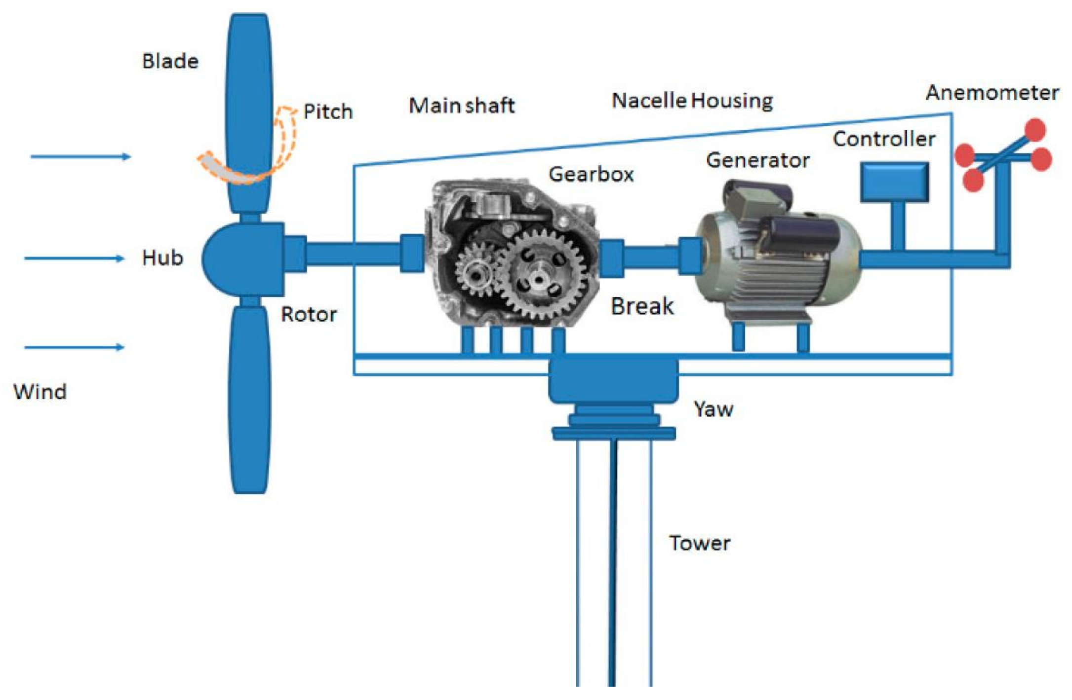
Figure 1. Wind turbine system [4].
Symmetry 17 01343 g001
Figure 2. Stator winding with ITSC fault in phase (b).
Symmetry 17 01343 g002
Figure 3. Block diagram of the indirect field-oriented control technique where the PI-blocks are the rotor current regulators, V s is the grid voltage phase, and g is the rotor speed slip.
Symmetry 17 01343 g003
Figure 4. Structure of the fault-tolerant trajectory tracking control.
Symmetry 17 01343 g004
Figure 5. The norm of d-q stator current error (in red) versus its threshold for fault detection (in blue).
Symmetry 17 01343 g005
Figure 6. Residuals of three phase stator currents.
Symmetry 17 01343 g006
Figure 7. Zoom on stator current residuals.
Symmetry 17 01343 g007
Figure 8. Generator speed under ITSC fault.
Symmetry 17 01343 g008
Figure 9. D-axis stator current.
Symmetry 17 01343 g009
Figure 10. Q-axis stator current.
Symmetry 17 01343 g010
Figure 11. Unknown input θ ( t ) and its estimation.
Symmetry 17 01343 g011
Figure 12. The ITSC fault level μ ( t ) and its estimation.
Symmetry 17 01343 g012
Figure 13. Wind speed profile.
Symmetry 17 01343 g013
Figure 14. Inter turn short-circuit fault profile.
Symmetry 17 01343 g014
Figure 15. D-axis stator current using the FTC controller.
Symmetry 17 01343 g015
Figure 16. Q-axis stator current using the FTC controller.
Symmetry 17 01343 g016
Figure 17. Generator speed, stator active power, and rotor active power.
Symmetry 17 01343 g017
Figure 18. Active stator power error.
Symmetry 17 01343 g018
Figure 19. The current variations (in the range [−15 A, 15 A]) and the voltage variations (range [−230 2 V, 230 2 V]) of the stator.
Symmetry 17 01343 g019
Figure 20. Stator reactive power curve.
Symmetry 17 01343 g020
Figure 21. Evolution of the unknown input θ ( t ) .
Symmetry 17 01343 g021
Figure 22. Fraction shape of the short-circuited stator winding μ ( t ) .
Symmetry 17 01343 g022
Figure 23. ITSC fault indicator.
Symmetry 17 01343 g023
Table 1. Specification of the wind power generator.
ParametersValues
R1.483 m
ρ 1.205  kg/m3
R s 1.94 Ω
R r 0.3 Ω
L s 201.51  mH
L r 19.1  mH
L m 59.71  mH
p 2
G 3.32
P n 3000 W
Table 2. Threshold current and detection time for a 2% ITSC fault.
Fault TypeThreshold λ (A)Detection Time (s)
2% ITSC fault0.30.091
Table 3. Error metrics for estimated state variables using UIO observer ( x 0 = 0 ).
State VariableRMSEMAEMax | X X ^ |
d-axis stator current i s d 0.14170.11300.7063
q-axis stator current i s q 0.14180.11310.6987
Generator speed0.15230.12140.8154
Table 4. Comparison of dynamic and estimation performance between UIO and PI observers for different ITSC fault levels.
Fault LevelUIO ObserverPI Observer
t r 5 % (s) OS (%)RMSE (%) t r 5 % (s) OS (%)RMSE (%)
2% ITSC fault0.2150.8520.33270.435
5% ITSC fault0.1315.41.1260.22140.115
Table 5. Detection times for different ITSC fault levels using a fixed threshold.
Fault TypeThreshold λ (A)Detection Time (s)
2% ITSC fault0.30.091
5% ITSC fault0.30.042
Disclaimer/Publisher’s Note: The statements, opinions and data contained in all publications are solely those of the individual author(s) and contributor(s) and not of MDPI and/or the editor(s). MDPI and/or the editor(s) disclaim responsibility for any injury to people or property resulting from any ideas, methods, instructions or products referred to in the content.