Article

Integrated I-ADALINE Neural Network and Selective Filtering Techniques for Improved Power Quality in Distorted Electrical Networks

1
Lee Kong Chian Faculty of Engineering and Science, Universiti Tunku Abdul Rahman, Kajang 43000, Selangor, Malaysia
2
Department of Electrical and Electronic Engineering, Faculty of Engineering, Universiti Putra Malaysia, Serdang 43400, Selangor, Malaysia
*
Authors to whom correspondence should be addressed.
Symmetry 2025, 17(8), 1337; https://doi.org/10.3390/sym17081337 (registering DOI)
Submission received: 7 June 2025 / Revised: 17 July 2025 / Accepted: 1 August 2025 / Published: 16 August 2025
(This article belongs to the Special Issue Symmetry/Asymmetry Studies in Modern Power Systems)

Abstract

Adaptive Linear Neuron (ADALINE) is a well-known neural network method that has been utilized for generating a reference current intended to regulate the operation of shunt-typed active harmonic filters (SAHFs). These filters are essential for improving power quality by mitigating harmonic disturbances and restoring current waveform symmetry in power systems. While the latest variant, Simplified ADALINE, offers notable advantages over its predecessors, such as a reduced complexity and faster learning speed, its performance has primarily been evaluated under stable grid conditions, leaving its performance under distorted environments largely unexplored. To address this gap, this work introduces two key modifications to the Simplified ADALINE framework: (1) the integration of a new phase-tracking algorithm based on the concept of orthogonality and selective filtering, and (2) transitioning from the direct current control (DCC) to an indirect current control (ICC) mechanism. Test environments featuring distorted grids and nonlinear rectifier loads are simulated in MATLAB/Simulink software to evaluate the performance of the proposed method against the existing Simplified ADALINE method. The key findings demonstrate that the proposed method effectively handled harmonic distortion and noise disturbance. As a result, the associated SAHF achieved an additional reduction in %THD (by 10.77–13.78%), a decrease in reactive power (by 58.3 VAR–67 VAR), and improved grid synchronization with a smaller phase shift (by 0.9–1.2°), while also maintaining proper waveform symmetry even in challenging grid conditions.

1. Introduction

The extensive utilization of nonlinear power electronics loads in power systems such as variable speed drives, uninterruptible power supplies, and energy-efficient lighting has made it increasingly difficult to manage harmonic disturbances [1,2]. These loads often disrupt the inherent symmetry of the power system, introducing unbalanced and distorted current waveforms. If left unmitigated, such asymmetry in current waveforms can cause a range of detrimental effects, such as increased heat losses, reduced system efficiency, voltage distortion, and potential damage to sensitive equipment [3,4,5].
The loss of waveform symmetry not only degrades the power quality but also negatively affects the reliability and stability of the power system operation. Therefore, preserving symmetry in both current and voltage waveforms is crucial to maintaining a balanced power flow and prevent equipment malfunction. Proactive mitigation strategies are necessary in order to address these disturbances and ensure the overall grid power quality. Recent studies highlight the role of shunt-type active harmonic filters (SAHFs), which utilize voltage source inverter topologies, as effective solutions for restoring waveform symmetry and mitigating harmonic distortion [3,6,7]. These filters help compensate for unbalanced and distorted currents, thereby improving both the quality and symmetry of the overall power system waveforms.
However, the effectiveness of an SAHF in mitigating power quality issues heavily depends on the accuracy and speed of its control strategies. The controller typically includes four core algorithms: harmonic currents extraction, DC-link voltage control, phase tracking, and current control algorithms [8,9,10]. Among these, the extraction of harmonic currents is considered the most critical. As the first algorithm executed within the controller, accurate extraction ensures that the harmonic components disrupting the symmetry of current waveforms are properly identified and targeted. Furthermore, the reference current must be precisely synchronized with the grid through the phase-tracking algorithm to maintain the symmetry and balance of the compensated current. Together, these processes enable the effective mitigation of waveform asymmetry and harmonic distortion, thereby preserving power quality [8,11,12].
Various studies have explored the techniques for harmonic currents extraction, as detailed in the literature [10,13]. Prominent techniques include the synchronous reference frame (SRF) [14,15] and instantaneous power theory [4,16] from the time-domain category, Fourier transform (FT) [17,18] from the frequency-domain category, and artificial neural network (ANN) [5,19,20] from the artificial intelligence (AI) category. Among these, the techniques based on the ANN concept are particularly noteworthy for their exceptional ability to provide rapid and accurate estimations of reference currents. These techniques are highly regarded for their self-adaptive capabilities, parallel processing power, and robust fault tolerance [19,21,22], making them a standout choice in dynamic and complex systems.
In the reference current generation, Adaptive Linear Neuron (ADALINE) [5,20,22,23] is a highly regarded architecture, recognized for its efficiency within ANN-based solutions. This approach operates by utilizing an appropriate weight adjustment mechanism, with the Widrow–Hoff (W–H) algorithm being particularly popular due to its simplicity and efficiency in minimizing the mean square error between the actual and predicted signals [24,25]. However, the conventional W–H algorithm faces challenges when attempting to learn the characteristics of multiple harmonic components, which necessitates more repetitive cycles and longer training times. To address these limitations, a modified W–H algorithm has been introduced. This modification directs the system to focus solely on learning the characteristics of the fundamental component, rather than the full spectrum of harmonic components, by fine-tuning the learning rate [21,25]. As a result, the modified algorithm significantly improves the speed and precision of the learning process, leading to fewer repetitive cycles and a considerable reduction in training time. However, both the conventional and modified W–H algorithms depend on conventional phase-tracking algorithms such as the zero-crossing detector (ZCD) [25] and phase-locked loop (PLL) [11,26] to align the phase of the generated reference current with the operating power system. This dependency has restricted their applicability, particularly to situations involving a stable supply voltage and steady-state operations.
A further investigation revealed that the modified W–H algorithm still contained redundant features and notable shortcomings, including a large mean square error and slow convergence, which negatively affected its overall performance. To address these issues, the algorithm was simplified to remove redundancy, resulting in the development of Simplified ADALINE (S-ADALINE) [21]. This revised version incorporates a new weight updating technique, called the fundamental active current (FAC), which helps to reduce the mean square error and further speed up the learning process, thereby enhancing the mitigation performance of the connected SAHF. Furthermore, a new phase-tracking algorithm, derived from the ADALINE concept, was integrated, effectively eliminating the dependence on ZCD and PLL [12,22]. With the implementation of the S-ADALINE algorithm, the associated SAHF now exhibits enhanced reliability, operating effectively under a stable supply voltage, and across both steady-state and dynamic conditions, even when subjected to varying load conditions.
Nevertheless, in practice, distortions in the utility grid are common and can compromise the reliability of the S-ADALINE algorithm, which was originally designed to operate under stable (sinusoidal and balanced) supply voltage conditions. As described in [12,22], the integrated ADALINE-based phase-tracking algorithm functions by converting the measured supply voltage directly into a unity form. Consequently, when the supply voltage is affected by distortions, the accuracy of the extracted phase information may degrade, resulting in improper phase synchronization and a failure to maintain waveform symmetry. Furthermore, an inherent drawback of the S-ADALINE algorithm is its tendency to generate a harmonic-based reference current, necessitating the gate pulses for the SAHF to be derived according to the direct current control (DCC) mechanism [27,28]. As reported in [8,29], the DCC mechanism lacks the ability to manage switching ripples caused by the operation of the SAHF, which further undermines the mitigation of asymmetrical and distorted waveforms. In contrast, the indirect current control (ICC) mechanism, which derives the gate pulses based on the evaluation of the supply current against a fundamental-based reference current [27,30], has been reported to address these shortcomings of the DCC mechanism by offering an improved ripple management and better preservation of waveform symmetry. Despite these advantages, no studies have yet explored integrating the S-ADALINE algorithm with the ICC mechanism to enhance harmonic mitigation and waveform symmetry.
With the increasing severity and unpredictability of harmonic disturbances, there is a pressing need to enhance the reliability and adaptability of the SAHF through adaptive AI approaches, in line with the recent advancements in artificial intelligence. Particularly, the development of improved reference current generation methods that maintain symmetry and effectively track fundamental components, even in highly distorted and dynamic grid conditions, is critical. In this work, the existing S-ADALINE algorithm is further developed by harnessing the strengths of the ICC mechanism. Additionally, the concept of orthogonality and selective filtering are integrated to enhance the overall reliability and performance of the system under such challenging grid environments. With these modifications, the resulting algorithm, termed Indirect ADALINE (I-ADALINE), offers the benefits of enhanced harmonic mitigation and reactive power compensation, along with reduced phase shift and improved accuracy in tracking the fundamental active current, thereby preserving the symmetry of current waveforms. The proposed I-ADALINE method is thoroughly tested under both steady-state and dynamic conditions, using a single-phase low-voltage distribution setup operating at 230 V and 50 Hz, with a distorted supply voltage and nonlinear rectifier loads to ensure a comprehensive performance evaluation.
The paper is organized as follows: Section 2 outlines the configuration of the power circuit and the controller for the single-phase SAHF system implemented in this work. In Section 3, the underlying principles of the proposed I-ADALINE algorithm are explained in detail. Section 4 provides a thorough analysis of the data, validating the design approach and demonstrating the effectiveness of the proposed algorithm. Finally, Section 5 summarizes the key outcomes and contributions of this work.

2. Single-Phase SAHF and Associated Control Algorithms

The architecture of the single-phase SAHF system along with the details of its controller is illustrated in Figure 1. In this work, a traditional voltage source inverter (VSI) is configured to function as an SAHF, while the harmonics are generated from rectifier-based circuits that supply either capacitive or inductive loads. The nonlinear behavior of the rectifier-based circuits will create harmonics in the load current i L ; i.e., the load current will contain both fundamental i F and harmonic i H components, thereby contaminating the supply current i S . Mathematically, their relationship can be expressed as follows:
i s   = i L   = i F   +   i H  
To resolve this concern, the SAHF is strategically positioned between the supply voltage v S and the load, linked at a common point (PCC). The controller then manages the SAHF to deliver mitigation current i m i g , which neutralizes all the harmonic components according to Expression (2). At the same time, for the proper operation, the SAHF is also controlled to draw a small amount of charging current i c h a r g i n g from the system to charge the DC-link capacitor. As shown, when the mitigation current i m i g is adjusted to match the harmonic components i H , the resulting supply current i S becomes purely the fundamental current i F   . This effectively restores the system to a clean, harmonic-free power quality.
i s   = i F   + i H i m i g + i c h a r g i n g
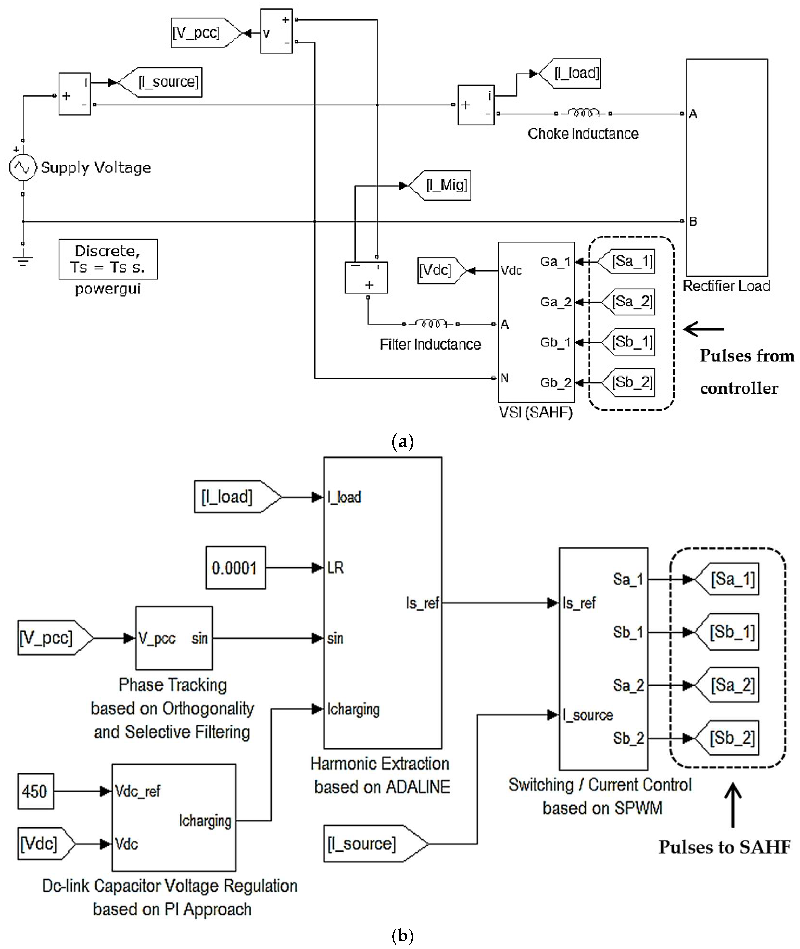
For the effective operation of the SAHF, the applied controller is structured with three primary modules, each responsible for generating reference current i S , r e f , regulating DC-link voltage V d c and delivering the gate pulses S , respectively. This work, however, primarily focuses on the generation of the reference current, introducing a method called Indirect ADALINE (I-ADALINE). Detailed information about this approach will be provided in the following section. Meanwhile, to regulate the DC-link voltage, a proportional-integral (PI) controller [16,26,31] is applied to estimate the amount of charging current I d c needed. For the generation of gate pulses, a method based on sinusoidal pulse-width modulation (SPWM) is adapted [8,28,32].

3. Reference Current Generation Based on I-ADALINE Concepts

This section describes the development of the proposed Indirect ADALINE (I-ADALINE) algorithm, starting with an in-depth analysis of the existing Simplified ADALINE (S-ADALINE) algorithm. Establishing this baseline provides a foundation for detailing the modifications performed, ultimately leading to the development of the proposed I-ADALINE algorithm. Lastly, the workflow is included to illustrate the structured organization and sequential execution of the algorithms implemented in this work, thereby facilitating a clearer understanding of the overall control strategy and the interactions between its components.
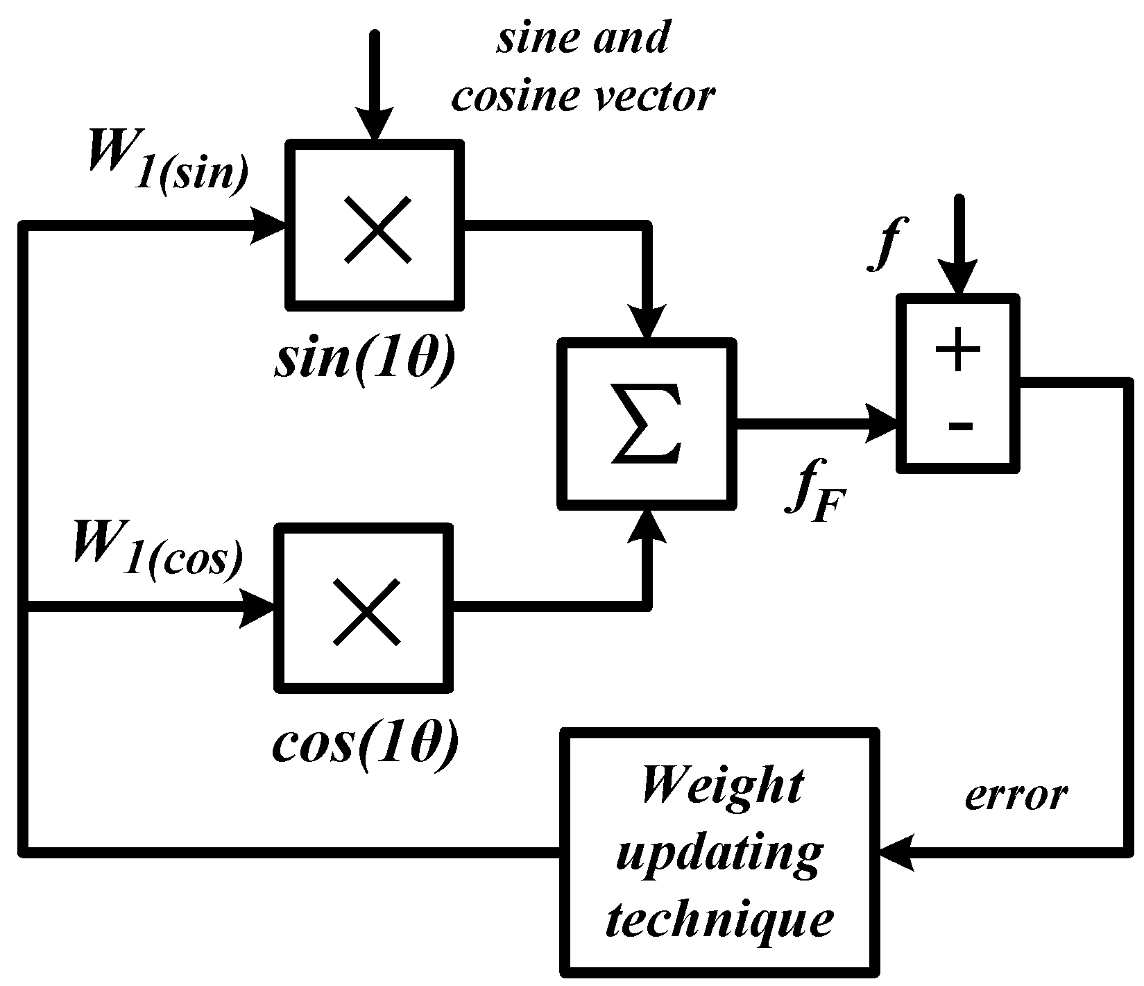
In general, the ADALINE algorithm with a conceptual model shown in Figure 2 is an approach to extract fundamental components of a periodic function. According to the Fourier series, a periodic function f can be represented as the sum of the sine and cosine functions. This representation allows any periodic signal to be approximated by a combination of these basis functions (sine and cosine waves) at different frequencies:
f ( θ ) = W 0 + n = 1,2 , 3 , N W n ( sin ) sin n θ + W n ( c o s ) cos n θ
where W 0 is the DC offset term, typically zero for AC signals, and W n ( s i n ) and W n ( c o s ) are the weight factors (amplitude) of the sine and cosine terms for each harmonic n , to a maximum number N. Meanwhile, variable θ is defined as θ = ω t + with angular frequency ω , time t , and phase offset .
However, instead of trying to learn the whole periodic function f , a standard ADALINE algorithm focuses only on the fundamental frequency component f F (the first harmonic, n = 1 ):
f F = W 1 ( sin ) sin 1 θ + W 1 ( c o s ) cos 1 θ ; n = 1
The goal of the ADALINE algorithm is to find the weights W 1 ( s i n ) and W 1 ( c o s ) that best represent this fundamental component using a weight-updating technique. During the learning process, in each iteration, the ADALINE algorithm adjusts these weights based on the error (the difference between the estimated signal and the actual signal). This process uses a learning rate to control how much the weights are updated at each step. By the end of the learning process, the ADALINE algorithm gives the correct weights for the fundamental frequency component, which can then be used to recreate the main part of the original signal.

3.1. Characteristics of the Simplified ADALINE (S-ADALINE) Algorithm

Figure 3 illustrates a block diagram representing the operational concept of the S-ADALINE algorithm. As has already been clearly described in [21], the algorithm incorporates a weight-updating technique, called the fundamental active current (FAC). This approach dynamically adjusts the weight factor of the sine term based on the magnitude of the fundamental active current within the power system. Unlike the standard ADALINE algorithm that updates both the sine and cosine terms, the S-ADALINE algorithm only updates the sine term because it is assumed that the fundamental active current has only a sine component. The overall learning process performed by the FAC updating technique can be simplified as follows:
I F ( u p d a t e d )   = I F ( p r e s e n t )   +   i L i F e s t   γ i sin θ
where I F   is the magnitude of the fundamental active current, i L is the measured load current, i F e s t is the estimated fundamental active current, γ i is the learning rate, and sin θ is the synchronization phase delivered by the phase-tracking algorithm.
In each iteration, i L will be compared with i F e s t and the resulted error e i will be processed to update magnitude I F   which will then be applied in the next loop. However, the measured load current i L contains harmonic components which cannot be fully described by a single sine component; thus, the error generated will be large. To handle this issue, a learning rate γ i of 0.0001 is required [21]. Over successive iterations, the estimated i F e s t progressively aligns with the profile of the fundamental active current. Using the updated I F   , along with the synchronization phase, the charging current I c h a r g i n g , and the measured load current i L , a harmonic-based reference current i H r e f   can be derived as shown in Expression (6). This harmonic-based reference current necessitates the gate pulses S to be derived based on the direct current control (DCC) mechanism, which requires measuring the actual mitigation current i m i g .
i H r e f   = ( I F   I c h a r g i n g   ) sin θ i L
On the other hand, to support the generation of the reference current, a phase-tracking algorithm based on the ADALINE concept is adopted. The complete operating principle of this algorithm has already been clearly described in [12,22]. In brief, the ADALINE-based phase-tracking algorithm utilizes a modified online W–H algorithm with a learning rate γ v of 0.01 to incrementally update two weight factors V F s i n (sine term) and V F c o s (cosine term), which represent the magnitude factor V F   of the supply voltage v s . The updating process can be summarized as follows:
V F ( u p d a t e d )   = V F ( p r e s e n t )   + γ v e v   P P T P
V F   = V F s i n V F c o s
P = sin 1 θ cos 1 θ
P T P = sin 1 θ cos 1 θ sin 1 θ cos 1 θ = 1
e v   = v S v F e s t
where e v   is the resulting error, P is the phase factor containing the fundamental sine ( sin 1 θ ) and cosine ( cos 1 θ ) terms of the supply voltage, and v F e s t is the estimated fundamental voltage. Together, Expression (7) can be finalized as follows:
V F ( u p d a t e d )   = V F ( p r e s e n t )   + 0.01   ( v S v F e s t ) sin 1 θ cos 1 θ
Eventually, the effective magnitude of the fundamental voltage can be obtained using Expression (13). Finally, the synchronization phase sin θ of the operating system is extracted by directly taking the unity representation of the supply voltage, according to Expression (14).
V F ( m a g ) = V F s i n 2 + V F c o s 2
sin θ = v s   V F ( m a g )
As can be observed from Expression (14), the measured supply voltage v s   is directly applied to establish the synchronization phase without pre-filtering to remove any potential distortions in the utility grid. Hence, any distortions in the grid can disrupt the accurate determination of the synchronization phase, leading to a misalignment of the mitigating current injected by the SAHF. Resolving this misalignment is crucial to ensuring a stable and reliable system operation.

3.2. Proposed Modifications

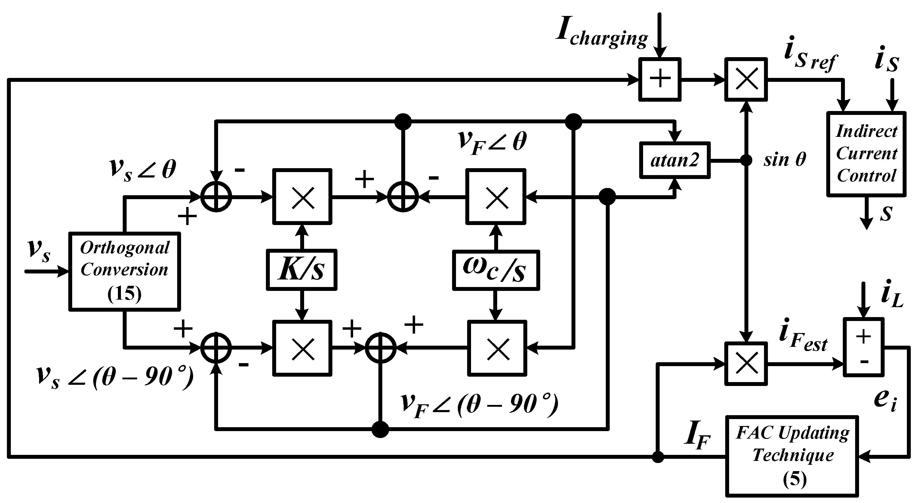
This work proposes two key modifications to the existing S-ADALINE algorithm, resulting in the development of the I-ADALINE algorithm as presented in Figure 4. First, a new phase-tracking algorithm which utilizes orthogonality and the selective filtering concept is integrated, replacing the previous dependency of the ADALINE-based phase-tracking algorithm. This approach leverages the orthogonal properties of the signal components to enable the effective pre-filtering of unwanted disturbances, which results in a more reliable phase estimation under challenging environments. In operation, assuming the supply voltage measured from the utility grid is represented in the time-domain as v s ( t ) =   V   s i n   ( ω t ) , two orthogonal periodic signals can be generated by delaying the measured v s ( t ) by a quarter of its period T to create a phase-shifted version of the signal. Mathematically, the following relationship holds:
v s     θ v s     θ 90 ° = v s ( t ) v s ( t T 4 ) = V   s i n   ( ω t ) V   s i n   ω t π 2 = V   s i n   ( ω t )   V   c o s   ( ω t )
where v s     θ and v s     θ 90 ° represent two orthogonal periodic signals of the measured supply voltage.
A selective filter is then applied to extract the fundamental components from these orthogonal signals. To obtain the transfer function of the selective filter, the integration process of the input orthogonal periodic signals needs to be studied as follows:
C α β ( t ) = e j ω c t e j ω c t R α β ( t ) d t .
where R α β t and C α β t are used to represent the input and output orthogonal signals of the integration process with angular frequency ω c . Next, by applying the Laplace transformation to convert the expression from the time-domain to the s-domain, and by presenting them as a ratio of the output to input, the resulting transfer function H ( s ) is obtained.
H ( s ) = C α β s R α β s = C α s + j C β s R α s + j R β s = s + j ω c   s 2 + ω c 2
To enable the adjustment of the selective filter’s performance, a parameter known as selectivity factor K is introduced to the transfer function, which is reformulated as Expressions (18) and (19). It is important to note that a smaller value of K enhances the filtering selectivity but reduces the convergence speed, whereas a larger value improves the convergence speed at the expense of selectivity.
C α s + j C β s R α s + j R β s = K ( s + K ) + j ω c   ( s + K ) 2 + ω c 2
C α s + j C β s = K s + K   s + K 2 + ω c 2 + j ω c   s + K 2 + ω c 2 R α s + j R β s
Next, by equating the real and imaginary sections, the following expressions can be obtained:
C α s = K s + K   s + K 2 + ω c 2 R α s K ω c   s + K 2 + ω c 2 R β s
C β s = K s + K   s + K 2 + ω c 2 R β s + K ω c   s + K 2 + ω c 2 R α s
Finally, by solving Expressions (20) and (21) simultaneously, the transfer function of the selective filter can be simplified as follows.
C α s = K s R α s C α s ω c s C β s
C β s = K s R β s C β s + ω c s C α s
Here, to suit the model applied in this work for extracting the fundamental components from the supply voltage, the output orthogonal signal C α s is replaced with v F     θ and C β s is replaced with v F     θ 90 ° , while the input orthogonal signal R α s is replaced with v s     θ and R β s is replaced with v s     θ 90 ° . As a result, the final transfer function of the selective filter applied in this work can be summarized as follows:
v F     θ = K s v s     θ v F     θ ω c   v F     ( θ 90 ° ) s
v F     θ 90 ° = K s v s     θ 90 ° v F     θ 90 ° + ω c   v F     θ s
where v F     θ and v F     θ 90 ° represent the two orthogonal periodic signals of the extracted fundamental components of the supply voltage with angular velocity ω c = 100 π rad/s, and K = 20 is the selectivity factor applied in this work. Finally, the synchronization phase sin θ is determined using the trigonometry function below:
sin θ = sin a t a n 2   v F     θ , v F     θ 90 °
In addition, to further enhance the mitigation performance via the minimization of switching ripples caused by the switching activities of the SAHF, the proposal involves transitioning from the DCC to the indirect current control (ICC) mechanism for the control of the SAHF. This transition requires adapting the existing S-ADALINE framework to align with the requirements of the ICC mechanism. Specifically, instead of generating a harmonic-based reference current, the modified algorithm will now produce a fundamental-based reference current i S r e f   , as outlined in Expression (27).
i S r e f   = ( I F   + I c h a r g i n g   ) sin θ
This fundamental-based reference current enables the generation of gate pulses S, which are derived from the measurement of the supply current i S   rather than the mitigation current i m i g . Unlike the DCC mechanism, the ICC mechanism operates by obtaining precise information about the switching ripples present in the supply current. Hence, any ripples contained in the supply current will be directly evaluated in the control system loop and eventually be minimized. In other words, this shift in approach improves the mitigation performance of the SAHF by directly addressing the limitations of the DCC mechanism.

3.3. Workflow of the Control Strategy

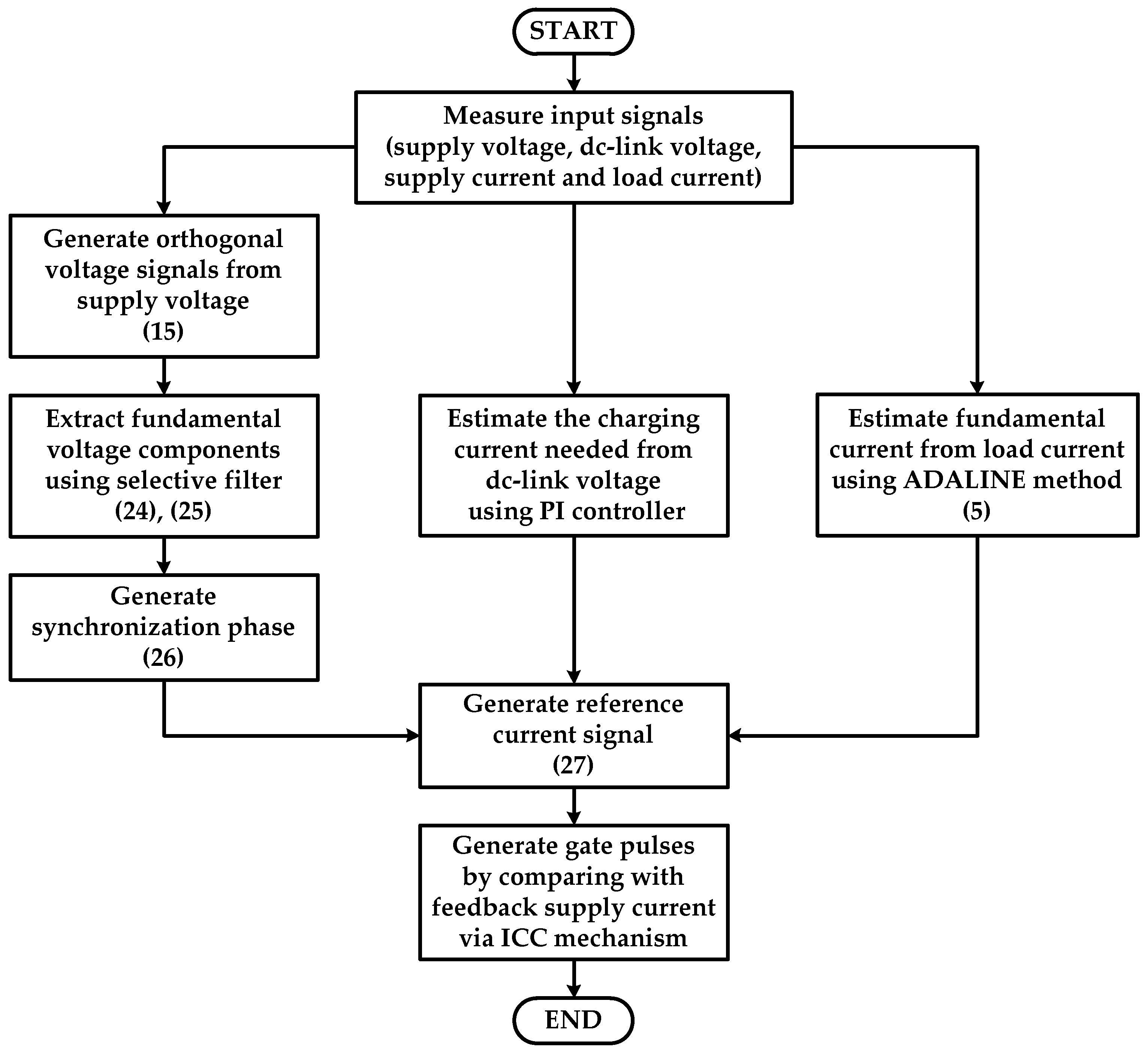
To facilitate a clear and structured understanding of how the various algorithms interact and operate sequentially in this work, an overview of the workflow is presented in Figure 5.
As a summary, the control algorithms operate according to the following sequences:
(i)
Measure the input signals (supply voltage v s , DC-link voltage V d c , supply current i S   , and load current i L );
(ii)
Generate orthogonal voltage signals v s     θ and v s     θ 90 ° from the measured supply voltage (Expression (15));
(iii)
Extract fundamental voltage components v F     θ and v F     θ 90 °   using a selective filter (Expressions (24) and (25));
(iv)
Generate synchronization phase sin θ (Expression (26));
(v)
Estimate fundamental current i F from the measured load current using the ADALINE method (Expression (5));
(vi)
Estimate the charging current I c h a r g i n g from the measured DC-link voltage using a PI controller;
(vii)
Generate reference current i S r e f   (Expression (27));
(viii)
Generate gate pulses S by comparing between the reference current and the measured supply current (feedback) via the ICC mechanism.

4. Results and Discussion

The single-phase SAHF system, along with its control algorithms and the newly proposed I-ADALINE method, is developed and simulated within the MATLAB/Simulink (R2012a) environment. The complete simulation model, which integrates the power circuit and control components, is illustrated in Figure 6. Meanwhile, the key simulation parameters used in the study are summarized in Table 1 for clarity.
In this setup, three types of supply voltages are applied, namely, sinusoidal, distorted, and distorted, with noise disturbance supply voltages. The sinusoidal supply voltage is set at a fundamental magnitude of 230 Vrms, operating at a frequency of 50 Hz. Meanwhile, the distorted supply voltage is characterized by a total harmonic distortion (THD) of 17.53%, indicating the presence of significant harmonic components. Finally, noise disturbance with a signal-to-noise ratio (SNR) of 20.89 dB is added to the distorted supply voltage, creating a challenging scenario that combines both harmonic distortion and noise interference. Two rectifier-based nonlinear loads are then connected to create a harmonic-rich environment. The first load, consisting of an uncontrolled bridge rectifier, a resistor and a capacitor, is named as the RC load. Meanwhile, the second load, which features a similar rectifier but with a resistor and an inductor, is named as the RL load.
To ensure a comprehensive evaluation, the proposed method is assessed under six scenarios, namely, Scenario A1 (sinusoidal supply and RC load), Scenario A2 (sinusoidal supply and RL load), Scenario B1 (distorted supply and RC load), Scenario B2 (distorted supply and RL load), Scenario C1 (distorted supply with noise and RC load), and Scenario C2 (distorted supply with noise and RL load). For benchmarking purposes, the existing S-ADALINE method is also re-simulated and tested under identical conditions. This allows for a direct comparison, highlighting the advantages of the proposed I-ADALINE method. In addition to these cases, a separate dynamic operation test is also conducted considering the load variation from RC to RL. Furthermore, a sensitivity analysis is performed to investigate the effect of the varying supply voltage total harmonic distortion (THD) and signal-to-noise ratio (SNR) on the performance of the proposed algorithm. These analyses aim to evaluate the robustness and adaptability of the I-ADALINE method under more challenging and realistic operating conditions, ensuring its practical applicability in dynamic power system environments.
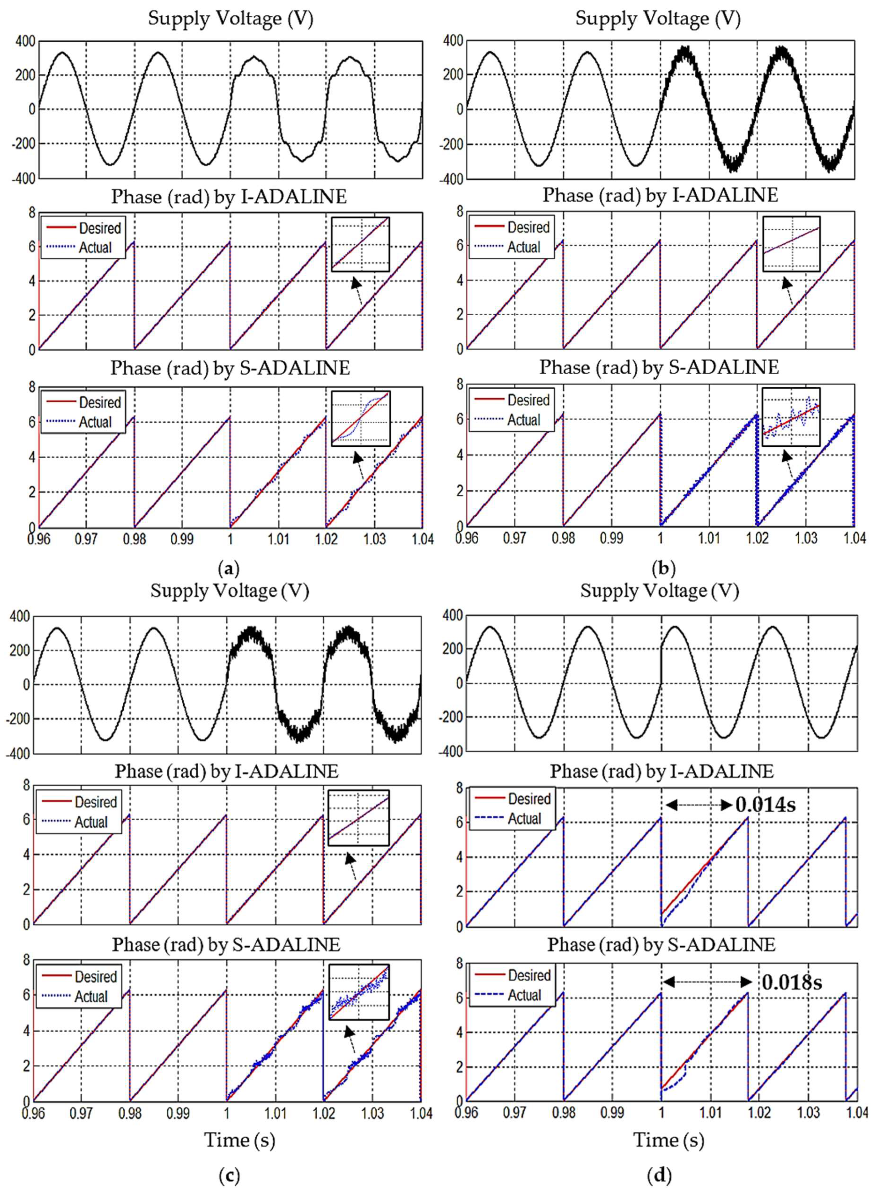
First, the phase-tracking performance of each method is evaluated under four distinct conditions: the presence of harmonic distortion, the presence of a 20.89 dB noise disturbance, the presence of both harmonics and noise disturbance, and a 40° phase jump. Each method is tested for its ability to accurately track the desired phase under these challenging conditions, offering valuable insights into their respective strengths and limitations when subjected to complex signal disturbances. The resulting phase information extracted by both methods is shown in Figure 7, with a detailed comparison highlighted in Table 2. As presented in Figure 7, both methods are revealed to be effective when dealing with the sinusoidal supply voltage. However, when the supply voltage is affected by harmonic distortion and noise (starting from time = 1 s), the phase information extracted by the existing S-ADALINE method can be observed to display undesired ripples and noise components, thereby undermining its reliability.
In contrast, despite the presence of harmonics and noise, the proposed I-ADALINE method is found to have effectively preserved the correct phase information, remaining free from any ripples or noise components. Moreover, when the supply voltage experiences a sudden phase jump of 40°, the proposed I-ADALINE method is observed to demonstrate superior performance by achieving a recovery time of 0.014 s. In comparison, the existing S-ADALINE method takes 0.018 s, making the proposed I-ADALINE method 0.004 s faster.
Based on this evaluation, it can be concluded that the proposed I-ADALINE method outperforms the existing S-ADALINE method in both phase-tracking accuracy and recovery speed. It offers high adaptability by maintaining accurate phase tracking even when the supply voltage is influenced by harmonic distortion and/or noise, while also providing a faster recovery time. This makes the proposed I-ADALINE method highly reliable in real-world applications, where disturbances are common. In contrast, the existing S-ADALINE method is constrained to operate only in disturbance-free environments and exhibits a slower performance with a longer recovery time when subjected to a phase shift.
Next, the proposed I-ADALINE method is evaluated across the six specified scenarios to determine its effectiveness in improving the mitigation performance of the SAHF, with outcomes directly compared to those of the existing S-ADALINE method. Figure 8, Figure 9 and Figure 10 present the waveforms obtained from this evaluation, while Table 3 provides a detailed comparison to facilitate a comprehensive interpretation of the findings.
From Figure 8, the sinusoidal waveform of all supply currents and their in-phase alignment with the supply voltage clearly demonstrate that both methods successfully directed the connected SAHF to restore waveform symmetry through effective harmonic mitigation and reactive power compensation under Scenarios A1 and A2. As recorded in Table 3, both methods reduced the supply current THD value to below 5%, thereby complying with the IEEE 519 standard [33,34], and ensured a near-unity power factor by minimizing the reactive power. This contributes to maintaining a symmetrical power flow between the supply and the load. Meanwhile, in terms of fundamental current tracking, both methods demonstrated comparable accuracy, achieving 98.92% and 95.17% in Scenarios A1 and A2, respectively. However, due to the improved switching ripple reduction in the proposed I-ADALINE method enabled by the ICC mechanism, it achieved slightly better waveform symmetry, with an additional THD reduction of 0.06% and 0.03% in Scenarios A1 and A2, respectively. These results highlight the ability of the proposed method to enhance signal symmetry under sinusoidal operating conditions.
On the other hand, Figure 9 clearly shows that the SAHF integrated with the existing S-ADALINE method failed to restore the sinusoidal symmetrical shape of the supply current in both Scenarios B1 and B2. As reported in Table 3, the THD values obtained are 14.41% and 14.45%, respectively, both exceeding the 5% limit specified in the IEEE 519 standard [33,34]. This elevated distortion reflects a persistent asymmetry in the current waveform. Moreover, the existing method is also found to cause a larger phase shift (1.4° in Scenario B1 and 1.0° in Scenario B2) and increased reactive power (73.6 VAR in Scenario B1 and 76.7 VAR in Scenario B2), which collectively degrade the power factor to 0.989. Next, the fundamental current tracking accuracy is also observed to be lower, with values of 95.44% and 98.44% in Scenarios B1 and B2, respectively.
In contrast, integrating the proposed I-ADALINE method enabled the connected SAHF to consistently preserve the sinusoidal and symmetrical shape of the supply current under the same distorted conditions. Specifically, the proposed method significantly reduces the THD values to 3.64% and 2.81% in Scenarios B1 and B2, respectively, restoring waveform symmetry and improving the power quality. Moreover, the proposed method also achieves substantially smaller phase shifts (0.2° in Scenario B1 and 0.1° in Scenario B2) and reactive power (10.4 VAR in Scenario B1 and 11.1 VAR in Scenario B2), thereby enhancing the power factor to 0.999 and promoting a more symmetrical power exchange. The fundamental current tracking accuracy has also improved, reaching 98.38% and 98.63% for Scenarios B1 and B2, respectively, which further confirms the effectiveness of the proposed method in maintaining waveform symmetry under distorted supply conditions.
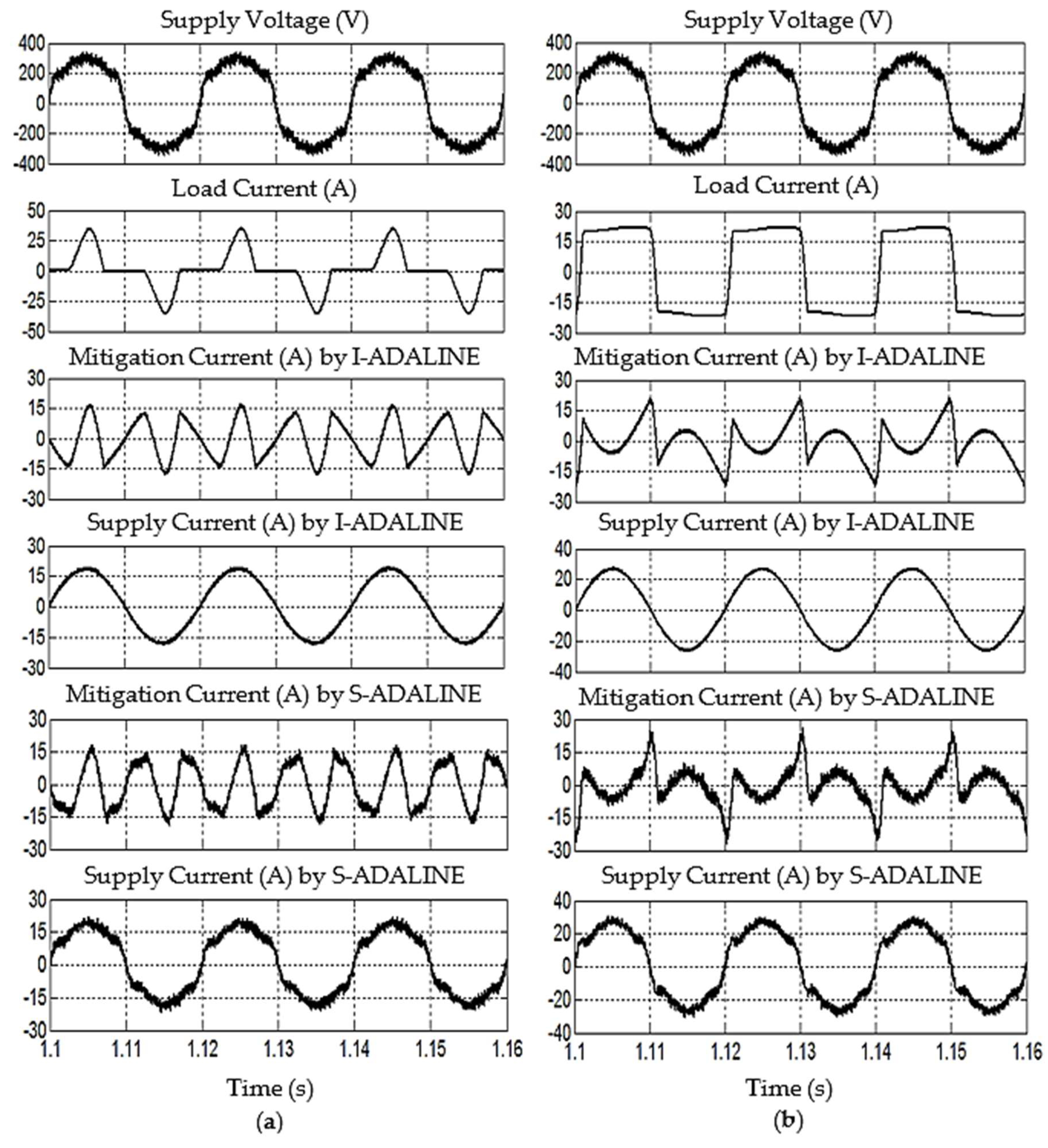
Finally, under the additional influence of noise, as can be observed from Figure 10 and Figure 11, the SAHF integrated with the existing S-ADALINE method again failed to restore the sinusoidal and symmetrical shape of the supply current in both Scenarios C1 and C2. This resulted in higher THD values of 15.77% and 16.55%, respectively, indicating persistent waveform asymmetry. Additionally, a larger phase shift (1.2° in Scenario C1 and 1.0° in Scenario C2) and increased reactive power (68.5 VAR in Scenario C1 and 78.5 VAR in Scenario C2) are also observed from the existing method, causing the power factor to degrade further to 0.987 and 0.986, respectively. More importantly, the added impact of noise has led to the lowest fundamental current tracking accuracy of 92.54% and 94.67% for Scenarios C1 and C2, respectively.
In contrast, the proposed I-ADALINE method enabled the connected SAHF to consistently maintain the sinusoidal and symmetrical shape of the supply current despite the presence of noise. The recorded THD values are significantly reduced to 3.71% and 2.77% for Scenarios C1 and C2, respectively, effectively restoring waveform symmetry and improving the power quality. Furthermore, the proposed method consistently achieved smaller phase shifts (0.2° in Scenario C1 and 0.1° in Scenario C2) and a lower reactive power (10.2 VAR in Scenario C1 and 11.5 VAR in Scenario C2), once again resulting in an improved power factor of 0.999. The fundamental current tracking accuracy is also substantially enhanced, reaching 98.38% and 98.63% for Scenarios C1 and C2, further demonstrating the robustness of the I-ADALINE method in preserving waveform symmetry under noisy and distorted conditions.
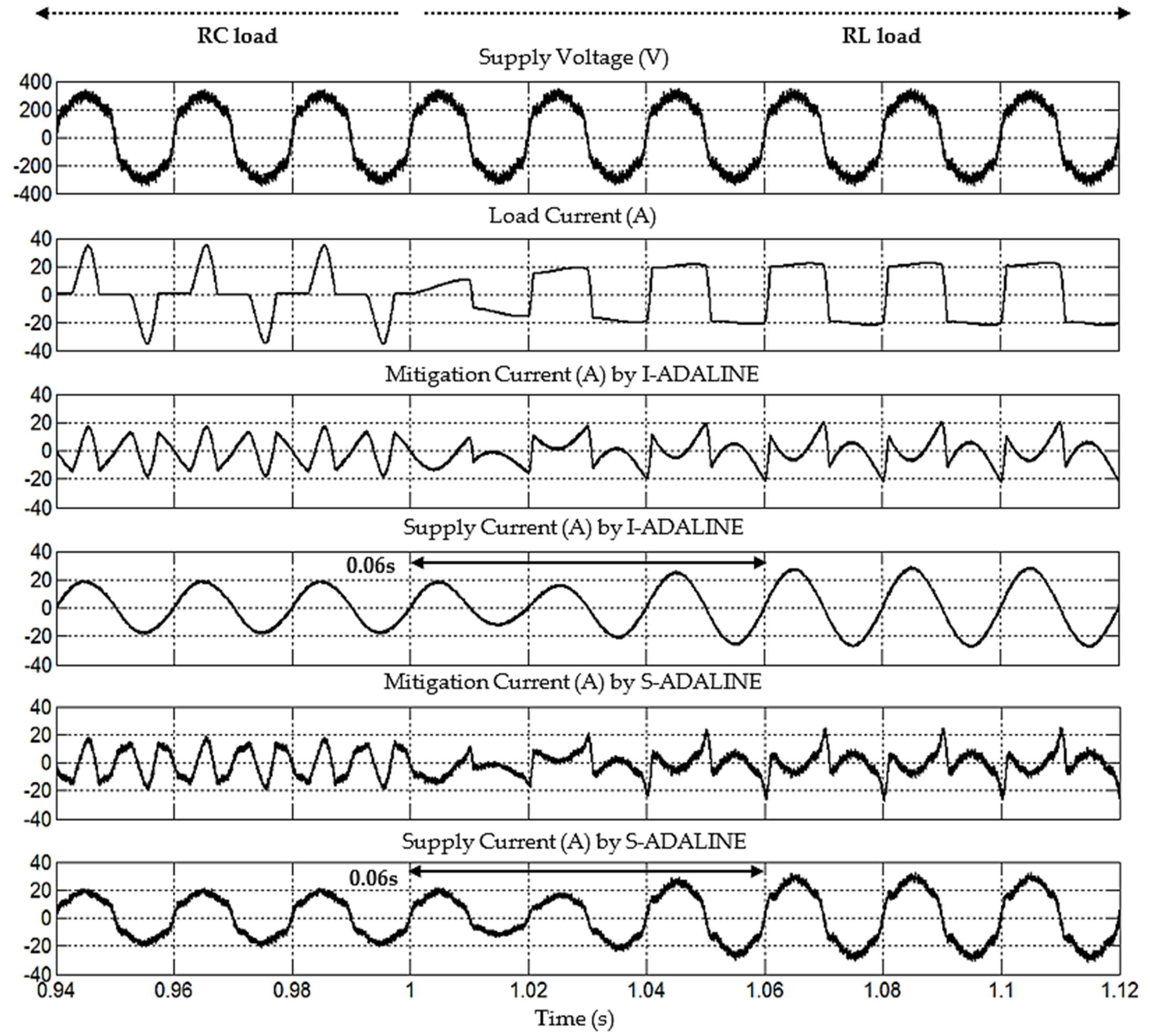
In addition to steady-state performance, a dynamic load test is carried out to evaluate the system behavior under varying load conditions, specifically involving a transition from the RC to RL load and a distorted supply with noise disturbance, as illustrated in Figure 12. As observed, following the load change at time = 1 s, both the I-ADALINE and S-ADALINE methods exhibit comparable dynamic responses, with recovery times within 0.06 s. This similarity is anticipated, as both methods utilize the same FAC updating technique and learning rate within their ADALINE frameworks. However, due to the incorporation of selective filtering and the ICC mechanism in the proposed I-ADALINE method, the quality of the mitigated supply current is significantly enhanced, exhibiting a continuous, sinusoidal, and symmetrical waveform with minimal distortion. In contrast, the output from the S-ADALINE method remains distorted and shows a significant level of noise. This demonstrates that the proposed enhancements in the I-ADALINE method effectively improve the output quality without compromising dynamic performance.
From the comparative analysis performed, the proposed I-ADALINE method demonstrates clear advantages over the existing S-ADALINE method. The key improvements, as highlighted in Table 4, include a significant reduction in %THD (by 10.77–13.78%), a decrease in phase shift (by 0.9–1.2°), and a substantial drop in reactive power (by 58.3 VAR–67 VAR). These enhancements contribute to an increase in power factor values (by 0.010 to 0.013). Furthermore, the proposed method also achieves better fundamental current tracking which improved the accuracy (by 0.19% to 5.84%). Importantly, the I-ADALINE method consistently restores and maintains the sinusoidal and symmetrical shape of the supply current waveform, effectively mitigating the harmonic distortion and reactive power caused by various nonlinear loads, even when the supply is affected by severe harmonic distortion and noise disturbances. This results in a superior overall power quality and more symmetrical power flow between the supply and load, demonstrating the robustness and effectiveness of the proposed method in challenging operating environments.
To further support the findings from the initial comparative analysis, a sensitivity study is added to examine how variations in the supply voltage total harmonic distortion (THD) and signal-to-noise ratio (SNR) influence the performance of the proposed I-ADALINE method. In this study, the supply voltage THD is adjusted between 5.16% and 25.16%, while the SNR is adjusted between 10.24 dB and 30.24 dB. The performance metrics evaluated include the THD of the supply current, the phase shift, and the power factor of the system. The results summarized in Table 5 and Table 6 provide strong evidence of the superior performance of the proposed I-ADALINE method compared to the existing S-ADALINE approach, under a range of operating conditions.
One of the key observations from the study is that, as the THD in the supply voltage increases, there is a corresponding increase in the THD of the supply current. This trend is observed for both the RC and RL load conditions and is consistent with the behavior expected in power systems where harmonic-rich voltage sources tend to propagate distortion into the load current. Despite this natural increase in current distortion, the I-ADALINE method demonstrates a remarkable ability to contain and mitigate its effects. For example, in the case of the RC load, the supply current THD with the I-ADALINE method increases only slightly from 3.26% to 4.03% when the supply voltage THD increases from 5.16% to 25.16%. In contrast, the S-ADALINE method shows a much steeper rise in the current THD, from 5.53% to 19.17% over the same range. A similar pattern is evident with the RL load, where the I-ADALINE method keeps the current THD below 3.31% even at the highest distortion level, while the current THD escalates to 19.71% for the S-ADALINE method. These results clearly demonstrate that, while current distortion does increase with worsening voltage conditions, the proposed I-ADALINE method is significantly more effective at suppressing this distortion compared to the existing S-ADALINE method.
In addition to the improved harmonic mitigation, the proposed I-ADALINE method also shows superior performance in controlling the phase shift between the voltage and current, which is critical for maintaining synchronization and minimizing reactive power flow. Across all test conditions, the I-ADALINE method maintains the phase shift within a narrow range, typically below 0.3°, while the S-ADALINE method experiences larger deviations, especially under high distortion or noise conditions. This phase accuracy contributes to the near-unity power factor achieved by the I-ADALINE method, which remains at 0.999 in all cases. In contrast, the power factor associated with the S-ADALINE method degrades with increasing distortion, dropping to as low as 0.981 and 0.980 in the RC and RL load conditions, respectively.
Furthermore, the robustness of the I-ADALINE method under noise disturbances is evident from its stable performance across a wide range of SNRs, from 30.24 dB down to 10.24 dB. Even in the presence of significant noise, the supply current THD, phase shift, and power factor remain largely unaffected with the I-ADALINE method, indicating a strong adaptability and lower sensitivity to disturbances. On the other hand, the S-ADALINE method exhibits an obvious decline in performance under the same noise levels, indicating a greater sensitivity to disturbances.
As a summary, by utilizing the advantages of selective filtering and the ICC mechanism, the proposed I-ADALINE method has demonstrated clear and consistent superiority over the existing S-ADALINE method in mitigating the harmonic distortion, minimizing the phase shift, and maintaining the near-unity power factor under a wide range of supply voltage distortions and noise disturbances. Consequently, the proposed method reliably preserves the sinusoidal and symmetrical supply current waveforms, even under severe distortion and challenging operating conditions. This results in an enhanced power quality and more efficient energy transfer between the supply and load, making the approach a robust and dependable solution for modern power systems facing nonlinear and variable conditions.
Future work could explore the integration of the I-ADALINE method with other advanced machine-learning methods such as deep learning or reinforced learning to further enhance its performance in dynamic and complex systems. These AI-driven approaches offer promising capabilities for self-adaptation, real-time learning, and increased resilience against unpredictable disturbances, which are particularly valuable in dynamic and complex power systems. While this study has focused on enhancing the ADALINE-based approach, future work could include a comparative analysis between I-ADALINE and other neural network models such as artificial neural networks (ANNs), recurrent neural networks (RNNs), long short-term memory (LSTM) networks, convolutional neural networks (CNNs), or hybrid models. Each of these models exhibits unique strengths in handling nonlinearities and dynamic behavior. Benchmarking them against I-ADALINE would provide deeper insight into the relative advantages and help identify the most suitable architecture for specific power quality applications.
Additionally, the application of the proposed method could be further validated under real-world conditions involving a broader range of power quality disturbances. This includes scenarios with significant voltage distortion, supply frequency fluctuations, dynamic load behaviors, and the intermittent nature of renewable energy sources. Evaluating the method under such diverse conditions would enhance its practical relevance and deployment readiness. The sensitivity analysis also represents an important area for future study. Investigating how variations in key system parameters and initial conditions affect the performance of the I-ADALINE method would provide critical insights into its robustness and scalability for real-world implementation.
Another promising research direction involves extending the I-ADALINE framework with diagnostic capabilities, such as the automatic classification and source identification of power quality disturbances. As modern power systems become increasingly populated with power electronic converters, electric vehicle chargers, and nonlinear industrial equipment, the ability to identify which specific consumer or load is responsible for the power quality degradation becomes essential. Such features would enable more targeted and effective mitigation strategies, allowing grid operators to proactively manage and maintain regulatory compliance in increasingly complex electrical networks.
Building on these directions, the most immediate and practical continuation of this work is the development of a laboratory-scale prototype that implements the I-ADALINE method within a physical power system environment. Such an experimental setup would facilitate the validation of the proposed approach under real-world operating conditions, accounting for factors such as electrical noise, hardware limitations, and unpredictable disturbances, which are often challenging to replicate accurately in simulation environments.
In summary, future research should focus on enhancing the I-ADALINE framework through advanced machine-learning integration, a comparative analysis with other neural models, sensitivity evaluation, and diagnostic capabilities such as disturbance classification. The immediate step is developing a laboratory-scale prototype to validate real-time performance under realistic conditions. These efforts will help bridge the gap between simulation and deployment, supporting the adoption of intelligent, adaptive solutions for modern power quality management.

5. Conclusions

This study proposes an approach called I-ADALINE, which aims to enhance synchronization and improve the mitigation performance of SAHF under challenging grid environments. It is basically achieved by incorporating an alternative phase-tracking approach that builds upon the concept of orthogonality and selective filtering, while also utilizing the benefits of the ICC mechanism. Together, these elements enable the method to address harmonic distortion, accurately generate the reference current, and preserve current waveform symmetry, which are crucial for maintaining the overall power quality. Extensive simulation tests, which include scenarios of highly nonlinear loads, voltage distortions, and noise disturbances, were conducted to validate the operational concept and assess the performance of the proposed method.
A comparative analysis against the existing S-ADALINE method demonstrates that the proposed I-ADALINE method offers notable improvements in both the phase-tracking accuracy and adaptability. These advantages are particularly evident under adverse conditions such as harmonic distortion, noise disturbance, and phase jumps. More importantly, the I-ADALINE method is also revealed to deliver superior mitigation performance for hte SAHF, as evidenced by an additional reduction in %THD (by 10.77–13.78%), a further decrease in reactive power (by 58.3 VAR–67 VAR), improved grid synchronization with a smaller phase shift (by 0.9–1.2°), and an improvement in the tracking accuracy of the fundamental current (by 0.19–5.84%). These findings confirm the effectiveness of I-ADALINE in maintaining power quality and waveform symmetry under challenging grid environments.
However, it is important to note a few limitations of the proposed method. While it demonstrates reliable performance under distorted but frequency-stable conditions, its ability to maintain precise phase angle tracking under time-varying and highly dynamic grid frequency conditions remains limited. This highlights the need for further enhancements to improve its robustness against frequency fluctuations. Another limitation is that the performance can be affected by changes in system conditions and settings. For example, different loads or disturbances may require parameter adjustments to maintain optimal results, which was not fully studied in this work. The proposed method is particularly suited for industrial and commercial applications involving nonlinear loads such as variable speed drives, rectifiers, and renewable energy interfacing, where the power quality is critical. It also shows promise for residential environments with the growing penetration of power electronics. Future work will focus on extending the I-ADALINE framework by incorporating advanced machine-learning techniques, developing diagnostic capabilities for disturbance classification and source identification, conducting sensitivity analyses, and progressing toward laboratory-scale prototyping. These efforts aim to bridge the gap between simulation and practical deployment, enhancing the adaptability and resilience in increasingly complex power systems.

Author Contributions

Conceptualization, Y.H.; methodology, Y.H. and K.W.C.; software, Y.H. and K.W.C.; validation, Y.H., K.W.C. and M.A.M.R.; formal analysis, Y.H.; investigation, Y.H. and K.W.C.; resources, Y.H., K.W.C. and M.A.M.R.; writing—original draft preparation, Y.H.; writing—review and editing, Y.H., K.W.C. and M.A.M.R.; supervision, M.A.M.R.; project administration, Y.H. and K.W.C.; funding acquisition, Y.H. and K.W.C. All authors have read and agreed to the published version of the manuscript.

Funding

This research was supported by the Ministry of Higher Education, Malaysia (MoHE), through the Fundamental Research Grant Scheme (FRGS/1/2024/TK08/UTAR/02/4).

Data Availability Statement

The data is contained within the article.

Conflicts of Interest

The authors declare no conflicts of interest.

Abbreviations

The following abbreviations are used in this manuscript:
ADALINEAdaptive linear neuron
ANNArtificial neural network
DCCDirect current control
FACFundamental active current
ICCIndirect current control
PCCPoint of common coupling
SAHFShunt-typed active harmonic filter
SNRSignal-to-noise ratio
THDTotal harmonic distortion
VSIVoltage source inverter

References

  1. Lumbreras, D.; Gálvez, E.; Collado, A.; Zaragoza, J. Trends in power quality, harmonic mitigation and standards for light and heavy industries: A review. Energies 2020, 13, 5792. [Google Scholar] [CrossRef]
  2. Smadi, I.A.; Albatran, S.; Alsyouf, M.A. Power quality improvement of a class of reduced device count inverter. Simul. Model. Pract. Theory 2019, 96, 101939. [Google Scholar] [CrossRef]
  3. Li, D.; Wang, T.; Pan, W.; Ding, X.; Gong, J. A comprehensive review of improving power quality using active power filters. Electr. Power Syst. Res. 2021, 199, 107389. [Google Scholar] [CrossRef]
  4. Imam, A.A.; Kumar, R.S.; Al-Turki, Y.A. Modeling and simulation of a pi controlled shunt active power filter for power quality enhancement based on p-q theory. Electronics 2020, 9, 637. [Google Scholar] [CrossRef]
  5. Asadi, Y.; Eskandari, M.; Mansouri, M.; Chaharmahali, S.; Moradi, M.H.; Tahriri, M.S. Adaptive neural network for a stabilizing shunt active power filter in distorted weak grids. Appl. Sci. 2022, 12, 8060. [Google Scholar] [CrossRef]
  6. Hasan, K.; Othman, M.M.; Meraj, S.T.; Mekhilef, S.; Abidin, A.F.B. Shunt active power filter based on savitzky-golay filter: Pragmatic modelling and performance validation. IEEE Trans. Power Electron. 2023, 38, 8838–8850. [Google Scholar] [CrossRef]
  7. Nour, A.M.M.; Helal, A.A. A voltage sensorless technique for a shunt active power filter adopting band pass filter under abnormal supply conditions. Electr. Power Syst. Res. 2025, 238, 111133. [Google Scholar] [CrossRef]
  8. Hoon, Y.; Radzi, M.A.M.; Hassan, M.K.; Mailah, N.F. Control algorithms of shunt active power filter for harmonics mitigation: A review. Energies 2017, 10, 2038. [Google Scholar] [CrossRef]
  9. Liang, X.; Andalib-Bin-Karim, C. Harmonics and mitigation techniques through advanced control in grid-connected renewable energy sources: A review. IEEE Trans. Ind. Appl. 2018, 54, 3100–3111. [Google Scholar] [CrossRef]
  10. Green, T.C.; Marks, J.H. Control techniques for active power filters. IEE Proc. Electr. Power Appl. 2005, 152, 369–381. [Google Scholar] [CrossRef]
  11. Qasim, M.; Kanjiya, P.; Khadkikar, V. Artificial-neural-network-based phase-locking scheme for active power filters. IEEE Trans. Ind. Electron. 2014, 61, 3857–3866. [Google Scholar] [CrossRef]
  12. Hoon, Y.; Radzi, M.A.M.; Zainuri, M.A.A.M.; Zawawi, M.A.M. Shunt active power filter: A review on phase synchronization control techniques. Electronics 2019, 8, 791. [Google Scholar] [CrossRef]
  13. Bhattacharya, A.; Chakraborty, C.; Bhattacharya, S. Shunt compensation. IEEE Ind. Electron. Mag. 2009, 3, 38–49. [Google Scholar] [CrossRef]
  14. Campos-Gaona, D.; Peña-Alzola, R.; Monroy-Morales, J.L.; Ordonez, M.; Anaya-Lara, O.; Leithead, W.E. Fast selective harmonic mitigation in multifunctional inverters using internal model controllers and synchronous reference frames. IEEE Trans. Ind. Electron. 2017, 64, 6338–6349. [Google Scholar] [CrossRef]
  15. Kumar, R.; Bansal, H.O.; Gautam, A.R.; Mahela, O.P.; Khan, B. Experimental investigations on particle swarm optimization based control algorithm for shunt active power filter to enhance electric power quality. IEEE Access 2022, 10, 54878–54890. [Google Scholar] [CrossRef]
  16. Ouchen, S.; Betka, A.; Gaubert, J.-P.; Abdeddaim, S. Simulation and real time implementation of predictive direct power control for three phase shunt active power filter using robust phase-locked loop. Simul. Model. Pract. Theory 2017, 78, 1–17. [Google Scholar] [CrossRef]
  17. Terriche, Y.; Guerrero, J.M.; Vasquez, J.C. Performance improvement of shunt active power filter based on non-linear least-square approach. Electr. Power Syst. Res. 2018, 160, 44–55. [Google Scholar] [CrossRef]
  18. Sozanski, K.; Szczesniak, P. Advanced control algorithm for three-phase shunt active power filter using sliding dft. Energies 2023, 16, 1453. [Google Scholar] [CrossRef]
  19. Iqbal, M.; Jawad, M.; Jaffery, M.H.; Akhtar, S.; Rafiq, M.N.; Qureshi, M.B. Neural networks based shunt hybrid active power filter for harmonic elimination. IEEE Access 2021, 9, 69913–69925. [Google Scholar] [CrossRef]
  20. Janpong, S.; Areerak, K.; Areerak, K. Harmonic detection for shunt active power filter using adaline neural network. Energies 2021, 14, 4351. [Google Scholar] [CrossRef]
  21. Zainuri, M.A.A.M.; Radzi, M.A.M.; Soh, A.C.; Mariun, N.; Rahim, N.A. Simplified adaptive linear neuron harmonics extraction algorithm for dynamic performance of shunt active power filter. Int. Rev. Model. Simul. 2016, 9, 144–154. [Google Scholar]
  22. Rahman, N.F.A.; Radzi, M.A.M.; Soh, A.C.; Mariun, N.; Rahim, N.A. Dual function of unified adaptive linear neurons based fundamental component extraction algorithm for shunt active power filter operation. Int. Rev. Electr. Eng. 2015, 10, 544–552. [Google Scholar]
  23. Karthikeyan, M.; Sharmilee, K.; Balasubramaniam, P.M.; Prakash, N.B.; Babu, M.R.; Subramaniyaswamy, V.; Sudhakar, S. Design and implementation of ann-based sapf approach for current harmonics mitigation in industrial power systems. Microprocess. Microsyst. 2020, 77, 103194. [Google Scholar] [CrossRef]
  24. Merabet, L.; Saad, S.; Abdeslam, D.O.; Merckle, J. Direct neural method for harmonic currents estimation using adaptive linear element. Electr. Power Syst. Res. 2017, 152, 61–70. [Google Scholar] [CrossRef]
  25. Radzi, M.A.M.; Rahim, N.A. Neural network and bandless hysteresis approach to control switched capacitor active power filter for reduction of harmonics. IEEE Trans. Ind. Electron. 2009, 56, 1477–1484. [Google Scholar] [CrossRef]
  26. Demirdelen, T.; Kayaalp, R.İ.; Tumay, M. Simulation modelling and analysis of modular cascaded multilevel converter based shunt hybrid active power filter for large scale photovoltaic system interconnection. Simul. Model. Pract. Theory 2017, 71, 27–44. [Google Scholar] [CrossRef]
  27. Adel, M.; Kandil, T. Assessment of direct and indirect current control techniques applied to active power filters. Recent Adv. Electr. Electron. Eng. 2020, 13, 1256–1265. [Google Scholar] [CrossRef]
  28. Sao, J.K.; Patidar, R.D.; Swain, S.D. Analysis of direct and indirect current control techniques in p-q theory based shunt active power filter. In Proceedings of the 2024 IEEE International Conference on Smart Power Control and Renewable Energy (ICSPCRE), Rourkela, India, 19–21 July 2024; pp. 1–6. [Google Scholar]
  29. Adel, M.; Zaid, S.; Mahgoub, O. Improved active power filter performance based on an indirect current control technique. J. Power Electron. 2011, 11, 931–937. [Google Scholar] [CrossRef]
  30. Gao, C.; He, S.; Fang, X.; Davari, P.; Leung, K.N.; Loh, P.C.; Blaabjerg, F. Current-limiting control strategy for indirect-current-controlled active power filter. IEEE Trans. Power Deliv. 2024, 39, 3551–3554. [Google Scholar] [CrossRef]
  31. Li, G.; Luo, A.; He, Z.; Ma, F.; Chen, Y.; Wu, W.; Zhu, Z.; Guerrero, J.M. A dc hybrid active power filter and its nonlinear unified controller using feedback linearization. IEEE Trans. Ind. Electron. 2021, 68, 5788–5798. [Google Scholar] [CrossRef]
  32. Bushra, E.; Zeb, K.; Ahmad, I.; Khalid, M. A comprehensive review on recent trends and future prospects of pwm techniques for harmonic suppression in renewable energies based power converters. Results Eng. 2024, 22, 102213. [Google Scholar] [CrossRef]
  33. Taghvaie, A.; Warnakulasuriya, T.; Kumar, D.; Zare, F.; Sharma, R.; Vilathgamuwa, D.M. A comprehensive review of harmonic issues and estimation techniques in power system networks based on traditional and artificial intelligence/machine learning. IEEE Access 2023, 11, 31417–31442. [Google Scholar] [CrossRef]
  34. IEEE Std 519-2022; IEEE Standard for Harmonic Control in Electric Power Systems. Institute of Electrical and Electronics Engineers: New York, NY, USA, 2022.
Figure 1. Single-phase SAHF system along with the details of its controller.
Symmetry 17 01337 g001
Figure 2. Basic conceptual model of ADALINE algorithm.
Symmetry 17 01337 g002
Figure 3. Reference current generation based on the existing S-ADALINE concept.
Symmetry 17 01337 g003
Figure 4. Reference current generation based on the proposed I-ADALINE concept.
Symmetry 17 01337 g004
Figure 5. Overall workflow of the control algorithms applied.
Symmetry 17 01337 g005
Figure 6. Simulation model of single-phase SAHF system showing arrangement of (a) power circuit and (b) control algorithms applied.
Symmetry 17 01337 g006
Figure 7. Phase information extracted by the proposed I-ADALINE and the existing S-ADALINE methods under the influence of (a) harmonic distortion (THD = 17.53%), (b) noise (SNR = 20.89 dB), (c) harmonics and noise disturbance, and (d) 40° phase jump.
Symmetry 17 01337 g007
Figure 8. Steady-state simulation waveforms obtained by operation of SAHF integrated with the proposed I-ADALINE and SAHF integrated with the existing S-ADALINE methods under (a) Scenario A1 and (b) Scenario A2.
Symmetry 17 01337 g008
Figure 9. Steady-state simulation waveforms obtained by operation of SAHF integrated with the proposed I-ADALINE and SAHF integrated with the existing S-ADALINE methods under (a) Scenario B1 and (b) Scenario B2.
Symmetry 17 01337 g009
Figure 10. Steady-state simulation waveforms obtained by operation of SAHF integrated with the proposed I-ADALINE and SAHF integrated with the existing S-ADALINE methods under (a) Scenario C1 and (b) Scenario C2.
Symmetry 17 01337 g010
Figure 11. Harmonic spectrums of supply current obtained under Scenarios (a) C1 and (b) C2.
Symmetry 17 01337 g011
Figure 12. Dynamic-state simulation waveforms of SAHF integrated with the proposed I-ADALINE and SAHF integrated with the existing S-ADALINE methods, considering load variation from RC to RL and distorted supply condition with noise disturbance.
Symmetry 17 01337 g012
Table 1. Fundamental parameters used in the simulation of this study.
ParametersDetails
Sinusoidal Supply VoltageFundamental = 230 V (rms), 50 Hz
Distorted Supply Voltage
(THD = 17.53%)
3rd harmonic = 13.04%
5th harmonic = 8.70%
7th harmonic = 6.52%
9th harmonic = 4.35%
Noise Disturbance
(SNR = 20.89 dB)
3304 Hz component = 4.35%
4004 Hz component = 2.17%
5722 Hz component = 3.91%
7302 Hz component = 6.52%
Choke Inductance3 mH
RC load: (Uncontrolled bridge rectifier supplying resistor-capacitor load)R = 30 Ω, C = 470 μF
RL load: (Uncontrolled bridge rectifier supplying resistor-inductor load)R = 10 Ω, L = 160 mH
Dc-link Capacitor/Desired Voltage 3300 μF/450 V
Filter Inductance5 mH
Switching Frequency5 kHz
Table 2. Comparison of phase tracking performance between the proposed I-ADALINE and the existing S-ADALINE methods.
Performance AspectI-ADALINES-ADALINE
Effectiveness in
pure condition
(Sinusoidal Input)
Performs effectively under sinusoidal input.Performs effectively under sinusoidal input.
Response to
harmonic distortion
(THD = 17.53%)
Performs effectively despite the presence of
harmonic distortion.
Fails to suppress harmonic distortion (evident by visible ripples).
Response to noise
(SNR = 20.89 dB)
Performs effectively despite the presence of noise.Fails to suppress noise (evident by visible noise).
Response to combine effect of harmonic distortion and noisePerforms effectively despite the presence of combined harmonics and noise.Fails to suppress the combined effect of harmonics and noise (visible ripples and noise).
Response to phase jump
(40° Phase Jump)
Recovery within 0.014 s.Recovery within 0.018 s.
AdaptabilityAdjust effectively to changes like harmonic distortion and noise (High Adaptability).Adjust poorly to conditions like harmonic distortion and noise (Limited Adaptability).
Table 3. Comparison of mitigation performance between the proposed I-ADALINE and the existing S-ADALINE methods.
Test
Condition
THD
(%)
Phase Shift
(°)
Reactive Power
(VAR)
Power
Factor
Fundamental
Current (A)
Accuracy of Fundamental
Current (%)
Current
Waveform
Before activation of SAHF
Scenario A180.387.5417.00.77213.80Distorted
Scenario A235.3420.31248.30.88417.83Distorted
Scenario B173.064.3220.70.80512.77Distorted
Scenario B239.5714.01055.60.90219.02Distorted
Scenario C172.724.1207.30.80612.78Distorted
Scenario C239.5113.91050.10.90319.03Distorted
SAHF integrated with I-ADALINE method
Scenario A13.190.212.50.99913.9598.92Sinusoidal
Scenario A22.580.13.70.99916.9795.17Sinusoidal
Scenario B13.640.210.40.99912.9898.38Sinusoidal
Scenario B22.810.111.10.99918.7698.63Sinusoidal
Scenario C13.710.210.20.99912.9998.38Sinusoidal
Scenario C22.770.111.50.99918.7798.63Sinusoidal
SAHF integrated with S-ADALINE method
Scenario A13.250.212.50.99913.9598.92Sinusoidal
Scenario A22.610.13.70.99916.9795.17Sinusoidal
Scenario B114.411.473.60.98913.3895.44Distorted
Scenario B214.451.076.70.98919.3298.44Distorted
Scenario C115.771.268.50.98713.8192.54Distorted
Scenario C216.551.078.50.98620.1094.67Distorted
Table 4. Highlights of benefits offered by the proposed I-ADALINE in comparison to the existing S-ADALINE methods.
Performance
Parameter
Scenario B1Scenario
B2
Scenario
C1
Scenario
C2
Reduction in THD (%)10.7711.6412.0613.78
Reduction in phase shift (°)1.20.91.00.9
Reduction in reactive power (VAR)63.265.658.367.0
Improvement in power factor0.0100.0100.0120.013
Accuracy of fundamental currentImproved by 2.94%Improved by 0.19%Improved by 5.84%Improved by 3.96%
Quality of current waveformImprovedImprovedImprovedImproved
Table 5. Comparison of mitigation performance between the proposed I-ADALINE and the existing S-ADALINE methods under varying levels of supply voltage distortion and noise disturbance, with an applied RC load.
Supply Voltage
Condition
THD
(%)
Phase Shift
(°)
Power Factor
I-ADALINES-ADALINEI-ADALINES-ADALINEI-ADALINES-ADALINE
Distorted Supply Voltage—%THD Variation
THD = 5.16%3.265.530.20.60.9990.998
THD = 10.16%3.409.990.20.60.9990.995
THD = 15.16%3.6111.940.21.30.9990.992
THD = 20.16%3.8515.160.21.70.9990.988
THD = 25.16%4.0319.170.32.00.9990.981
Distorted Supply Voltage (THD = 17.53%) added with noise disturbance—SNR Variation
SNR = 30.24 dB3.6614.680.21.30.9990.989
SNR = 25.24 dB3.6914.980.21.30.9990.988
SNR = 20.24 dB3.7816.260.21.30.9990.986
SNR = 15.24 dB3.9419.720.11.20.9990.980
SNR = 10.24 dB4.2022.430.11.30.9990.975
Table 6. Comparison of mitigation performance between the proposed I-ADALINE and the existing S-ADALINE methods under varying levels of supply voltage distortion and noise disturbance, with an applied RL load.
Supply Voltage
Condition
THD
(%)
Phase Shift
(°)
Power Factor
I-ADALINES-ADALINEI-ADALINES-ADALINEI-ADALINES-ADALINE
Distorted Supply Voltage—%THD Variation
THD = 5.16%2.465.110.10.30.9990.998
THD = 10.16%2.559.900.10.30.9990.995
THD = 15.16%2.6311.910.11.00.9990.992
THD = 20.16%2.9015.150.11.30.9990.988
THD = 25.16%3.3119.710.21.40.9990.980
Distorted Supply Voltage (THD = 17.53%) added with noise disturbance—SNR Variation
SNR = 30.24 dB2.5914.840.11.00.9990.989
SNR = 25.24 dB2.6115.440.10.90.9990.988
SNR = 20.24 dB2.8116.860.11.00.9990.985
SNR = 15.24 dB2.9319.230.21.10.9990.981
SNR = 10.24 dB3.2520.740.31.60.9990.978
Disclaimer/Publisher’s Note: The statements, opinions and data contained in all publications are solely those of the individual author(s) and contributor(s) and not of MDPI and/or the editor(s). MDPI and/or the editor(s) disclaim responsibility for any injury to people or property resulting from any ideas, methods, instructions or products referred to in the content.