Review

Clock Noise Suppression Techniques in Space-Borne Gravitational Wave Detection: A Review

National Gravitation Laboratory, MOE Key Laboratory of Fundamental Physical Quantities Measurement, School of Physics, Huazhong University of Science and Technology, Wuhan 430074, China
*
Authors to whom correspondence should be addressed.
Symmetry 2025, 17(8), 1314; https://doi.org/10.3390/sym17081314
Submission received: 5 June 2025 / Revised: 17 July 2025 / Accepted: 2 August 2025 / Published: 13 August 2025

Abstract

Space-borne gravitational wave (GW) detection is poised to significantly advance the frontiers of astrophysics, gravitation, and cosmology, which might make it possible to measure the fundamental symmetries of space-time. A critical component in GW detection is the employment of ultra-stable oscillators (USOs) on each satellite, serving as precision timing references to drive analog-to-digital converters (ADCs) for digital sampling of GW signals. Achieving the required sensitivity in GW detection hinges on highly accurate clock timing. However, the challenges posed by ADC aperture jitter and sampling clock jitter cannot be overlooked. They disrupt sampling timing, introduce clock noise, and distort the digitized signal, thus limiting the effectiveness of GW detection in space. To overcome this problem, researchers have developed pilot tone correction techniques and proposed innovative clock noise calibrated time-delay interferometry (TDI), optical comb TDI techniques, and sideband arm locking techniques that effectively suppress the effects of clock noise. This study provides an in-depth and comprehensive summary of the current status of clock noise and its suppression techniques in the space-borne GW detection. Through a systematic review and analysis, the aim is to provide theoretical and experimental technical support and optimization suggestions for the implementation of China’s space-borne GW detection mission.

1. Introduction

In 1915, Einstein introduced the theory of general relativity [1], giving the most accurate theory of gravity to date. In 2015, the ground-based gravitational wave (GW) detector—Laser Interferometric Gravitational-wave Observatory (LIGO)—directly detected the GW predicted by the theory for the first time [2,3], which opened a brand new chapter in astrophysics, gravitation, and cosmology, and made the detection of GW a popular research tool for testing the basic theory and observing the universe [4,5,6]. Different means of GW detection have different sensitive frequency bands, and these bands correspond to different wave sources. Therefore, joint detection by various means can help us to understand the universe more comprehensively and deeply [7,8,9,10,11,12]. Ground-based GW detections are mainly targeted at GW in the 10– 10 4 Hz band, and the corresponding sources mainly include binary star mergers, supernova explosions, and other celestial events. However, ground-based detections below the 10 Hz band are limited by ground vibration noise and gravity gradient variations, which make observations more challenging. In contrast, space-borne GW detection can avoid the effects of ground vibrations and is more sensitive to low-frequency GW signals (mHz band) because of their longer arm lengths. For low-frequency GW signals, especially in the frequency band below 1 Hz, they contain rich source information, including supermassive black hole mergers, cosmic strings, and the early universe, etc. For this reason, several space-borne GW detection programs have been proposed in the international arena, including the Laser Interferometer Space Antenna (LISA) [13], the Tianqin [14], and the Taiji [15].
For a typical GW detector in space, three similar satellites form a nearly equilateral triangular constellation with a center of mass moving along a geocentric (Tianqin) or heliocentric (LISA and Taiji) orbit. Each satellite contains two test masses in free-fall motion along the sensitive axes, and the satellites are controlled by micro-Newton thrusters to follow the test masses to ensure that the test masses are only affected by the gravitational field, thus truly reflecting the effects of GW. In order to capture the small distance changes caused by GW, the distance between the test masses is usually recorded using high-precision inter-satellite heterodyne laser interferometry. Each satellite also carries an ultra-stable oscillator (USO) as the on-board clock reference, which triggers an analog-to-digital converter (ADC) to digitally sample the interferometric signals. The digitized signals are read by a phase meter (PM), which is a digital phase-locked loop, to obtain the corresponding phase or frequency information. Then, the digitized phase/frequency information is transferred to the data processing unit by inter-satellite communication to further extract the GW signals.
Since the GW signal is very weak, during the measurement process, any kind of noise may drown it out, and clock noise is one of the main noise sources. With the development of science and technology, the stability of clocks is increasing, and the stability of optical clocks can currently reach the level of 10−18 [16]. It is worth noting that mission concepts leveraging optical clocks for GW detection have been proposed as early as 2016 [17], and the related research has been further discussed recently [18]. However, current optical clock technology still faces engineering challenges, such as a large size and complex structure. On the basis of existing technical conditions, researchers still tend to choose a smaller size and lower power consumption of quartz clocks as the clock references on satellites. It should be noted that, with continued breakthroughs in optical clock technology, applying optical clocks to the field of space-borne GW detection is possible in the future. Given that the stability of onboard quartz clocks is at the level of 10−13 [19], which is much lower than that required by typical space-borne GW detection missions (at the level of 10 15 ), the clock jitter noise will greatly affect the performance of space-borne GW detectors.
In order to suppress the effect of clock noise on the detection of GW in space, in 2001, the Jet Propulsion Laboratory (JPL) team proposed a clock noise calibrated time-delay interferometry (TDI) algorithm [20] with the help of the difference between sideband measurement data streams and scientific carrier data streams to construct an auxiliary measurement quantity, which is used to reduce residual clock noise in the TDI processed data. Subsequently, the algorithm was extended to the second generation with more than ten combination types [21,22,23,24,25]. Meanwhile, in order to simplify the detector system, the JPL team [26] proposed the optical comb TDI technique in 2015, which can simultaneously reduce the effects of laser phase noise and clock noise on GW detection, and the Huazhong University of Science and Technology (HUST) team [27] further extended the optical comb TDI algorithm to suppress clock noise under any combinations of TDI in 2022. Recently, the HUST team proposed a novel hardware-level solution to directly suppress clock noise, referred to as the sideband arm locking technique [28]. This approach relies on clock noise comparison links and closed-loop feedback control, adopting a mechanism analogous to inter-satellite laser phase locking to enable slave satellite clocks to track master satellite clocks. Then, it uses the arm locking technique to suppress noise in the master satellite clock. Currently, theoretical studies have demonstrated the noise suppression ability of the TDI technique and sideband arm locking, and experimentally, only a few ground-based conceptual experiments have demonstrated the TDI technique [29,30,31], the clock noise calibrated TDI technique [32], the principle of the optical comb TDI technique [33,34], the sideband modulation of electro-optic modulator (EOM) [35,36,37], and time–frequency distribution [32,38,39], as well as a number of individual TDI auxiliary techniques. Furthermore, building upon Hartwig’s work in 2022 [40] that first integrated the joint processing of laser phase noise, clock noise, and clock desynchronization effects within a single TDI framework, the field has witnessed substantial progress through subsequent developments by Reinhardt [41] and Yamamoto [42], each addressing distinct implementation challenges. In addition to the detection of GW in space, the clock-noise-suppressed, high-precision synchronization technologies are also widely used in the field of satellite navigation [43,44,45]. Although there is already a Chinese review that has introduced research progress on clock noise suppression technology in space-borne GW detection [46], it is still necessary to provide a more comprehensive and internationally oriented review to promote broader academic exchanges.
In this paper, we analyze and summarize the mechanism of clock noise and its suppression technique in the detection of GW in space, and the structure is as follows: Section 2 provides an overview of the laser interferometric data streams in space-borne GW detection, introduces the relevant symbolic conventions, and examines the primary noise sources in this context; Section 3 delves into the influence mechanisms underlying clock noise; Section 4 introduces the basic principles of the clock noise suppression technique, including the TDI technique, the clock noise calibrated TDI technique, the optical comb TDI technique, and the sideband arm locking technique; Section 5 focuses on the current research status of these clock noise suppression techniques; the last section is the conclusion of the article.

2. Laser Interferometric Data Streams in Space-Borne GW Detection

A typical space-borne GW detector consists of three satellites and six lasers. The inter-satellite laser interactions and intra-satellite laser interferometry collectively generate six data streams, forming a three-satellite, six-link configuration. By applying time delays and recombination to these six data streams, different combinations of TDI can be constructed. In the three-satellite six-link architecture, the symbols and data streams are detailed in [47]. The configuration is depicted in Figure 1a, where each satellite hosts two nearly identical optical platforms (OPs). The platforms receiving the clockwise propagating laser beams are labeled 1 , 2 , and 3 , whereas those receiving the counterclockwise propagating beams are labeled 1, 2, and 3. The distances between the two satellites along the counterclockwise and clockwise directions are defined as L i and L i , where i = 1, 2, 3, and i = 1 , 2 , 3 , respectively. As shown in Figure 1b, each satellite contains a three-stage measurement, including the following: (1) scientific interferometry s i c , the laser from the remote satellite is interfered with the local laser after a long inter-satellite delay, and the incident laser carries the information of GW; (2) test mass interferometry ϵ i , the laser from the adjacent OP incidents on the test mass, and then is reflected by the test mass and intervened with the local laser, and the interferometry data contains the OP displacement noise and test mass acceleration noise; (3) reference interferometry τ i , where the laser from the adjacent OP directly interferes with the local laser through the optical fiber, and the interferometric data contain laser phase noise, optical fiber noise, and clock phase jitter noise. Thus, for OPs i and i , the above data stream can be expressed as follows:
s i c = h i + D i 1 p ( i + 1 ) p i a i q i + N i + 2 π ν ( i + 1 ) ( n i 1 · D i 1 Δ ( i + 1 ) + n ( i 1 ) · Δ i ) , ϵ i = p i p i 4 π ν i ( n ( i 1 ) · δ i n ( i 1 ) · Δ i ) + μ i b i q i , τ i = p i p i + μ i b i q i ,
and
s i c = h i + D ( i + 1 ) p i 1 p i a i q i + N i + 2 π ν i 1 ( n ( i + 1 ) · D ( i + 1 ) Δ i 1 + n i + 1 · Δ i ) , ϵ i = p i p i 4 π ν i ( n i + 1 · δ i n i + 1 · Δ i ) + μ i b i q i , τ i = p i p i + μ i b i q i .
Here, i = 1, 2, 3; i = 1 , 2 , 3 , h i , p i , q i , ν i , n i , Δ i , δ i , N i , and μ i represent the GW signal, the laser phase noise, the clock phase jitter noise, the laser center frequency, the inter-spacecraft unit vector, the OP displacement noise, the test mass acceleration noise, the interferometric measurement noise, and the fiber-optic noise, respectively. Throughout this paper, all noise quantities are expressed in radians and presented in detrended form. D i and D i are time delay operators, which operate to satisfy the following conventions for any function f ( t ) :
D i D i f ( t ) D i i f ( t ) f t L i ( t ) c L i t L i ( t ) / c c ,
where c is the speed of light; a i , a i , b i and b i are the heterodyne interference frequency coefficients:
a i = ν i + 1 ν i f i , a i = ν i 1 ν i f i , b i = ν i ν i f i = b i
with f i being the center frequency of the USO.
To suppress the OP jitter noise Δ i and the laser phase noise on the right-hand platform p i , it is necessary to perform preliminary processing on the above-mentioned data streams within the three satellites, totaling 18 data streams, to obtain the following combined data streams:
η i s i c ( t ) ν i + 1 ν i ε i ( t ) τ i ( t ) 2 ν i + 1 ν i + 1 D i 1 ε i + 1 ( t ) D i 1 τ i + 1 ( t ) 2 D i 1 τ i + 1 τ ( i + 1 ) 2 h i + D i 1 p i + 1 p i + 2 π ν ( i + 1 ) n i 1 · D i 1 δ ( i + 1 ) δ i + N i + b i + 1 D i 1 q i + 1 a i q i .
η i s i c ( t ) ν i 1 ν i ε i ( t ) τ i ( t ) 2 ν i 1 ν ( i 1 ) D ( i + 1 ) ε i 1 ( t ) D ( i + 1 ) τ i 1 ( t ) 2 + τ i τ i 2 h i + D ( i + 1 ) p i 1 p i + 2 π ν i 1 n i + 1 · δ i D ( i + 1 ) δ i 1 + N i + b i a i q i .
The above six combined data streams η i and η i contain three laser phase noises p i , three clock phase jitter noises q i , and the GW detector noise floor consisting of test mass acceleration noise and interferometric measurement noise.
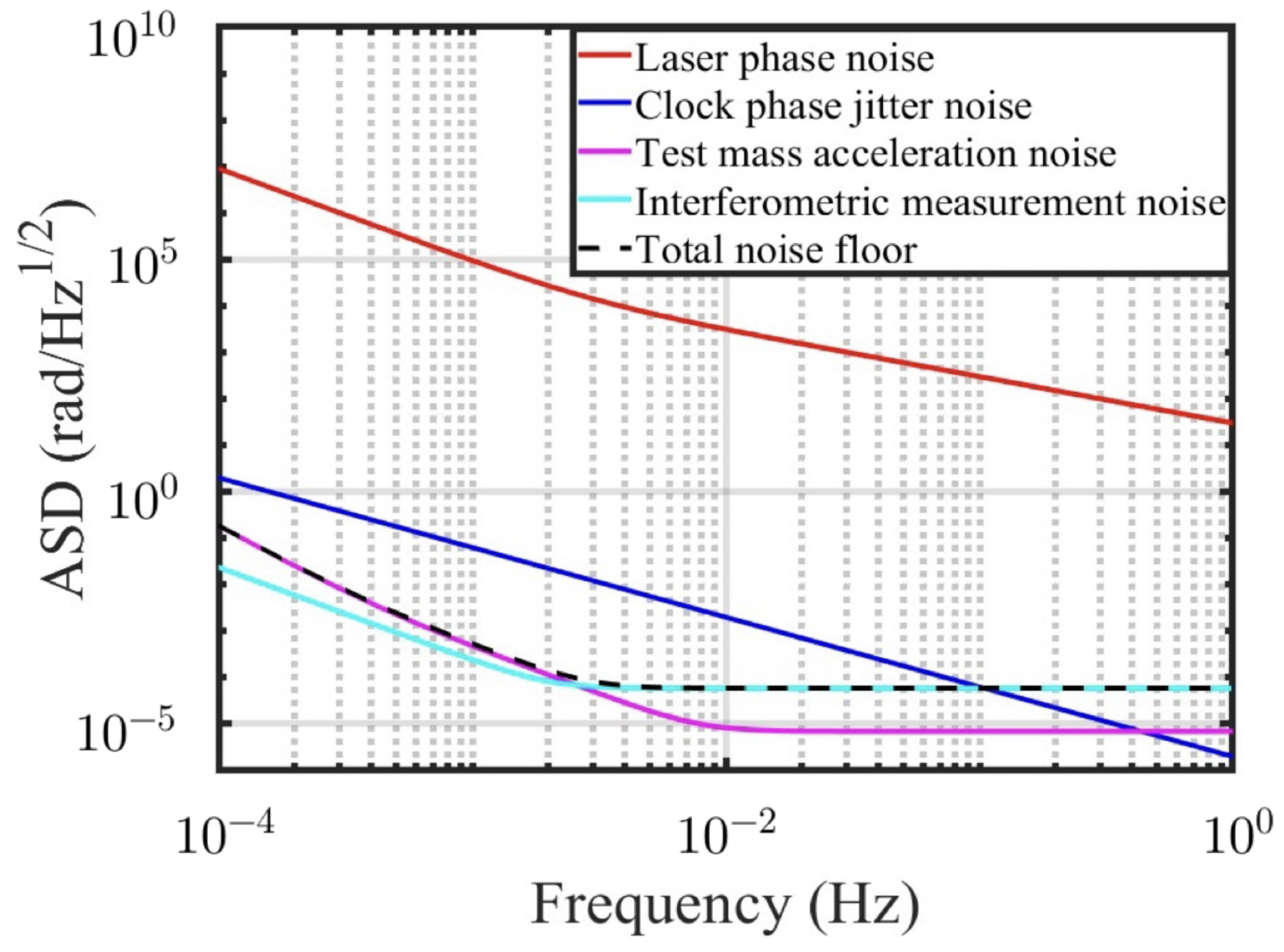
Taking the typical detector LISA as an example as shown in Table 1, below we show the amplitude spectra density (ASD) of different noises. Among them, laser phase noise is the most significant noise source within the GW detection frequency band, as indicated by the red line in the Figure 2. This noise mainly stems from the inherent instability of the pre-stabilized laser and the noise coupled with unequal arm lengths. It needs to be suppressed through the TDI data post-processing technique [48,49,50,51,52,53]. Then, the noise of the USO clock is typically significantly higher than the noise floor of the GW detector (the black dashed line represents the total noise floor, where the test mass acceleration noise dominates below 3 mHz and the interferometric measurement noise dominates at a high frequency bandwidth) in the frequency range of 0.1 mHz to 0.1 Hz, sometimes even exceeding it by two to three orders of magnitude, as shown by the blue line. It is mainly introduced because of the instability of the USO.

3. Clock Noise Impact Mechanism

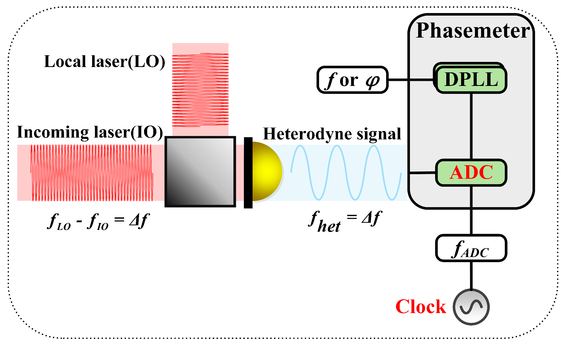
Space-borne GW detection uses heterodyne laser interferometry to measure the tiny displacement variations caused by passing GW. The detected interference data must be sampled by an ADC triggered by a clock to digitize the analog signal. The digitized interferometric data can then be processed to extract GW information, as shown in Figure 3.
The ideal sampling process is equidistant sampling. However, aperture jitter of the ADC and clock jitter during sampling can disrupt the sampling timing, resulting in a non-equidistant sampling process, as shown in Figure 4. The digitized signal is then represented at specific times according to the sampling period, which causes distortion in the sampled signal. This distortion affects space-borne GW detection, and the clock noise it introduces can be expressed as
δ ϕ = 2 π T ( δ t ADC + δ t clock ) .
T is the signal period, δ t ADC is the aperture jitter noise of the ADC, and δ t clock is the jitter noise of the triggered sampling clock.
To address the aperture jitter noise of the ADC, the pilot tone technique can be used for correction [55,56,57,58]. The basic principle is shown in Figure 5. After combining the pilot tone and the interference signal using an adder, the same ADC is used for sampling. Once the signal is digitized by the ADC, the interference and pilot tone signals are extracted using different digital filters and a digital phase-locked loop. According to Equation (7), ignoring sampling clock jitter noise, the aperture jitter phase noise in both the interference and pilot tone signals is given by
δ ϕ h = 2 π f h δ t ADC ,
δ ϕ p = 2 π f p δ t ADC ,
where f h is the interference signal frequency and f p is the pilot tone frequency. Since the interference signal and the pilot tone frequency signal pass through the same ADC, and the ADC aperture jitter phase noise is proportional to the input frequency, the ADC aperture jitter noise can be suppressed by a reasonable correction algorithm:
δ ϕ cor = δ ϕ h f h f p δ ϕ p .
After the ADC aperture jitter noise is suppressed, the stability of the on-board clock reference becomes the main clock noise source.
Currently, the specifications of typical space-borne USOs ( σ A 10 13 @1 s [19]) do not meet the requirements for GW detection from a hardware perspective. As shown in Figure 2, considering the size and power consumption of space-borne instruments, more stable optical clocks cannot be used in space-borne GW detection. Therefore, it is necessary to develop assistive techniques to suppress clock noise. Currently, researchers have proposed three strategies to suppress clock noise: the clock noise calibrated TDl technique, the optical comb TDl technique, and the sideband arm locking technique. The basic principles and current development status of these noise reduction techniques are introduced in detail.

4. Basic Principles of Clock Noise Suppression Techniques

4.1. TDI Technique

To suppress laser phase noise, researchers have proposed a data post-processing technique, the TDI technique [48,49,50,59]. This technique constructs a virtual equal-arm interferometer by recombining the measurement data stream with delays, achieving a physically unattainable equal-arm interferometer in space-borne GW detection. This process effectively suppresses common-mode laser phase noise.
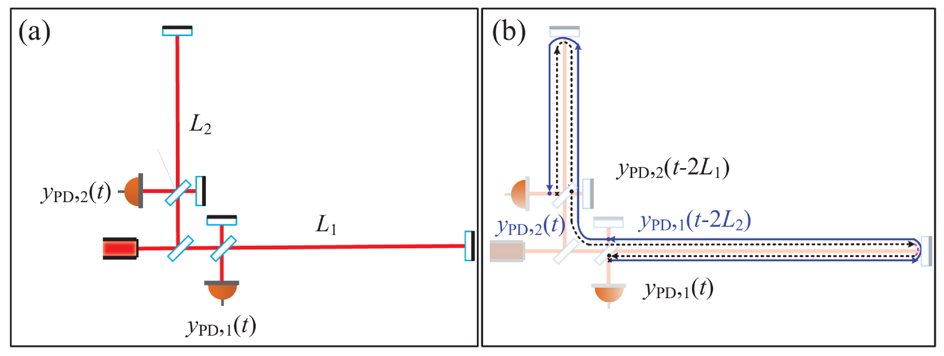
To make the principle of TDI technique for suppressing laser phase noise more intuitive, we ignore other noise sources present in practical space-based GW detection and consider only the laser phase noise and the GW signal. Intuitively, for an unequal arm, the Michelson interferometer is shown in Figure 6a, the laser light is beam-split by the beam splitter, and then interferes with the local laser light after a long round trip through the two unequal arms, respectively, and the interference data acquired by the two photodetectors (PDs) (considering the laser phase noise and signal) are
y P D 1 ( t ) = p t 2 L 1 c p ( t ) + h 1 ( t ) ,
y P D 2 ( t ) = p t 2 L 2 c p ( t ) + h 2 ( t ) .
Here, p ( t ) is the laser phase noise and h ( t ) is the GW signal. Due to the unequal lengths of the two arms, there will be a large residual laser phase noise after direct differencing of the two interferometric data, which will drown out the weak GW signal:
y P D 1 ( t ) y P D 2 ( t ) = p t 2 L 1 c p t 2 L 2 c + h 1 ( t ) h 2 ( t ) .
If the two interferometric data are delayed and then differenced, the residual laser phase noise is obtained as follows:
y P D 1 t 2 L 2 c y P D 2 t 2 L 1 c = p t 2 L 1 c p t 2 L 2 c + h 1 t 2 L 2 c h 2 t 2 L 1 c .
The laser phase noise is just canceled out by combining Equations (13) and (14), denoted as the x ( t ) combination below:
x ( t ) = y P D 1 t 2 L 2 c y P D 2 t 2 L 1 c y P D 1 ( t ) y P D 2 ( t ) = h 1 t 2 L 2 c h 2 t 2 L 1 c h 1 ( t ) h 2 ( t ) .
To better understand the TDI principle physically, rearrange the above equation as
x ( t ) = y P D 2 ( t ) + y P D 1 t 2 L 2 c y P D 1 ( t ) + y P D 2 t 2 L 1 c .
The constructed laser propagation path is shown in Figure 6b; the first curly bracket corresponds to the blue line light path in the figure, the second curly bracket corresponds to the black dashed line light path in the figure, and the laser propagates through the black dashed line and the blue line in equal paths, thus constructing an equal arm interference, which can be a common mode to eliminate the laser phase noise. If the light reflected by the two mirrors at the distal end of the interference arm in Figure 6a is considered light emitted from two distant satellites, and the lasers and detectors are considered to be located in the local satellites, the image can be correlated with the three satellites of the space-borne GW detector.

4.2. Clock Noise Calibrated TDI Technique

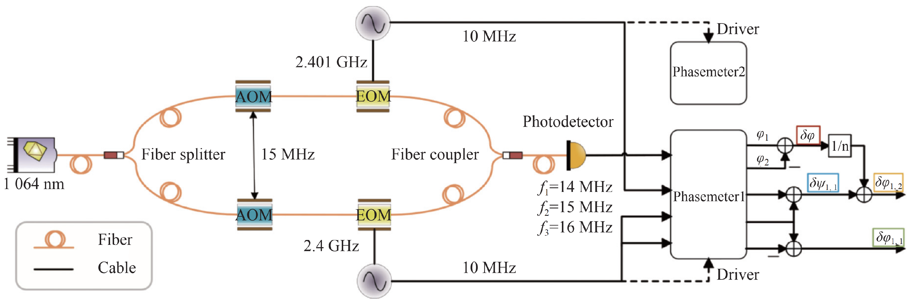
The key to the clock noise calibrated TDI technique is to construct an inter-satellite clock noise transfer link, as shown in Figure 7. The inter-satellite clock noise transfer link consists of two parts: the clock signal multiplication/division distribution system and the EOM sideband modulation unit. The multiplication/division distribution system primarily distributes the clock frequency to the ADC trigger frequency used for signal acquisition, the pilot tone frequency used to suppress ADC aperture jitter, and the modulation frequency that loads the frequency noise information from the multiplied clock. The system must ensure good coherence among these three frequencies to maintain uniformity in the clock reference within the satellite constellation. The EOM modulation unit modulates the clock signal onto the laser, and as the laser is transmitted between satellites, it interferes with the laser modulated at the remote end. (However, the modulation noise on the right-hand side is high [24], mainly originating from the fact that the pilot tone is obtained through the modulation frequency 2.4 GHz on the left-hand side after a 32-division frequency, while the homology between the 2.401 GHz on the right-hand side and the pilot tone becomes a little worse, thus introducing the modulation noise. There are two solutions at present, which can be obtained by electrically mixing the 2.4 GHz with the 2.401 GHz, and then captured by the phase meter to measure the modulation noise; or the information of modulation noise can also be obtained by sideband interference with a reference interferometer, so that the modulation noise can be deducted in post-processing. Considering that the frequency-division system is still under research and development, it is believed that the homology of different frequencies of the future frequency-division system will be improved and the modulation noise will meet the detection requirements.) This process generates both carrier interferometric data streams and sideband interferometric data streams. The two types of data streams can then be processed using the relevant algorithms to achieve clock noise suppression. The carrier interferometric data stream and sideband interferometric data stream can be represented as follows:
s i c = h i + D i 1 p ( i + 1 ) p i a i q i + N i + 2 π ν ( i + 1 ) n i 1 · D i 1 Δ ( i + 1 ) + n ( i 1 ) · Δ i , s i sb = h i + D i 1 p ( i + 1 ) p i + 2 π ν ( i + 1 ) n i 1 · D i 1 Δ ( i + 1 ) + n ( i 1 ) · Δ i + m ( i + 1 ) D i 1 q ( i + 1 ) m i q i c i q i + N i s b ,
where m i is the sideband modulation frequency coefficient and c i is the sideband heterodyne interference frequency coefficient:
m i = f m i f i ,
c i = ν i + 1 + m i + 1 f i + 1 ν i + m i f i f i .
Here, f m i denotes the sideband modulation frequency, which is typically set at 2.4 GHz. Combining carrier interferometric data and sideband interferometric data yields auxiliary measurements that mainly contain clock phase jitter noise:
r i s i c s i sb m ( i + 1 ) q i D i 1 q i + 1 , r i s i c s i sb m i 1 q i D ( i + 1 ) q i 1 .
Based on the auxiliary measurement quantities mentioned above, combined with the clock phase jitter noise calibrated TDI algorithm developed in the software, suppression of clock phase jitter noise can be achieved [24,25]. As an example, the Sagnac TDI combinations have a TDI-processed residual clock phase jitter noise of the form:
α 1 q = a 1 a 1 + b 1 1 + D 312 q 1 a 2 b 2 D 3 + D 2 1 b 2 a 2 q 2 D 31 a 3 b 3 + D 2 b 3 a 3 q 3 .
Using further the six auxiliary measurements shown in Equation (20), it is possible to construct a quantity that closely approximates the residual clock phase jitter noise term.
K α 1 = b 1 r 1 + D 3 r 2 + D 31 r 3 + b 2 + a 2 r 1 + b 2 a 2 r 1 + D 2 r 3 + b 3 a 3 r 1 + b 3 + a 3 r 1 + D 3 r 2 .
Further combining Equations (21) and (22) gives the following:
α 1 q K α 1 = 0 .
The above process demonstrates the basic principle of clock noise suppression using the clock noise calibrated TDI technique. Based on the above analysis, there are two key points in the clock noise calibrated TDI technique: one is to construct a low additional noise clock noise transmission link from the hardware to obtain the auxiliary clock noise measurements, and the other is to develop a clock noise calibrated TDI algorithm to process the data streams in order to suppress the clock noise containing delay.

4.3. Optical Comb TDI Technique

In the optical comb TDI technique, the key is to realize an optical-to-microwave frequency link using an optical comb. In general, there are two ways to realize an optical-microwave link. One is to stabilize a specific spectral line of the optical comb to an optical reference by feedback control of the optical comb repetition frequency f rep [61,62], while the optical comb carrier envelope frequency f ceo is locked to the microwave frequency reference so that f rep can be used as a seed source to generate the clock frequency by down-conversion using, for example, a direct digital synthesizer (DDS). Another is the transfer oscillator technique [63,64], which is based on rational mixing, filtering, and frequency division to immunize against the effects of optical comb noise, which, in turn, can be converted to microwave frequencies with ultra-high synchronization by means of an electrical network.
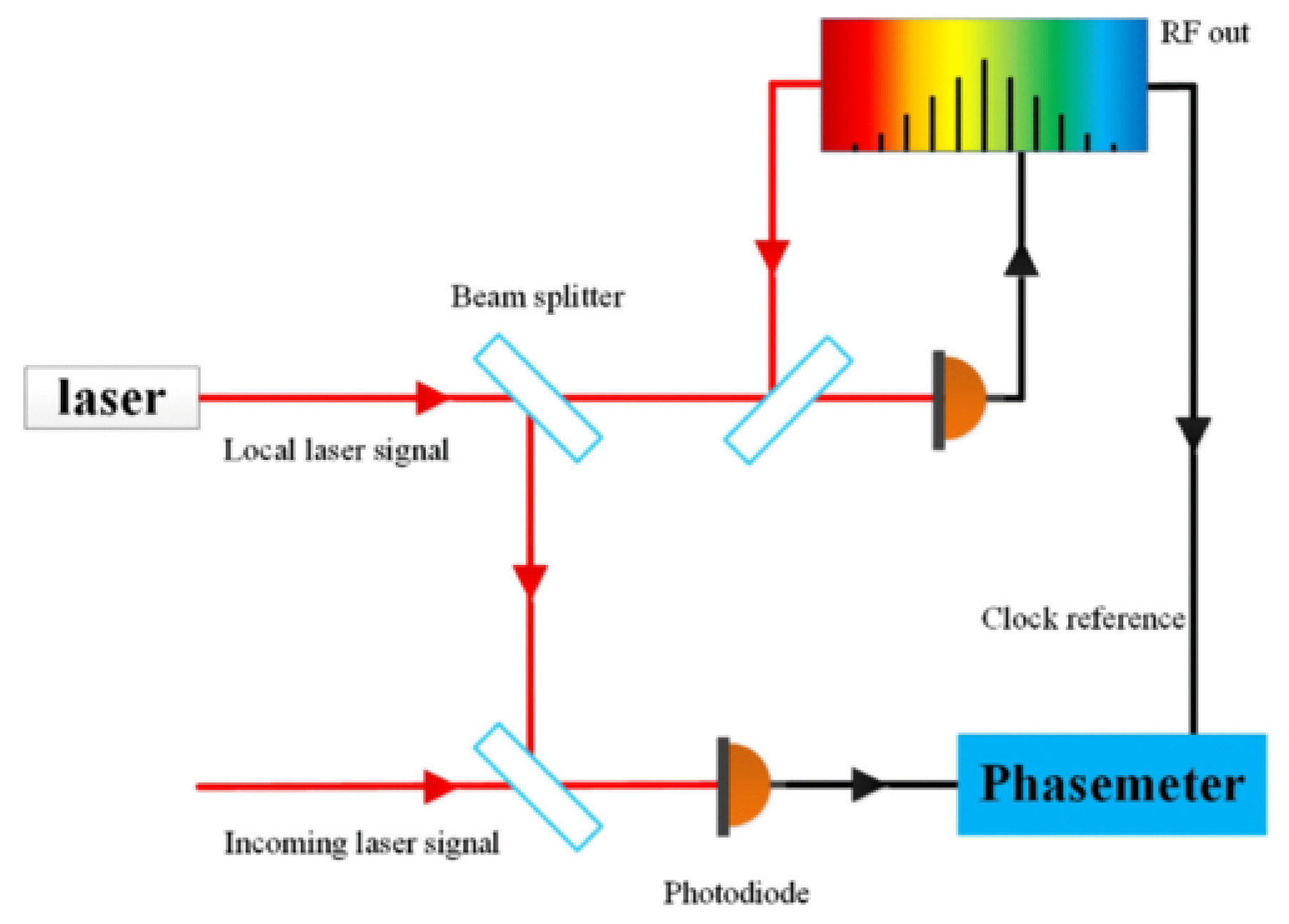
In the detection of GW in space, an optical comb can be used to generate a microwave signal homologous to the laser, which is used as a clock signal to trigger an ADC to sample the interferometric signal, as well as a PM to discriminate the frequency and phase. Figure 8 [27] shows the optical setup on the 1 platform in the spacecraft 1 (SC1), where the reference clock to trigger the ADC is generated by down-conversion of the cavity-stabilized laser by the optical comb. The other SC maintains the same configuration as the SC1. With the above optical comb technique, the clock phase jitter noise q i ( t ) and the laser phase noise p i ( t ) in SCi are related as follows:
q i ( t ) = f i ν i p i ( t ) + Δ q i ( t ) ,
where Δ q i ( t ) characterizes the level of homology between the laser phase and the clock frequency; the noise has been experimentally shown to be very small in the scientific band of GW detection in space [65], so the effect of this term is ignored in the analysis of this paper. Based on Equation (24), the six combined data streams shown in Equations (5) and (6) can be rewritten as follows
η i OFC = h i + D i 1 1 + b i + 1 f i + 1 ν i + 1 p i + 1 1 + a i f i ν i p i + 2 π ν ( i + 1 ) n i 1 · [ D i 1 δ ( i + 1 ) δ i ] + N i ,
η i OFC = h i + D ( i + 1 ) p i 1 1 + ( a i b i ) f i ν i p i + 2 π ν i 1 n i + 1 · [ δ i D ( i + 1 ) δ i 1 ] + N i .
From the above equation, it can be seen that in the case of optical comb connection, the clock phase jitter noise can be equivalently converted to laser phase noise, so it is only necessary to use the optical comb TDI algorithm to suppress this equivalent laser phase noise [26,27]. Compared with the clock noise calibrated TDI technique that suppresses the laser phase noise first and then the clock phase jitter noise, this technique is equivalent to suppressing the laser phase noise and the clock phase jitter noise at the same time in one step. Based on the above analysis, there are two key points included in the optical comb TDI technique: one is to obtain the interferometric data streams with laser and clock homology using the optical comb down conversion technique from the hardware, and the other is to develop the optical comb TDI algorithm, which processes the data streams in order to suppress the delay-containing laser phase noise and clock phase jitter noise.

4.4. Sideband Arm Locking Technique

Unlike the aforementioned two clock noise suppression techniques that rely on the integration of software and hardware, these methods not only require establishing a clock transmission link or using optical comb down-conversion technique to synchronize the laser and clock at the hardware level, but also necessitate the development of complex post-processing algorithms. Researchers proposed a novel scheme in 2024 [28]. This approach employs a sideband arm locking closed-loop feedback control mechanism to further reference clock stability to inter-satellite arm lengths, thereby achieving clock noise suppression at the hardware level.
Originally developed for suppressing laser phase noise, the arm locking technique was first introduced by a team from the Australian National University in 2003. They demonstrated that within the scientific bandwidth of GW detection, the stability of the arm length of the interferometer could serve as a reference to suppress laser phase noise [66], which gives rise to the laser arm locking technique. Subsequent studies on arm locking configuration design [67], Doppler effect estimation [68], controller design [69], and experimental verifications [70,71] have further validated its efficacy in reducing laser phase noise. Given that arm locking can suppress laser phase noise by over five orders of magnitude, while clock phase jitter noise only exceeds GW signals by about three orders of magnitude, researchers have preliminarily proposed a clock noise suppression scheme based on this technique. This section mainly introduces the fundamental principles of sideband arm locking.
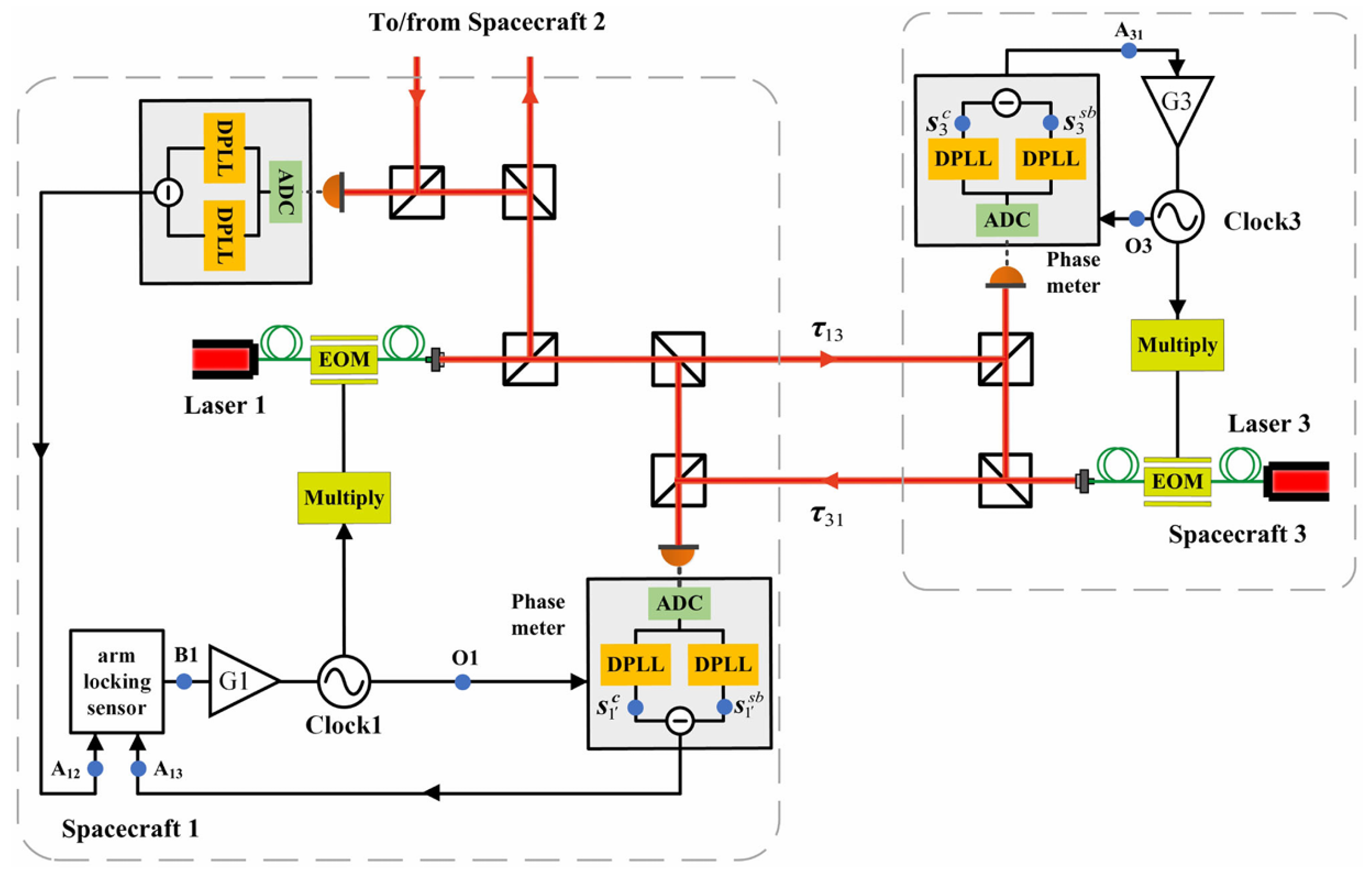
Figure 9 illustrates the sideband arm locking scheme for space-borne GW detection. Taking the typical GW detection mission LISA as an example, it consists of three SCs, each of which carries a USO as a clock reference. Only two of the SC are shown in Figure 9. SC1 is the master SC and clock1 is the master clock, which is converted from MHz to GHz by a frequency multiplier and injected into the EOM. Subsequently, the clock information is modulated into the phase of the laser by the electro-optical effect of the EOM to generate the upper and lower sidebands. The modulated laser is passed to the far-end SC and interferes with the far-end laser to form a carrier data stream and a sideband data stream. The information in the carrier and sideband data streams can be extracted by two digital phase-locked loops, respectively. Considering only the laser phase noise and clock phase jitter noise, the frequency domain expression of the carrier data stream can be expressed as follows:
s 3 c ( ω ) = p 1 ( ω ) e s τ 13 p 3 ( ω ) a 3 q 3 ,
where p is the laser phase noise, s is the Laplace operator, τ 13 is the light propagation time between SC1 and SC3, a is the interference coefficient, and q is the clock phase jitter noise. Similarly, in the frequency domain, the sideband data stream s 3 s b can be expressed as follows:
s 3 s b ( ω ) = p 1 ( ω ) e s τ 13 p 3 ( ω ) + m 1 q 1 e s τ 13 m 3 q 3 ( m 1 m 3 a 3 ) q 3 .
Combining Equations (27) and (28), the comparison information A 31 of clock 1 and clock 3 in SC3 can be obtained:
A 31 ( ω ) = s 3 c ( ω ) s 3 s b ( ω ) = m 1 q 3 ( ω ) m 1 q 1 ( ω ) e s τ 13 ,
where m is the frequency multiplication factor. This data stream mainly contains clock phase jitter noise, so it can be used as an error data stream to make clock 3 track clock 1. After the closed-loop control, the noise of clock 3 (blue circle labeled O3) is as follows:
O 3 ( ω ) 1 1 + m 1 G 3 ( ω ) q 3 ( ω ) + m 1 G 3 ( ω ) 1 + m 1 G 3 ( ω ) q 1 ( ω ) e s τ 13 q 1 ( ω ) e s τ 13 ,
where G 3 ( ω ) is the control gain. Here, different clock center frequencies are considered approximately equal. At this point, clock 3 can track clock 1 well. Afterwards, clock 3 is passed to SC1 after inter-satellite delay, and then it is compared with clock 1 to obtain the error data stream:
A 13 ( ω ) = m 3 q 1 ( ω ) m 3 O 3 ( ω ) e s τ 31 m 3 q 1 ( ω ) ( 1 e s ( τ 31 + τ 13 ) ) .
Using A 13 as the error data stream, the closed-loop clock phase jitter noise at the output of clock 1 (blue circle labeled O1) is represented as follows:
O 1 ( ω ) = q 1 ( ω ) G 1 ( ω ) A 13 ( ω ) ,
After closing the loop, q 1 ( ω ) in the error data stream A 13 becomes O 1 ( ω ) . It can be obtained by substituting Equation (31) in Equation (32):
O 1 ( ω ) 1 1 + G 1 ( ω ) m 3 ( 1 e s ( τ 31 + τ 13 ) ) q 1 ( ω ) .
Equation (33) demonstrates that the closed-loop clock phase jitter noise O 1 ( ω ) (i.e., the residual noise of clock 1 when the sideband arm locking loops are closed) is suppressed by a factor of G 1 ( ω ) m 3 relative to its open-loop counterpart q 1 ( ω ) .

5. Current Research Status of Clock Noise Suppression Techniques

5.1. Clock Noise Calibrated TDI Technique

Whether the clock noise calibrated TDI technique can effectively suppress clock noise requires a corresponding experimental verification, which contains two aspects. On the one hand, it is necessary to verify whether the TDI technique can suppress the clock noise below the detector noise floor level, and on the other hand, it is necessary to verify whether the additional noise introduced in the process of the adoption of the technique is lower than the detector noise floor level. Based on the above two points, this subsection introduces the current research status of the EOM and frequency distribution system, which are the key devices in the clock noise calibrated TDI technique, and the related experimental verification of whether the clock noise can be successfully suppressed after the clock noise transmission link is constructed.
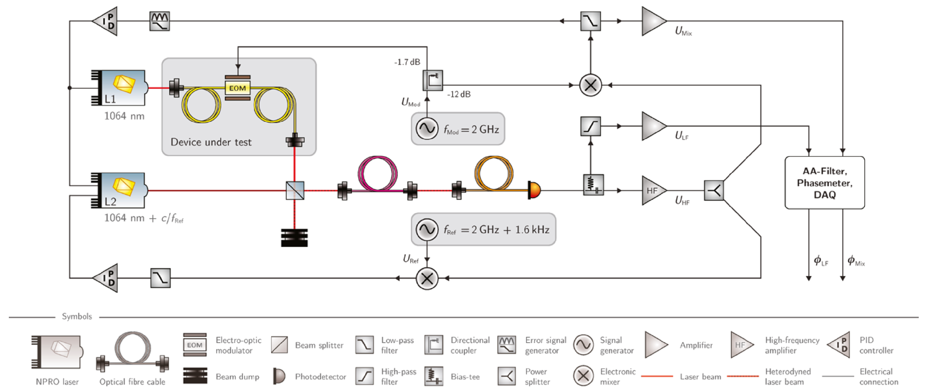
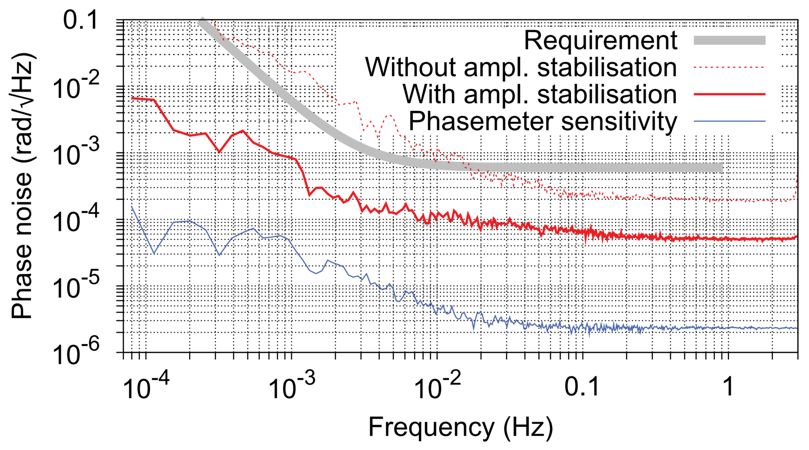
In terms of EOM device testing, JPL Labs [35], the Albert Einstein Institute (AEI) in Germany [36], Sun Yat-sen University [37], conducted the corresponding tests. The results of the experiments showed that the additional noise of the EOM device can meet the needs of a typical GW detected mission; this paper takes the experiments built by the AEI team in 2010 as an example to introduce. As shown in Figure 10, the EOM test optical path built by the AEI team, the main laser passes through the EOM (model: Jenoptik), generating upper and lower sidebands. These sidebands then interfere with the measurement laser. The measurement laser tracks the main laser through heterodyne phase locking, thus avoiding the introduction of additional laser phase noise. The frequency of the heterodyne locking (2 GHz + 1.6 kHz) and the modulation frequency of the EOM (2 GHz) are close, at which point the measurement laser interferes with the lower sideband of the main laser and the down-converted 1.6 kHz signal is captured by the PD, which is, in turn, captured by the PM. In addition, the PM also captured the mixed frequency signals of the phase locked frequency and the EOM modulation frequency, which was used as a reference to compare the additional noise introduced after the EOM modulation, and the experimental results are shown in Figure 11. The gray line is the additional noise requirement at a 2 GHz modulation frequency, and the red dotted line depicts the additional noise of the laser amplitude prior to stabilization. Once the active laser amplitude stabilization process is completed, the additional noise of EOM is lower than the requirement curve in the full frequency band; the experimental results show that the additional noise of EOM can meet the requirements of a typical GW detection mission.
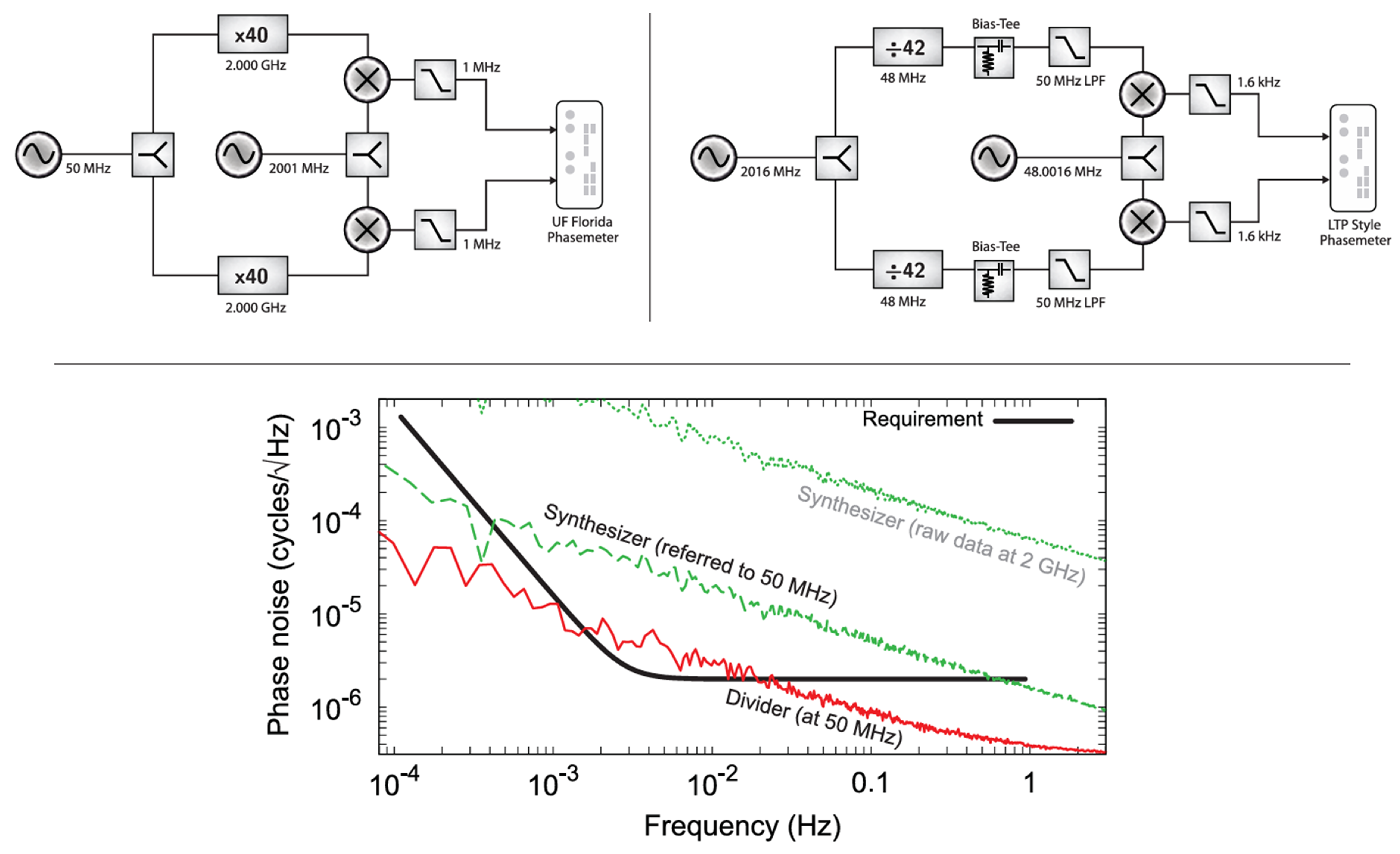
In the frequency distribution system testing, it is divided into a frequency doubling system (doubling the USO signal to a modulation frequency of GHz) and a frequency dividing system (dividing the modulation frequency of GHz to a pilot tone frequency of MHz). The AEI team carried out both the frequency divider (model: UXN14M9PE) and the frequency doubler tests (customized by Ingenieurburo Gronefeld) in 2011 [72], as shown in Figure 12. The experimental design employs a differential link approach. By comparing the results of two similar links, it can achieve common-mode rejection of the noise from the signal source. The results of the differential measurements are shown in Figure 12, indicating that the phase noise of the frequency divider can basically meet the requirements of the LISA mission in the full frequency band, but the phase noise of the frequency multiplier is much higher than the requirements of the mission. This may be due to the correlation between the input amplitude and the output phase.
In terms of clock noise transmission links, the AEI team [32], the Chinese Academy of Sciences team, the Sun Yat-sen University team [37], and the HUST team [73] conducted the corresponding tests and research.
As shown in Figure 13, the AEI team verified the synchronous techniques of the clock between three satellites using a hexagonal OP in 2022 [32]. The experiment consisted of three lasers, three time–frequency distribution links, and three clock noise transfer links. The experiment used a hexagonal optical platform to create interference between pairs of lasers, thus constructing a combination of zero-noise test data a b + b c + c a . Since the experiment employed different clock triggers for phase data acquisition, clock noise was introduced into the zero-noise combination. The experiment adopted EOM to construct the clock transmission link and combined the principle of the clock noise calibrated TDI algorithm to achieve the suppression of clock noise. The experiment used an integrated OP and vacuum and other measures to suppress the noise of the interferometer, and the noise floor level could reach 1 μcycle / Hz 1 / 2 @ 0.1 Hz. Ultimately, the experiment demonstrated synchronous clock techniques between the three satellites and clock jitter noise suppression techniques, and the experimental results reached the system noise floor level. The team stated that in the future they would analyze key components such as the frequency distribution system to enhance their thermal stability and reduce their coupling effects with the measurement process. They also planned to upgrade the experimental setup, including simulating more functions and components of LISA. The hexagonal OP, as the main test bed for the LISA measurement chain, will continue to serve as the backbone of technological development for ground-based validation of the feasibility of GW detection missions in space.
The overall layout of the Taiji mission has many similarities with LISA, but there are certain differences in the optical path system, arm length configuration, and operational orbit, which necessitates the parameter design of the clock noise transfer link (frequency multiplication coefficient and heterodyne frequency) to be ground-validated. For this reason, the Chinese Academy of Sciences team carried out the ground verification experiment of the inter-satellite clock noise transfer of the Taiji mission in 2023 [74]. As shown in Figure 14, the experiment employed a single laser source, utilizing two acousto-optic modulators (AOMs) to achieve heterodyne interference. Subsequently, the light passes through two EOMs to simulate the transmission of inter-satellite clock noise. Ultimately, the experiment verifies the principle of the sideband frequency multiplication transmission scheme, and in the 0.05 Hz∼1 Hz band, the inter-satellite clock noise suppression effect is better than 2 π × 10 5 rad / Hz 1 / 2 , which meets the noise requirements of Taiji Pathfinder; it has laid a certain theoretical and experimental foundation for the clock noise transfer scheme and parameter design of the future Taiji mission.
To simulate clock noise transmission under weak-light conditions, Sun Yat-sen University built the experimental setup shown in Figure 15 in 2023 [37]. The setup includes a laser, a 10 km long optical fiber to introduce delay, two attenuators to introduce weak light, two circulators to form an interference optical path, and two sets of EOM modulation systems to simulate bi-directional clock noise transmission. The optical power transmitted by the system is less than 1 nW, the time delay is about 50 µs, and the Doppler frequency shift between SC is simulated by frequency modulation of the laser. The experimental results showed that above the 6 mHz frequency range, the residual clock jitter noise introduced by the optical transmission link is less than 40 fs / Hz 1 / 2 , and the fractional frequency instability at 1000 s is less than 6.7 × 10 17 , meeting the requirements of the Tianqin mission.
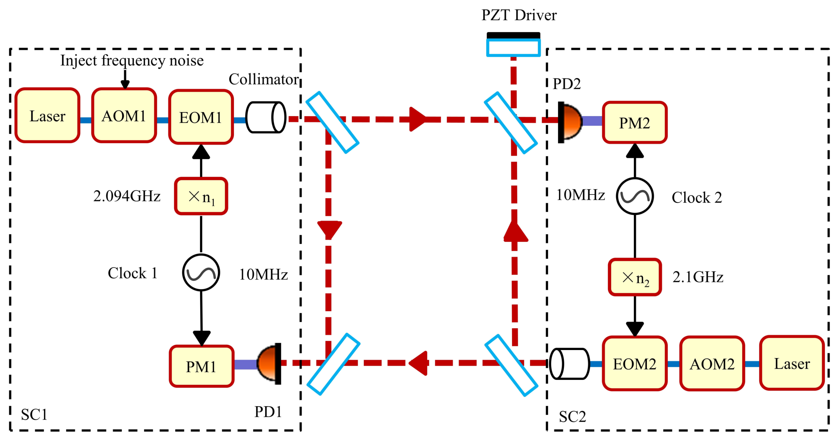
Considering the construction of a clock noise transmission link, the HUST team simulated clock noise transmission in a two-satellite, two-link configuration in 2023 [73]. They investigated whether the corresponding TDI data processing techniques could successfully recover weak displacement signals that were submerged by clock noise. The simulation validated inter-satellite clock synchronization, clock jitter noise suppression, and the extraction of faint signals. As shown in Figure 16, the laser in the experiment is split into two paths through the optical fiber, passing through different AOMs to introduce the heterodyne frequency modulation, followed by the EOM to introduce the sideband modulation, and then through a square loop to simulate the laser interference between the two satellites. The interference data are collected by PMs, and different PMs are triggered by different clocks, thus introducing clock noise. In addition, piezoelectric transducer (PZT)-driven mirrors are placed to introduce a real weak displacement signal. Since two free crystals are used as clocks, the clock noise will drown out the PZT weak displacement signal, and in order to extract this weak signal, a clock noise transfer link (i.e., the clock signal is multiplied to GHz by a signal source and then modulated to the laser via EOM) needs to be constructed to suppress the clock noise. The experiment used the idea of TDI constructing an equal arm and the idea of clock noise transfer comparison, and finally demonstrated that the laser phase noise was suppressed by about 5 orders of magnitude and the clock noise was suppressed by about 2 orders of magnitude, and the injected weak displacement signal with an amplitude of about 60 pm was successfully recovered. The experimental results are limited by the noise floor level of the laser interferometer, 10 μcycle / Hz 1 / 2 @ 1 Hz. This work realized the proof-of-principle of the clock noise suppression by the clock noise calibrated technique and provides important technical support for the extraction of GW signals at the picometer scale in future space-borne GW detection.
In general, the clock noise calibrated technique has developed relatively maturely. In terms of key component testing, multiple studies have shown that the additional noise of typical EOMs meets the requirements, while the additional noise of the frequency conversion distribution system is slightly higher than the requirements for space-borne GW detection tasks, which will be a key area for future research. In terms of noise suppression, although several principle experiments have demonstrated that the clock noise calibrated technique effectively suppresses clock noise, bringing the experiment to the noise floor of the system, current principle experiments have not addressed long time-delay noise. Additionally, these experiments have not replicated the three-satellite, six-link architecture or the three-stage measurement method of space-borne GW detectors, so they cannot truly validate the applicability of the clock noise calibrated TDI technique under space conditions. Therefore, future ground-based experimental verification designs must further consider these factors to achieve effective validation of the clock noise calibrated TDI technique.

5.2. Optical Comb TDI Technique

The optical comb TDI technique is a novel technique; the related experimental research is currently in the principle verification stage, where we will introduce several typical optical comb TDI verification experiments.
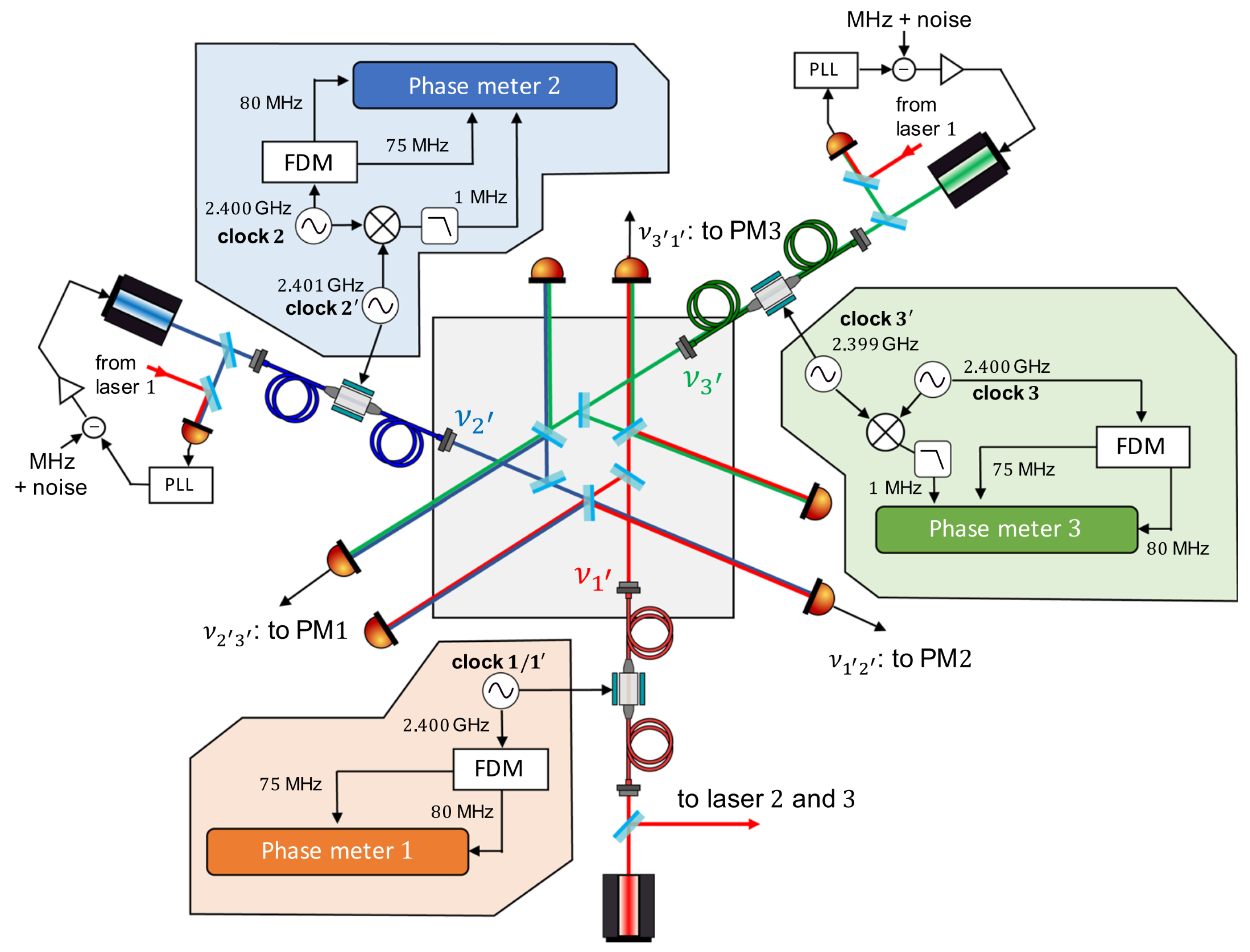
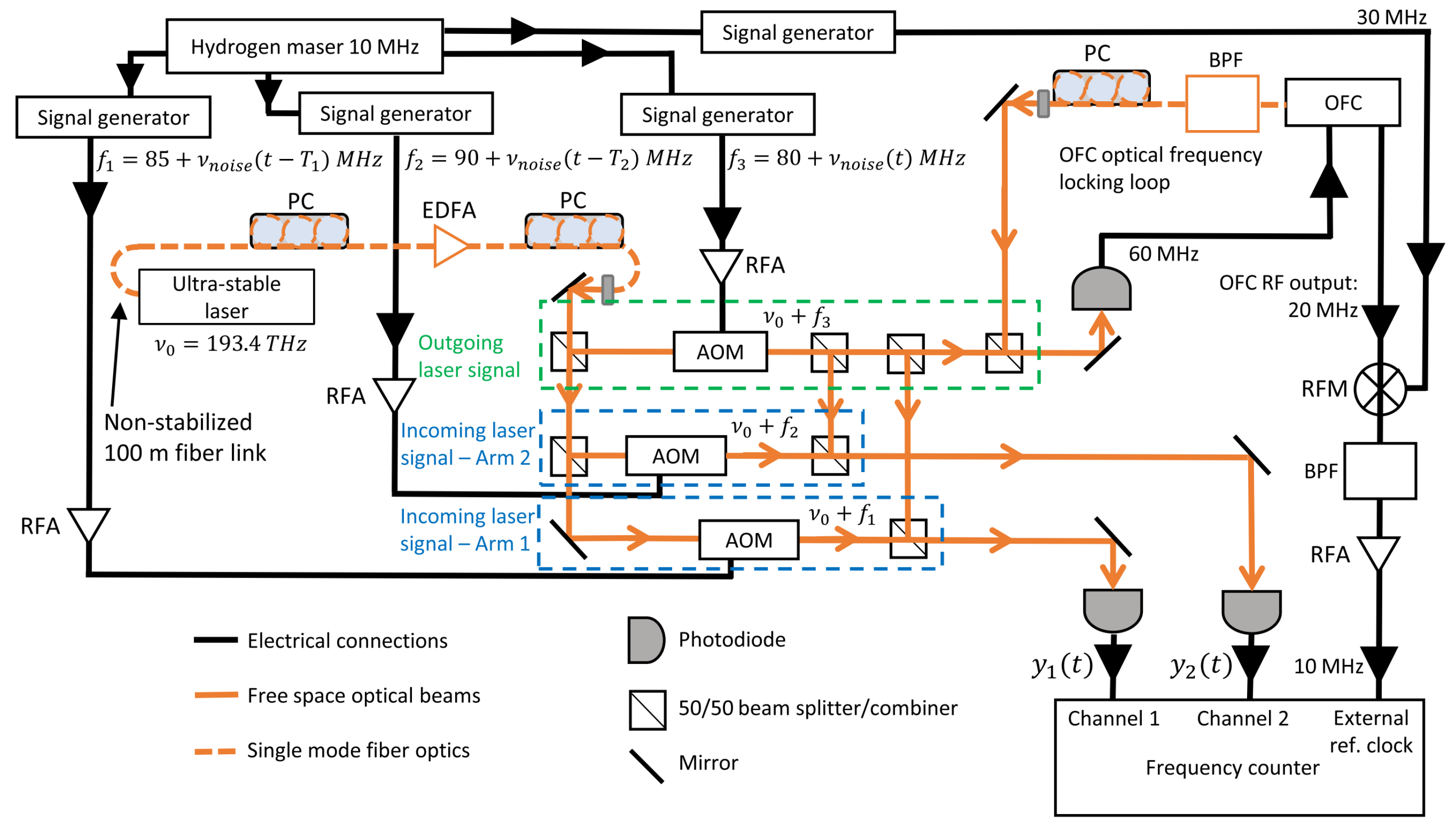
The JPL team used an AOM and optical comb to validate the optical comb TDI technique in 2020 [33]. As shown in Figure 17, the experiment consists of an ultra-stable laser and an optical comb, and a Mach Zende-type interferometer is used for the entire optical path. In the experiment, a noise sequence containing a delay is generated by the computer, followed by generating an analog electrical signal from the noise sequence and driving the AOM to achieve the delayed injection of the laser phase noise, thus simulating a Michelson interferometer with unequal arm lengths. For the clock signal, the optical comb is referenced to an ultra-stable laser, and then the repetition frequency of the locked optical comb is used as the clock source, thus homogenizing the laser phase noise and clock noise. The experiment was constructed using a standard optical breadboard, with the entire system enclosed in thermal insulation to suppress noise in the laser interferometer, and the experimental noise floor reached the level of 160 μcycle / Hz 1 / 2 @ 0.01 Hz. Ultimately, this experiment demonstrated the ability of the optical comb TDI technique to simultaneously suppress laser phase noise and clock noise to the system noise floor level. The final 10 MHz clock signal generated in this experiment is obtained by mixing the 20 MHz microwave signal generated by the optical comb and the 30 MHz microwave signal generated by the hydrogen clock; at this time, there is a clock jitter contributed by the hydrogen clock in the clock signal, and there is a possibility of loss of locking in the homologation of the laser and the clock by using locking, which leads to the failure of the down-conversion, so this homologation method still needs to be improved.
In order to avoid downconversion failures due to the locking mode being unlocked, the HUST team further combined the transfer oscillator technique with the optical comb TDI technique [34] in 2023 to perform the experimental verification of the optical comb TDI. The advantages of the transfer oscillator are that there is no need to lock the optical comb in the signal laser, and the electrical configuration can be designed to be immune to optical comb noise [63,64]. As shown in Figure 18, the experiment uses an iodine-stabilized laser as the main light source, which is then split into two: one path is used for beat frequency with the optical comb, and this interferometric data stream is filtered and amplified, and then mixed with the carrier envelope frequency of the optical comb, a step that can be immune to the effect of the carrier envelope frequency. Due to the low signal-to-noise ratio of the beat frequency, a lock-in amplifier is used to stabilize the amplitude of the signal, avoiding the introduction of amplitude jitter to frequency jitter noise in subsequent DDS. Then, through the reasonable setting of the DDS frequency division parameter and the mixer’s up-conversion down-conversion selection, it is immune to the influence of repetition frequency. Finally, the frequency division of the iodine-stabilized laser is achieved and generates a 10 MHz signal as the trigger clock of the PM. Another path of the laser interferes with a cavity-stabilized laser, which has higher stability. In this case, the beat frequency signal is dominated by the iodine-stabilized laser. Subsequently, different electrical delays are introduced through an electronic delay unit to simulate a TDI experiment. The experimental results show a good noise suppression effect, reaching the system noise floor level, limited by the electronics noise.
Overall, the optical frequency comb-based TDI technique is still in the development stage. Further in-depth exploration and research are needed for its key technology, which is the noise assessment of the optical comb downconversion. Furthermore, the size, power consumption, and long-term stability of space-borne optical combs also require further scientific research and technological innovation.

5.3. Sideband Arm Locking Technique

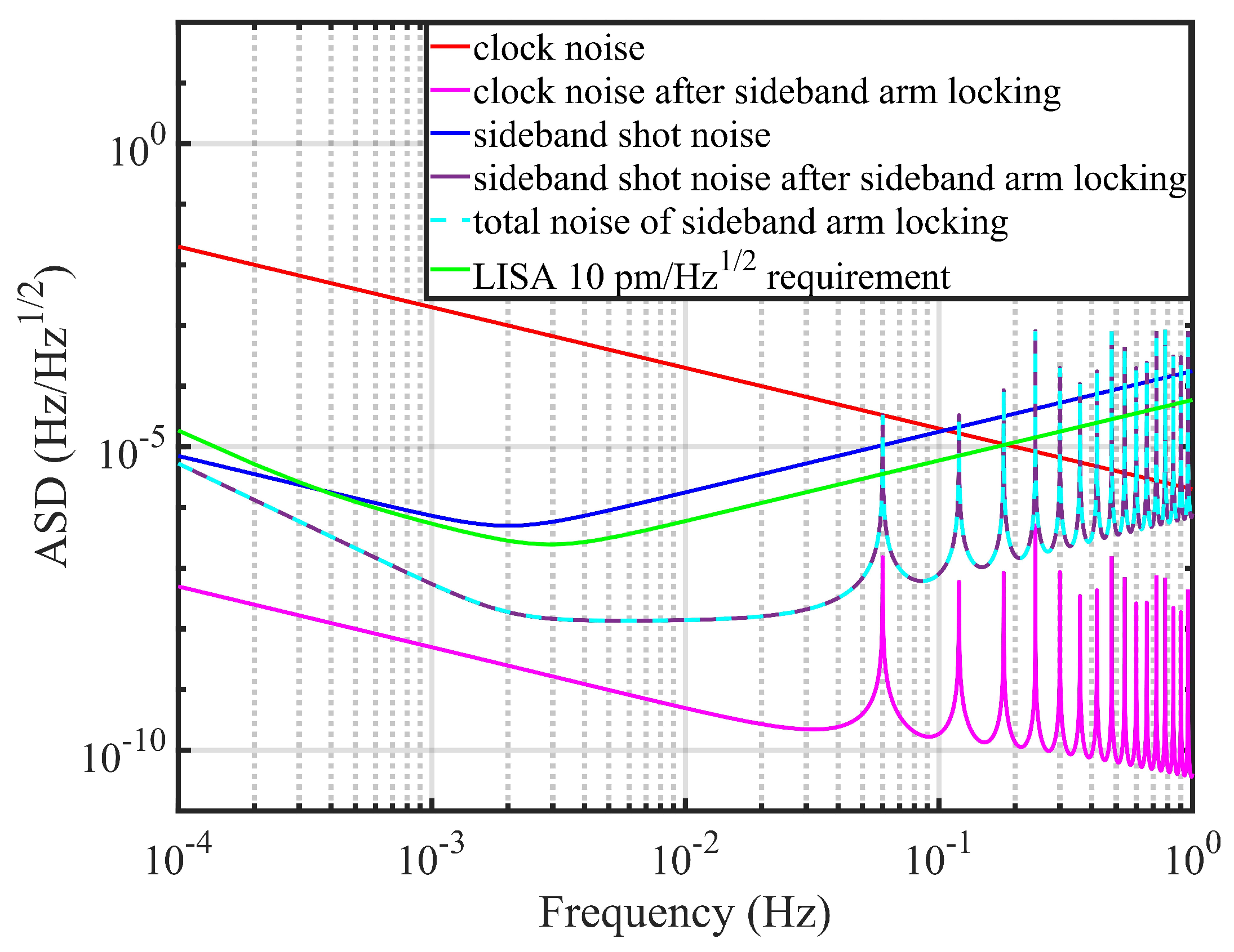
The sideband arm locking technique is a relatively new technique that has not yet been experimentally verified. Currently, only simulation verification has been conducted. The result of the sideband arm locking in the frequency domain is shown in Figure 19, where the red line shows the jitter noise of the raw clock frequency in Hz / Hz 1 / 2 units, which is higher than the LISA requirement as shown by the green line, and thus the clock noise swamps the GW signal. After the sideband arm locks, as shown by the pink line, the clock noise is suppressed by about 3–5 orders of magnitude below the requirement. The dominant noise of the sideband arm locking is the sideband shot noise as shown by the blue line, and the sideband noise becomes the purple line after the loop is closed. The total noise in the sideband arm locking is the blue dashed line and is below the LISA requirement at less than 0.06 Hz. The results show that the clock noise within the science bandwidth can be effectively suppressed by implementing closed-loop control to meet the LISA requirements.
The key technical points and experimental performance levels of these clock noise suppression techniques are summarized and compared, as presented in Table 2.

6. Conclusions and Prospects

For current space-based GW detection missions, optical clocks have achieved extremely high stability ( 10 18 ), but their large size and complexity make them unsuitable. Instead, smaller, low-power quartz clocks are preferred, but their lower stability ( 10 13 ), which falls short of the 10 15 requirement, thus introduces significant clock jitter noise that affects detector performance.
Clock noise primarily arises from the aperture jitter of the ADC and the jitter of sampling clocks. Although pilot tone techniques effectively mitigate ADC aperture jitter, the remaining sampling clock jitter noise remains critical. This review has examined three prominent techniques for clock noise suppression techniques: clock noise calibrated TDI technique, optical comb TDI technique, and sideband locking arm technique.
The clock noise calibrated TDI technique leverages EOMs to transfer clock noise onto laser sidebands, creating inter-satellite clock noise comparison links. This provides additional clock noise measurements, and post-processing algorithms then suppress the noise. Experimental studies have shown that the additional noise from EOMs can meet the requirements of typical GW detection missions across the entire frequency band, and the frequency division system essentially satisfies the detection needs. The clock noise calibrated TDI technique is the most mature, with robust experimental support. Future work should focus on optimizing frequency distribution systems and expanding ground-based tests to emulate space conditions more accurately.
The optical comb TDI technique uses optical frequency combs to down-convert laser frequencies, synchronizing clock and laser. By converting clock noise into an equivalent laser phase noise, it allows existing TDI algorithms to suppress both simultaneously. Preliminary experiments, including phase-locking and transfer oscillator methods, have shown promise, achieving noise suppression down to system limits. The optical comb TDI technique is a promising but nascent technology. Its key advantage is that, as the stability of the laser improves, the stability of the clock obtained through optical comb down-conversion also increases, potentially generating a clock that directly meets the requirements of GW detection missions.
A hardware-level solution, the sideband arm locking technique employs the locking arm technique and suppresses clock noise through a closed-loop feedback control technique, thereby directly generating a clock that meets the requirements of GW detection. Simulations indicate noise suppression of 3 to 5 orders of magnitude, though experimental validation is still pending. This technique offers a novel hardware-driven alternative but requires further development to assess its compatibility with GW detection systems and to demonstrate practical feasibility.
The clock noise calibrated and the optical comb TDI techniques complement each other, providing redundancy for mission robustness. Meanwhile, the sideband arm locking technique could serve as a standalone or backup solution.
In summary, this review provides a comprehensive analysis of clock noise suppression techniques, highlighting their principles, current status, and future prospects. By addressing the limitations of optical clocks and advancing auxiliary methods, these innovations are paving the way for space-borne GW detection, enabling unprecedented explorations of astrophysics, gravitation, and cosmology.

Author Contributions

Conceptualization, Y.T.; formal analysis, Y.X., A.F. and Y.T.; investigation, Y.X., M.X. and Y.T.; writing—original draft preparation, Y.X., M.X. and Y.T.; writing—review and editing, Y.X., M.X., Y.T. and C.S.; funding acquisition, Y.T. and C.S. All authors have read and agreed to the published version of the manuscript.

Funding

This work was supported by the National Key Research and Development Program of China (Grants No. 2023YFC2206100 and No. 2022YFC2204602), National Natural Science Foundation of China (Grant No. 12175076), and Knowledge Innovation Program of Wuhan-Basi Research (2023010201010048).

Data Availability Statement

No data were used for the research described in the article.

Conflicts of Interest

The authors declare no conflicts of interest.

References

  1. Einstein, A. Die grundlage der allgemeinen relativitätstheorie. Annalen der Physik 1916, 354, 769–822. [Google Scholar] [CrossRef]
  2. Abbott, B.P.; Abbott, R.; Abbott, T.D.; Abernathy, M.R.; Acernese, F.; Ackley, K.; Adams, C.; Adams, T.; Addesso, P.; LIGO Scientific Collaboration and Virgo Collaboration. Observation of gravitational waves from a binary black hole merger. Phys. Rev. Lett. 2016, 116, 061102. [Google Scholar] [CrossRef]
  3. Abbott, B.P.; Abbott, R.; Abbott, T.D.; Abernathy, M.R.; Acernese, F.; Ackley, K.; Adams, C.; Adams, T.; Addesso, P.; LIGO Scientific Collaboration and Virgo Collaboration. GW151226: Observation of gravitational waves from a 22-solar-mass binary black hole coalescence. Phys. Rev. Lett. 2016, 116, 241103. [Google Scholar] [CrossRef] [PubMed]
  4. Cai, R.G. Revealing the amplitude of primordial curvature perturbations on small scales from Primordial black hole binaries for gravitational wave detection. Sci. China Phys. Mech. Astron. 2023, 66, 260461. [Google Scholar] [CrossRef]
  5. He, S.; Li, L.; Li, Z.; Wang, S.J. Gravitational waves and primordial black hole productions from gluodynamics by holography. Sci. China Phys. Mech. Astron. 2024, 67, 240411. [Google Scholar] [CrossRef]
  6. Wang, C.W.Z.; Zhu, J.B.; Huang, G.Q.; Shu, F.W. Testing the first law of black hole mechanics with gravitational waves. arXiv 2024, arXiv:2304.10117. [Google Scholar] [CrossRef]
  7. Cervantes-Cota, J.L.; Galindo-Uribarri, S.; Smoot, G.F. A brief history of gravitational waves. Universe 2016, 2, 22. [Google Scholar] [CrossRef]
  8. Chen, C.M.; Nester, J.M.; Ni, W.T. A brief history of gravitational wave research. Chin. J. Phys. 2017, 55, 142–169. [Google Scholar] [CrossRef]
  9. Li, J.; Liu, F.; Pan, Y.; Wang, Z.; Cao, M.; Wang, M.; Zhang, F.; Zhang, J.; Zhu, Z.H. Detecting gravitational wave with an interferometric seismometer array on lunar nearside. Sci. China Phys. Mech. Astron. 2023, 66, 109513. [Google Scholar] [CrossRef]
  10. Shao, L. Perceiving deci-Hertz gravitational waves over the Moon. Sci. China Phys. Mech. Astron. 2023, 66, 119531. [Google Scholar] [CrossRef]
  11. Torres-Orjuela, A.; Huang, S.J.; Liang, Z.C.; Liu, S.; Wang, H.T.; Ye, C.Q.; Hu, Y.M.; Mei, J. Detection of astrophysical gravitational wave sources by TianQin and LISA. Sci. China Phys. Mech. Astron. 2024, 67, 259511. [Google Scholar] [CrossRef]
  12. Han, Z. FAST unveils a new era in the discovery of long-period pulsars in globular clusters. Sci. China Phys. Mech. Astron. 2024, 67, 269532. [Google Scholar] [CrossRef]
  13. Amaro-Seoane, P.; Audley, H.; Babak, S.; Baker, J.; Barausse, E.; Bender, P.; Berti, E.; Binetruy, P.; Born, M.; Bortoluzzi, D.; et al. Laser Interferometer Space Antenna. arXiv 2017, arXiv:1702.00786. [Google Scholar] [CrossRef]
  14. Luo, J.; Chen, L.S.; Duan, H.Z.; Gong, Y.G.; Hu, S.; Ji, J.; Liu, Q.; Mei, J.; Milyukov, V.; Sazhin, M.; et al. TianQin: A space-borne gravitational wave detector. Class. Quantum Gravity 2016, 33, 035010. [Google Scholar] [CrossRef]
  15. Hu, W.R.; Wu, Y.L. The Taiji program in space for gravitational wave physics and the nature of gravity. Natl. Sci. Rev. 2017, 4, 685–686. [Google Scholar] [CrossRef]
  16. Derevianko, A.; Gibble, K.; Hollberg, L.; Newbury, N.R.; Oates, C.; Safronova, M.S.; Sinclair, L.C.; Yu, N. Fundamental physics with a state-of-the-art optical clock in space. Quantum Sci. Technol. 2022, 7, 044002. [Google Scholar] [CrossRef]
  17. Kolkowitz, S.; Pikovski, I.; Langellier, N.; Lukin, M.; Walsworth, R.; Ye, J. Gravitational wave detection with optical lattice atomic clocks. Phys. Rev. D 2016, 94, 124043. [Google Scholar] [CrossRef]
  18. Wang, B.; Li, B.; Xiao, Q.; Mo, G.; Cai, Y.F. Space-based optical lattice clocks as gravitational wave detectors in search for new physics. Sci. China Phys. Mech. Astron. 2025, 68, 249512. [Google Scholar] [CrossRef]
  19. Weaver, G.; Garstecki, J.; Reynolds, S. The performance of ultra-stable oscillators for the Gravity Recovery and Interior Laboratory (GRAIL). In Proceedings of the Annual Precise Time & Time Interval Systems & Applications Meeting, Reston, VA, USA, 15–18 November 2010. [Google Scholar]
  20. Hellings, R.W. Elimination of clock jitter noise in spaceborne laser interferometers. Phys. Rev. D 2001, 64, 022002. [Google Scholar] [CrossRef]
  21. Tinto, M.; Armstrong, J.W.; Estabrook, F.B. Modulator noise suppression in the LISA time-delay interferometric combinations. Class. Quantum Gravity 2007, 25, 015008. [Google Scholar] [CrossRef]
  22. Otto, M.; Heinzel, G.; Danzmann, K. TDI and clock noise removal for the split interferometry configuration of LISA. Class. Quantum Gravity 2012, 29, 205003. [Google Scholar] [CrossRef]
  23. Tinto, M.; Hartwig, O. Time-delay interferometry and clock-noise calibration. Phys. Rev. D 2018, 98, 042003. [Google Scholar] [CrossRef]
  24. Hartwig, O.; Bayle, J.B. Clock-jitter reduction in LISA time-delay interferometry combinations. Phys. Rev. D 2021, 103, 123027. [Google Scholar] [CrossRef]
  25. Yang, Z.J.; Wang, P.P.; Tan, Y.J.; Shao, C.G. Clock noise reduction in geometric time delay interferometry combinations. Results Phys. 2023, 53, 106900. [Google Scholar] [CrossRef]
  26. Tinto, M.; Yu, N. Time-delay interferometry with optical frequency comb. Phys. Rev. D 2015, 92, 042002. [Google Scholar] [CrossRef]
  27. Tan, Y.J.; Xu, M.Y.; Wang, P.P.; Wu, H.Z.; Shao, C.G. Modified time-delay interferometry with an optical frequency comb. Phys. Rev. D 2022, 106, 044010. [Google Scholar] [CrossRef]
  28. Xu, M.Y.; Tan, Y.J.; Shao, C.G. Clock-jitter noise reduction by sideband arm locking for space-borne gravitational wave detectors. Phys. Rev. D 2024, 110, 102003. [Google Scholar] [CrossRef]
  29. de Vine, G.; Ware, B.; McKenzie, K.; Spero, R.E.; Klipstein, W.M.; Shaddock, D.A. Experimental demonstration of time-delay interferometry for the Laser Interferometer Space Antenna. Phys. Rev. Lett. 2010, 104, 211103. [Google Scholar] [CrossRef]
  30. Mitryk, S.J.; Mueller, G.; Sanjuan, J. Hardware-based demonstration of time-delay interferometry and TDI-ranging with spacecraft motion effects. Phys. Rev. D 2012, 86, 122006. [Google Scholar] [CrossRef]
  31. Li, X.K.; Liu, H.S.; Wu, P.Z.; Li, H.S.; Xu, P.; Luo, Z.R. Proof-of-principle experimental demonstration of Time-delay-interferometry for Chinese space-borne gravitational wave detection missions. Microgravity Sci. Technol. 2022, 34, 64. [Google Scholar] [CrossRef]
  32. Yamamoto, K.; Vorndamme, C.; Hartwig, O.; Staab, M.; Schwarze, T.S.; Heinzel, G. Experimental verification of intersatellite clock synchronization at LISA performance levels. Phys. Rev. D 2022, 105, 042009. [Google Scholar] [CrossRef]
  33. Vinckier, Q.; Tinto, M.; Grudinin, I.; Rieländer, D.; Yu, N. Experimental demonstration of time-delay interferometry with optical frequency comb. Phys. Rev. D 2020, 102, 062002. [Google Scholar] [CrossRef]
  34. Wu, H.Z.; Xu, M.Y.; Wang, P.P.; Zhang, Z.Q.; Fang, P.C.; Tan, Y.J.; Zhang, J.; Chen, Q.F.; Lu, Z.H.; Shao, C.G. Time delay interferometry with a transfer oscillator. Opt. Lett. 2023, 48, 9–12. [Google Scholar] [CrossRef] [PubMed]
  35. Klipstein, W.; Halverson, P.G.; Peters, R.; Cruz, R.; Shaddock, D. Clock noise removal in LISA. AIP Conf. Proc. 2006, 873, 312–318. [Google Scholar] [CrossRef]
  36. Barke, S.; Tröbs, M.; Sheard, B.; Heinzel, G.; Danzmann, K. EOM sideband phase characteristics for the spaceborne gravitational wave detector LISA. Appl. Phys. B 2010, 98, 33–39. [Google Scholar] [CrossRef]
  37. Zeng, H.Y.; Yan, H.; Xie, S.Y.; Jiang, S.C.; Li, Y.Z.; Pan, Y.H.; He, D.M.; Du, Y.B.; chi Yeh, H. Experimental demonstration of weak-light inter-spacecraft clock jitter readout for TianQin. Opt. Express 2023, 31, 34648–34666. [Google Scholar] [CrossRef] [PubMed]
  38. Sweeney, D.; Mueller, G. Experimental verification of clock noise transfer and components for space based gravitational wave detectors. Opt. Express 2012, 20, 25603–25612. [Google Scholar] [CrossRef]
  39. Barke, S. Inter-Spacecraft Frequency Distribution for Future Gravitational Wave Observatories. Ph.D. Thesis, Leibniz University, Hannover, Germany, 2015. [Google Scholar] [CrossRef]
  40. Hartwig, O.; Bayle, J.B.; Staab, M.; Hees, A.; Lilley, M.; Wolf, P. Time-delay interferometry without clock synchronization. Phys. Rev. D 2022, 105, 122008. [Google Scholar] [CrossRef]
  41. Reinhardt, J.N.; Staab, M.; Yamamoto, K.; Bayle, J.B.; Hees, A.; Hartwig, O.; Wiesner, K.; Shah, S.; Heinzel, G. Ranging sensor fusion in LISA data processing: Treatment of ambiguities, noise, and onboard delays in LISA ranging observables. Phys. Rev. D 2024, 109, 022004. [Google Scholar] [CrossRef]
  42. Yamamoto, K.; Reinhardt, J.N.; Hartwig, O. Observable-based reformulation of time-delay interferometry. Phys. Rev. D 2025, 111, 122001. [Google Scholar] [CrossRef]
  43. Guo, Y.; Zeng, L.; Zhang, F.; Bai, Y.; Chen, X.; Gao, Y.; Zou, D.; Lu, X. Time synchronization between satellites via inter-satellite link observations of BDS-3 Constellation: Method, experiment and analysis. Measurement 2024, 224, 113855. [Google Scholar] [CrossRef]
  44. Gu, X.; Qiu, Z.; Wang, Y.; Jiang, W. LSTM-based clock synchronization for satellite systems using inter-satellite ranging measurements. GPS Solut. 2024, 28, 147. [Google Scholar] [CrossRef]
  45. Yang, J.; Tang, C.; Hu, X.; Zhou, S.; Liu, L.; Song, Y.; Yang, Y.; Guo, R.; Liu, S.; Pan, J. Centimeter-level clock synchronization and space-borne timescale generation for BDS-3 using inter-satellite link measurements. J. Geod. 2023, 97, 77. [Google Scholar] [CrossRef]
  46. Xu, M.; Tan, Y.; Shao, C. Research progress on clock noise suppression technique for space-borne gravitational wave detection. Sci. Sin. Phys. Mech. Astron. 2025, 55, 230409. [Google Scholar] [CrossRef]
  47. Shaddock, D.A.; Tinto, M.; Estabrook, F.B.; Armstrong, J.W. Data combinations accounting for LISA spacecraft motion. Phys. Rev. D 2003, 68, 061303. [Google Scholar] [CrossRef]
  48. Tinto, M.; Estabrook, F.B.; Armstrong, J.W. Time-delay interferometry for LISA. Phys. Rev. D 2002, 65, 082003. [Google Scholar] [CrossRef]
  49. Shaddock, D.A.; Ware, B.; Spero, R.E.; Vallisneri, M. Postprocessed time-delay interferometry for LISA. Phys. Rev. D 2004, 70, 081101. [Google Scholar] [CrossRef]
  50. Tinto, M.; Dhurandhar, S.V. Time-delay interferometry. Living Rev. Relativ. 2021, 24, 1. [Google Scholar] [CrossRef]
  51. Vallisneri, M.; Bayle, J.B.; Babak, S.; Petiteau, A. Time-delay interferometry without delays. Phys. Rev. D 2021, 103, 082001. [Google Scholar] [CrossRef]
  52. Page, J.; Littenberg, T.B. Bayesian time delay interferometry for orbiting LISA: Accounting for the time dependence of spacecraft separations. Phys. Rev. D 2023, 108, 044065. [Google Scholar] [CrossRef]
  53. Tinto, M.; Dhurandhar, S.; Malakar, D. Second-generation time-delay interferometry. Phys. Rev. D 2023, 107, 082001. [Google Scholar] [CrossRef]
  54. Colpi, M.; Danzmann, K.; Hewitson, M.; Holley-Bockelmann, K.; Jetzer, P.; Nelemans, G.; Petiteau, A.; Shoemaker, D.; Sopuerta, C.; Stebbins, R.; et al. LISA Definition Study Report. arXiv 2024, arXiv:2402.07571. [Google Scholar] [CrossRef]
  55. Gerberding, O.; Diekmann, C.; Kullmann, J.; Tröbs, M.; Bykov, I.; Barke, S.; Brause, N.C.; Esteban Delgado, J.J.; Schwarze, T.S.; Reiche, J.; et al. Readout for intersatellite laser interferometry: Measuring low frequency phase fluctuations of high-frequency signals with microradian precision. Rev. Sci. Instrum. 2015, 86, 074501. [Google Scholar] [CrossRef] [PubMed]
  56. Liang, Y.R. Note: A new method for directly reducing the sampling jitter noise of the digital phasemeter. Rev. Sci. Instrum. 2018, 89, 036106. [Google Scholar] [CrossRef]
  57. Huang, X.Q.; Wang, G.F.; Yang, M.; Yang, Z.Q.; Cai, C.B.; Ming, M.; Zhang, J.Y.; Yang, S.Q.; Tu, L.C.; Duan, H.Z.; et al. Study on picometer-level laser interferometer readout system in TianQin project. Opt. Laser Technol. 2023, 161, 109185. [Google Scholar] [CrossRef]
  58. Zhang, Q.T.; Liu, H.S.; Dong, P.; Li, P.; Luo, Z.R. Multi-frequency signal acquisition and phase measurement in space gravitational wave detection. Rev. Sci. Instrum. 2024, 95, 054501. [Google Scholar] [CrossRef]
  59. Tinto, M.; Estabrook, F.B.; Armstrong, J.W. Time delay interferometry with moving spacecraft arrays. Phys. Rev. D 2004, 69, 082001. [Google Scholar] [CrossRef]
  60. Wang, P.P.; Shao, C.G. Time-Delay Interferometry: The Key Technique in Data Pre-Processing Analysis of Space-Based Gravitational Waves. Universe 2024, 10, 398. [Google Scholar] [CrossRef]
  61. Xie, X.P.; Bouchand, R.; Nicolodi, D.; Giunta, M.; Hansel, W.; Lezius, M.; Joshi, A.; Datta, S.; Alexandre, C.; Lours, M.; et al. Photonic microwave signals with zeptosecond-level absolute timing noise. Nat. Photonics 2017, 11, 44–47. [Google Scholar] [CrossRef]
  62. Nakamura, T.; Davila-Rodriguez, J.; Leopardi, H.; Sherman, J.A.; Fortier, T.M.; Xie, X.; Campbell, J.C.; McGrew, W.F.; Zhang, X.G.; Hassan, Y.S.; et al. Coherent optical clock down-conversion for microwave frequencies with 10-18 instability. Science 2020, 368, 889–892. [Google Scholar] [CrossRef]
  63. Brochard, P.; Schilt, S.; Südmeyer, T. Ultra-low noise microwave generation with a free-running optical frequency comb transfer oscillator. Opt. Lett. 2018, 43, 4651–4654. [Google Scholar] [CrossRef]
  64. Nardelli, N.; Fortier, T.; Pomponio, M.; Baumann, E.; Nelson, C.; Schibli, T.; Hati, A. 10 GHz generation with ultra-low phase noise via the transfer oscillator technique. APL Photonics 2022, 7, 026105. [Google Scholar] [CrossRef]
  65. Ma, L.S.; Bi, Z.Y.; Bartels, A.; Robertsson, L.; Zucco, M.; Windeler, R.S.; Wilpers, G.; Oates, C.; Hollberg, L.; Diddams, S.A. Optical frequency synthesis and comparison with uncertainty at the 10-19 level. Science 2004, 303, 1843–1845. [Google Scholar] [CrossRef] [PubMed]
  66. Sheard, B.S.; Gray, M.B.; McClelland, D.E.; Shaddock, D.A. Laser frequency stabilization by locking to a LISA arm. Phys. Lett. A 2003, 320, 9–21. [Google Scholar] [CrossRef]
  67. McKenzie, K.; Spero, R.E.; Shaddock, D.A. Performance of arm locking in LISA. Phys. Rev. D 2009, 80, 102003. [Google Scholar] [CrossRef]
  68. Ghosh, S.; Sanjuan, J.; Mueller, G. Arm locking performance with the new LISA design. Class. Quantum Gravity 2022, 39, 115009. [Google Scholar] [CrossRef]
  69. Zhang, Y.; Li, M.; Wang, T.; Zhao, X.; Ma, L.; Fang, S.; Xin, M. Transient analysis of the arm locking controller. Phys. Rev. D 2024, 109, 042006. [Google Scholar] [CrossRef]
  70. Yu, Y.; Mitryk, S.; Mueller, G. Arm locking for space-based laser interferometry gravitational wave observatories. Phys. Rev. D 2014, 90, 062005. [Google Scholar] [CrossRef]
  71. Valliyakalayil, J.T.; Wade, A.; Rabeling, D.; Zhang, J.; Shaddock, D.; McKenzie, K. Experimental demonstration of the combined arm- and cavity-locking system for LISA. Phys. Rev. D 2024, 110, 062004. [Google Scholar] [CrossRef]
  72. Heinzel, G.; Esteban, J.J.; Barke, S.; Otto, M.; Wang, Y.; Garcia, A.F.; Danzmann, K. Auxiliary functions of the LISA laser link: Ranging, clock noise transfer and data communication. Class. Quantum Gravity 2011, 28, 094008. [Google Scholar] [CrossRef]
  73. Xu, M.; Tan, Y.; Liang, Y.; Zhi, J.; Guo, X.; Luo, D.; Wang, P.; Wu, H.; Shao, C. Experimental demonstration of sub-100 picometer level signal extraction with time-delay interferometry technique. Results Phys. 2024, 56, 107221. [Google Scholar] [CrossRef]
  74. Jiang, Q.; Dong, P.; Liu, H.; Luo, Z. Ground-based principle verification of clock noise transfer for the Taiji program. Chin. Opt. 2023, 16, 1394–1403. [Google Scholar] [CrossRef]
Figure 1. The configuration of the space-borne GW detector and related symbol convention. (a) Three-satellite six-link architecture; (b) three-stage measurement data. SC: spacecraft; OP: optical platform; EOM: electro-optic modulator; ADC: analog-to-digital converter; PM: phase meter.
Symmetry 17 01314 g001
Figure 2. The ASD of typical noises for space-borne GW detector LISA.
Symmetry 17 01314 g002
Figure 3. The diagram of interference signal digitization. DPLL: digital-phase-locking-loop.
Symmetry 17 01314 g003
Figure 4. Sampling clock jitter and ADC aperture jitter lead to signal distortion.
Symmetry 17 01314 g004
Figure 5. The principle of pilot tone correction. LF: low-pass filter; HF: high-pass filter.
Symmetry 17 01314 g005
Figure 6. (Color online) (a) Schematic diagram of Michelson laser interferometer, (b) schematic diagram of virtual equal arm interferometer (reprinted with permission from ref. [60]. Copyright©2024, MDPI).
Symmetry 17 01314 g006
Figure 7. The principle of clock noise transfer link in space-borne GW detection. FDM: frequency distribution module.
Symmetry 17 01314 g007
Figure 8. (Color online) Diagram of inter-satellite laser interferometer based on optical comb (reprinted with permission from ref. [27]. Copyright©2022, American Physical Society).
Symmetry 17 01314 g008
Figure 9. (Color online) Basic principles of sideband arm locking for GW detection in space (reprinted with permission from ref. [28]. Copyright©2024, American Physical Society).
Symmetry 17 01314 g009
Figure 10. (Color online) The EOM test schematic of the AEI team (reprinted with permission from ref. [36]. Copyright©2010, Springer Nature).
Symmetry 17 01314 g010
Figure 11. (Color online) The diagram of EOM test result (reprinted with permission from ref. [36]. Copyright©2010, Springer Nature).
Symmetry 17 01314 g011
Figure 12. (Color online) The test schematic and results of the frequency distribution system of the AEI team. The first row of figures shows the test schematics for a frequency multiplier and a frequency divider, respectively, on the left and right. The second row of figures displays the test results. (Reprinted with permission from ref. [72]. Copyright©2011, IOP Publishing.)
Symmetry 17 01314 g012
Figure 13. (Color online) Experimental verification of inter-satellite clock synchronization at LISA performance levels (reprinted with permission from ref. [32]. Copyright©2022, American Physical Society).
Symmetry 17 01314 g013
Figure 14. (Color online) Ground principle verification of clock noise transfer for Taiji program (reprinted with permission from ref. [74]. Copyright©2023, Chinese Optics).
Symmetry 17 01314 g014
Figure 15. Bi-directional clock transfer experimental setup [37].
Symmetry 17 01314 g015
Figure 16. (Color online) Experimental demonstration of picometer-level signal extraction with TDI technique (reprinted with permission from ref. [73]. Copyright©2024, Elsevier).
Symmetry 17 01314 g016
Figure 17. (Color online) Experimental verification of optical comb TDI based on phase locking (reprinted with permission from ref. [33]. Copyright©2020, American Physical Society).
Symmetry 17 01314 g017
Figure 18. (Color online) Experimental verification of optical comb TDI with a transfer oscillator (reprinted with permission from ref. [34]. Copyright©2023, Optical Society of America).
Symmetry 17 01314 g018
Figure 19. (Color online) Sideband arm locking simulation frequency domain results (reprinted with permission from ref. [28]. Copyright©2024, American Physical Society).
Symmetry 17 01314 g019
Table 1. Typical noise sources in LISA [54].
ParameterSymbolValue
Laser phase noise p i 30 f 1 + 3 mHz f 2 rad / Hz 1 / 2
Clock phase jitter noise q i 2 f × 10 6 1 f rad / Hz 1 / 2
Test mass acceleration noise δ i 3 × 10 15 1 + 0.4 × 10 3 f 2 1 + f 8 × 10 3 4 ms 2 / Hz 1 / 2
Interferometric measurement noise N i 10 × 10 12 1 + 2 × 10 3 f 4 m / Hz 1 / 2
Table 2. A comparison of the experiments in clock noise suppression. (In the table, “a” is the clock noise calibrated TDI technique, “b” is the optical comb TDI technique, “c” is the sideband arm locking technique).
YearTeamTechnical PointLevel
2010AEI [36]EOM test1 pm@ 2 mHz
2011AEI [72]frequency divider test1 pm@ 3 mHz
2022AEI [32]synchronous of the clock between three satellites1 pm@ 0.1 Hz
a2023UCAS [74]clock noise transfer for Taiji10 pm@ 0.05 Hz
2023SYSU [37]clock noise transmission under weak-light conditions1 pm@ 6 mHz
2024HUST [73]picometer-level signal extraction10 pm@ 1 Hz
b2020JPL [33]the repetition frequency as the clock source160 pm@ 0.01 Hz
2023HUST [34]optical comb TDI with a transfer oscillator30 pm@ 0.1 Hz
c2024HUST [28]sideband single-arm locking simulation10 pm@ 3 mHz
Disclaimer/Publisher’s Note: The statements, opinions and data contained in all publications are solely those of the individual author(s) and contributor(s) and not of MDPI and/or the editor(s). MDPI and/or the editor(s) disclaim responsibility for any injury to people or property resulting from any ideas, methods, instructions or products referred to in the content.