Article

Dynamical Analysis, Feedback Control Circuit Implementation, and Fixed-Time Sliding Mode Synchronization of a Novel 4D Chaotic System

1
Xi’an Key Laboratory of Human-Machine Integration and Control Technology for Intelligent Rehabilitation, Xijing University, Xi’an 710123, China
2
Petroleum Engineering Technology Research Institute, Sinopec Shengli Oilfield Company, Dongying 257088, China
3
School of Mathematics and Computer Science, Yan’an University, Yan’an 716000, China
*
Author to whom correspondence should be addressed.
Symmetry 2025, 17(8), 1252; https://doi.org/10.3390/sym17081252
Submission received: 29 June 2025 / Revised: 21 July 2025 / Accepted: 1 August 2025 / Published: 6 August 2025
(This article belongs to the Special Issue Symmetry/Asymmetry in Chaos Theory and Application)

Abstract

This paper presents a novel four-dimensional (4D) chaotic system exhibiting parametric symmetry breaking and multistability. Through equilibrium stability analysis, attractor reconstruction, Lyapunov Exponent spectra (LEs), and bifurcation diagrams, we reveal a continuous transition from symmetric period attractors to asymmetric chaotic states and rich dynamical behaviors. Additionally, considering the potential of this system in practical applications, a feedback control simulation circuit is designed and implemented to ensure its stability and effectiveness under real-world conditions. Finally, among various control strategies, this paper proposes an innovative Fixed-Time Sliding Mode Synchronization (FTSMS) strategy, determines its synchronization convergence time, and provides an important theoretical foundation for the practical application of the system.

1. Introduction

“Chaos” refers to a class of deterministic, nonlinear dynamical systems in which the behavior is entirely determined by the initial conditions. These systems exhibit high sensitivity to initial conditions, meaning that even small changes in the starting conditions can lead to exponentially divergent outcomes. This phenomenon is commonly referred to as “sensitivity to initial conditions” or the “butterfly effect” [1]. Chaotic systems are ubiquitous in both natural and engineered systems, appearing in fields such as meteorology [2], ecosystems [3,4], electronic circuits [5,6,7], and mechanics [8,9]. From an engineering application perspective, the complex dynamical characteristics of chaotic systems present both challenges and opportunities, making the understanding and control of chaotic behavior theoretically valuable and practically significant.
Higher-dimensional chaotic systems have become a research focus in recent years due to their rich hierarchical dynamics [10,11,12]. Compared to lower-dimensional chaotic systems, four-dimensional chaotic systems can generate more complex bifurcation pathways and attractor morphologies by incorporating additional nonlinear coupling terms, providing more accurate models for simulating complex natural phenomena [13,14]. Qi et al. reported a novel four-dimensional continuous autonomous chaotic system where each equation contains a three-term cross-product, exhibiting rich dynamical behaviors [15]. Ababneh proposed a new 4D chaotic system primarily composed of four multiplicative terms and four linear terms [16]. Wang et al. designed a novel 4D chaotic system, investigated its dynamical behaviors under different parameters, and implemented its circuit realization [17]. Abdechiri et al. demonstrated that higher-dimensional chaotic systems offer significant advantages in signal and image compression applications [10]. These studies indicate that higher-dimensional chaotic systems possess distinct advantages in modeling complex nonlinear phenomena. Corresponding to higher dimensionality, symmetry—as a fundamental property of nature—plays a central role in physics, mathematics, and engineering. From the profound connection between symmetry and conservation laws revealed by Noether’s theorem to the macroscopic manifestations of spatial symmetry in crystal structures, symmetry theory remains crucial for understanding natural laws [18]. However, in nonlinear dynamical systems, symmetry breaking often serves as a key mechanism for generating complex dynamical behaviors. The essence of chaos fundamentally stems from symmetry breaking and nonlinear interactions within deterministic systems [19]. When asymmetric nonlinear terms are introduced, this symmetry breaking can trigger morphological mutations in attractors, leading to asymmetric chaotic behavior [20,21,22]. This phenomenon becomes more pronounced in higher-dimensional systems, where continuous transitions from symmetric dynamics to asymmetric chaos can be achieved by adjusting the ratio between symmetric and asymmetric coupling terms.
The unpredictability and complexity of chaotic systems make their behavior challenging to describe and control using traditional linear theories. As a result, the effective analysis and control of chaotic systems has become a crucial area of research. The study of chaos control dates back to 1989, when Hubler et al. first introduced the concept of chaos control [23]. Building on this foundation, Ott, Yorke, and Grebogi developed the well-known OGY control method [24], which has had a profound impact on the field of chaos control. Simultaneously, Pecora and Carroll uncovered the phenomenon of chaos synchronization [25]. In 1998, Chen proposed the theory of chaos anti-control, which employs appropriate strategies and techniques to steer chaotic motion towards desired dynamical behaviors, ensuring system stability and normal operation [26]. However, due to the higher-dimensional nature and increased complexity of chaotic systems, their control presents greater challenges while offering broader applications. Wang et al. employed a cross-active inversion control strategy to achieve robust synchronization control of chaotic systems under high complexity [27]. Feng et al. utilized external periodic signals to adjust the parameters of a dual-photon parametric oscillator (DOPO), thereby enabling both chaotic and periodic synchronization control [28]. Effati et al. combined optimal control and adaptive control methods to stabilize and synchronize three-dimensional chaotic systems and four-dimensional chaotic systems [29]. Li et al. proposed a periodic intermittent control method to stabilize and synchronize chaotic Bao-like systems based on memristors [30].
However, most control-theoretic studies focus on asymptotic synchronization. In addressing practical engineering problems, many methods still face challenges such as slow response speed, sensitivity to disturbances, and reliance on system models. FTSMS, an emerging nonlinear control method, has gained increasing attention in recent years for complex system control. Compared to traditional sliding mode control, FTSMS offers notable advantages. It ensures that the system state converges to the desired equilibrium within a predetermined fixed time, thereby overcoming the asymptotic stability issues typically encountered in conventional control methods. Zhang et al. proposed an FTSMS method for uncertain robotic manipulators [31]. Moulay et al. designed a sliding mode controller to ensure that the system reaches stability within a fixed time and eliminates the effects of mismatched disturbances [32]. Rezaie et al. developed a sliding mode controller to address uncertainties and external disturbances, ensuring the stabilization of chaotic systems within finite time [33]. These studies highlight the significant potential of FTSMS in tackling the control challenges of high-dimensional complex systems. For chaotic systems, characterized by strong nonlinearity and high complexity, FTSMS achieves rapid stabilization with a simple control structure and strong robustness, without requiring precise models, demonstrating excellent adaptability. With the expansion of application fields, FTSMS has not only garnered widespread attention in theoretical research but has also shown unique advantages in practical engineering, particularly in information security and communication encryption [34,35,36]. The structure of this paper is arranged as follows: Section 2 introduces a novel dynamical model of a 4D chaotic system and analyses the stability of the system. Section 3 investigates the rich dynamical behaviors of the system under different parameter conditions, providing a theoretical foundation for the subsequent control strategy design. Section 4 implements the system circuit and realizes synchronization of the circuit based on a feedback synchronization control method. Section 5 presents the FTSMS method, proposes a fixed-time synchronization strategy suitable for chaotic systems, and validates the performance of the proposed control method through simulation experiments. Section 6 summarizes the content of the paper and discusses future research directions and potential improvements, finally.

2. Modeling and Dynamical Analysis of a Novel 4D Chaotic System

First, a novel integer-order 4D chaotic system is established,
x ˙ 1 = a ( x 2 x 1 ) x 4 x ˙ 2 = b x 1 x 1 x 3 x ˙ 3 = 2.5 x 3 + c x 1 2 x ˙ 4 = d x 2 x 4
where a, b, c, and d are positive constants, and x 1 , x 2 , x 3 , and x 4 are state variables.

2.1. Dissipativity

As is well established, chaotic flows can be categorized as either conservative or dissipative. In conservative chaotic systems, the phase space trajectories occupy a constant volume, and there are no specific attributes in the state space, meaning that the divergence is zero. In contrast, dissipative systems exhibit phase trajectories that evolve and contract into bounded subsets. This contraction leads to the formation of strange attractors and corresponds to a negative divergence. The rate of phase space volume contraction, often referred to as dissipativity, is given by V :
V = x ˙ 1 x 1 + x ˙ 2 x 2 + x ˙ 3 x 3 + x ˙ 4 x 4 = a + 0 + 2.5 + 1 = a 3.5
This 4D dynamical system is a dissipative nonlinear dynamical system. Therefore, the system’s trajectories in phase space will converge to a subset at an exponential rate, meaning the system’s trajectories are attracted to certain attractors, which makes the system’s behavior more complex and unpredictable.

2.2. Equilibria and Stability

Solving from x ˙ i = 0 with symbolic parameters yields
x 3 = b x 1 = ± 2.5 b c x 2 = a a + d x 1 x 4 = d x 2
The general solution derived from this is P 1 = 2.5 b c , a a + d 2.5 b c , b , d · a a + d 2.5 b c . All analytical derivations assume generic parameters a , b , c , d > 0 . And set parameters a = 10 , b = 15 ,   c = 2 ,   d = 10 . Thus, the 4D chaotic system (1) has two distinct equilibria are
P 0 = ( 0 , 0 , 0 , 0 ) , P 1 = ( 4.3301 , 2.16505 , 15 , 21.6505 )
To analyze the stability of the system, the system (1) is linearized, and its Jacobian matrix J is computed.
J = x ˙ 1 x 1 x ˙ 1 x 2 x ˙ 1 x 3 x ˙ 1 x 4 x ˙ 2 x 1 x ˙ 2 x 2 x ˙ 2 x 3 x ˙ 2 x 4 x ˙ 3 x 1 x ˙ 3 x 2 x ˙ 3 x 3 x ˙ 3 x 4 x ˙ 4 x 1 x ˙ 4 x 2 x ˙ 4 x 3 x ˙ 4 x 4 = a a 0 1 b x 3 0 x 1 0 2 c x 1 0 2.5 0 0 d 0 1
Next, the eigenvalues at the positions of the two equilibria are calculated:
➀ At the equilibrium P 0 ( 0 , 0 , 0 , 0 ) , the characteristic equation is given by | λ I J 0 | = 0 , where J 0 is the Jacobian matrix evaluated at P 0 . This leads to:
λ + a a 0 1 b λ 0 0 0 0 λ + 2.5 0 0 10 0 λ + 1
The eigenvalues are calculated as follows: λ 1 = 0 ,   λ 2 , 3 = 5.5 ± 11.3908 i ,   λ 4 = 2.5 . These eigenvalues indicate that at the equilibrium, the system’s eigenvalues include a zero value, a pair of complex conjugates, and a negative real value. Therefore, this equilibrium is classified as a type-2 [37], and system (1) is stable.
➁ At the equilibrium P 1 ( 4.3301 , 2.16505 , 15 , 21.6505 ) , similarly,
λ + 10 10 0 1 0 λ 4.3301 0 0 0 λ + 2.5 0 0 10 0 λ + 1
The eigenvalues are calculated as follows: λ 1 = 0 ,   λ 2 , 3 = 9.3964 ± 6.9768 i ,   λ 4 = 5.2929 . The equilibrium P 1 has a positive eigenvalue λ 4 , which renders it unstable. The presence of an unstable equilibrium P 1 is consistent with the necessary condition for chaos.

3. Dynamical Analysis of the System

By setting the system parameters as a = 10 , b = 15 , c = 2 , d = 10 , and the initial values x 0 = ( 0.5 , 0.5 , 0.6 , 0.6 ) , numerical simulations reveal that a chaotic attractor can be generated, as shown in Figure 1, can be generated. Using the Wolf algorithm, we performed iterations to obtain the Lyapunov exponent table shown in Table 1.
The corresponding LEs are 1.38, −0.003, −5.92 and −8.46, with the largest Lyapunov exponent (LLE) λ 1 = 5.2741 > 0 , confirming chaotic dynamics. The Lyapunov dimension is calculated as:
D L = j + 1 λ j + 1 i = 1 j λ i = 2 + λ 1 + λ 2 λ 3 = 2 + 1.38 0.003 5.92 = 2.2326
This indicates that the system (1) has a fractional dimension.
To further illustrate the characteristics of system (1), with the parameters fixed and consistent with the values mentioned above, the chaotic attractor and Poincaré section of the system are plotted as shown in Figure 2.

3.1. Dynamical Analysis Under Varying System Parameters

3.1.1. Dynamical Behavior Under Varying Parameter a

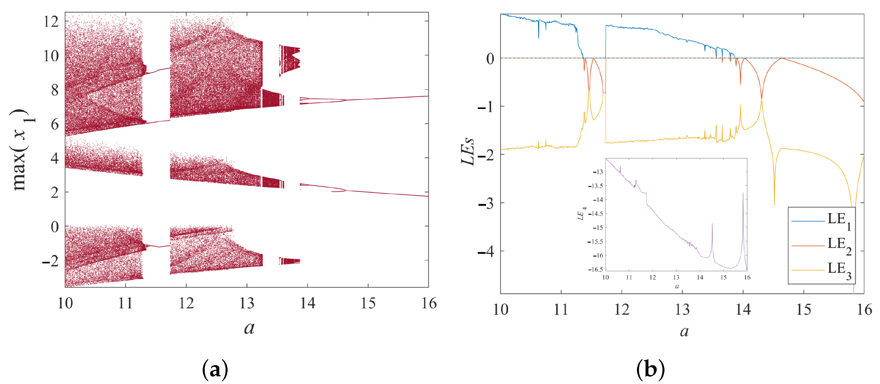
Consider the system parameters b = 15 , c = 2 , d = 10 , and initial values ( 0.5 , 0.5 , 0.6 , 0.6 ) . When the parameter a is varied, Figure 3a shows the bifurcation diagram of state variable x 1 versus parameter a. It can be observed that chaotic and periodic windows alternate. Additionally, the Lyapunov Exponent spectra (LEs) in Figure 3b confirm the same conclusion, consistent with the bifurcation diagram.
To facilitate the study of the attractor types as the system parameter a varies, Figure 4 shows the chaotic attractors under different values of a. It is observed that as the parameter a increases, Figure 4a displays a symmetric period-2 attractor, while Figure 4b shows a symmetric double-scroll chaotic attractor. Subsequently, an asymmetric double-scroll chaotic attractor appears, as shown in Figure 4c. In Figure 4d, when a = 13.7 , two non-symmetric multi-period attractors are observed. Figure 4e demonstrates a period-2 double-scroll attractor when a = 14.2 . Finally, when the system parameter a > 15 , the system enters a periodic state, as shown in Figure 4f. Therefore, under varying parameter a, the system exhibits multiple attractors. The evolution of attractors with respect to parameter a is shown in Table 2.

3.1.2. Dynamical Behavior Under Varying Parameter b

Consider the system parameters a = 10 , c = 2 , d = 10 , and initial values ( 0.5 , 0.5 , 0.6 , 0.6 ) . When the parameter b is varied, numerical simulations yield the bifurcation diagram of the state variable x 1 and the LEs as shown in Figure 5a and Figure 5b, respectively. As the parameter b increases, the system exhibits a period-doubling bifurcation behavior, with the bifurcation point occurring around b = 5 . Additionally, the LEs plot in Figure 5b demonstrates that the numerical simulation results are consistent with the observed dynamical behavior.
To reveal the characteristics of the system’s attractor types under changes in parameter b, the system’s attractor types are plotted for b = 4 , b = 5 , and b = 8 as shown in Figure 6. This further illustrates the rich dynamical behavior of the system.
As shown in Figure 6c, the chaotic attractor exhibits a double-scroll shape resembling the Lorenz attractor. And the calculated value D L = 2.2326 confirms that the attractor possesses a non-integer fractal structure, which is a hallmark of chaotic dynamics and consistent with the folding and symmetry behavior typical of Lorenz-like attractors. The presence of such attractors demonstrates the system’s rich nonlinear characteristics and further supports the claim of multistability and symmetry-breaking phenomena.

3.1.3. Dynamical Behavior Under Varying Parameter c

Similarly, by choosing parameters a = 10 , b = 15 , d = 10 , and the initial values x 0 = ( 0.5 , 0.5 , 0.6 , 0.6 ) , the bifurcation diagram with parameter c as a variable is plotted as shown in Figure 7a. It is observed that the system exhibits alternating chaos and periodic windows. A bifurcation occurs when c = 1.11 . As c increases beyond c > 1.21 , the system enters a chaotic state, with a brief periodic window within the chaotic window. Additionally, by further plotting the LEs as shown in Figure 7b, the observed dynamical behavior is consistent with the results of the bifurcation diagram.

3.1.4. Dynamical Behavior Under Varying Parameter d

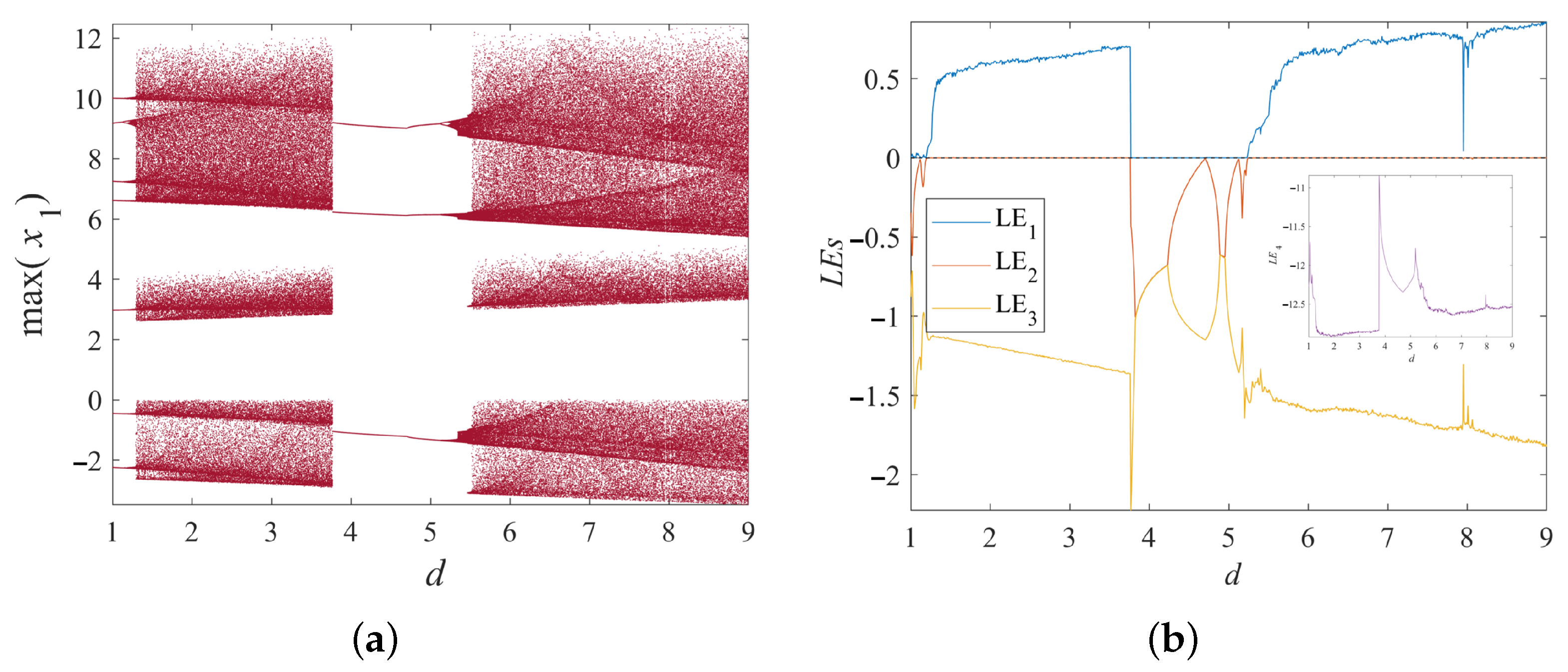
When considering the parameter d ( 1 , 9 ) , a = 10 , b = 15 , c = 2 , the system’s dynamic behavior is studied. Figure 8 shows the bifurcation diagram and the LEs with d as a variable. Two chaotic windows are observed, specifically in the d ( 1 , 3.7 ) and d ( 5.3 , 9 ) , while the system remains in periodic states in other parameter ranges.

3.2. Dynamics Complexity

This paper adopts contour plots for analysis to study the chaos map of system (1) under the dual parameter variation. Compared to the single-parameter variation method with fixed parameters, although the calculation of contour plots for dual parameter variation is more complex, it provides more information about the system’s complexity. It better reveals its dynamic behavior on a macroscopic level.
Considering system parameters a ( 10 , 16 ) and b ( 4 , 8 ) , we generate two-dimensional contour plots to visualize the system’s dynamical complexity under different parameter combinations. Figure 9 presents the results based on the Permutation Entropy (PE) and Network Permutation Entropy (NPE) algorithms, where brighter (yellow) regions indicate higher complexity. Figure 9a shows the entropy-based complexity landscape derived from the PE algorithm, reflecting the system’s behavioral complexity as parameters a and b vary. A small yellow region can be observed, suggesting that the system exhibits higher dynamical complexity within that parameter subspace. Figure 9b illustrates the corresponding complexity diagram obtained using the NPE algorithm. Compared to PE, the NPE-based landscape reveals fewer high-complexity regions, indicating that NPE may be less sensitive in capturing the full range of the system’s complex dynamical behavior.
By comparing the results of the two algorithms, we can conclude that the PE algorithm is more effective in describing the system’s high complexity regions and is better at accurately revealing the system’s complex behavior.

4. System Circuit Implementation

4.1. System Simulation Circuit Implementation

According to existing studies, chaotic circuits are crucial in engineering applications. Additionally, circuit implementation can verify the feasibility of theoretical models. Therefore, this section will discuss the circuit implementation of the chaotic system.
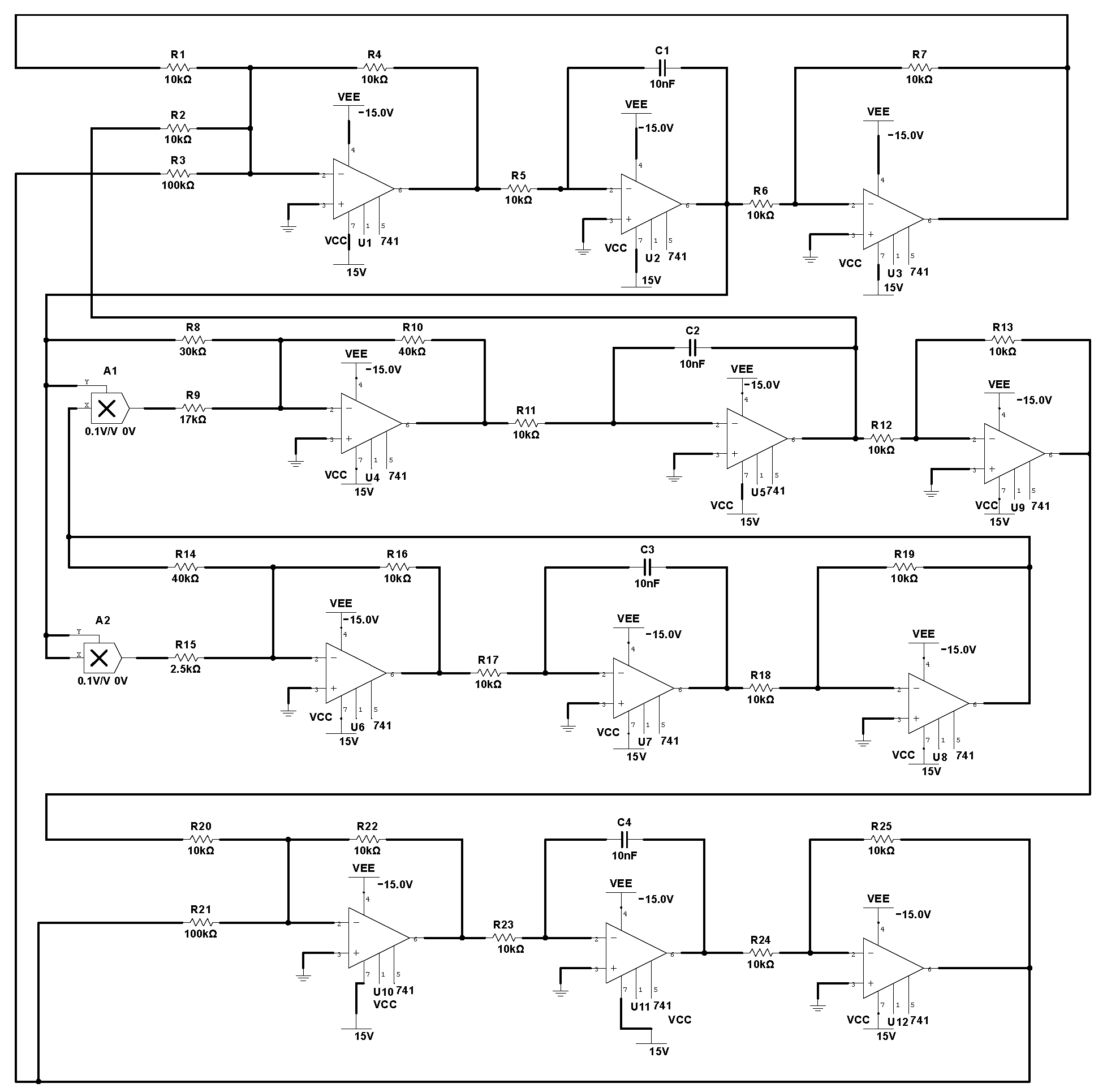
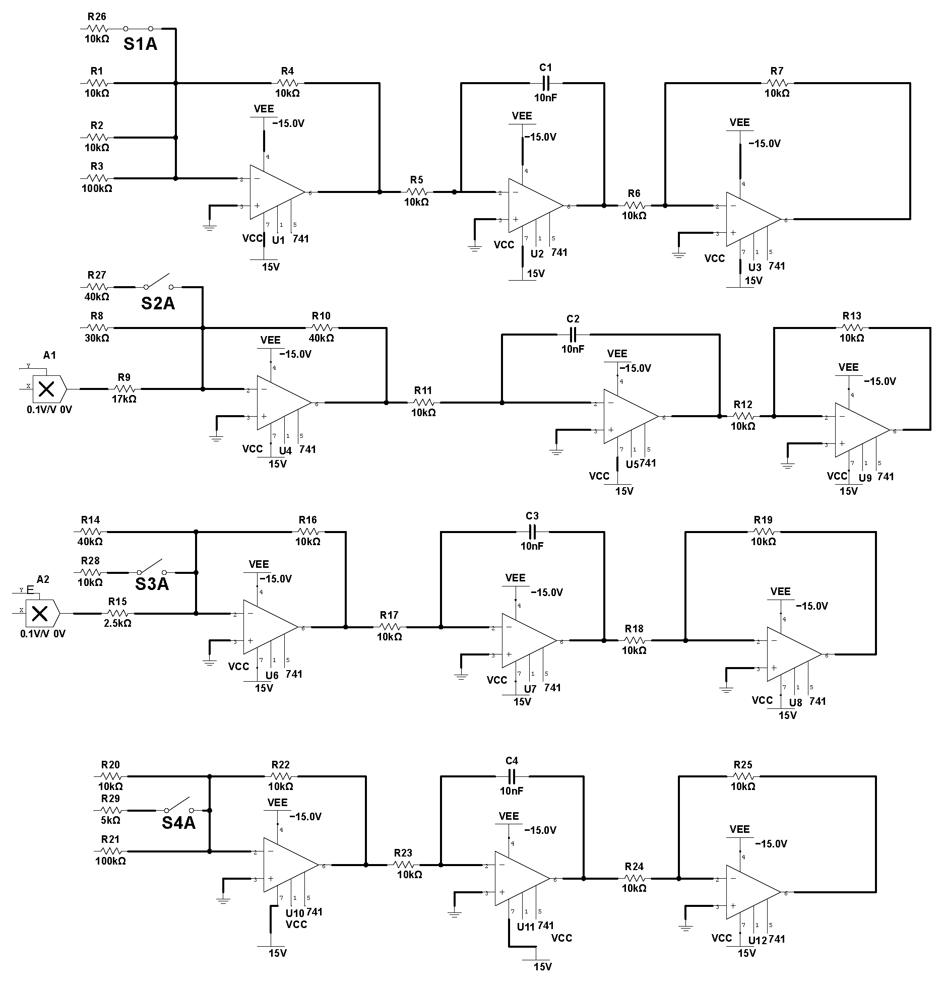
The equivalent circuit of system (1) in Figure 10 employs R 1 = 10 k Ω , R 2 = 10 k Ω , R 3 = 100 k Ω , R 4 = 10 k Ω , R 5 = 10 k Ω , R 6 = 10 k Ω , R 7 = 10 k Ω , R 8 = 30 k Ω , R 9 = 17 k Ω , R 10 = 40 k Ω , R 11 = 10 k Ω , R 12 = 10 k Ω , R 13 = 10 k Ω , R 14 = 40 k Ω , R 15 = 2.5 k Ω , R 16 = 10 k Ω , R 17 = 10 k Ω , R 18 = 10 k Ω , R 19 = 10 k Ω , R 20 = 10 k Ω , R 21 = 100 k Ω , R 22 = 10 k Ω , R 23 = 10 k Ω , R 24 = 10 k Ω , R 25 = 10 k Ω , C 1 = C 2 = C 3 = C 4 = 10 nF . This equivalent circuit consists of four channels, each composed of operational amplifier circuits, integrator operational amplifiers, and inverters. Two absolute value operation modules are added in the first and fourth channels. The circuit outputs of the four channels are denoted as x 1 , x 2 , x 3 and x 4 .
Based on the designed circuit, applying Kirchhoff’s circuit laws to the equivalent simulation circuit, the system’s equivalent circuit equations can be derived.
d x 1 d t = R 4 R 7 R 6 R 5 C 1 1 R 1 x 1 + x 2 1 R 3 x 4 d x 2 d t = R 10 R 13 R 12 R 11 C 2 1 R 8 x 1 + x 1 x 3 d x 3 d t = R 19 R 16 R 18 R 17 C 3 1 R 14 x 3 + x 1 2 d x 4 d t = R 25 R 22 R 24 R 23 C 4 1 R 20 x 2 x 4
The values of all circuit components are shown in the circuit schematic of Figure 10, with all operational amplifiers powered by a ± 15 V DC power supply. Figure 11 presents the chaotic attractor results of the system simulation circuit, which are consistent with the results obtained from numerical simulation in Figure 1 for system (1). Beyond its circuit realization, the proposed system’s complexity and structural properties make it a promising candidate for applications in secure communications, pseudo-random signal generation, and nonlinear system benchmarking.

4.2. Feedback Control

Consider a general nonlinear system as
d X d t = F ( X ) K X
where F = ( f 1 , f 2 , , f n ) T is the n-dimensional vector of nonlinear functions, X = ( x 1 , x 2 , , x n ) T is the n-dimensional state vector, and K = diag ( k 1 , k 2 , , k n ) is the linear feedback control parameter. The controlled system (10) can be represented as
d x 1 d t = a ( x 2 x 1 ) x 4 k 1 x 1 d x 2 d t = b x 1 x 1 x 3 k 2 x 2 d x 3 d t = 2.5 x 3 + c x 1 2 k 3 x 3 d x 4 d t = d x 2 x 4 k 4 x 4
By selecting the system parameters as a = 10 , b = 15 , c = 2 , d = 10 and the initial values x 0 = ( 0 . 5 , 0 . 5 , 0 . 6 , 0 . 6 ) the Jacobian matrix of system (10) at the equilibrium P 0 ( 0 , 0 , 0 , 0 ) is obtained as
a k 1 a 0 1 b k 2 0 0 0 0 2.5 k 3 0 0 d 0 k 4 1
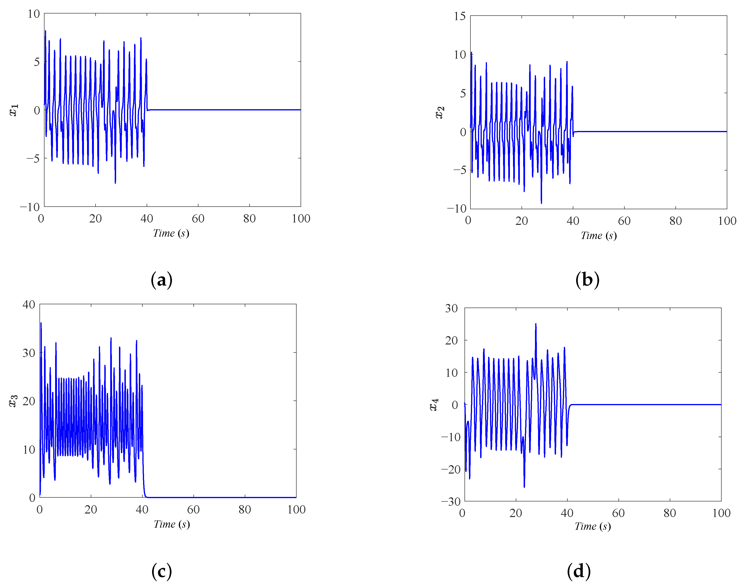
when k 1 = 10 , k 2 = 1 , k 3 = 1 , k 4 = 2 , according to the linear system stability theorem, the eigenvalues λ i of the controlled system satisfy a = b , where i = 1 , 2 , 3 , 4 . This indicates that the controlled system (10) can achieve chaotic control. The numerical simulation results, obtained by applying the control signal at t = 40 s , are shown in Figure 12.
Further, based on the controlled system (10), we designed a linear feedback control circuit as shown in Figure 13. According to the schematic of the circuit, when the switch is closed at t = 40 s , the feedback controller starts to take effect, adjusting the system’s state variables to achieve stability and control.
Through the circuit experiment on the system, we obtained the time-domain waveform of the state variables. To illustrate the system’s dynamic behavior, Figure 14 shows the time-domain waveforms of the states x 1 , x 2 , x 3 , x 4 , fully demonstrating the system’s behavior after adding the feedback control term.
From Figure 14, it can be observed that at t=40s after the linear feedback control signal is applied, the system’s state variables rapidly converge to zero. This indicates that the feedback control stabilized the system and stabilized its state. It is noteworthy that this experimental result entirely agrees with the numerical simulation results, which verifies the effectiveness of the designed feedback control circuit scheme. Furthermore, the experimental results also demonstrate that the system can effectively overcome chaotic behavior and achieve stable convergence of the state variables by choosing appropriate feedback control parameters.

5. FTSMS of System (1)

Sliding Mode Synchronization (SMS) is known for its robustness against parameter uncertainties and external disturbances [38]. It operates by forcing system trajectories onto a designed sliding surface and maintaining them on this surface, where the system exhibits desired dynamic behavior. SMS has been successfully applied in various engineering domains due to its simplicity and strong disturbance rejection capability [34,39]. In recent developments, FTSMS has emerged as a powerful extension, offering the additional advantage of convergence to equilibrium within a fixed time, independent of initial conditions.

5.1. Establishment of FTSMS Controller

Master–slave synchronization is a classic paradigm in chaotic systems research, aiming to drive a “slave” system to replicate the dynamics of a “master” system despite initial condition differences or external disturbances. Compared with the traditional methods, the FTSMS strategy proposed in this study aims to overcome these limitations by ensuring synchronization within a predefined time bound, independent of initial conditions.
The master system is governed by Equation (1). To design the synchronization control system, we first define the slave system, whose equation is given by:
x ˙ s 1 = a ( x s 2 x s 1 ) x s 4 + u 1 x ˙ s 2 = b x s 1 x s 1 x s 3 + u 2 x ˙ s 3 = 2.5 x s 3 + c x s 1 2 + u 3 x ˙ s 4 = d x s 2 x s 4 + u 4
where x s i ( i = 1 , 2 , 3 , 4 ) represents the state of the slave system, and u i ( i = 1 , 2 , 3 , 4 ) represents the control input. The synchronization error is defined as:
e 1 = x s 1 x 1 e 2 = x s 2 x 2 e 3 = x s 3 x 3 e 4 = x s 4 x 4
For e i ( i = s 1 , s 2 , s 3 , s 4 ) , its time derivative can be given by Equation (14):
e ˙ 1 = x ˙ s 1 x ˙ 1 e ˙ 2 = x ˙ s 2 x ˙ 2 e ˙ 3 = x ˙ s 3 x ˙ 3 e ˙ 4 = x ˙ s 4 x ˙ 4
By substituting the master system (1) and the slave system (12) into Equation (14), the dynamic equation for the synchronization error is obtained as follows:
e ˙ 1 = a ( e 2 e 1 ) e 4 + u 1 e ˙ 2 = b e 1 ( x s 1 x s 3 x 1 x 3 ) + u 2 e ˙ 3 = 2.5 e 3 + c ( x s 1 2 x 1 2 ) + u 3 e ˙ 4 = d e 2 e 4 + u 4
Simplify nonlinear terms x s 1 2 x 1 2 = ( x s 1 x 1 ) ( x s 1 + x 1 ) = e 1 ( x s 1 + x 1 ) . A fixed-time sliding surface is designed to achieve system synchronization control. The specific form is as follows:
s i = e i + 0 t K i | e i ( τ ) | α i sgn ( e i ( τ ) ) d τ
where K i > 0 , 0 < α i < 1 , i = 1 , 2 , 3 , 4 .
Theorem 1. 
The controller design for synchronization is applied to the slave system using four control inputs u i . The controller is designed as follows:
u 1 = a ( e 2 e 1 ) + e 4 K 1 | e 1 | α 1 sgn ( e 1 ) η ( | s 1 | β + | s 1 | 2 β ) sgn ( s 1 ) u 2 = b e 1 + ( x s 1 x s 3 x 1 x 3 ) K 2 | e 2 | α 2 sgn ( e 2 ) η ( | s 2 | β + | s 2 | 2 β ) sgn ( s 2 ) u 3 = 2.5 e 3 c e 1 ( x s 1 + x 1 ) K 3 | e 3 | α 3 sgn ( e 3 ) η ( | s 3 | β + | s 3 | 2 β ) sgn ( s 3 ) u 4 = d e 2 + e 4 K 4 | e 4 | α 4 sgn ( e 4 ) η ( | s 4 | β + | s 4 | 2 β ) sgn ( s 4 )
with η > 0 , 0 < β < 1 .
Proof. 
Step 1: Take Lyapunov function V i = 1 2 s i 2
V ˙ i = s i s ˙ i = s i e ˙ i + K i | e i | α i sgn ( e i )
Substitute control law
e ˙ i = K i | e i | α i sgn ( e i ) η ( | s i | β + | s i | 2 β ) sgn ( s i )
thus,
s ˙ i = η ( | s i | β + | s i | 2 β ) sgn ( s i )
Substituting the expression for s ˙ i , we can obtain:
V ˙ i = s i s ˙ i = s i η | s i | β + | s i | 2 β sgn ( s i ) = η | s i | β + 1 + | s i | 3 β = η 2 ( 1 + β ) 2 V i ( 1 + β ) 2 + 2 ( 3 β ) 2 V i ( 3 β ) 2
Define m = 1 β 2 and V ¯ i = 2 V i , then:
V ¯ ˙ i = 2 η ( V ¯ i 1 m + V ¯ i 1 + m )
assume there exists a time t f i such that V ¯ i = 0 . Then, by integrating from Equation (22), we obtain:
V ¯ i ( 0 ) V ¯ i ( t f i ) 1 V ¯ i 1 m + V ¯ i 1 + m d ( V ¯ i ) = 0 t f i 2 η d t
Subsequently, we can obtain:
t f s i = V ¯ i ( 0 ) V ¯ i ( t f s i ) 1 V ¯ i 1 m + V ¯ i 1 + m d V ¯ i 2 η = V ¯ i ( t f s i ) V ¯ i ( 0 ) 1 V ¯ i 1 m + V ¯ i 1 + m d V ¯ i 2 η = atan V i m ( 0 ) 2 m η atan V i m ( t f s i ) 2 m η
Considering that V ¯ i t f s i = 0 , we obtain:
t f s i = atan V i m ( 0 ) 2 m η
since V i m ( 0 ) is bounded, we have:
t f s i π 4 m η
therefore, the system’s sliding surface will stabilize within a fixed time, that is:
s i = 0 , t π 4 m η
Step 2: Assume the Lyapunov function H i = 1 2 e i 2 , and take its derivative. We obtain:
H ˙ i = e i e ˙ i = e i ( K i | e i | α i sgn ( e i ) ) = K i | e i | 1 + α i , 0 < α i < 1 = 2 K i | H i | 1 + α i 2
Although Equation (28) indicates that choosing any positive constant K i > 0 will ensure asymptotic stability of the error system in the ideal case. To ensure global fixed-time stability in such practical conditions, we further introduce a sufficient condition on K i , for K i , we present the following theorems simultaneously, and that the system converges to the synchronization manifold within a finite time regardless of initial conditions.
Theorem 2. 
For the closed-loop system Equation (12) under controller (17), global fixed-time stability is guaranteed if:
K i > | ϕ i | 2 μ ϵ 1 α i + η ϵ 1 α i
where, 0 < μ < 1 , ϵ > 0 , η > 0 , 0 < α i < 1 . ϕ i are linear coefficients from simplified error dynamics e ˙ i = ϕ i e i + u i stab . And the stabilizing controller is defined as u i s t a b = K i | e i | α i sgn ( e i ) .
Proof. 
First, construct the Lyapunov function V = 1 2 i = 1 4 ( s i 2 + e i 2 ) , and the time derivative is
V ˙ = i = 1 4 s i s ˙ i + e i e ˙ i
substitute Equation (20), we obtain
V ˙ = i = 1 4 s i η ( | s i | β + | s i | 2 β ) sgn ( s i ) + e i ϕ i e i K i | e i | α i sgn ( e i ) = η i = 1 4 | s i | β + 1 + | s i | 3 β + i = 1 4 ϕ i e i 2 K i | e i | 1 + α i
To ensure negativity of V ˙ , we need to upper-bound the ϕ i e i 2 term. Using the inequality
| ϕ i e i 2 | | ϕ i | 2 μ ϵ 1 α i | e i | 1 + α i , for | e i | ϵ
thus, the stability condition is
V ˙ η i = 1 4 | s i | β + 1 + | s i | 3 β + i = 1 4 | ϕ i | 2 μ ϵ 1 α i K i | e i | 1 + α i
Furthermore, to dominate the nonlinear term e i and improve convergence rate, we also require K i > η ϵ 1 α i . Thus
K i > | ϕ i | 2 μ ϵ 1 α i + η ϵ 1 α i
Tightening to Equation (28) ensures robustness. □
Based on Equation (26), it can be concluded that H ˙ i < 0 , and therefore, the system’s state will converge.

5.2. Numerical Simulation of FTSMS

When performing the numerical simulation for the system’s FTSMS, the system parameters are a = 10 , b = 15 , c = 2 , and d = 10 . The initial values for the master system are ( 0.5 , 0.5 , 0.6 , 0.6 ) , and the initial values for the slave system are ( 1 , 2 , 3 , 2 ) . The numerical simulation results for the synchronization error, control inputs, and sliding mode surface under the action of the controller (17) are shown in Figure 15.
As shown in Figure 15a, the synchronization error signals e 1 , e 2 , e 3 , e 4 rapidly converge to zero within approximately 2.23 s, indicating that the FTSMS controller achieves fixed-time synchronization as designed. Figure 15b shows the corresponding control inputs u 1 , u 2 , u 3 , u 4 , which remain smooth and bounded, confirming that the control effort is efficient and non-singular. Figure 15c illustrates the evolution of the sliding surfaces s 1 , s 2 , s 3 , s 4 , which also reach zero in finite time. This validates the theoretical sliding-mode design and demonstrates robust convergence to the synchronization manifold.

6. Conclusions

This paper proposed and investigated a novel chaotic system exhibiting complex dynamic behaviors. Through an analysis of the system’s order, parameters, and initial conditions, bifurcation diagrams and LEs were examined. The results demonstrate that variations in these factors lead to increasingly complex and diverse dynamics. In particular, parameter changes give rise to a wide range of behaviors, including periodic limit cycles, as well as single- and double-vortex chaotic attractors. Based on theoretical analysis, an equivalent circuit model corresponding to the system was established, and a simulated feedback control circuit was designed. The accuracy and feasibility of the circuit design were verified by comparison with numerical simulation results.
In addition, for the synchronization problem of this system, a fixed-time sliding mode synchronization control strategy was proposed. This control scheme ensures the system achieves synchronization within a predefined time interval, suppresses chaotic behaviors, and leads to system stability within the fixed time. Although progress was made in modeling and controlling the chaotic system in this paper, many issues remain for further exploration, including collaborative control of multi-agent systems, optimization problems based on chaotic systems, exploring the possibility of reduced-order or single-input controllers, and analyzing parameter uncertainties and disturbances in practical engineering applications. By delving deeper into these research directions, the application prospects of chaotic systems and their control strategies can be further enhanced, advancing the field toward more profound and widespread practical applications.

Author Contributions

Conceptualization, H.T. and X.Y.; methodology, J.L.; software, H.T. and X.X.; validation, Y.Z. and Z.W.; formal analysis, J.L. and H.T.; investigation, Z.W. and X.X.; resources, X.Y.; data curation, X.X. and H.T.; writing—original draft preparation, H.T. and J.L.; writing— review and editing, H.T. and Y.Z.; visualization, H.T. and X.X.; supervision, Z.W. and X.Y.; project administration, X.Y. and X.X.; funding acquisition, X.Y. and H.T. All authors have read and agreed to the published version of the manuscript.

Funding

This research was funded by the Sinopec Science and Technology Tackling Project (P18048-8), the Horizontal Project (2024610002012846), the Natural Science Basic Research Program of Shaanxi (2023-JC-QN-0088), the Scientific Research Program Funded by Shaanxi Provincial Education Department (23JK0700), and the Fund of the Youth Innovation Team of Shaanxi Universities.

Data Availability Statement

The original contributions presented in this study are included in the article. Further inquiries can be directed to the corresponding author.

Acknowledgments

The authors acknowledge the referees and the editor for carefully reading this paper and giving many helpful comments. The authors also express their gratitude to the reviewers for their insightful comments.

Conflicts of Interest

The authors declare no conflicts of interest. Author Xifeng Yi is employed by the Sinopec Shengli Oilfield Company. The authors declare that this study received funding from the Sinopec Science and Technology Tackling Project (P18048-3038). The funder was not involved in the study design, collection, analysis, interpretation of data, the writing of this article, or the decision to submit it for publication.

References

  1. Shinbrot, T.; Ditto, W.; Grebogi, C.; Ott, E.; Spano, M.; Yorke, J.A. Using the sensitive dependence of chaos (the ‘‘butterfly effect’’) to direct trajectories in an experimental chaotic system. Phys. Rev. Lett. 1992, 68, 2863. [Google Scholar] [CrossRef]
  2. Lorenz, E.N. Deterministic nonperiodic flow. J. Atmos. Sci. 1963, 20, 130–141. [Google Scholar] [CrossRef]
  3. Zolfaghari, B.; Koshiba, T. Chaotic image encryption: State-of-the-art, ecosystem, and future roadmap. Appl. Syst. Innov. 2022, 5, 57. [Google Scholar] [CrossRef]
  4. Mahmoud, E.E.; Trikha, P.; Jahanzaib, L.S.; Almaghrabi, O.A. Dynamical analysis and chaos control of the fractional chaotic ecological model. Chaos Solitons Fractals 2020, 141, 110348. [Google Scholar] [CrossRef]
  5. Wang, Z.; Parastesh, F.; Tian, H.; Jafari, S. Symmetric synchronization behavior of multistable chaotic systems and circuits in attractive and repulsive couplings. Integration 2023, 89, 37–46. [Google Scholar] [CrossRef]
  6. Boui A Boya, B.F.; Muni, S.S.; Echenausía-Monroy, J.L.; Kengne, J. Chaos, synchronization, and emergent behaviors in memristive hopfield networks: Bi-neuron and regular topology analysis. Eur. Phys. J. Spec. Top. 2024, 1–15. [Google Scholar] [CrossRef]
  7. Tian, H.; Wang, J.; Ma, J.; Li, X.; Zhang, P.; Li, J. Improved energy-adaptive coupling for synchronization of neurons with nonlinear and memristive membranes. Chaos Solitons Fractals 2025, 199, 116863. [Google Scholar] [CrossRef]
  8. dos Santos Oliveira, E.; Nackenhorst, U. Sparse polynomial chaos expansion for high-dimensional nonlinear damage mechanics. Probabilistic Eng. Mech. 2024, 75, 103556. [Google Scholar] [CrossRef]
  9. Zhang, P.; Hu, W.; Wang, Z.; Qiao, Z. Multi-Symplectic Simulation on Soliton-Collision for Nonlinear Perturbed Schrödinger Equation. J. Nonlinear Math. Phys. 2023, 30, 1467–1482. [Google Scholar] [CrossRef]
  10. Abdechiri, M.; Faez, K.; Amindavar, H.; Bilotta, E. The chaotic dynamics of high-dimensional systems. Nonlinear Dyn. 2017, 87, 2597–2610. [Google Scholar] [CrossRef]
  11. Liu, T.; Zhao, X.; Sun, P.; Zhou, J. A hybrid proper orthogonal decomposition and next generation reservoir computing approach for high-dimensional chaotic prediction: Application to flow-induced vibration of tube bundles. Chaos Interdiscip. J. Nonlinear Sci. 2024, 34, 033125. [Google Scholar] [CrossRef] [PubMed]
  12. Es-Sabry, M.; El Akkad, N.; Merras, M.; Satori, K.; El-Shafai, W.; Altameem, T.; Fouda, M.M. Securing images using high dimensional chaotic maps and DNA encoding techniques. IEEE Access 2023, 11, 100856–100878. [Google Scholar] [CrossRef]
  13. Zeng, Y.; Hu, H.; Shuai, Y. A general method for constructing high-dimensional chaotic maps with topological mixing on the global phase space. Chaos Solitons Fractals 2024, 182, 114818. [Google Scholar] [CrossRef]
  14. Adel, M.; Khader, M.M.; Algelany, S. High-dimensional chaotic Lorenz system: Numerical treatment using Changhee polynomials of the Appell type. Fractal Fract. 2023, 7, 398. [Google Scholar] [CrossRef]
  15. Qi, G.; Du, S.; Chen, G.; Chen, Z. On a four-dimensional chaotic system. Chaos Solitons Fractals 2005, 23, 1671–1682. [Google Scholar] [CrossRef]
  16. Ababneh, M. A new four-dimensional chaotic attractor. Ain Shams Eng. J. 2018, 9, 1849–1854. [Google Scholar] [CrossRef]
  17. Wang, X.; Feng, Y.; Chen, Y. A new four-dimensional chaotic system and its circuit implementation. Front. Phys. 2022, 10, 906138. [Google Scholar] [CrossRef]
  18. Halder, A.K.; Paliathanasis, A.; Leach, P.G. Noether’s theorem and symmetry. Symmetry 2018, 10, 744. [Google Scholar] [CrossRef]
  19. Strocchi, F. Symmetry Breaking; Springer: Berlin/Heidelberg, Germany, 2005; Volume 643. [Google Scholar]
  20. Kengne, J.; Mogue, R.L.T.; Fozin, T.F.; Telem, A.N.K. Effects of symmetric and asymmetric nonlinearity on the dynamics of a novel chaotic jerk circuit: Coexisting multiple attractors, period doubling reversals, crisis, and offset boosting. Chaos Solitons Fractals 2019, 121, 63–84. [Google Scholar] [CrossRef]
  21. Qi, G.; Chen, G.; Zhang, Y. On a new asymmetric chaotic system. Chaos Solitons Fractals 2008, 37, 409–423. [Google Scholar] [CrossRef]
  22. Pham, V.T.; Velichko, A.; Van Huynh, V.; Radogna, A.V.; Grassi, G.; Boulaaras, S.M.; Momani, S. Analysis of memristive maps with asymmetry. Integration 2024, 94, 102110. [Google Scholar] [CrossRef]
  23. Hubler, A. Adaptive control of chaotic system. Helv. Phys. Acta 1989, 62, 343–346. [Google Scholar]
  24. Ott, E.; Grebogi, C.; Yorke, J.A. Controlling chaos. Phys. Rev. Lett. 1990, 64, 1196. [Google Scholar] [CrossRef] [PubMed]
  25. Pecora, L.M.; Carroll, T.L. Synchronization in chaotic systems. Phys. Rev. Lett. 1990, 64, 821. [Google Scholar] [CrossRef]
  26. Chen, G. Control and anticontrol of chaos. In Proceedings of the 1997 1st International Conference, Control of Oscillations and Chaos Proceedings (Cat. No. 97TH8329), St. Petersburg, Russia, 27–29 August 1997; Volume 2, pp. 181–186. [Google Scholar]
  27. Wang, J.; Gao, J.; Ma, X. Synchronization control of cross-strict feedback hyperchaotic system based on cross active backstepping design. Phys. Lett. A 2007, 369, 452–457. [Google Scholar] [CrossRef]
  28. Feng, X.Q.; Shen, K. Controlling hyperchaos and periodic synchronization in DOPO with parameter modulated by an external periodic signal. Chaos Solitons Fractals 2008, 35, 506–511. [Google Scholar] [CrossRef]
  29. Effati, S.; Saberi-Nadjafi, J.; Nik, H.S. Optimal and adaptive control for a kind of 3D chaotic and 4D hyper-chaotic systems. Appl. Math. Model. 2014, 38, 759–774. [Google Scholar] [CrossRef]
  30. Li, K.; Li, R.; Cao, L.; Feng, Y.; Onasanya, B.O. Periodically intermittent control of Memristor-based hyper-chaotic bao-like system. Mathematics 2023, 11, 1264. [Google Scholar] [CrossRef]
  31. Zhang, L.; Wang, Y.; Hou, Y.; Li, H. Fixed-time sliding mode control for uncertain robot manipulators. IEEE Access 2019, 7, 149750–149763. [Google Scholar] [CrossRef]
  32. Moulay, E.; Léchappé, V.; Bernuau, E.; Defoort, M.; Plestan, F. Fixed-time sliding mode control with mismatched disturbances. Automatica 2022, 136, 110009. [Google Scholar] [CrossRef]
  33. Rezaie, A. Sliding Mode Control for Chaotic Systems with Unknown Uncertainties. Int. J. Ind. Electron. Control Optim. 2024, 7, 53–60. [Google Scholar]
  34. Chan, J.C.L.; Lee, T.H.; Tan, C.P. Secure communication through a chaotic system and a sliding-mode observer. IEEE Trans. Syst. Man, Cybern. Syst. 2020, 52, 1869–1881. [Google Scholar] [CrossRef]
  35. Vaseghi, B.; Pourmina, M.A.; Mobayen, S. Secure communication in wireless sensor networks based on chaos synchronization using adaptive sliding mode control. Nonlinear Dyn. 2017, 89, 1689–1704. [Google Scholar] [CrossRef]
  36. Abou El Qassime, A.; Nhaila, H.; Bahatti, L.; Zayrit, S. Advanced speech encryption method leveraging a hidden hyperchaotic attractor and its synchronization with robust adaptive sliding mode control. Nonlinear Dyn. 2025, 113, 15553–15578. [Google Scholar] [CrossRef]
  37. Kuznetsov, Y.A.; Kuznetsov, I.A.; Kuznetsov, Y. Elements of Applied Bifurcation Theory; Springer: Berlin/Heidelberg, Germany, 1998; Volume 112. [Google Scholar]
  38. Yau, H.T. Design of adaptive sliding mode controller for chaos synchronization with uncertainties. Chaos Solitons Fractals 2004, 22, 341–347. [Google Scholar] [CrossRef]
  39. Serrano, F.E.; Pham, V.T. Fractional memristive-discrete neural network: Projective terminal sliding mode synchronization. Eur. Phys. J. Spec. Top. 2025, 1–14. [Google Scholar] [CrossRef]
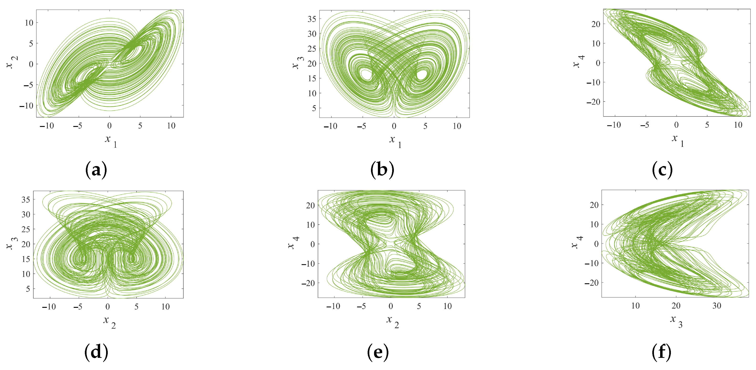
Figure 1. The chaotic attractor of system (1): (a) phase portrait of the x 1 x 2 plane; (b) phase portrait of the x 1 x 3 plane; (c) phase portrait of the x 1 x 4 plane; (d) phase portrait of the x 2 x 3 plane; (e) phase portrait of the x 2 x 4 plane; (f) phase portrait of the x 3 x 4 plane.
Symmetry 17 01252 g001
Figure 2. Chaotic attractor and poincaré section of system (1): (a) phase portrait of the system in the x 1 x 2 x 3 space; (b) poincaré section at x 3 = 18 .
Symmetry 17 01252 g002
Figure 3. Bifurcation diagram and LEs under varying system parameter a: (a) bifurcation diagram; (b) LEs.
Symmetry 17 01252 g003
Figure 4. Attractor types in system (1) on the x 1 x 3 plane under different parameters a: (a) period-2 attractor for a = 11.5 ; (b) symmetric double-scroll chaotic attractor for a = 13.1 ; (c) double-scroll chaotic attractor for a = 13.3 ; (d) double-scroll multi-periodic attractor for a = 13.7 ; (e) double-scroll period-2 attractor for a = 14.2 ; (f) double-scroll period-1 attractor for a = 15 .
Symmetry 17 01252 g004aSymmetry 17 01252 g004b
Figure 5. Bifurcation diagram and LEs under varying system Parameter b. (a) Bifurcation diagram; (b) LEs.
Symmetry 17 01252 g005
Figure 6. Attractor types in system (1) on the x 1 x 3 plane under different parameters b: (a) symmetric period-1 attractor for b = 4 ; (b) double-scroll quasi-periodic attractor for b = 5 ; (c) symmetric double-scroll chaotic attractor for b = 8 .
Symmetry 17 01252 g006
Figure 7. Bifurcation diagram and LEs under varying system parameter c. (a) Bifurcation diagram; (b) LEs.
Symmetry 17 01252 g007
Figure 8. Bifurcation diagram and LEs under varying system parameter d: (a) bifurcation diagram; (b) LEs.
Symmetry 17 01252 g008
Figure 9. Entropy-based complexity diagram with changing system parameters a and b: (a) constructed using PE; (b) constructed using NPE.
Symmetry 17 01252 g009
Figure 10. The schematic diagram of system (1) simulation circuit.
Symmetry 17 01252 g010
Figure 11. The chaotic attractor of system (1) simulation circuit: (a) x 1 x 2 diagram; (b) x 1 x 3 diagram; (c) x 1 x 4 diagram; (d) x 2 x 3 diagram; (e) x 2 x 4 diagram; (f) x 3 x 4 diagram.
Symmetry 17 01252 g011
Figure 12. Time-domain waveform plots of system (10) under feedback control, obtained from numerical simulations: (a) time-domain waveform of state x 1 ; (b) time-domain waveform of state x 2 ; (c) time-domain waveform of state x 3 ; (d) time-domain waveform of state x 4 .
Symmetry 17 01252 g012
Figure 13. System (10) feedback control circuit schematic diagram.
Symmetry 17 01252 g013
Figure 14. Time-domain waveform diagram of the system’s feedback control circuit: (a) time-domain waveform of state x 1 ; (b) time-domain waveform of state x 2 ; (c) time-domain waveform of state x 3 ; (d) time-domain waveform of state x 4 .
Symmetry 17 01252 g014
Figure 15. The numerical simulation results of FTSMS. (a) Synchronization error curve of the system; (b) Control input curve of the system; (c) Sliding mode surface curve of the system.
Symmetry 17 01252 g015
Table 1. Correspondence table of iteration steps, LEs, and trends.
Iterations λ 1 λ 2 λ 3 λ 4 Trend
0– 10 4 1.82 0.05 3.71 11.56 Transition state
10 4 10 5 1.45 0.01 4.83 9.61 Convergent state
10 5 10 6 1.38 0.003 5.92 8.46 Stable state
Table 2. Attractor Evolution (Parameter a Variation).
aAttractor TypeSymmetry
11.5Symmetric Period-2 AttractorSymmetric
13.1Symmetric Double-Scroll ChaosSymmetric
13.1 → 13.3Asymmetric Double-Scroll ChaosSymmetry Breaking
13.7Asymmetric Multi-Period AttractorBroken State
Disclaimer/Publisher’s Note: The statements, opinions and data contained in all publications are solely those of the individual author(s) and contributor(s) and not of MDPI and/or the editor(s). MDPI and/or the editor(s) disclaim responsibility for any injury to people or property resulting from any ideas, methods, instructions or products referred to in the content.