Article

Studying Homoclinic Chaos in a Class of Piecewise Smooth Oscillators: Melnikov’s Approach, Symmetry Results, Simulations and Applications to Generating Antenna Factors Using Approximation and Optimization Techniques

1
Faculty of Mathematics and Informatics, University of Plovdiv Paisii Hilendarski, 24, Tzar Asen Str., 4000 Plovdiv, Bulgaria
2
Institute of Mathematics and Informatics, Bulgarian Academy of Sciences, Acad. G. Bonchev Str., Bl. 8, 1113 Sofia, Bulgaria
3
Faculty of Mathematics and Informatics, Sofia University “St. Kliment Ohridski”, 5, James Bourchier Blvd., 1164 Sofia, Bulgaria
*
Author to whom correspondence should be addressed.
Symmetry 2025, 17(7), 1144; https://doi.org/10.3390/sym17071144
Submission received: 21 June 2025 / Revised: 11 July 2025 / Accepted: 14 July 2025 / Published: 17 July 2025
(This article belongs to the Section Mathematics)

Abstract

In this paper, we provide a novel extended mixed differential model that is appealing to users because of its numerous free parameters. The motivation of this research arises from the opportunity for a general investigation of some outstanding classical and novel dynamical models. The higher energy levels known in the literature can be governed by appropriately added correction factors. Furthermore, the different applications of the considered model can be achieved only after a proper parameter calibration. All these necessitate the use of diverse optimization and approximation techniques. The proposed extended model is especially useful in the important field of decision making, namely the antenna array theory. This is due to the possibility of generating high-order Melnikov polynomials. The work is a natural continuation of the authors’ previous research on the topic of chaos generation via the term x | x | a 1 . Some specialized modules for investigating the dynamics of the proposed oscillators are provided. Last but not least, the so-defined dynamical model can be of interest for scientists and practitioners in the area of antenna array theory, which is an important part of the decision-making field. The stochastic control of oscillations is also the subject of our consideration. The underlying distributions we use may be symmetric, asymmetric or strongly asymmetric. The same is true for the mass in the tails, too. As a result, the stochastic control of the oscillations we purpose may exhibit a variety of possible behaviors. In the final section, we raise some important issues related to the methodology of teaching Master’s and PhD students.

1. Introduction

Numerous oscillatory natural phenomena that arise in a range of fields, including engineering, quantum optics, acoustics, hydrodynamics, electronics, and mechanics, have potential and are portrayed by a general escape nonlinear oscillator model. Using nonlinear damping conditions as a power series on the speed reads, Sanjuan [1] examines the equation of movement for the sinusoidal-driven escape oscillator:
x ¨ + p = 1 n β x ˙ | x ˙ | p 1 + x x 2 = F sin ω t ,
where β is the damping level, p is the damping exponent, and F and ω are the forcing amplitude and the frequency of the outer disturbance, respectively. The nonlinearly damped general escape oscillator and nonlinear vessel trundling reply are shown as follows:
d x d t = y d y d t = j = 1 m a j x j + p = 1 n c p y | y | p 1 + F cos ω t
with initial conditions x ( t 0 ) = x 0 ; y ( t 0 ) = y 0 . The authors of [2] have thoroughly examined the effects of the damping level on the escape oscillator’s basin bifurcation models and the rational response of the steady-state decisions. A significant amount of diverse literature exists on this subject. To find further pertinent research, we direct the reader to [2,3,4,5,6,7]. Several extended differential models can be found in [8,9,10]. Tang, Man, Zhong, and Chen [11] investigate the nature of the factor x | x | as a chaos producer in a non-self-governing differential model. In particular, the following model is considered:
d x d t = y d y d t = a x b x | x | ϵ ξ y c sin ( ω t )
with initial conditions x ( t 0 ) = x 0 ; y ( t 0 ) = y 0 . The coefficients ϵ ξ and ϵ c are tiny parameters for ϵ 1 . In [12], the authors examine the generalized Duffing-type model with a fractional order nonlinear term.
d x d t = y d y d t = x x | x | a 1 + ϵ γ cos ( ω t ) δ y
beginning with the constraints x ( t 0 ) = x 0 ; y ( t 0 ) = y 0 , where a > 1 is either a fraction or an integer. The coefficients ϵ γ and ϵ δ are tiny parameters for ϵ 1 . Equation (4) (see [13,14,15]) represents the oscillatory motion of a buckled beam with simply supported or hinged ends for the modal displacement x ( t ) . The authors of [16] provide several control strategies to stabilize the chaotic behavior of a fractional piecewise-smooth oscillator. The topic: chaos generation via x | x | a 1 , Melnikov’s approach and simulations are discussed for a modified model in the article [17]. More precisely, the authors investigate the dynamics of the new extended oscillator class listed below [17]:
d x d t = y d y d t = x x | x | a 1 + ϵ j = 1 N a j cos ( j ω t ) A y ,
in this case, 0 ϵ < 1 , A > 0 , a i 0 , i = 1 , 2 , , N , and N is an integer. Ref. [18] considers the use of tiny parametrical perturbations to divert homoclinic chaos in a class of piecewise smooth oscillators to stable periodic orbits. More precisely, the authors explore the following extended differential model [18]:
d x d t = y d y d t = a x b x | x | α 1 + ϵ γ cos ( ω t ) δ + F sin ( ω t + Ψ ) y ,
where F is the amplitude, ω is the angular frequency, and Ψ is the phase position of the sinusoidal control signal.Other interesting results can be found in [19,20,21]. In the titles cited above, the reader can find additional useful literature on the topic under consideration. In certain instances, after calculating the Melnikov functions, researchers discover that the homoclinic orbits are so complicated that the expressions of the Melnikov functions cannot be solved analytically. Numerical algorithms are typically suggested and applied for this aim. In article [17], we noted that model (6) could possibly be investigated at a higher energy level by appropriately adding correction factors. Since symmetry and conditional symmetry are fundamental concepts, a thorough analysis of both is presented in [22,23].
In this paper, we propose a new extended mixed model based on the differential models mentioned above. Studies are examined in the context of Melnikov’s methodology [24]. The derived theoretical results are illustrated and validated by many numerical examples. The used parameters are chosen in a way to demonstrate the possible behavior of the dynamical system in its entirely. These experiments are performed via the software platforms of CAS Mathematics and MATLAB 2024a. We also introduce some dedicated modules for studying the behavior of these fictitious oscillators. For more details, see [25]. The results obtained can be included into a much wider scientific computing application.
Last but not least, the so-defined dynamical model can be of interest for scientists and practitioners in the area of antenna array theory—an important part of the decision-making field. Briefly said, the antenna arrays consist of many single antennas, whose proper positions are of outstanding importance for optimal results. The opportunities that the proposed oscillator model gives for a proper direction of the radiated signal as well as for the control of the frequency and amplitude determine the large applicability of the results derived. We refer to the works of [26,27,28,29] and references therein. See also [30].
The outline of this paper is as follows. In Section 2, we provide our model. Section 3 examines investigations in the context of Melnikov’s methodology. Section 4 presents a few simulations. Stochastic control on the oscillations is considered in Section 5. Section 6 discusses one potential use for Melnikov functions, which is the modeling and synthesis of antenna factors using approximation and optimization procedures. Section 7 brings us to a conclusion.

2. The Model

In this article, we will consider the next new class of extended mixed oscillators, which is a modification of the differential model (6):
d x d t = y d y d t = a x b x | x | α 1 + ϵ j = 1 N a j cos ( j ω t ) A y | y | p 1 ,
where p is the damping parameter, N is an integer, 0 ϵ < 1 , A > 0 , and a i 0 , i = 1 , 2 , , N . The collection of levels is formed by
1 2 y 2 a 2 x 2 + b x 2 | x | α 1 α + 1 = 0 .
The two homoclinic orbits Γ + ( t ) = ( x 0 ( t ) , y 0 ( t ) ) and Γ ( t ) = Γ + ( t ) make up this structure. We take into account the orbit
x 0 ( t ) = a ( α + 1 ) 2 b 1 α 1 ( sech ( a ( α 1 ) 2 t ) ) 2 α 1 y 0 ( t ) = a a ( α + 1 ) 2 b 1 α 1 ( sech ( a ( α 1 ) 2 t ) ) 2 α 1 tanh ( a ( α 1 ) 2 t )
(some details can be found in [18]).

3. Reflections in View of Melnikov’s Methodology

The Melnikov function can be used to determine the transverse intersection of the stable and unstable manifolds and offers a leading order distance measurement between the stable and unstable manifolds when ϵ 0 . For model (8), the Melnikov integral is by definition given by
M ( t 0 ) = y 0 ( t ) j = 1 N a j cos ( j ω ( t + t 0 ) ) A y 0 ( t ) | y 0 ( t ) | p 1 d t ,
where Equations (8) define the functions x 0 ( t ) and y 0 ( t ) . Because the parameters that appear in the proposed differential model are subject to certain physical and practical limitations, the problem of finding the root of M ( t 0 ) is more interesting from a numerical point of view. For some t 0 and some sets of parameters, it is widely known that chaos results if M ( t 0 ) = 0 and d M ( t 0 ) d t 0 0 .
We are able to demonstrate the next claims.
Proposition 1.
If α = 2 , p = 2 , N = 1 , a = b = 1 , and | Im ( ω ) | < 1 , then the equation’s solutions are the roots of the Melnikov function M ( t 0 ) .
M ( t 0 ) = 9 A 16 + 6 a 1 π ω 2 csch ( π ω ) sin ( t 0 ω ) = 0 .
Example 1.
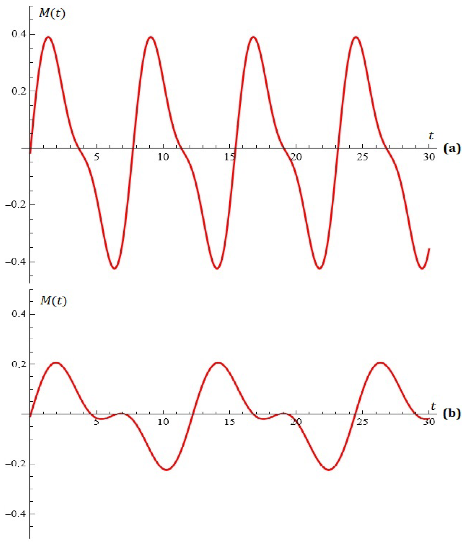
The equation M ( t 0 ) = 0 for α = 2 , p = 2 , N = 1 , a = b = 1 , A = 0.1 , ω = 0.25 , a 1 = 0.6 is depicted in Figure 1a.
Example 2.
The equation M ( t 0 ) = 0 for α = 2 , p = 2 , N = 1 , a = b = 1 , A = 0.3 , ω = 0.13 , a 1 = 0.222 is depicted in Figure 1b. The root t 0 = 12 has a multiplicity of two.
Proposition 2.
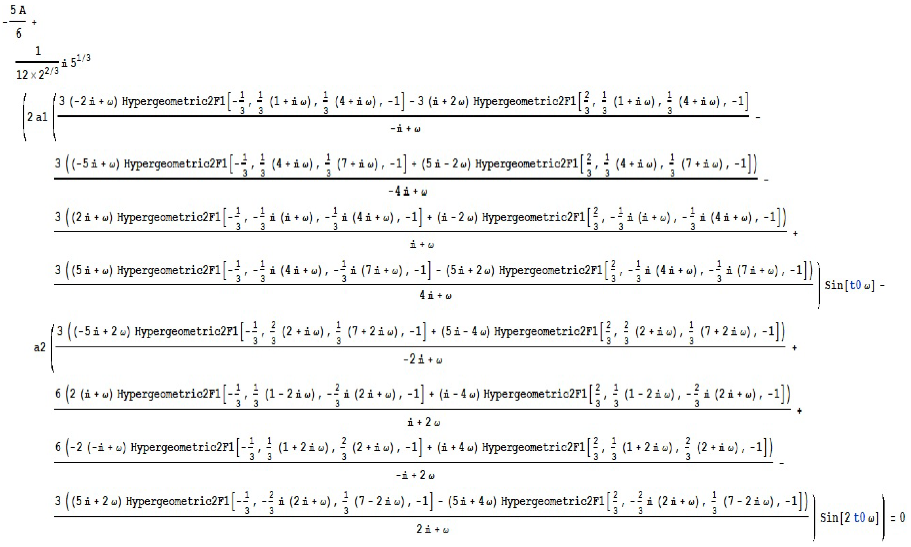
The solutions of the equation in Figure 2 are the roots of the Melnikov function M ( t 0 ) if α = 4 , p = 2 , N = 2 , a = b = 1 , and | Im ( ω ) | < 1 2 .
Since it is stated in terms of the hypergeometric function 2F1 [ . , . , . , . ] and requires the user to execute several operations (such as the operator S i m p l i f y [ % ] ), the explicit representation of M ( t 0 ) in this instance (and for high values of the parameter N) is time consuming. Figure 2 illustrates the calculation of M ( t 0 ) using CAS Mathematica.
Example 3.
The equation M ( t 0 ) = 0 for α = 4 , p = 2 , N = 2 , a = b = 1 , A = 0.02 , ω = 0.815 , a 1 = 0.2 , a 2 = 0.1 is depicted in Figure 3a.
Example 4.
The equation M ( t 0 ) = 0 for α = 4 , p = 2 , N = 2 , a = b = 1 , A = 0.01 , ω = 0.515 , a 1 = 0.1 , a 2 = 0.058 is depicted in Figure 3b.
Proposition 3.
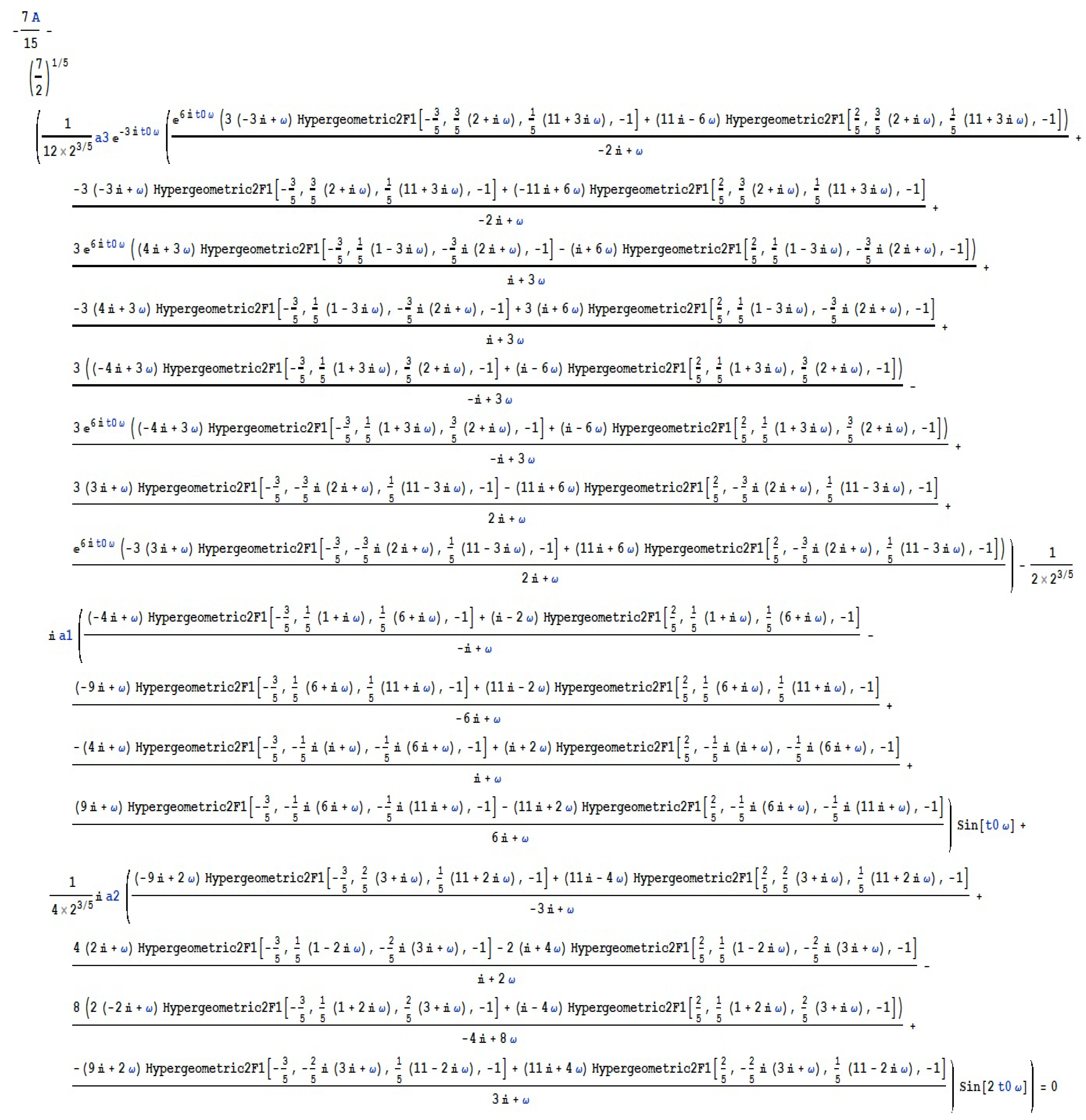
The solutions of the equation in Figure A1 are the roots of the Melnikov function M ( t 0 ) if α = 6 , p = 4 , N = 3 , and | Im ( ω ) | < 1 3 .
The reader can develop Melnikov’s criterion for the occurrence of the intersection between the disturbed and unperturbed separatrixes using Propositions 1–3.
Example 5.
The equation M ( t 0 ) = 0 for α = 6 , p = 4 , N = 3 , a = b = 1 , A = 0.02 , ω = 0.815 , a 1 = 0.2 , a 2 = 0.1 , a 3 = 0.2 is depicted in Figure 4a.
Example 6.
The equation M ( t 0 ) = 0 for α = 6 , p = 4 , N = 3 , a = b = 1 , A = 0.02 , ω = 0.586 , a 1 = 0.2 , a 2 = 0.1 , a 3 = 0.2 is depicted in Figure 4b.

4. Some Simulations

Here, we will focus on some fascinating simulations:
Example 7.
For given α = 4 ; p = 2 ; N = 2 ; a = 0.96 ; b = 1.1 ; A = 0.1 ; ϵ = 0.0095 ; ω = 0.1 ; a 1 = 0.07 ; a 2 = 0.8 , Figure 5 shows the simulations on the system (7) for x 0 = 0.1 ; y 0 = 0.1 .
Example 8.
For given α = 6 ; p = 4 ; N = 3 ; a = 0.05 ; b = 0.7 ; A = 0.12 ; ϵ = 0.0095 ; ω = 0.1 ; a 1 = 0.07 ; a 2 = 0.8 ; a 3 = 0.2 , Figure 6 shows the simulations on the system (7) for x 0 = 0.1 ; y 0 = 0.1 .
Example 9.
For given α = 8 ; p = 6 ; N = 4 ; a = 0.55 ; b = 0.25 ; A = 0.1 ; ϵ = 0.0095 ; ω = 0.11 ; a 1 = 0.075 ; a 2 = 0.82 ; a 3 = 0.23 ; a 4 = 0.11 , Figure 7 shows the simulations on the system (7) for x 0 = 0.1 ; y 0 = 0.1 .
Example 10.
For given α = 10 ; p = 8 ; N = 6 ; a = 0.05 ; b = 0.7 ; A = 0.12 ; ϵ = 0.0095 ; ω = 0.1 ; a 1 = 0.07 ; a 2 = 0.8 ; a 3 = 0.2 ; a 4 = 0.05 ; a 5 = 0.4 ; a 6 = 0.1 , Figure 8 shows the simulations on the system (7) for x 0 = 0.1 ; y 0 = 0.1 .

5. Stochastic Control on the Oscillations

In this section, we present an approach for a possible control on the oscillations. Suppose that the constants a j from model (7) are the probabilities of some distribution defined on the domain 1 , 2 , . . . , N . We may assume this without any restrictions because we can scale the system with the term j = 1 N a j , and a j 0 . Let the characteristic function of this distribution be Ψ x . Also, let ξ be a random variable distributed via the corresponding low and the symbol E be for the mathematical expectation. Thus, we have P ξ = k = a k j = 1 N a j , whereby P is denoted the probability measure. Thus, using the following well-known exponential presentation of the cos function
cos x = e i x + e i x 2 ,
we may transform the y-dynamics in (7) into
d y d t = a x b x x α 1 + ϵ j = 1 N a j cos j ω t A y y p 1 = a x b x x α 1 + ϵ E e i ω t ξ + E e i ω t ξ 2 A y y p 1 = a x b x x α 1 + ϵ Ψ ω t + Ψ ω t 2 A y y p 1 .
We immediately observe that the last presentation of the y-dynamics does not depend on the domain of the random variable but only on its characteristic function. Thus, we may consider random variables defined on an arbitrary domain, say D. Using this assumption, the initial y-dynamics has to be given by
d y d t = a x b x x α 1 + ϵ D cos u ω t a d u A y y p 1 .
The integral is taken in the Lebesgue sense, and the measure a d u is generated through the probability law. The Melnikov’s function (9) turns into
M t 0 = y 0 t Ψ ω t + t 0 + Ψ ω t + t 0 2 A y 0 t y 0 t p 1 d t .
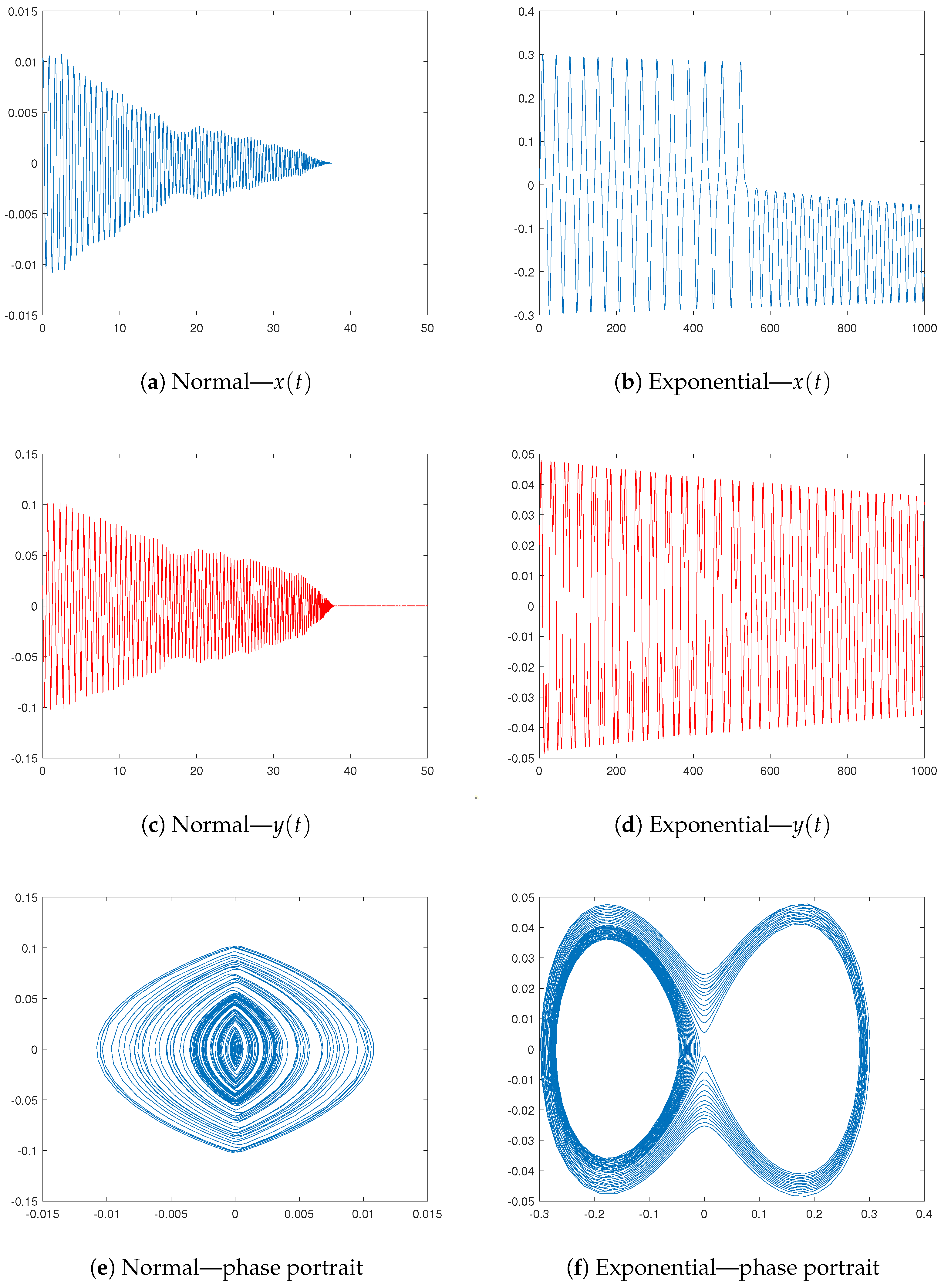
We shall provide two particular cases based on two distributions—the normal and exponential ones. These distributions are widely used in many real-life fields where a stochastic element is necessary for describing different uncertainty phenomena. Their densities are
p n o r m = 1 2 π σ 2 e x μ 2 σ 2 p e x p = λ e λ x .
The parameters μ and σ for the normal distributions are the expectation and the standard deviation, whereas λ is the intensity of the exponential law. The domains at which the distributions are defined are R and R + , respectively. The related characteristic functions are
Ψ n o r m = e i μ x σ 2 x 2 2 Ψ e x p = λ λ i x .
Having in mind Formulas (12) and (16), we rewrite the y-dynamics in the Gaussian case as
d y d t = a x b x x α 1 + ϵ e σ 2 ω 2 t 2 2 cos μ ω t A y y p 1 ,
since
Ψ n o r m x + Ψ n o r m x = 2 e σ 2 x 2 2 cos μ x .
Let us consider how the model is affected by the parameters. There is not much of a generalization by the expectation because q plays a scaling role in the periodic function. But for σ , this is not the case. First, the effect of σ is greater for small time values. The exponent is close to one when σ is close to zero; hence, the model resembles the original version with a single periodic function. However, when σ goes to infinity, the exponent disappears, making the periodic function’s influence insignificant. The same results can be drawn for larger values of t, but for values of σ that are closer to zero (infinity)—the greater t, the more extreme values of σ are required to capture the desired behavior.
  • If we work with the exponential distribution, then
    Ψ x + Ψ x = 2 λ 2 λ 2 + x 2 .
    Thus, the y-dynamics turns into
    d y d t = a x b x x α 1 + ϵ λ 2 λ 2 + ω 2 t 2 A y y p 1 .
    It is evident that a damping term reciprocal to the square of the period is introduced into the model by the exponential distribution. One way to think of the intensity λ is as a scaling parameter—the larger λ , the larger t must be. This reliance is linear as well.
  • The behavior of both types of oscillators can be viewed in Figure 9. The used parameters for the Gaussian oscillator are a = 0.6 , b = 0.85 , ϵ = 0.001 , p = 1.2 , ω = 0.2 , A = 1.5 , μ = 1 , and σ = 1 . We change only the variable p to p = 0.2 for the exponential case. The intensity is assumed to be λ = 1 . The ODE systems are solved through the platform MATLAB2024a. There are several integrated solvers that use different numerical methods. The basic ones for non-stiff equations are ode23, ode45, ode78, ode89, and ode113—they are mainly based on the large Runge–Kutta family. On the other hand, stuff equations can be solved through ode15s, ode23s, ode23t, and ode23tb. Our choice falls on the ode45 that is based on the Dormand–Prince modification of the Runge–Kutta method—see [31]. The main reasons is that there is no evidence for a possible stiffness as well as its large applicability. Furthermore, some experiments based on the other solvers lead to non-significant differences in the behavior. For more details on the different numerical methods and their implementation in MATLAB, we refer to Chapter 7 of [32].
Having in mind relations (18) and (19), we rewrite Melnikov integral (14) as
M t 0 = y 0 t e σ 2 ω 2 t + t 0 2 2 cos μ ω t + t 0 A y 0 t y 0 t p 1 d t .
for the Gaussian oscillator and as
M t 0 = y 0 t λ 2 λ 2 + ω 2 t + t 0 2 A y 0 t y 0 t p 1 d t .
for the exponential one.

6. Application of Melnikov Polynomials for the Synthesis of Antenna Arrays

Let us now focus on M ( t ) . We define the hypothetical normalized antenna factor as follows:
M * ( θ ) = 1 D | M ( K cos θ + k 1 ) | ,
where the azimuth angle is denoted by θ , the wavelength by 2 π λ ; the distance between emitters by d; the phase difference by k 1 ; and the interval under consideration by D = max M ( θ ) .
Example 11.
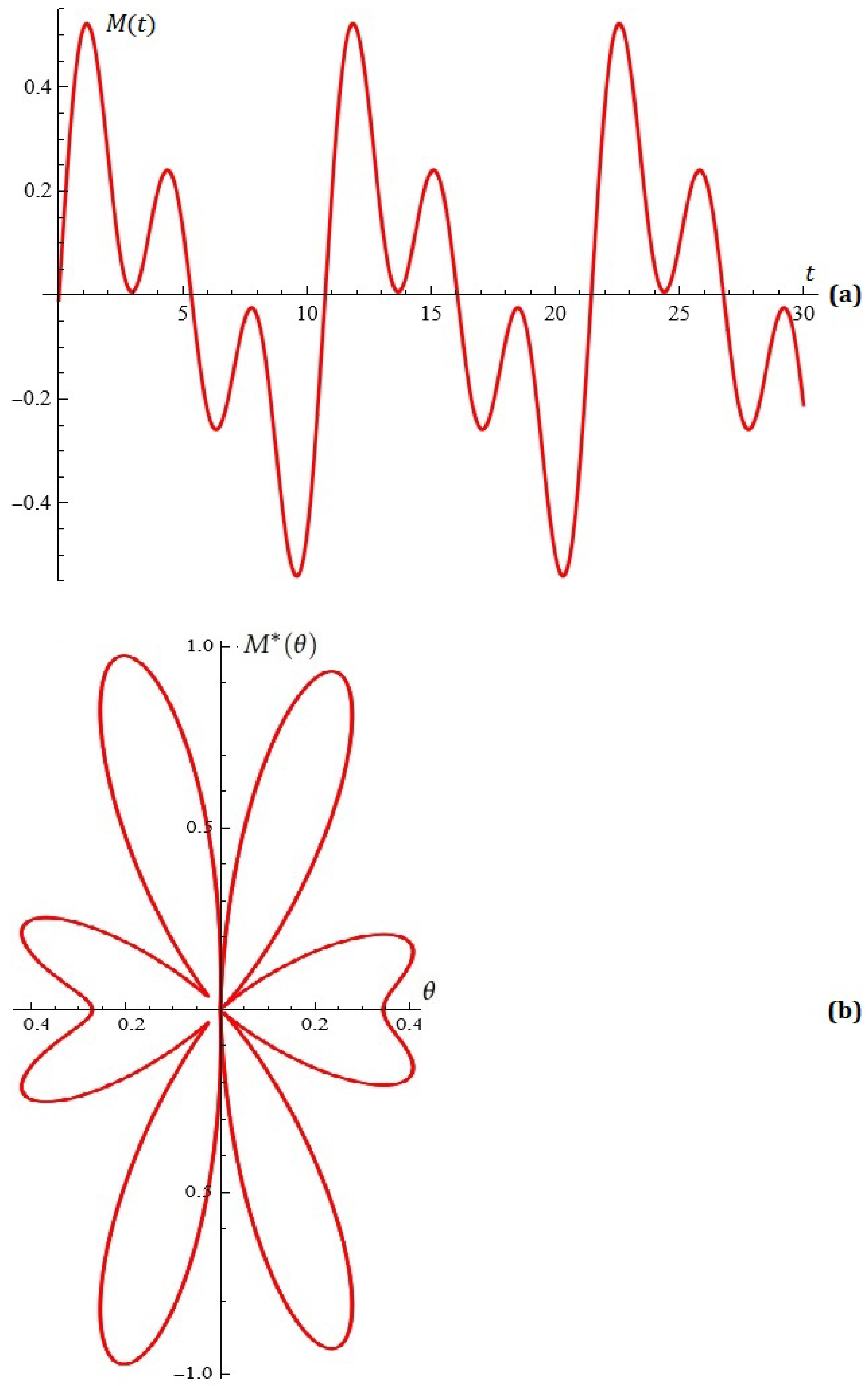
For fixed α = 6 ; p = 4 ; a = b = 1 ; N = 3 ; A = 0.02 ; ω = 0.586 ; a 1 = 0.2 ; a 2 = 0.1 ; a 3 = 0.2 ; k = 4.9 ; k 1 = 0.1  Figure 10 shows the normalized antenna factor M * ( θ ) and the equation M ( t 0 ) = 0 .
The equivalent approximation issue for arbitrarily selected α , damping exponent p, and N can be examined by the reader.
Since the output of the first module is used as the input for the second and most crucial module, which is intended to generate and visualize the corresponding diagrams of radiating antenna factor, the user does not need to have an explicit representation of Melnikov’s polynomials for the purposes of our research (thankfully).
We will use appropriate examples to demonstrate what has been discussed.
Proposition 4.
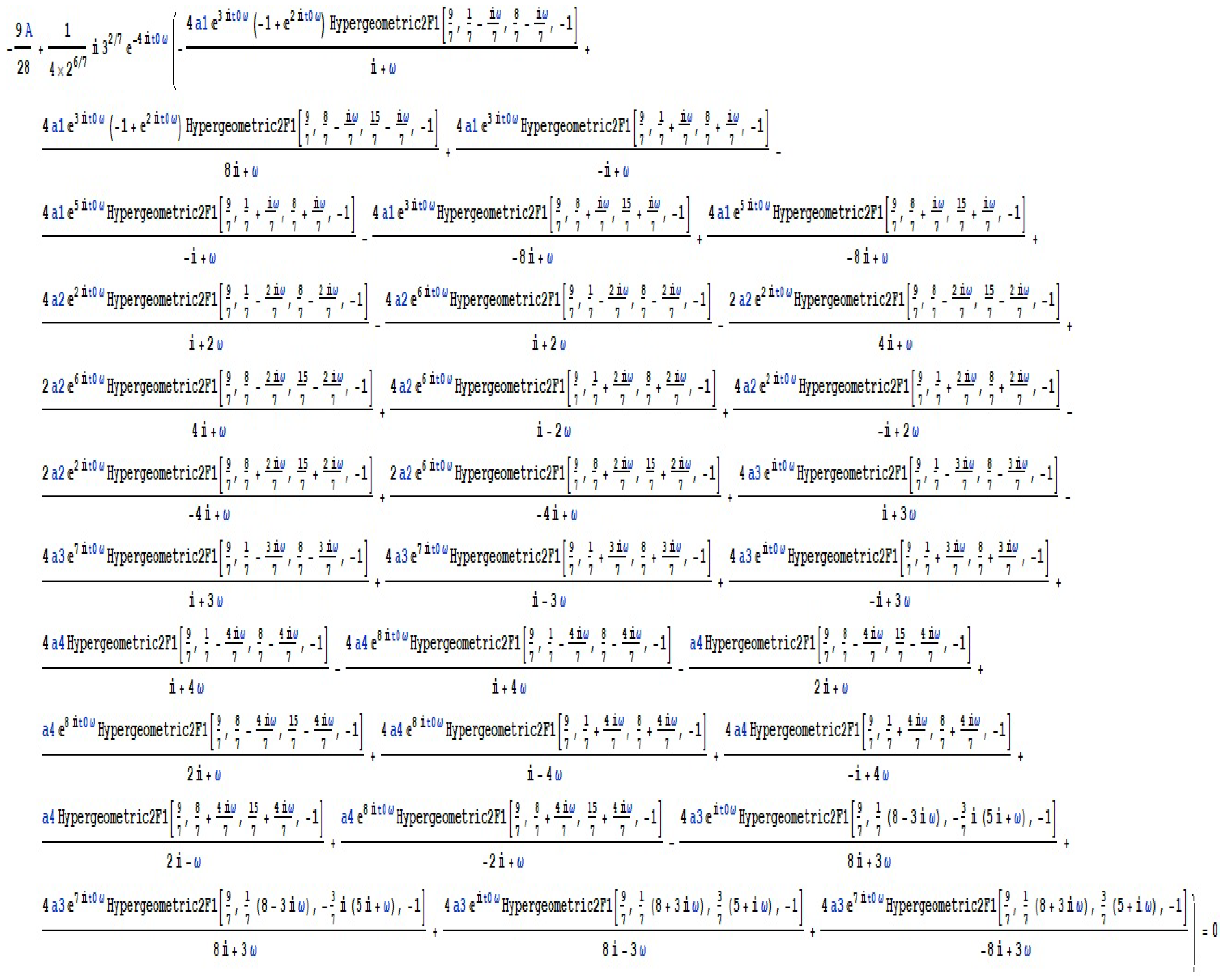
If α = 8 , p = 6 , N = 4 , a = b = 1 , and | Im ( ω ) | < 1 4 , then, as solutions to the equation in Figure A2, the roots of the Melnikov function M ( t 0 ) are provided.
Example 12.
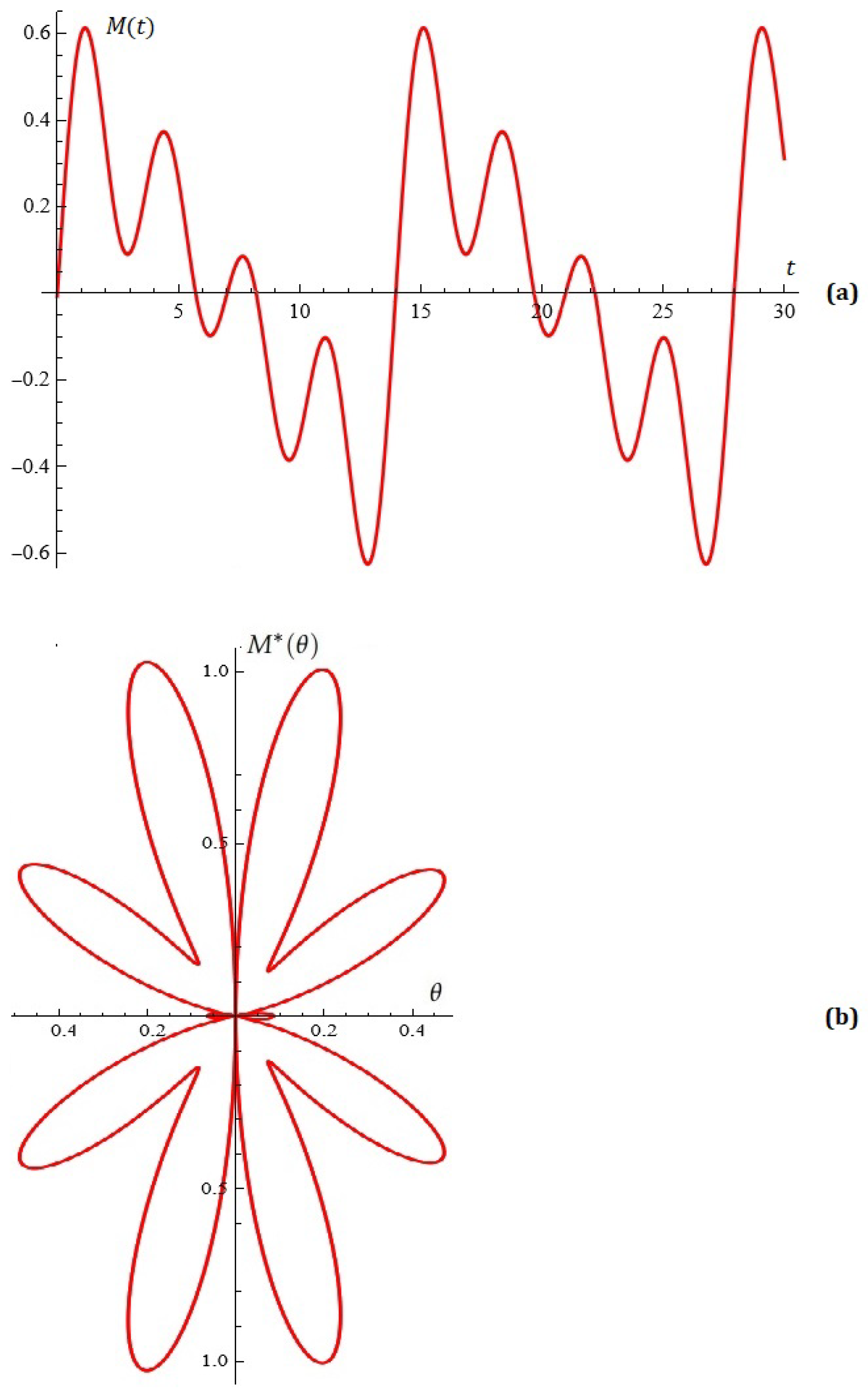
For fixed α = 8 ; p = 6 ; a = b = 1 ; N = 4 ; A = 0.02 ; ω = 0.45 ; a 1 = 0.3 ; a 2 = 0.1 ; a 3 = 0.1 ; a 4 = 0 , 2 ; k = 5.9 ; k 1 = 0 , Figure 11 shows the normalized antenna factor M * ( θ ) and the equation M ( t 0 ) = 0 .

Application of Melnikov Polynomials for Approximation of Impulse Functions and Point Sets in the Plane

The topic of noise minimization by the suitable approximation of impulse functions is a classic problem that has been studied by a number of authors and renowned specialists working in the field of approximation theory, operations research, and the synthesis and analysis of antennas and filters
Let K be the set of all plane points of the intervals [ a , a ] and [ i b , i b ] , where i 2 = 1 . The set K is called “CROSS”.
The problem for approximation of the point set ”CROSS” by algebraic polynomials P n ( x ) of degree n (n is an odd number) about uniform metric is solved by Akhiezer [33,34].
For other results, see [35].
For the solution of the above problem about the Hausdorff metric [36,37,38,39], see [40,41].
When designing antenna patterns with differential emission charts, these polynomials are crucial [42].
Problem. For fixed values of the parameters of our differential model α , p, N, let us generate the Melnikov function that well approximates the point set CROSS.
It is known [42,43] that the directivity diagram is composed of a main sheet and side sheets. The main sheet covers the sector containing the main radiation. At the ends of the sector, the field becomes equal to zero and sectors of side radiation (reception) begin, which are called side sheets of the antenna. The side sheet, which is in the opposite direction to the main sheet (at 180°) is called the back sheet.
Let us pay attention to the problem for decreasing the influence of the first biggest lobe after the basic one is the important problem. It is connected with “antenna noise” minimization.
This can be achieved, for example, by choosing side emissions envelopes.
Without community restriction, let us fix α = 10 , p = 8 , N = 6 .
Note. The parameter N is closely related to the number of emitters in the antenna array.
In the context of the above, it becomes clear that the solution of the above problem is closely related to the application of approximation and optimization techniques as follows.
Step 1. Generating the Melnikov function with fixed α , p, N, and free parameters—the remaining parameters of our differential model.
As a result of the implementation of this step, we can formulate the following conclusion
Proposition 5.
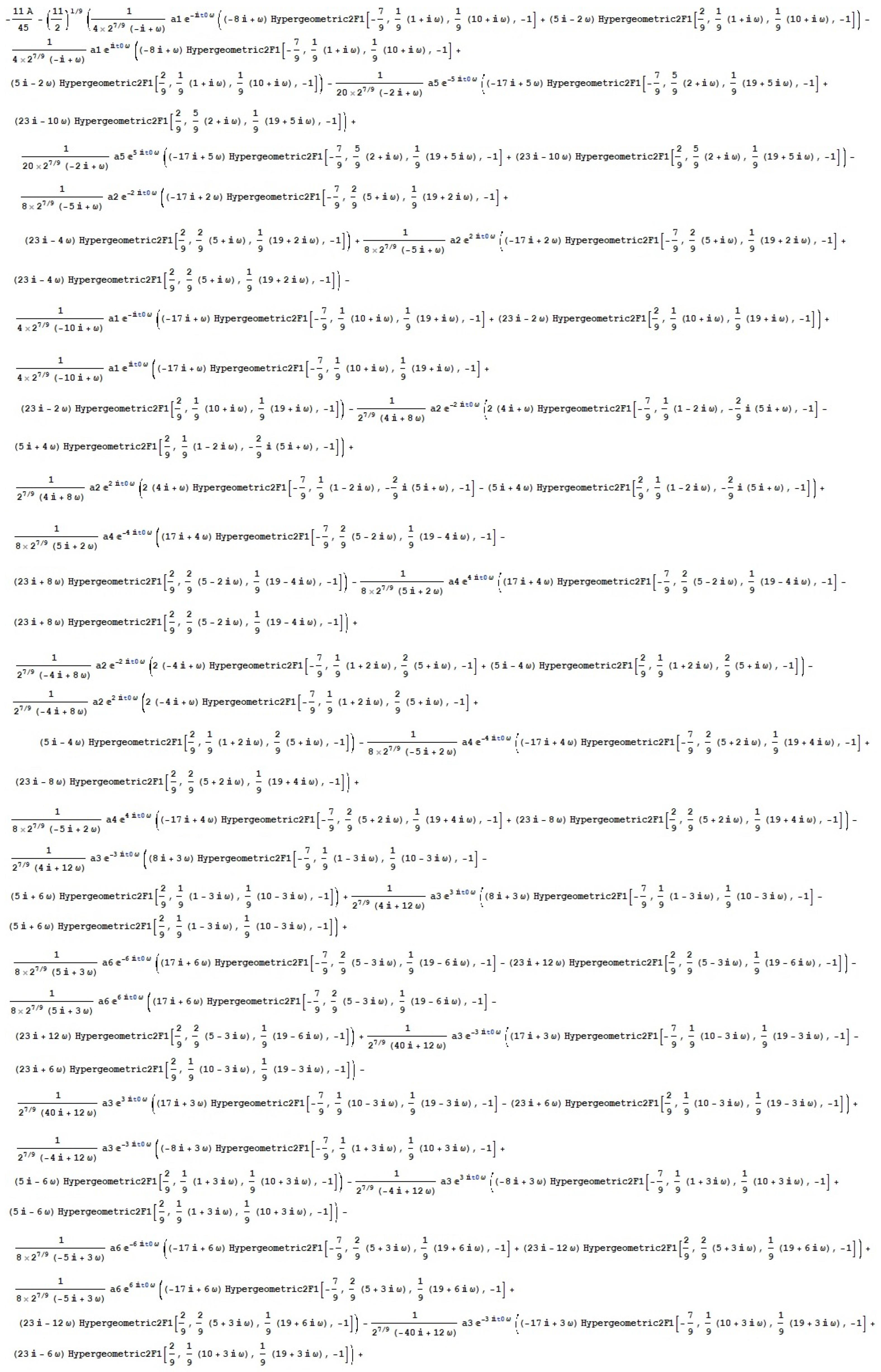
If α = 10 , p = 8 , N = 6 , a = b = 1 , and | I m ( ω ) | < 1 6 , then, as solutions to the equation in Figure A3, the roots of the Melnikov function M ( t 0 ) are provided.
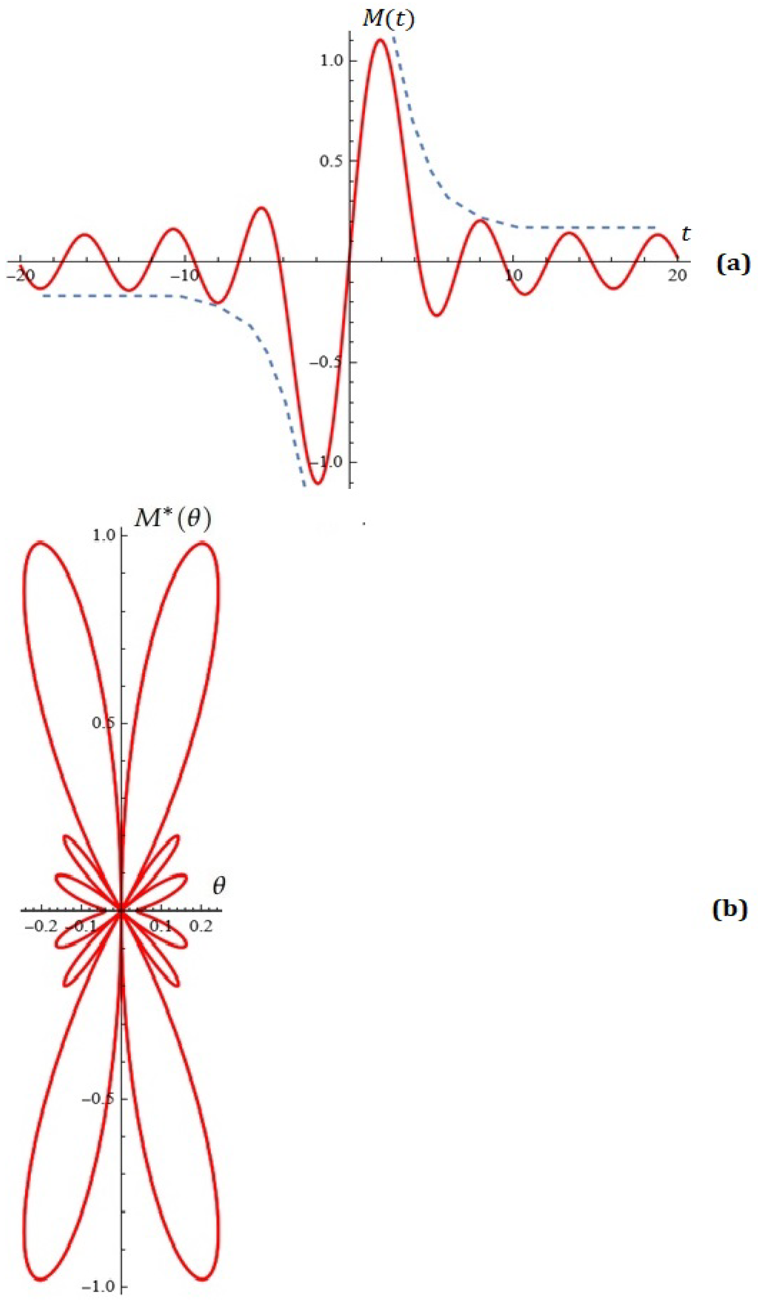
Step 2. A user-fixed envelope of the side leaves after the main extremum (see for example Figure 12a—dashed curve) is used to obtain the explicit form of M ( t ) , which well approximates the point set CROSS.
Without going into details, we will note that in the implementation of this step, we have essentially used the following classical algorithms:
-
a modified constructive algorithm from the field of approximation theory applied to the so-called ”approximations with constraints” (for more details, see [44,45,46,47,48,49,50,51,52]);
-
a modified optimization algorithm from the field of operation research (see, for example, [53,54]).
Our basic module implemented in CAS Mathematica practically offers a modified Remez algorithm for approximating functions and point sets in the plane with algebraic and trigonometric polynomials and polynomials of exponential type with respect to the uniform metric.
After applying the above algorithms, the M ( t ) obtained for the following parameters: A = 0.001 ; ω = 0.18 ; a 1 = a 2 = a 3 = a 4 = a 5 = a 6 = 0.2 is illustrated in Figure 12a.
The typical normalized Melnikov antenna factor (from (11)) for parameters k = 9.2 ; k 1 = 0 is depicted in Figure 12b.
From Figure 12, we are convinced that Melnikov’s polynomials play an important role for antenna pattern design with differential emitting charts.
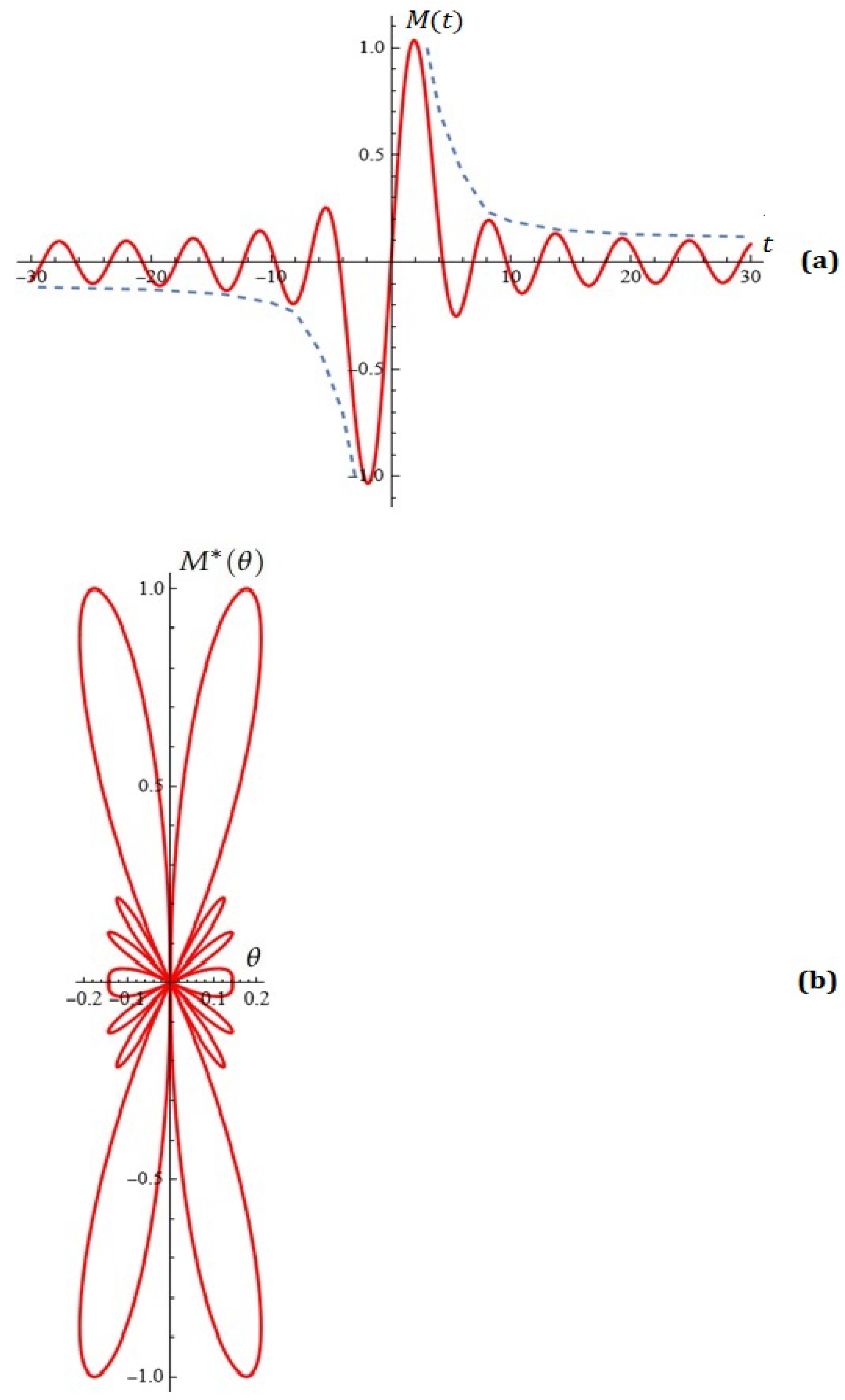
For completeness, we will consider another example of constructing M ( t ) following Step 1 approximating the point set CROSS at user-fixed values of the parameters of our differential model: N = 10 , α = 10 , p = 8 , a = b = 1 and the envelope of the lateral extrema (see Figure 13—dashed curve).
As a result of the implementation of the specialized module intended for this purpose included in the platform for scientific calculations planned by us (at this stage, intellectual property), we obtain the following illustration, which is placed in Figure 13.
The obtained parameters are A = 0.001 ; ω = 0.108 ; a 1 = 0.13 , a 2 = a 3 = a 4 = a 5 = a 6 = a 7 = a 8 = a 9 = 0.115 , a 10 = 0.13 .
The typical normalized Melnikov antenna factor (from (11)) for parameters: k = 10.972 , k 1 = 0 is depicted in Figure 13b.
The considered algorithms play an important role in the side emission level of the directed diagram of the antenna pattern.
Some notes. To determine A k coefficients, the standard N-element linear phased array factor is
A F ( θ ) = k = 1 N 2 A k cos ( ( 2 k 1 ) u ) = M ( x ) ,
where x = x 0 cos u , where x 0 is a design parameter, d is element spacing, θ is the polar angle, and u = π d λ cos θ .
The array geometry, amplitudes, and phase of the stimulation of individual antennas all affect the array factor.
Soltis [55] used this concept in his creation of novel Gegenbauer-like and Jacobi-like antenna arrays. For other results, see [56,57,58,59,60].
For large values of the parameter N, specialized numerical methods for solving large-scale systems should be used to calculate the coefficients A i (see, for example, [61,62].)
Methods for the synthesis of antenna grids with a level control of side emission, calculation of the normalized amplitudes of the excited currents of the emitters, and calculation of energetic characteristics can be found in the research of a number of authors.
The program codes of some type of antennas in programming environment MATLAB, as well as electronic calculators, are given in [63].
Statistical investigations and conclusions for big antenna systems are considered in [64], where additional sources of information are available. For other results, see [65].
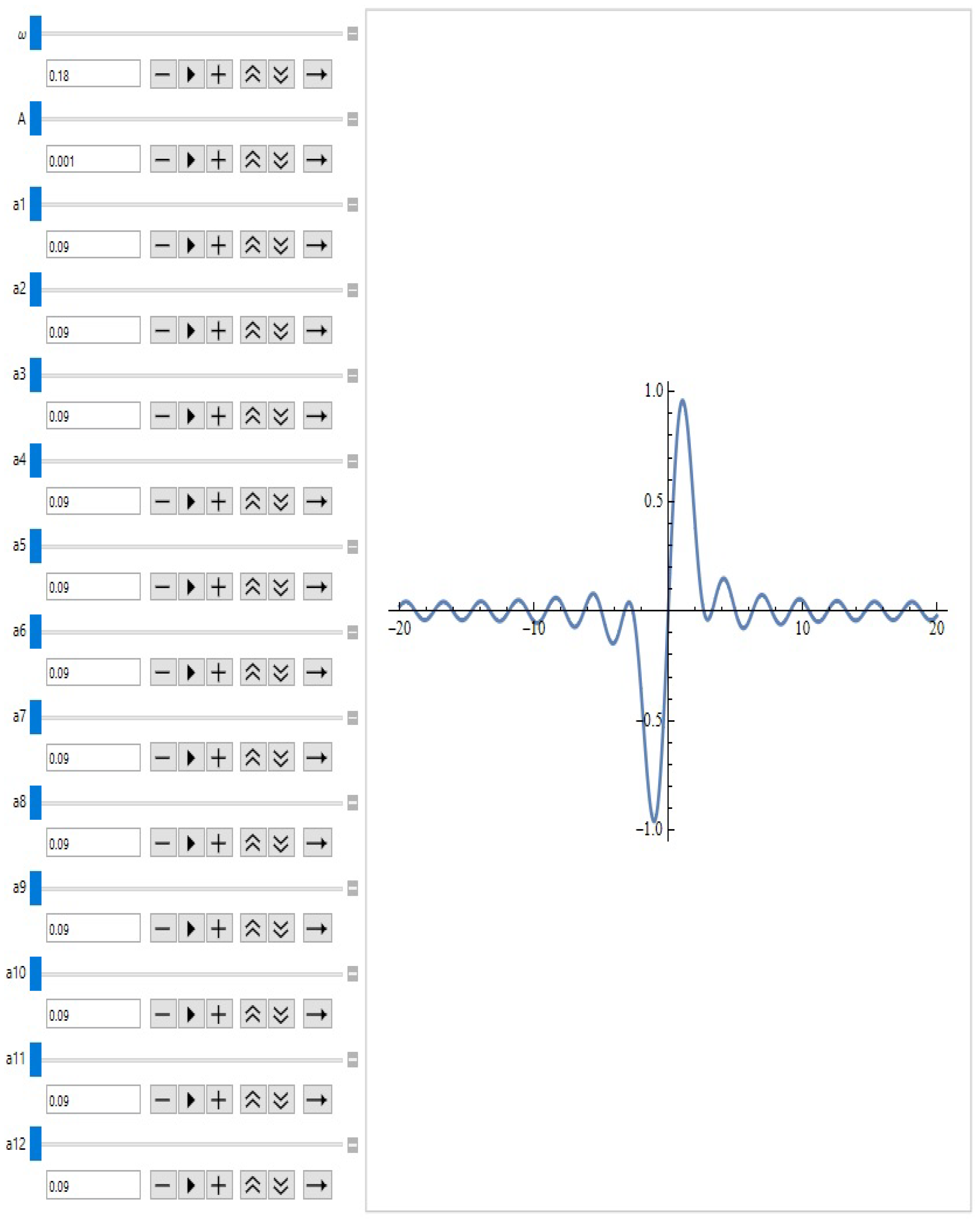
For large values of the parameter N, after calculating the integral (9) and applying the described approximation and optimization techniques, the Melnikov function approximating the point set K can be drawn in the CAS MATHEMATICA programming environment by the operator M a n i p u l a t e [ P l o t [ . . . ] ] (see, for example, Figure 14 for fixed N = 12 , α = 10 , p = 8 ).
The specified operator as well as the operator A n i m a t e [ P l o t [ . . . ] ] can be very useful to researchers in the analysis and visualization of antenna factors with specific restrictions imposed on them.

7. Concluding Remarks

In this research, we have examined a novel hypothetical differential model that has a large number of free parameters, which makes it appealing to users. We present a few specific modules for examining these oscillators’ behavior. This will be an essential component of a much broader Web-based program for scientific computing that is in the works.
A sufficient requirement for the perturbed system to have a transverse hetero-clinic cycle and, thus, to exhibit chaotic behavior in the sense of Smale is obtained by applying the well-known Melnikov’s approach.
The task of determining the roots of M ( t 0 ) = 0 is more intriguing from a numerical perspective, since the parameters that appear in the suggested differential model are subject to certain practical and physical constraints.Numerical methods for solving nonlinear equations can be found in [66,67,68,69,70].
The application that Melnikov functions may find to approximate impulse functions and exact sets in the plane is discussed. A possible application for generating antenna factors using approximation and optimization techniques is analyzed.
The aforementioned idea of Soltis [55], the innovative Gegenbauer-like and Jacobi-like antenna arrays he created, can be successfully extended to a new class of Melnikov-like antenna arrays. It is enough to apply the technique that Soltis used when comparing his proposed arrays with the classical Dolph–Chebyshev arrays. We foresee such an analysis in future developments on this interesting topic.
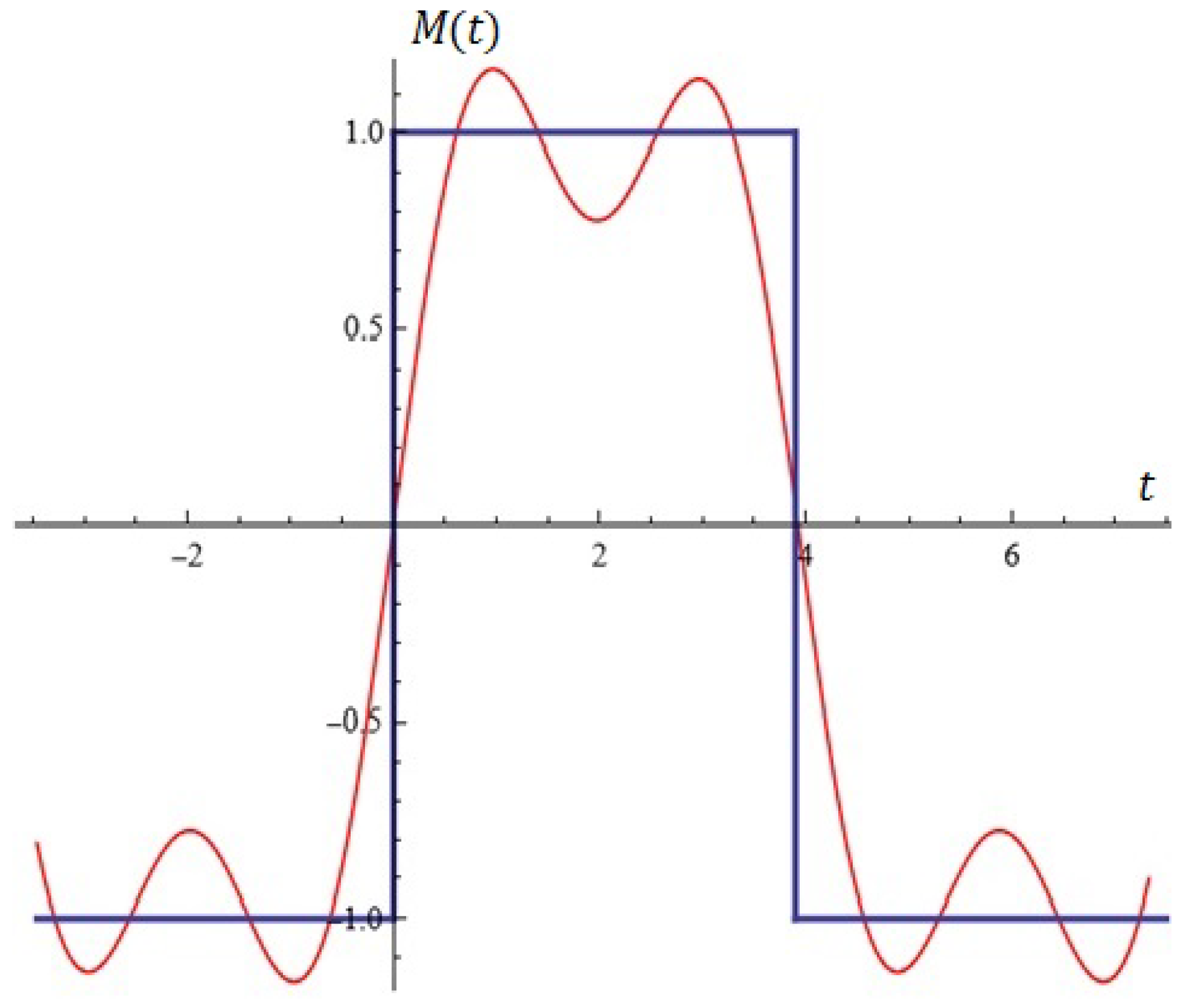
Some notes. Let us consider the problem for approximation of the impulse function (see Figure 15—in blue color) using M ( t ) .
In view of the specificity of this function, it is necessary to generate the Melnikov function from (9) for odd values of N = 3 , 5 , 7 ,
To illustrate what has been said, let us use the already generated function M ( t ) from Proposition 3 for fixed values N = 3 , p = 4 , α = 6 .
After applying the mandatory approximation and optimization techniques, the graph of M ( t ) is given in Figure 15 (in red color) for A = 0.0001 , ω = 0.8 , a 1 = 0.79 , a 2 = 0.01 , a 3 = 0.49 .
Obviously, M ( t ) can be used for the approximation and synthesis of electrical circuits.
It is well known that not every synthesized diagram is practically realizable [41,71]. In this regard, experts working in this field of study are seriously investigating this relatively novel concept of justification and right to exist.
We will consider another typical example related to the possible approximation of the impulse function (see Figure 16—in blue) by M ( t ) .
First of all, we will generate the function M ( t ) from (9) for N = 7 , p = 4 , α = 6 .
Using the described approximation techniques, the graph of M ( t ) is given in Figure 16 (in red color) for A = 0.0001 , ω = 0.75 , a 1 = 0.75 , a 2 = a 3 = = a 6 = 0.05 , a 7 = 0.75 .
Obviously, M ( t ) can be used for the approximation and synthesis of electrical stages.
We will explicitly note that questions related to the approximation of such electrical steps with rational functions regarding uniform and Hausdorff metrics can be found in the excellent monograph [72]. The proposed method is based on a modified Remez algorithm.
As we already mention in Section 5, simulations of the differential system were performed using the Dormand–Prince modification of the Runge–Kutta method. Also, we have used various computational tools: a numerical method for solving the extended mixed differential system; some specialized algorithms implemented in our Web application (at this stage intellectual property) for investigating the dynamics of the proposed new oscillators; a numerical algorithm for calculating the Melnikov integral under some assumptions given by the user (for non-specialists, we provide the possibility of automatic visualization of this function, its study and formulation of the mentioned criterion for the occurrence of chaos for large values of parameter N); numerical methods hidden from the user for an approximate solution of nonlinear equations (in some cases also numerical methods for simultaneously finding all zeros of exponential polynomials) have been used.
In Section 6, when discussing the possibility of application that Melnikov functions may find for the approximation of impulse functions and point sets in the plane as well as for the modeling and synthesis of antenna diagrams, we mentioned that well-known classical methods from the field of approximation theory and optimization theory, numerical methods for solving large systems of equations for determining the amplitudes of the excitation currents, etc. were used. The nature of this paper does not allow us to detail the listed procedures, which would require significant additional text that is unnecessary at this research stage in our opinion. In general, the issues raised in the above-cited section, especially the possibility of the practical implementation of a radiation diagram, can be considered open.
For all numerical methods and algorithms (approximation and optimization) used in this paper, an appropriate literature reference is provided.
We will explicitly note that in this article, we propose an effective approach to training with a specific focus on learning, provoking the thinking of our doctoral students through the triad enigmatics–creativity–acmeology. A large part of the examples given are actually study examples. The real task that we set for the students is the following: with fixed basic parameters of the considered differential model to generate an appropriate simulation of the model, with given user constraints (they can be of different nature: control of oscillations in confidential intervals; level of lateral emission of diagrams generated on the basis of Melnikov polynomials; magnitude of best approximation when it comes to approximating point sets in the plane, etc.). After using the specialized modules provided by us (with additional approximation and optimization algorithms included), implemented in CAS Mathematica, the students relatively easily reach the answer for each task, namely determining all other parameters of the model for which the above-mentioned constraints are satisfied. In particular, it is about making modern GPT technologies, which are massively used by students for the realization of their scientific tasks, as difficult as possible. We, the teachers, have a huge responsibility: on the one hand, we must encourage students of Master’s and doctoral programs to use modern technologies, and on the other hand, we encourage them to present the taught material at a level—”reading with comprehension”, which greatly limits the possibility of indiscriminate and "at any cost" use of these technologies.

Author Contributions

Conceptualization, N.K. and T.Z.; methodology, N.K. and T.Z.; software, T.Z., V.K., A.R. and A.I.; validation, V.K., T.Z., A.I. and N.K.; formal analysis, N.K., V.K. and T.Z.; investigation, T.Z., N.K., V.K., A.R. and A.I.; resources, A.R., A.I., V.K., T.Z. and N.K.; data curation, V.K., A.R., T.Z., A.I. and N.K.; writing—original draft preparation, V.K., N.K., A.R. and T.Z.; writing—review and editing, A.R., V.K. and A.I.; visualization, V.K., N.K., A.R. and T.Z.; supervision, T.Z., A.I. and N.K.; project administration, T.Z. and N.K.; funding acquisition, A.R., T.Z., A.I. and N.K. All authors have read and agreed to the published version of the manuscript.

Funding

The first, third, and fifth authors are supported by the European Union-NextGenerationEU, through the National Plan for Recovery and Resilience of the Republic of Bulgaria, project No BG-RRP-2.004-0001-C01. The second author was financed by the European Union-NextGenerationEU, through the National Recovery and Resilience Plan of the Republic of Bulgaria, project No BG-RRP-2.004-0008.

Data Availability Statement

Data are contained within the article.

Conflicts of Interest

The authors declare no conflicts of interest.

Appendix A

Figure A1. Generating equation M ( t 0 ) = 0 in CAS Mathematica (Proposition 3).
Symmetry 17 01144 g0a1
Figure A2. Generating equation M ( t 0 ) = 0 in CAS Mathematica (Proposition 4).
Symmetry 17 01144 g0a2
Figure A3. Generating equation M ( t 0 ) = 0 in CAS Mathematica (Proposition 5).
Symmetry 17 01144 g0a3aSymmetry 17 01144 g0a3b

References

  1. Sanjuan, M. The Effect of Nonlinear Damping on the Universal Oscillator. Int. J. Bifurcat. Chaos 1999, 9, 735–744. [Google Scholar] [CrossRef]
  2. Soliman, M.S.; Thompson, J.M.T. The Effect of Nonlinear Damping on the Steady State and Basin Bifurcation Patterns of a Nonlinear Mechanical Oscillator. Int. J. Bifurcat. Chaos 1992, 2, 81–91. [Google Scholar] [CrossRef]
  3. Fangnon, R.; Ainamon, C.; Monwanou, A.V.; Mowadinou, C.H.; Orou, J.B. Nonlinear Dynamics of the Quadratic Damping Helmholtz Oscillator. Complexity 2020, 2020, 8822534. [Google Scholar] [CrossRef]
  4. Bikdash, M.; Balachandran, B.; Nayfeh, A. Melnikov Analysis for a Ship with a General Roll-Damping Model. Nonlinear Dyn. 1994, 6, 191–214. [Google Scholar] [CrossRef]
  5. Ravindra, B.; Mallik, A.K. Stability Analysis of a Non-Linearly Clamped Duffing Oscillator. J. Sound Vib. 1999, 217, 708–716. [Google Scholar]
  6. Ravindra, B.; Mallik, A.K. Role of Nonlinear Dissipation in Soft Duffing Oscillators. Phys. Rev. E 1994, 49, 4950–4954. [Google Scholar] [CrossRef] [PubMed]
  7. Sanjuan, M. Monoclinic Bifurcation Sets of Driven Nonlinear Oscillators. Int. J. Theor. Phys. 1996, 35, 1745–1752. [Google Scholar] [CrossRef]
  8. Kyurkchiev, N.; Zaevski, T.; Iliev, A.; Kyurkchiev, V.; Rahnev, A. Modeling of Some Classes of Extended Oscillators: Simulations, Algorithms, Generating Chaos, and Open Problems. Algorithms 2024, 17, 121. [Google Scholar] [CrossRef]
  9. Kyurkchiev, N.; Zaevski, T.; Iliev, A.; Kyurkchiev, V.; Rahnev, A. Generating Chaos in Dynamical Systems: Applications, Symmetry Results, and Stimulating Examples. Symmetry 2024, 16, 938. [Google Scholar] [CrossRef]
  10. Kyurkchiev, N.; Zaevski, T.; Iliev, A.; Kyurkchiev, V.; Rahnev, A. Investigations of Modified Classical Dynamical Models: Melnikov’s Approach, Simulations and Applications, and Probabilistic Control of Perturbations. Mathematics 2025, 13, 231. [Google Scholar] [CrossRef]
  11. Tang, K.; Man, K.; Zhong, G.; Chen, G. Generating Chaos via x|x|. IEEE Trans. Circuits Syst. Fundam. Theory Appl. 2001, 48, 636–640. [Google Scholar] [CrossRef]
  12. Cveticanin, L.; Zukovic, M. Melnikov’s Criteria and Chaos in Systems with Fractional Order Deflection. J. Sound Vib. 2009, 326, 768–779. [Google Scholar] [CrossRef]
  13. Tsend, W.; Dugundji, J. Nonlinear Vibration of a Buckled Beam under Excitation. J. Appl. Math. 1971, 38, 467–476. [Google Scholar]
  14. Holmes, P.; Marsden, J. A Partial Differential Equation with Infinitely Many Periodic Orbits: Chaotic Oscillations of a Forced Beam. Arch. Ration. Mech. Anal. 1981, 76, 135–166. [Google Scholar] [CrossRef]
  15. Du, L.; Zhao, Y.; Lei, Y.; Hu, J.; Yue, X. Suppression of Chaos in a Generalized Duffing Oscillator with Fractional Order Deflection. Nonlinear Dyn. 2018, 92, 1921–1933. [Google Scholar] [CrossRef]
  16. Zhang, Y.; Li, J.; Zhu, S.; Zhao, H. Chaos Detection and Control of a Fractional Piecewise-Smooth System with Nonlinear Damping. Chin. J. Phys. 2024, 90, 885–900. [Google Scholar] [CrossRef]
  17. Kyurkchiev, N.; Iliev, A.; Kyurkchiev, V.; Rahnev, A. One More Thing on the Subject: Generating Chaos via x|x|a-1, Melnikov’s Approach Using Simulations. Mathematics 2025, 12, 232. [Google Scholar] [CrossRef]
  18. Li, H.; Liao, X.; Huang, J.; Chen, G.; Dong, Z.; Huang, T. Diverting Homoclinic Chaos in a Class of Piecewise Smooth Oscillators to Stable Periodic Orbits Using Small Parametrical Perturbations. Neurocomputing 2015, 149, 1587–1595. [Google Scholar] [CrossRef]
  19. He, X.; Li, C.D.; Shu, Y.L. Bogdanov–Takens Bifurcation in a Single Inertial Neuron Model with Delay. Neurocomputing 2012, 89, 193–201. [Google Scholar] [CrossRef]
  20. Li, C.G.; Chen, G.R. Coexisting Chaotic Attractors in a Single Neuron Model with Adapting Feedback Synapse. Chaos Solitons Fractals 2005, 23, 1599–1604. [Google Scholar] [CrossRef]
  21. Dong, T.; Liao, X.F.; Huang, T.W.; Li, H.Q. Hopf–Pitchfork Bifurcation in an Inertial Two-Neuron System with Time Delay. Neurocomputing 2012, 97, 223–232. [Google Scholar] [CrossRef]
  22. Li, C.; Sun, J.; Lu, T.; Lei, T. Symmetry Evolution in Chaotic System. Symmetry 2020, 12, 574. [Google Scholar] [CrossRef]
  23. Li, C.; Li, Z.; Jiang, Y.; Lei, T.; Wang, X. Symmetric Strange Attractors: A Review of Symmetry and Conditional Symmetry. Symmetry 2023, 15, 1564. [Google Scholar] [CrossRef]
  24. Melnikov, V.K. On the Stability of a Center for Time-Periodic Perturbation. Trans. Mosc. Math. Soc. 1963, 12, 3–52. [Google Scholar]
  25. Golev, A.; Terzieva, T.; Iliev, A.; Rahnev, A.; Kyurkchiev, N. Simulation on a Generalized Oscillator Model: Web-Based Application. C. R. Acad. Bulg. Sci. 2024, 77, 230–237. [Google Scholar] [CrossRef]
  26. Hutu, F.; Cauet, S.; Coirault, P. Antenna Arrays Principle and Solutions: Robust Control Approach. Int. J. Comput. Commun. Control 2008, 3, 161–171. [Google Scholar] [CrossRef][Green Version]
  27. Hutu, F.; Cauet, S.; Coirault, P. Robust Synchronization of Different Coupled Oscillators: Application to Antenna Arrays. J. Frankl. Inst. 2009, 346, 413–430. [Google Scholar] [CrossRef]
  28. Heath, T.; Kerr, R.R.; Hopkins, G.D. Two-Dimensional, Nonlinear Oscillator Array Antenna. In Proceedings of the 2005 IEEE Aerospace Conference, Big Sky, MT, USA, 5–12 March 2005; pp. 1104–1115. [Google Scholar]
  29. Iordache, M.; Paillot, J.M.; Dumitrescu, I.; Ionita, M. Analysis of Coupled Oscillators Applied to Antenna Arrays. Ann. Univ. Craiova Electr. Eng. Ser. 2010, 34, 1–10. [Google Scholar]
  30. Cheng, D.K. Optimization Techniques for Antenna Arrays. Proc. IEEE 2005, 59, 1664–1674. [Google Scholar] [CrossRef]
  31. Dormand, J.R.; Prince, P.J. A family of embedded Runge-Kutta formulae. J. Comput. Appl. Math. 1980, 19–26. [Google Scholar] [CrossRef]
  32. Moler, C.B. Numerical Computing with MATLAB; Society for Industrial and Applied Mathematics: Philadelphia, PA, USA, 2004. [Google Scholar]
  33. Akhiezer, N.I. Elements of the Theory of Elliptic Functions; Nauka: Moscow, Russia, 1970. [Google Scholar]
  34. Akhiezer, N.I. Theory of Approximation; Nauka: Moscow, Russia, 1965. [Google Scholar]
  35. Voronovskaya, E. Odd Polynomials of Least Deviation. Dokl. Akad. Nauk SSSR 1964, 159, 715–718. [Google Scholar]
  36. Sendov, B. Hausdorff Distance and Image Processing. Usp. Mat. Nauk 2004, 59, 127–136. [Google Scholar] [CrossRef]
  37. Sendov, B.; Popov, V. The Exact Asymptotic Behavior of the Best Approximation by Algebraic and Trigonometric Polynomials in the Hausdorff Metric. Math. Ussr-Sb. 1972, 89, 138–147. [Google Scholar] [CrossRef]
  38. Andreev, A. A Numerical Method for Finding the Polynomial of Best Hausdorff Approximation. Dokl. Bolg. Akad. Nauk. 1976, 29, 163–166. [Google Scholar]
  39. Bochev, V.; Marinov, P.; Nushev, P.; Cecchin, T. An FPGA/PLSI Hausdorff Distance Processor Design for Pattern Recognition Applications. In Proceedings of the International Conference on Signal Processing Applications and Technology, Detroit, MI, USA, 8–12 May 1995; pp. 1015–1018. [Google Scholar]
  40. Kyurkchiev, N.; Markov, S. On the Numerical Approximation of the Point Set “Cross”. Ann. Univ. Sofia Fac. Math. 1972, 66, 19–25. [Google Scholar]
  41. Kyurkchiev, N. Synthesis of Slot Aerial Grids with Hausdorff Type Directive Patterns. Ph.D. Thesis, VMEI, Sofia, Bulgaria, 1979. [Google Scholar]
  42. Minkovich, V.; Yakovlev, V.P. Theory of Antenna Synthesis; Sovetskoe Radio: Moscow, Russia, 1969. [Google Scholar]
  43. Dolph, C.L. A Current Distribution for Broadside Arrays which Optimizes the Relationship between Beam Width and Side-Lobe Level. Proc. IRE 1946, 34, 335–348. [Google Scholar] [CrossRef]
  44. Remez, E.Y. General Computational Methods of Chebyshev Approximation. The Problem with Linear and Real Parameters; United States Atomic Energy Commission: Washington, DC, USA, 1962. [Google Scholar]
  45. Remez, E.Y. Fundamentals of Numerical Methods for Chebyshev Approximation; Naukova Dumka: Kiev, Ukraine, 1969. [Google Scholar]
  46. Meinardus, G. Approximation of Functions: Theory and Numerical Methods; Springer: New York, NY, USA, 1967. [Google Scholar]
  47. Natanson, I.P. Constructive Function Theory. Vol. I: Uniform Approximation; Frederick Ungar Publishing Co.: New York, NY, USA, 1964. [Google Scholar]
  48. Natanson, I.P. Constructive Function Theory. Vol. II: Approximation in Mean; Frederick Ungar Publishing Co.: New York, NY, USA, 1965. [Google Scholar]
  49. Natanson, I.P. Constructive Function Theory. Vol. III: Interpolation and Approximation Quadratures; Frederick Ungar Publishing Co.: New York, NY, USA, 1965. [Google Scholar]
  50. Tashev, S. Hausdorff Approximation and Differential Equations with Multivalued Right Part. Ph.D. Thesis, Sofia University, Sofia, Bulgaria, 1978. [Google Scholar]
  51. Tashev, S. Some Converse Theorems in Hausdorff Metric. In Proceedings of the International Conference on Constructive Function Theory, Blagoevgrad, Bulgaria, 30 May–6 June 1977; pp. 145–149. [Google Scholar]
  52. Tashev, S. Approximation of Bounded Sets on the Plane in Hausdorff Metric. C. R. Acad. Bulg. Sci. 1976, 29, 465–468. [Google Scholar]
  53. Tu, L.; Ng, B.P. Exponential and Generalized Dolph–Chebyshev Functions for Flat-Top Array Beam Pattern Synthesis. Multidimens. Syst. Signal Process. 2013, 24, 1–12. [Google Scholar]
  54. Yang, X.; Teo, K.L.; Caccetta, L. (Eds.) Optimization Methods and Applications; Springer: New York, NY, USA, 2001. [Google Scholar]
  55. Soltis, J.J. New Gegenbauer-like and Jacobi-like Polynomials with Applications. J. Frankl. Inst. 1993, 330, 635–639. [Google Scholar] [CrossRef]
  56. Malinova, A.; Kyurkchiev, V.; Iliev, A.; Rahnev, A.; Kyurkchiev, N. The Gegenbauer-like and Jacobi-like Polynomials: An Overview in the Light of Soltis Considerations, Some Applications. Int. Electron. J. Pure Appl. Math. 2023, 17, 23–41. [Google Scholar]
  57. Kyurkchiev, N.; Andreev, A. Synthesis of Slot Aerial Grids with Hausdorff-Type Directive Patterns—Implementation in Programming Environment Mathematica. C. R. Acad. Bulg. Sci. 2013, 66, 1521–1528. [Google Scholar]
  58. Apostolov, P. An Addition to Binomial Array Antenna Theory. Prog. Electromagn. Res. Lett. 2023, 113, 113–117. [Google Scholar] [CrossRef]
  59. Apostolov, P.S. Linear Equidistant Antenna Array with Improved Selectivity. IEEE Trans. Antennas Propag. 2011, 59, 3940–3943. [Google Scholar] [CrossRef]
  60. Gachev, M. Synthesis of Antenna Grids with Optimal Directivity Chart. Ph.D. Thesis, VMEI, Sofia, Bulgaria, 1981. [Google Scholar]
  61. Gould, N.; Orban, D.; Toint, P. Numerical Methods for Large-Scale Nonlinear Optimization. Acta Numer. 2005, 14, 299–361. [Google Scholar] [CrossRef]
  62. Fletcher, R. Practical Methods of Optimization: Constrained Optimization; Wiley: Chichester, UK, 1981. [Google Scholar]
  63. Joseph, S.K.; Schoebel, J. Designing Antenna Arrays Using Signal Processing, Image Processing and Optimization Toolboxes of MATLAB. In MATLAB-Modelling, Programming and Simulations; Leite, E.P., Ed.; InTech: Rijeka, Croatia, 2010; pp. 1–20. [Google Scholar]
  64. Vinogradova, J.; Couillet, R.; Hachem, W. Statistical Inference in Large Antenna Arrays under Unknown Noise Pattern. arXiv 2013, arXiv:1301.0306. [Google Scholar] [CrossRef]
  65. Fiks, G.E.; Fiks, I.S. Optimal Statistical Antenna Synthesis Using the Near-Zone Field. Radiophys. Quantum Electron. 2009, 52, 1–10. [Google Scholar] [CrossRef]
  66. Ullah, M.; Behl, R.; Argyros, I. Some High-Order Iterative Methods for Nonlinear Models Originating from Real Life Problems. Mathematics 2020, 8, 1249. [Google Scholar] [CrossRef]
  67. Argyros, I.K.; Sharma, D.; Argyros, C.I.; Parhi, S.K.; Sunanda, S.K. A Family of Fifth and Sixth Convergence Order Methods for Nonlinear Models. Symmetry 2021, 13, 715. [Google Scholar] [CrossRef]
  68. Kumar, S.; Bhagwan, J.; Jäntschi, L. Optimal Derivative-Free One-Point Algorithms for Computing Multiple Zeros of Nonlinear Equations. Symmetry 2022, 14, 1881. [Google Scholar] [CrossRef]
  69. Shams, M.; Kausar, N.; Araci, S.; Oros, G.I. Artificial Hybrid Neural Network-Based Simultaneous Scheme for Solving Nonlinear Equations: Applications in Engineering. Alex. Eng. J. 2024, 108, 292–305. [Google Scholar] [CrossRef]
  70. Liu, T.; Xue, R. A Convergent Multi-Step Efficient Iteration Method to Solve Nonlinear Equation Systems. J. Appl. Math. Comput. 2024, 2, 2571–2588. [Google Scholar] [CrossRef]
  71. Shinev, H.; Tashev, S.; Kyurkchiev, N. A Method for Synthesis of Antenna Grids with Level Control of Side Emission. In Proceedings of the Scientific-Technical International Conference “Radiolocation and Radiorelay Lines”, Varna, Bulgaria, 17–18 October 1980. [Google Scholar]
  72. Sendov, B.; Andreev, A. Approximation and Interpolation Theory. In Handbook of Numerical Analysis; Ciarlet, P., Lions, J., Eds.; Elsevier Science Publisher: Amsterdam, The Netherlands, 1994; Volume III, pp. 223–462. [Google Scholar]
Figure 1. (a) The equation M ( t 0 ) = 0 (Example 1); (b) the equation M ( t 0 ) = 0 (Example 2).
Symmetry 17 01144 g001
Figure 2. Generating equation M ( t 0 ) = 0 utilizing Proposition 2 in CAS Mathematica.
Symmetry 17 01144 g002
Figure 3. (a) The equation M ( t 0 ) = 0 (Example 3); (b) the equation M ( t 0 ) = 0 (Example 3).
Symmetry 17 01144 g003
Figure 4. (a) The equation M ( t 0 ) = 0 (Example 4); (b) the equation M ( t 0 ) = 0 (Example 5).
Symmetry 17 01144 g004
Figure 5. (a) The solutions of the system; (b) phase space (example 6).
Symmetry 17 01144 g005
Figure 6. (a) The solutions of the system; (b) phase space (example 7).
Symmetry 17 01144 g006
Figure 7. (a) The solutions of the system; (b) phase space (example 8).
Symmetry 17 01144 g007
Figure 8. (a) The solutions of the system; (b) phase space (example 9).
Symmetry 17 01144 g008
Figure 9. The first column is for the model with the Gaussian CDF, whereas the second one is for the exponential. In the first row, we present the x-dynamics, the second one is for the y-dynamics, and the third one is for the phase portrait.
Symmetry 17 01144 g009
Figure 10. (a) The equation M ( t 0 ) = 0 ; (b) a typical Melnikov antenna factor (from Example 11).
Symmetry 17 01144 g010
Figure 11. (a) The equation M ( t 0 ) = 0 ; (b) a typical Melnikov antenna factor (from Example 12).
Symmetry 17 01144 g011
Figure 12. (a) Melnikov function M ( t ) by user-fixed envelope of the side leaves; (b) a typical Melnikov antenna factor.
Symmetry 17 01144 g012
Figure 13. (a) Melnikov function M ( t ) by user-fixed envelope of the side leaves; (b) a typical Melnikov antenna factor.
Symmetry 17 01144 g013
Figure 14. M a n i p u l a t e [ P l o t [ . . . ] ] for fixed N = 12 , α = 10 , p = 8 .
Symmetry 17 01144 g014
Figure 15. Approximation of impulse function using M ( t ) for N = 3 , p = 4 , α = 6 , A = 0.0001 , ω = 0.8 , a 1 = 0.79 , a 2 = 0.01 , a 3 = 0.49 .
Symmetry 17 01144 g015
Figure 16. Approximation of impulse function using M ( t ) for N = 7 , p = 4 , α = 6 , A = 0.0001 , ω = 0.75 , a 1 = 0.75 , a 2 = a 3 = a 6 = 9.05 , a 7 = 0.75 .
Symmetry 17 01144 g016
Disclaimer/Publisher’s Note: The statements, opinions and data contained in all publications are solely those of the individual author(s) and contributor(s) and not of MDPI and/or the editor(s). MDPI and/or the editor(s) disclaim responsibility for any injury to people or property resulting from any ideas, methods, instructions or products referred to in the content.