Article

A Symmetry-Driven Broadband Circularly Polarized Magnetoelectric Dipole Antenna with Bandpass Filtering Response

School of Electronic Engineering and Intelligence, Dongguan University of Technology, Dongguan 523808, China
*
Author to whom correspondence should be addressed.
Symmetry 2025, 17(7), 1145; https://doi.org/10.3390/sym17071145 (registering DOI)
Submission received: 18 June 2025 / Revised: 8 July 2025 / Accepted: 15 July 2025 / Published: 17 July 2025
(This article belongs to the Special Issue Symmetry Study in Electromagnetism: Topics and Advances)

Abstract

This paper presents a symmetry-driven broadband circularly polarized magnetoelectric dipole antenna with bandpass filtering response, where the principle of symmetry is strategically employed to enhance both radiation and filtering performance. The antenna’s circular polarization is achieved through a symmetrical arrangement of two orthogonally placed metallic ME dipoles combined with a phase delay line, creating balanced current distributions for optimal CP characteristics. The design further incorporates symmetrical parasitic elements—a pair of identical inverted L-shaped metallic structures placed perpendicular to the ground plane at −45° relative to the ME dipoles—which introduce an additional CP resonance through their mirror-symmetric configuration, thereby significantly broadening the axial ratio bandwidth. The filtering functionality is realized through a combination of symmetrical modifications: grid slots etched in the metallic ground plane and an open-circuited stub loaded on the microstrip feed line work in tandem to create two radiation nulls in the upper stopband, while the inherent symmetrical properties of the ME dipoles naturally produce a radiation null in the lower stopband. This comprehensive symmetry-based approach results in a well-balanced bandpass filtering response across a wide operating bandwidth. Experimental validation through prototype measurement confirms the effectiveness of the symmetric design with compact dimensions of 0.96 λ 0 × 0.55 λ 0 × 0.17 λ 0 ( λ 0 is the wavelength at the lowest operating frequency), demonstrating an impedance bandwidth of 66.4% (2.87–5.05 GHz), an AR bandwidth of 31.9% (3.32–4.58 GHz), an average passband gain of 5.5 dBi, and out-of-band suppression levels of 11.5 dB and 26.8 dB at the lower and upper stopbands, respectively, along with good filtering performance characterized by a gain-suppression index (GSI) of 0.93 and radiation skirt index (RSI) of 0.58. The proposed antenna is suitable for satellite communication terminals requiring wide AR bandwidth and strong interference rejection in L/S-bands.

1. Introduction

For both transmitters and receivers, CP antennas offer superior signal transmission and reception sensitivity compared to linearly polarized antennas. They eliminate the need for polarization alignment and mitigate issues such as polarization mismatch, multipath effects, and channel crosstalk during signal propagation, thus reducing losses caused by polarization mismatch. These advantages make CP antennas widely applicable in various systems, including capsule endoscopy systems, satellites, radio frequency identification (RFID) systems, and wireless local area networks (WLANs) [1].
In the RF front-end, the antenna and the filter are two critical components. In conventional designs, they are designed separately and then cascaded, which inevitably introduces insertion loss. Consequently, the integrated design of antennas and filters, resulting in filtering antennas possessing both radiation characteristics and filtering functionality, has become a major research direction. Therefore, filtering antennas with CP characteristics hold significant importance and offer broad application prospects [2,3], making them a current research focus.
Among various approaches to developing high-performance CP filter antennas, the most direct and common method uses a filter with a 90° phase shift capability as the CP feeding network [4,5,6,7,8,9,10,11,12]. Metasurfaces have been used to achieve CP filtering in [13,14], while Ref. [15] combined a CP polarizer with a linearly polarized filtering antenna. However, both methods tend to increase antenna size and structural complexity. Microstrip patch antennas, being easy to integrate and structurally simple, are often the preferred choice for designing CP filtering antennas. Techniques such as introducing parasitic elements, etching slots, loading shorting elements on the CP patch antenna, or loading open-circuited stubs on the feed line can introduce radiation nulls on both sides of the antenna’s passband, achieving good bandpass filtering characteristics. For example, Ref. [16] introduced parasitic elements to generate opposing currents with the main radiating patch at specific frequencies to achieve filtering performance. Refs. [17,18] created slots on the metallic patch to induce current cancellation, thereby introducing radiation nulls. Ref. [19] achieves radiation nulls by introducing symmetrical rectangular parasitic elements on both sides of the main radiating patch and microstrip feed line, where proper coupling induces out-of-phase currents between the parasitic elements and the main patch; however, this method does not contribute to broadening the antenna’s circular polarization (CP) bandwidth. In [20], symmetrical slots etched on the ground plane are excited by the microstrip feed line to generate one CP operating frequency along with a radiation null. Since the slots are excited to facilitate CP generation, the back lobe radiation at this CP frequency becomes relatively large, necessitating an additional large reflective ground plane, which increases the antenna’s profile height. Ref. [21] realized good bandpass filtering characteristics by loading shorting patches and open-circuited stubs at the radiating slots. Ref. [22] implemented CP filtering performance by loading open-circuited stubs on the microstrip feed line. Beyond these methods, Ref. [23] used capacitive coupling between two orthogonally placed resonators to achieve second-order bandpass filtering. However, although these circularly polarized filtering patch antennas achieve bandpass filtering performance, they generally exhibit relatively narrow axial ratio bandwidths. Ref. [24] shifts the CP operating frequency toward the lower band by introducing counterclockwise-oriented metal strips on the left side of the four arms of a crossed dipole, yet this approach does not enhance the CP operating bandwidth. In contrast, the proposed antenna broadens the CP bandwidth by incorporating symmetrical parasitic elements beneath the magnetoelectric dipole arms to introduce an additional CP operating frequency. Moreover, the grid slots etched on the ground plane are solely utilized to generate radiation nulls and couple energy to the magnetoelectric dipole without being directly excited, thereby avoiding significant back lobe radiation.
This paper presents an antenna utilizing two orthogonally placed metallic ME dipoles and a phase delay line to achieve CP radiation characteristics. An inverted L-shaped metallic parasitic element is introduced to create an additional CP operating frequency, thereby expanding the antenna’s CP bandwidth. Leveraging the inherent characteristics of the crossed ME dipoles, a radiation null is naturally introduced in the lower stopband. Subsequently, etching grid slots in the metallic ground plane introduces a radiation null in the upper stopband. To further enhance the suppression level in the upper stopband, a pair of open-circuited stubs are loaded on the microstrip feed line, introducing a second radiation null in this band. Ultimately, the proposed antenna achieves a broadband axial ratio (AR) bandwidth (31.9%) and out-of-band suppression levels of 11.5 dB and 26.8 dB on the lower and upper sides of the passband, respectively. The manuscript is organized as follows: Section 2 presents the antenna design methodology and working principles. Section 3 details the implementation process, including parametric studies and performance comparison. Finally, Section 4 summarizes the key findings and discusses potential applications.

2. Antenna Design

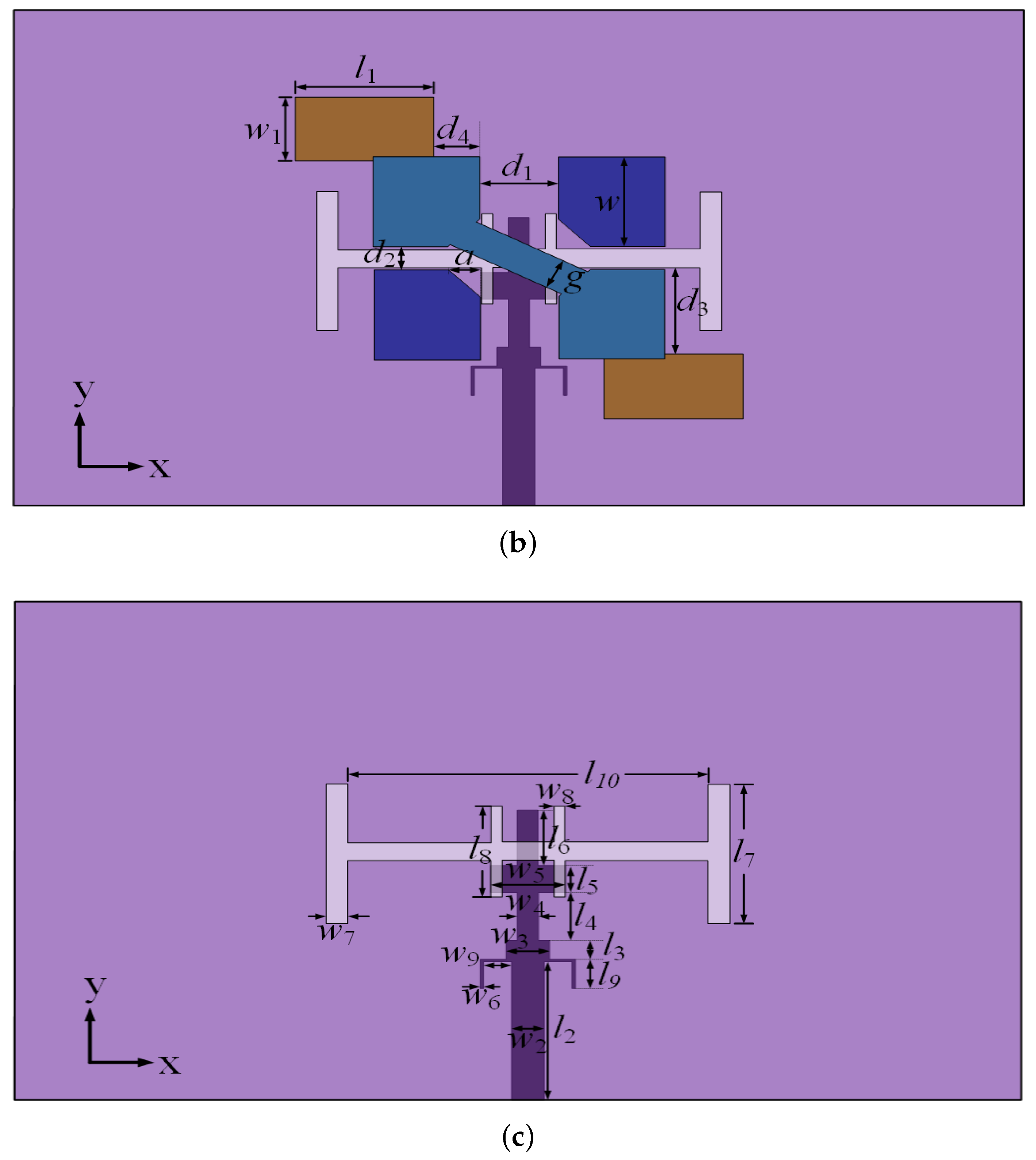
2.1. Antenna Configuration

Figure 1 illustrates the structure of the proposed broadband CP filtering ME dipole antenna. It comprises a pair of crossed metallic ME dipoles, a pair of inverted-L-shaped shorted metallic plates, and a bottom dielectric substrate. The pair of crossed ME dipoles are oriented along the ±45° directions. The ME dipole aligned at −45° is connected via a phase delay line; this configuration is employed to generate CP radiation. To enhance the axial ratio (AR) bandwidth, a pair of inverted-L-shaped shorted metallic plates are placed perpendicular to the ground plane along the −45° direction relative to the ME dipoles. As depicted in Figure 1b,c, the bottom dielectric substrate (FR4) has a metallic ground plane printed on its top surface and a microstrip feed line printed on its bottom surface. By introducing grid slots etched into the metallic ground plane and loading a pair of open-circuited stubs onto the microstrip feed line, two specific radiation nulls are generated in the upper stopband. Combined with the inherent radiation null naturally produced by the antenna structure itself in the lower stopband, this design achieves a good bandpass filtering response. Crucially, this filtering functionality is realized without incorporating any additional external filtering circuits and without altering the fundamental antenna geometry. Based on this structure, a broadband CP ME dipole antenna exhibiting integrated bandpass filtering radiation performance has been achieved.

2.2. Step-by-Step Design Process

To elucidate the operating principle of the proposed filtering CP ME dipole antenna, Figure 2 presents four reference antennas along with their corresponding results. As shown in Figure 2a, Ant.I employs a rectangular slot to excite the orthogonally placed ME dipoles through capacitive coupling, while a λ /4 phase delay line connected to the −45° oriented ME dipole establishes the quadrature phase relationship necessary for LHCP operation at 3.9 GHz. The antenna inherently generates two radiation nulls: a lower stopband null at 2.6 GHz resulting from the crossed E dipoles’ fundamental mode cancellation and an upper stopband null at 7.5 GHz created by the rectangular slot’s half-wavelength resonance, though with limited suppression due to the single-null mechanism. Ant.II in Figure 2b replaces the rectangular slot with grid slots that function as an electromagnetic bandgap structure, shifting the upper stopband null to 6.7 GHz through their periodic unit cell resonance (p ≈ λ /4) while significantly improving the suppression and roll-off rate via the distributed filtering effect. Ant.III in Figure 2c introduces inverted-L-shaped parasitic elements (L ≈ λ /4 at 4.45 GHz) along −45° to create an additional degenerate resonance mode through coupled oscillation with the main dipoles, effectively broadening the CP bandwidth via dual-resonance excitation at 3.9 GHz and 4.45 GHz. The proposed antenna in Figure 2d further incorporates λ /4 open-circuited stubs on the feed line to introduce a third radiation null at 7.25 GHz through transmission line cancellation, completing the triple-null filtering mechanism that achieves good upper stopband suppression (>25 dB) while maintaining broad CP bandwidth performance.

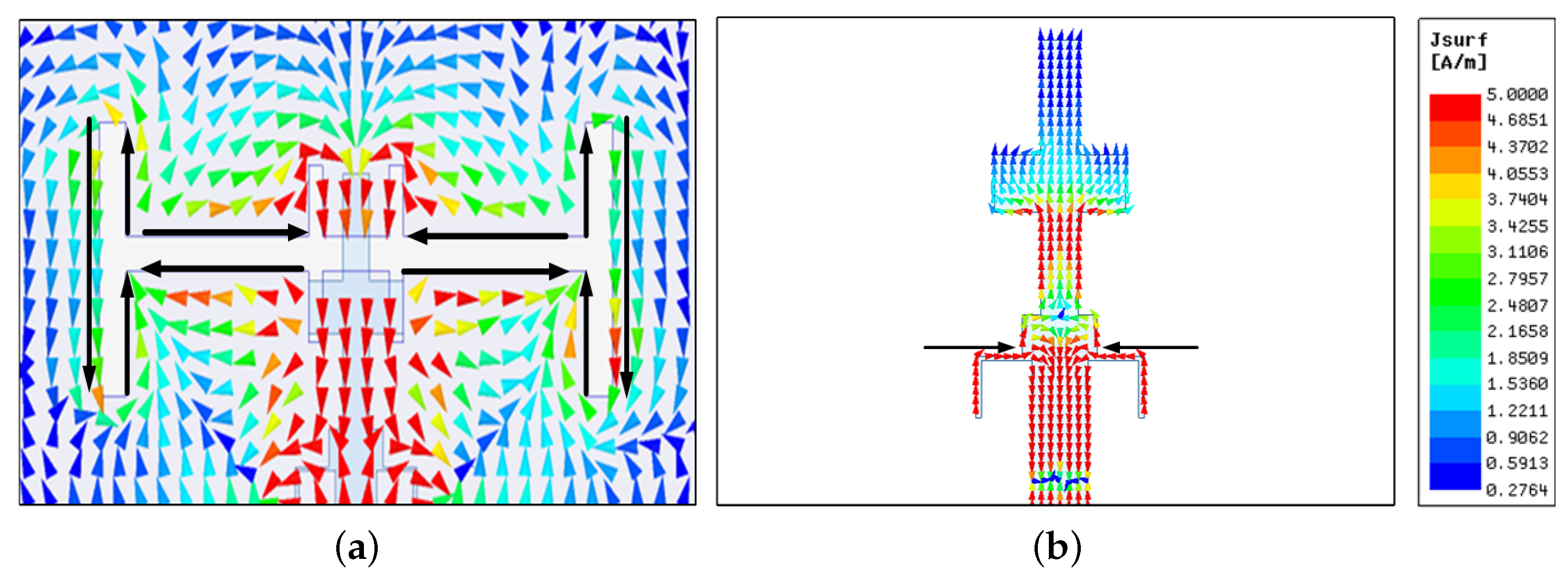
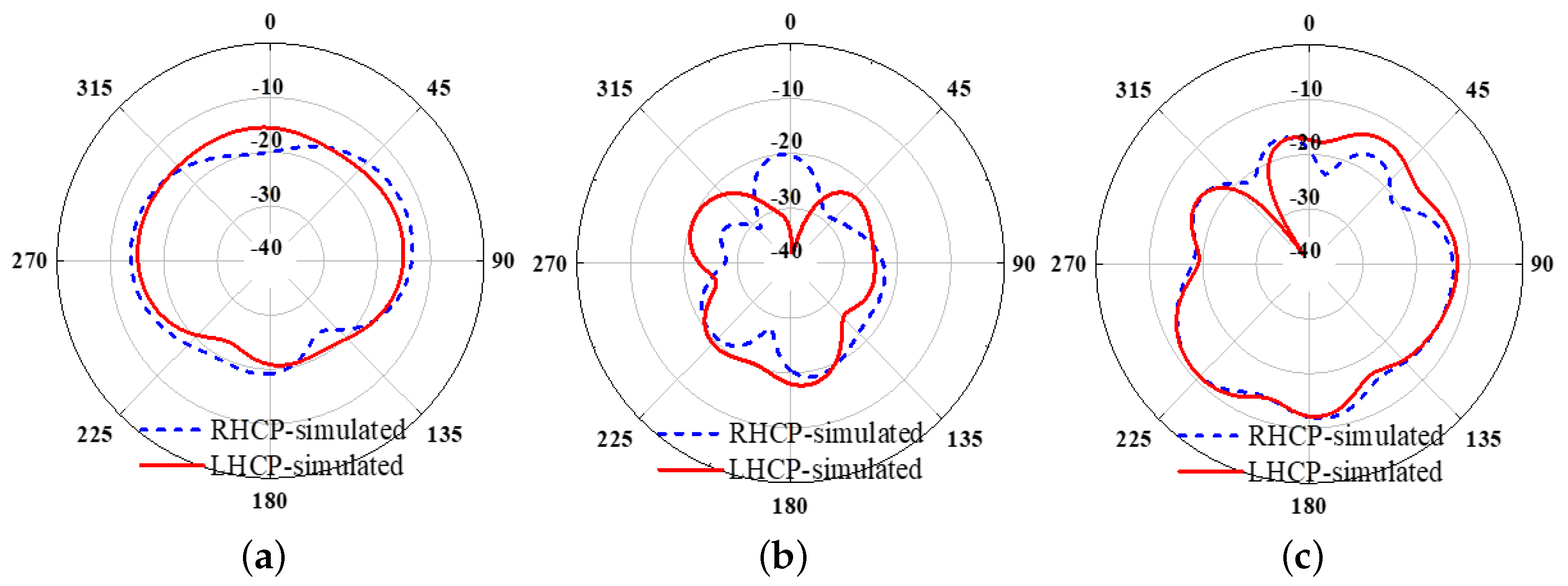
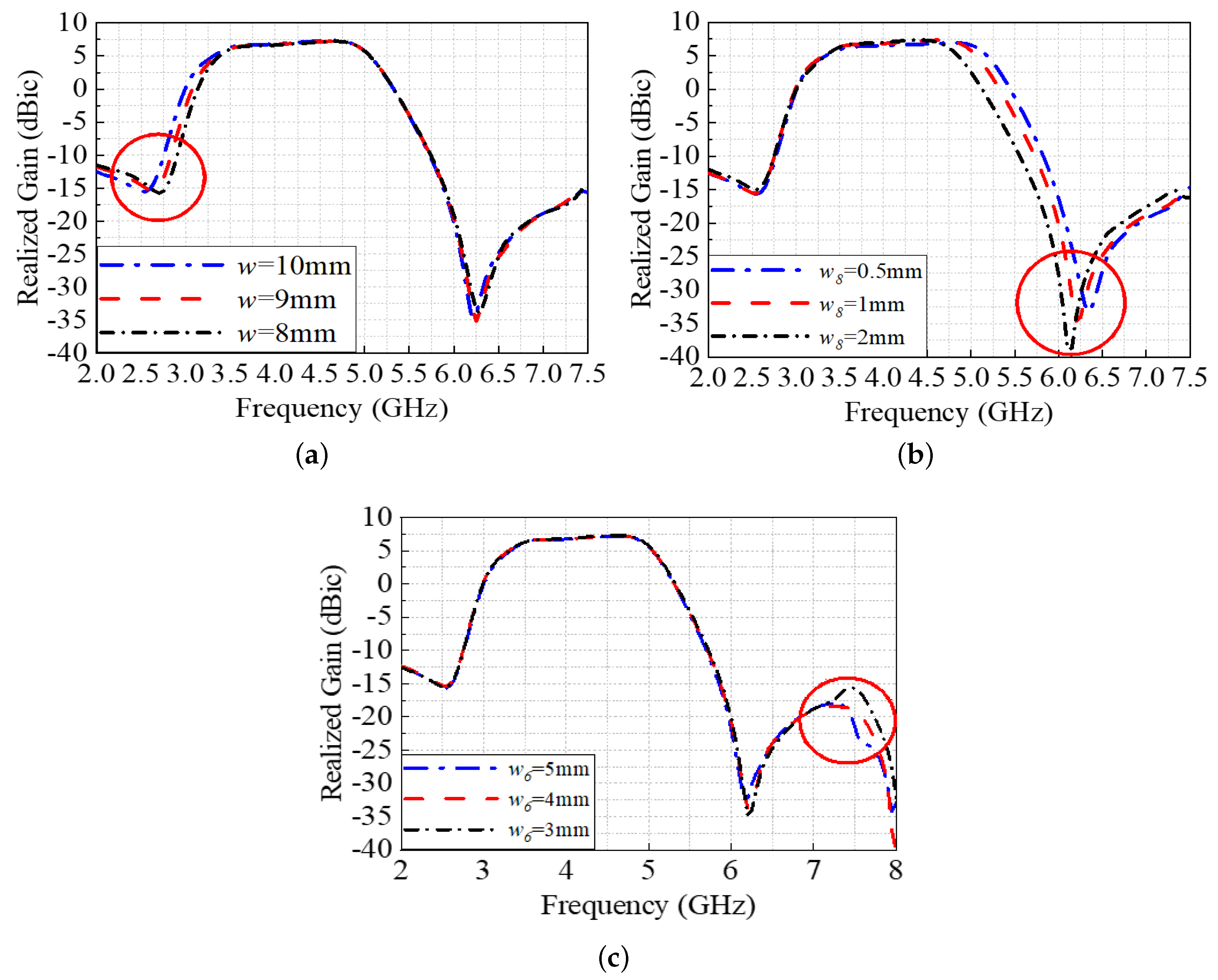
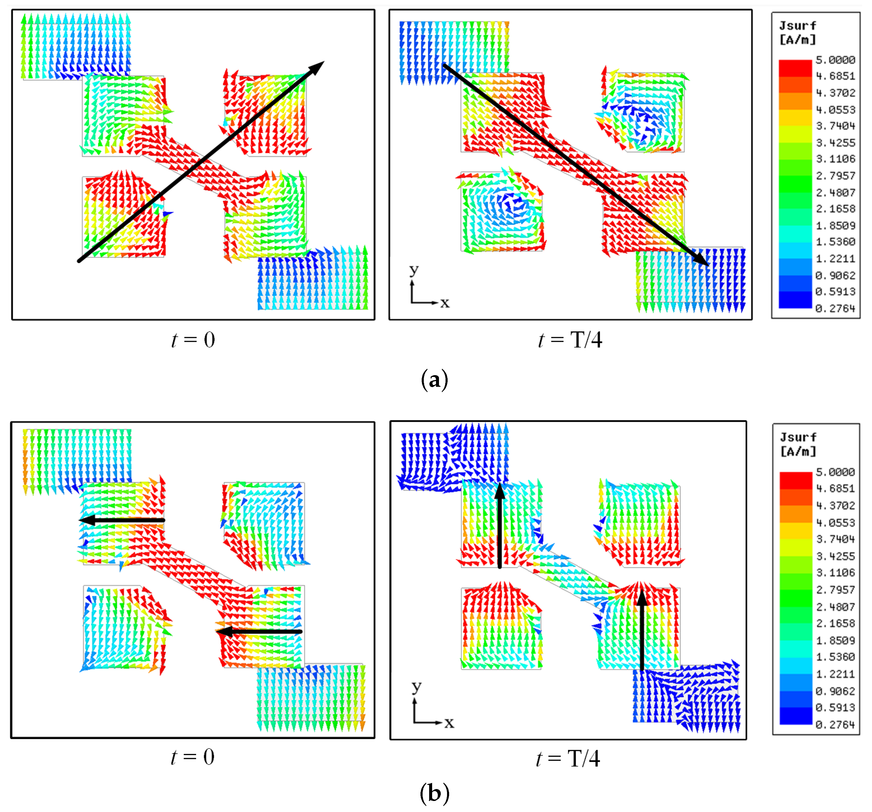
2.3. Analysis of Radiation Nulls and Axial Ratio Performance

The radiation null in the lower stopband is inherently produced by the crossed magnetoelectric (ME) dipoles, as established in [25]. To elucidate the operating principles of the two radiation nulls in the upper stopband, this work analyzes the corresponding surface current distributions, radiation patterns, and parametric variations. Figure 3 presents the simulated surface current distributions of the proposed antenna at its two upper stopband radiation null frequencies (6.20 GHz and 7.25 GHz, when t = 0). At 6.20 GHz, the surface currents are predominantly concentrated on the grid slots and exhibit significant out-of-phase components. Since the grid slots are essentially defect structures on the ground plane, their geometric dimensions determine the resonant frequency. When the incident wave frequency approaches the slot’s resonant frequency, the excited counter-circulating currents around the resonant slots interact with the original ground plane currents to generate oppositely directed radiation components. This results in destructive interference in the far-field, causing a sharp radiation power reduction at this frequency. Conversely, at 7.25 GHz, the currents are mainly localized on the open-circuited stubs of the feed line, where the open-circuit stub, functioning as a terminal-open λ /4 transmission line, exhibits an equivalent short-circuit condition at its resonant frequency. This results in high impedance characteristics that effectively suppress radiation at this specific frequency. The normalized radiation patterns at the three radiation null frequencies (including the lower stopband null) are displayed in Figure 4. It is evident from the figure that both the right-hand circularly polarized (RHCP) and left-hand circularly polarized (LHCP) components fall below −20 dBic at these frequencies, demonstrating effective radiation suppression.
Parametric studies showing the frequency shifts of the radiation nulls with key geometrical variations are provided in Figure 5. As illustrated in Figure 5a, when the planar dimension of the ME dipoles (L) decreases from 10 mm to 8 mm, the lower stopband radiation null shifts from approximately 2.55 GHz to 2.75 GHz, while the two upper stopband nulls remain unaffected. Figure 5b indicates that reducing the width of the grid slots ( w 8 ) causes the radiation null at 6.2 GHz to shift towards higher frequencies. In Figure 5c, when w6 increases from 3 mm to 5 mm, the radiation null at 7.25 GHz shifts to 7.60 GHz, with the other two radiation nulls unchanged. Collectively, the evidence presented in Figure 3, Figure 4 and Figure 5 demonstrates that the three radiation nulls are introduced by the ME dipoles, the grid slots, and the open-circuited stubs, respectively.
Figure 6 and Figure 7 elucidate the generation mechanism of the two circularly polarized operating frequencies in the proposed antenna. Figure 6a,b present the surface current distributions at 3.65 GHz and 4.45 GHz, respectively, captured at t = 0 and t = T/4. The current distributions reveal that at 3.65 GHz, the currents are predominantly concentrated on the crossed ME dipoles and exhibit distinct LHCP characteristics, while at 4.45 GHz, the currents are mainly localized at the coupling region between the inverted-L-shaped shorted metallic plates and the ME dipoles while maintaining the same LHCP properties. Figure 7 demonstrates the parametric effects on the axial ratio frequencies. As the length of the ME dipoles (w) increases, the AR frequency at 3.65 GHz shifts toward the lower band. When the length of the parasitic element ( w 1 ) increases, the 4.45 GHz circularly polarized resonating frequency shifts toward the lower band. Similarly, when increasing the distance between the inverted-L parasitic elements and the crossed dipoles ( d 3 ), the AR frequency at 4.45 GHz shifts to the lower band, which further validates the CP frequency generation mechanism described earlier.

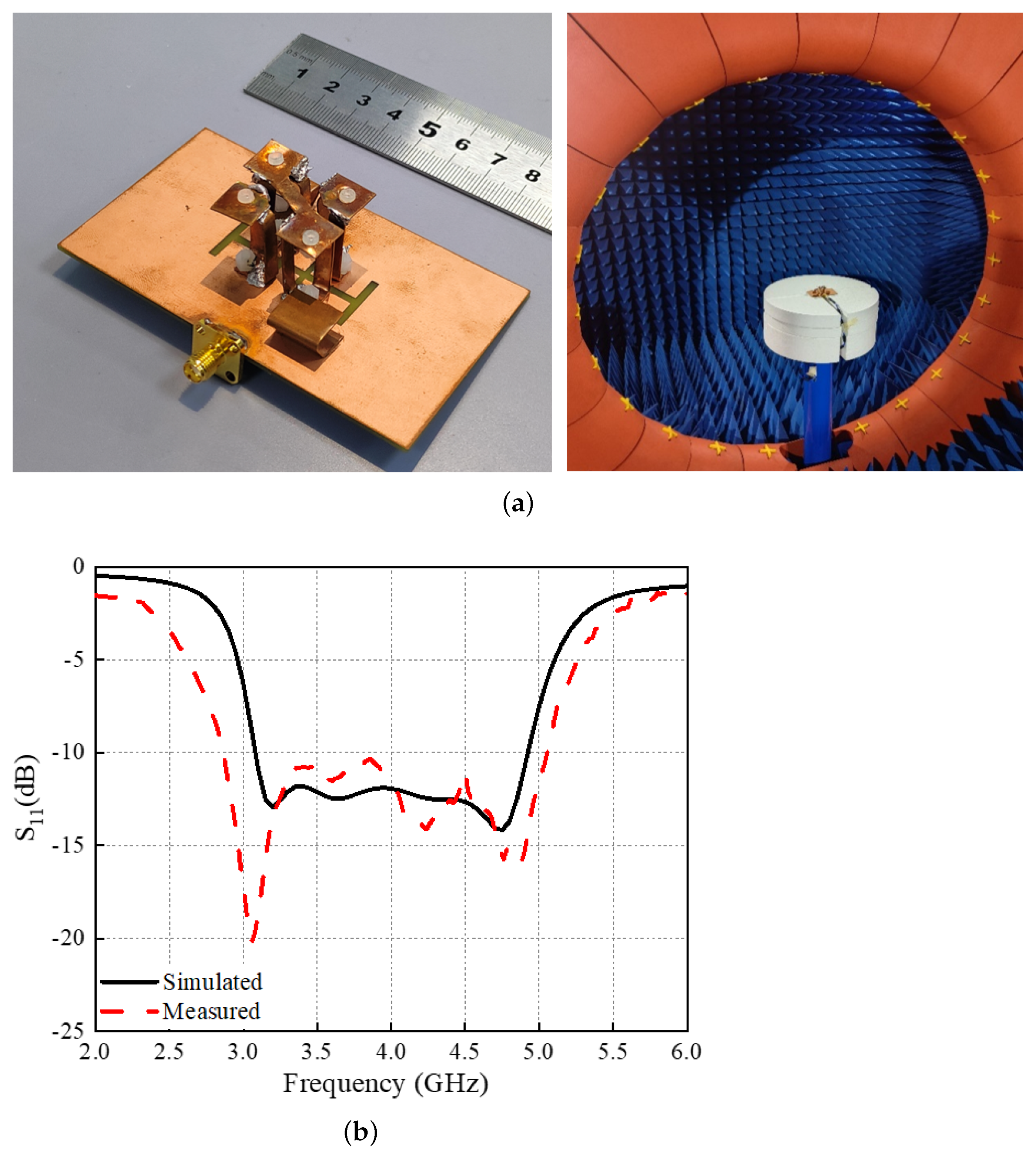
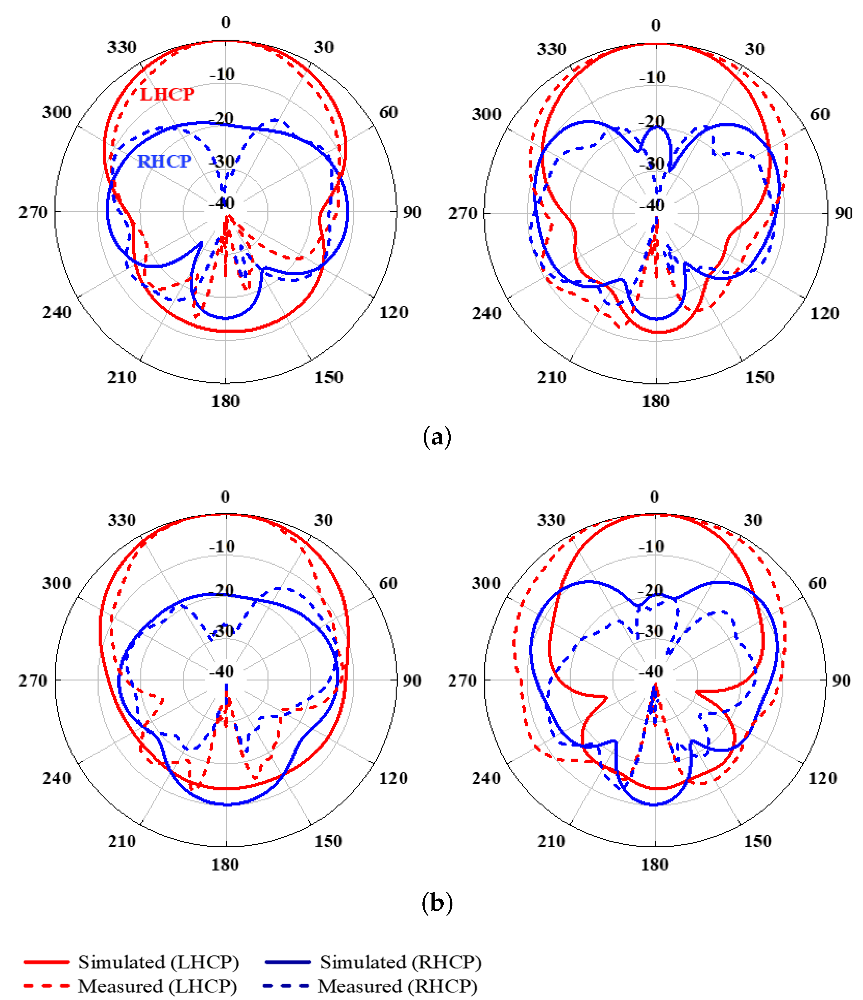
3. Antenna Implementation

Based on the aforementioned design methodology, a broadband circularly polarized (CP) filtering magnetoelectric dipole antenna (ME) was designed, fabricated, and tested, as shown in Figure 8a. The S parameters were measured using an Agilent N5227A (Keysight, Santa Rosa, CA, USA) vector network analyzer, while the axial ratio (AR), gain, and radiation patterns were obtained using a Satimo measurement system (Microwave Vision Group, Paris, France). Figure 8b–d present the simulated and measured S parameters, the realized gain, and the AR, respectively.
The measured results show good agreement with the simulated ones, as illustrated in Figure 8b–d except for minor discrepancies. These variations primarily stem from practical fabrication limitations in PCB production, including but not limited to etching tolerances, dielectric constant variations, and assembly alignment precision. In simulations, the antenna achieves a −10 dB impedance bandwidth of 46.2% (3.06 GHz–4.90 GHz) and a 3 dB axial ratio (AR) bandwidth of 31.9% (3.53 GHz–4.87 GHz), with a relatively stable in-band gain of 6.6 dBi. In measurements, the fabricated antenna exhibits an ( S 11 ) bandwidth of 66.4% (2.87 GHz–5.05 GHz) and an AR bandwidth of 31.9% (3.32 GHz–4.58 GHz), with an average in-band gain of 5.5 dBi. Compared to simulations, the measured impedance bandwidth is significantly broadened by approximately 20.2%. Three radiation nulls are observed at around 2.45 GHz, 6.8 GHz, and 7.5 GHz. Although the out-of-band suppression level in the lower stopband is slightly reduced, the upper stopband maintains a high radiation suppression level. However, the in-band gain decreases by approximately 1.1 dB, which can be attributed to fabrication and measurement tolerances. While the measured AR bandwidth shifts slightly toward lower frequencies compared to simulations, its fractional bandwidth remains nearly unchanged. Figure 9 presents the normalized radiation patterns at 3.5 GHz and 4.35 GHz. As expected, stable radiation patterns with over 20 dB cross-polarization levels are observed within ±30°. Moreover, in the phi = 90° plane, the power difference between the main polarization (LHCP) and the cross-polarization (RHCP) is further enhanced, confirming the antenna’s effective left-hand circular polarization characteristics.
To highlight the merits of the proposed work, Table 1 provides a comparative analysis of relevant CP antennas. The proposed antenna demonstrates superior wideband performance. In [10,11,12], metallic patches serve as radiators, and filtering circuits are employed to achieve CP filtering functionality. However, their operational bandwidths are inherently limited (7.10% in [10], 11.40% in [11], and 21.60% in [12]). In references [16,17,22], bandpass filtering characteristics were achieved in circularly polarized patch antennas through relatively simple modifications including loading parasitic elements, etching slots, or incorporating open-circuited stubs on the microstrip feedline. More advanced approaches in [19,21] combined these slotting or stub-loading techniques with additional filtering methods such as introducing parasitic patches, loading shorting probes, or implementing shorted patches. In [18,20], although relatively wide operating bandwidths were achieved, these designs suffer from several drawbacks including excessive antenna profile height, unstable in-band gain, and poor out-of-band suppression performance. Alternative designs include [23], which employed capacitive coupling between two orthogonally positioned resonators to realize second-order bandpass filtering, and [24], which utilized crossed-dipole radiators with nested square-ring structures to create current cancellation for enhanced out-of-band suppression. While all these circularly polarized filtering antennas successfully demonstrate bandpass filtering functionality, they share a common limitation of exhibiting relatively narrow axial ratio bandwidths. In contrast, the proposed antenna simultaneously attains a wide impedance bandwidth of 66.4%, an AR bandwidth of 31.9%, high out-of-band suppression, and stable in-band gain.
It is worth mentioning that, following the methodology in [26], the roll-off rate of filtering antennas can be quantified using the Gain Suppression Index (GSI) or Radiation Skirt Index (RSI):
G S I = G B W 3 d B G B W 10 d B × f H 3 f L 3 f H 10 f L 10
R S I = E B W 80 % E B W 16 % × f H 80 f L 80 f H 16 f L 16
The proposed antenna exhibits higher GSI/RSI values than most referenced designs, indicating superior filtering performance. However, since many existing CP filtering antennas either omit radiation efficiency data or report efficiencies below 80%, RSI values cannot be calculated for those designs.

4. Conclusions

This paper has presented a broadband circularly polarized (CP) filtering magnetoelectric (ME) dipole antenna featuring a simple yet effective configuration. The fundamental CP radiation characteristics have been achieved through a pair of orthogonally crossed ME dipoles integrated with a phase delay line. By strategically introducing inverted-L-shaped parasitic elements oriented along the −45° direction, the axial ratio (AR) bandwidth has significantly enhanced to 31.9% (3.32–4.58 GHz). The antenna’s high-selectivity bandpass filtering response has been realized through synergistic generation of three radiation nulls: one inherently produced by the ME dipole configuration, another introduced by grid slots etched in the ground plane, and a third created through open-circuited stubs loaded on the microstrip feed line. The experimental results have demonstrated excellent performance metrics, including a measured impedance bandwidth of 66.4% (2.87–5.05 GHz), stable in-band gain of 5.5 dBic, and remarkable out-of-band suppression levels of 11.5 dB and 26.8 dB at the lower and upper stopbands, respectively. The proposed antenna has designed exhibits superior comprehensive performance in both bandwidth and filtering characteristics compared to existing CP filtering antenna solutions, offering a promising approach for integrated RF front-end system design, while future work could explore miniaturization techniques for more compact implementations and investigate the integration of reconfigurable elements to enable tunable filtering characteristics for adaptive wireless systems.

Author Contributions

Conceptualization: X.L. and Z.Z.; Methodology: Z.J. and M.Z.; Software: Z.J. and Z.Z.; Validation: M.Z. and X.L.; Formal Analysis: Z.J. and Z.Z.; Investigation: All Authors; Resources: X.L. and M.Z.; Data Curation: Z.J. and M.Z.; Writing—Original Draft: X.L. and Z.J.; Writing—Review and Editing: All Authors; Visualization: M.Z. and Z.Z.; Supervision: X.L.; Project Administration: Z.Z.; Funding Acquisition: X.L. All authors have read and agreed to the published version of the manuscript.

Funding

This work was supported by the Basic and Applied Basic Research Foundation of Guangdong Province under Grant 2022A1515110663 and Guangdong-Taiwan Technology Cooperation Projects in Guangdong Province Grant No. 2024A0505050044.

Data Availability Statement

The original contributions presented in this study are included in the article. Further inquiries can be directed to the corresponding author.

Conflicts of Interest

The authors declare no conflicts of interest.

References

  1. Mao, C.; Khalily, M.; Tafazolli, R.; Kishk, A. Wideband Dual Circularly Polarized Helical Antenna Array for Satellite Applications. IEEE Antennas Wirel. Propag. Lett. 2024, 9, 2758–2762. [Google Scholar] [CrossRef]
  2. Hou, R.; Ren, J.; Liu, Y.-T.; Cai, Y.-M.; Wang, J.; Yin, Y. Broadband Magnetoelectric Dipole Filtering Antenna for 5G Application. IEEE Antennas Wirel. Propag. Lett. 2023, 3, 497–501. [Google Scholar] [CrossRef]
  3. Li, L.; Xiong, H.D.; Wu, W.Y.; Fu, A.B.; Han, J.Y. A T-Shaped Strips Loaded Wideband Filtering Patch Antenna With High Selectivity. IEEE Antennas Wirel. Propag. Lett. 2024, 1, 89–93. [Google Scholar] [CrossRef]
  4. Zhao, Z.; Qiu, L.-F.; You, B.; Wu, L.-S.; Mao, J.-F. Three-Dimensional Integrated Circularly Polarized Filtering Antenna Array With High-Efficiency Hybrid Feeding Network. IEEE Trans. Antennas Propag. 2024, 8, 6348–6361. [Google Scholar] [CrossRef]
  5. Li, J.-F.; Lin, Y.-Q.; Xue, Y.-M.; Ye, L.-H.; Mao, C.-X. A Shared-Aperture Linearly/Circularly Polarized Filtering Antenna Array With Low Profile. IEEE Antennas Wirel. Propag. Lett. 2024, 11, 3877–3881. [Google Scholar] [CrossRef]
  6. Xiang, K.-R.; Chen, F.-C.; Xue, Q.; Chu, Q.-X. A High-Selectivity Circularly Polarized Filtering Antenna Based on Wavefront Phase Compensation. IEEE Antennas Wirel. Propag. Lett. 2024, 10, 3307–3311. [Google Scholar] [CrossRef]
  7. Paul, V.; Dhwaj, K. A Reflectionless Circularly Polarized High-Gain Microstrip Filtering Antenna With Wideband Response. IEEE Trans. Antennas Propag. 2024, 6, 5384–5389. [Google Scholar] [CrossRef]
  8. Wu, Q.-S.; Tang, X.-Y.; Du, Z.-X.; Zhang, X. An all-metal wideband circularly polarized single-patch antenna based on TM11 mode. IEEE Trans. Antennas Propag. 2023, 10, 8266–8271. [Google Scholar] [CrossRef]
  9. Wu, S.; Li, J.; Yao, J.; Cao, Y.; Yan, S. 3-D Printed Millimeter-Wave Filtering Monopulse Comparator for Dual-Circularly Polarized Antenna. IEEE Antennas Wirel. Propag. Lett. 2024, 12, 4797–4801. [Google Scholar] [CrossRef]
  10. Hu, Y.; Wu, Y.; Wang, G.; Wu, X. A Circularly Polarized, Highly Selective, Harmonic-Suppressed Filtering Antenna for 5G Application. IEEE Antennas Wirel. Propag. Lett. 2024, 12, 4308–4312. [Google Scholar] [CrossRef]
  11. Liu, S.; Wang, Z.; Dong, Y. A Compact Filtering Patch Antenna With High Suppression Level and Its CP Application. IEEE Antennas Wirel. Propag. Lett. 2023, 4, 769–773. [Google Scholar] [CrossRef]
  12. Xu, T.; Li, J.-F.; Ye, L.-H.; Wu, D.-L.; Zhang, G. A Wideband Circularly Polarized Filtering Patch Antenna With Strip Network. IEEE Antennas Wirel. Propag. Lett. 2023, 12, 2826–2830. [Google Scholar] [CrossRef]
  13. Jia, Q.S.; Zhang, W.H.; Han, X.; Huang, Y.M.; Ding, S.; Wang, B.Z.; Bozzi, M. A Broadband Filtering Circularly Polarized Folded Transmitarray Antenna Based on Metasurface. IEEE Antennas Wirel. Propag. Lett. 2023, 10, 2357–2361. [Google Scholar] [CrossRef]
  14. Hu, H.-T.; Chan, K.F.; Chan, C.H. Low-Profile Circular-Polarized Filtering Transmitarray Antenna in V-Band. IEEE Antennas Wirel. Propag. Lett. 2024, 1, 938–943. [Google Scholar] [CrossRef]
  15. Hu, H.-T.; Chan, K.F.; Chan, C.H. High-Gain Dual-Circular-Polarized Filtering Lens Antenna for Low-Cost 60 GHz Applications. IEEE Antennas Wirel. Propag. Lett. 2024, 2, 828–832. [Google Scholar] [CrossRef]
  16. Yang, W.J.; Pan, Y.M.; Zhang, X.Y. A Single-Layer Low-Profile Circularly Polarized Filtering Patch Antenna. IEEE Antennas Wirel. Propag. Lett. 2021, 4, 602–606. [Google Scholar] [CrossRef]
  17. Cheng, G.; Huang, B.; Huang, Z.; Yang, L. A High-Gain Circularly Polarized Filtering Stacked Patch Antenna. IEEE Antennas Wirel. Propag. Lett. 2023, 5, 995–999. [Google Scholar] [CrossRef]
  18. Wang, J.; Zhang, Y.; Ye, L.; Liu, Q.H. A Wideband Circularly Polarized Filtering Antenna Based on Slot-Patch Structure. IEEE Antennas Wirel. Propag. Lett. 2023, 8, 1858–1862. [Google Scholar] [CrossRef]
  19. Cheng, G.; Zhou, J.; Yang, L.; Wu, X.; Huang, Z. A Stacked Circularly Polarized Filtering Antenna With Crossed Slot. IEEE Antennas Wirel. Propag. Lett. 2023, 12, 2935–2939. [Google Scholar] [CrossRef]
  20. Zhou, J.; Pan, X.; Cheng, G.; Yang, L.; Li, Y.; Huang, Z. A Wideband Circularly Polarized Filtering Antenna Based on Multilayer Structural Design. IEEE Antennas Wirel. Propag. Lett. 2024, 11, 3887–3891. [Google Scholar] [CrossRef]
  21. Xiao, Z.; Cao, Y.; Che, W.; Xue, Q. Millimeter-Wave Filtering Circularly Polarized Antenna Using Hybrid Radiation Modes for Satellite Applications. IEEE Antennas Wirel. Propag. Lett. 2024, 11, 7584–7593. [Google Scholar] [CrossRef]
  22. Tang, M.-C.; Li, D.; Wang, Y.; Hu, K.-Z.; Ziolkowski, R.W. Compact, Low-Profile, Linearly and Circularly Polarized Filtennas Enabled With Custom-Designed Feed-Probe Structures. IEEE Trans. Antennas Propag. 2020, 7, 5247–5256. [Google Scholar] [CrossRef]
  23. Cahyasiwi, D.A.; Zulkifli, F.Y.; Rahardjo, E.T. Orthogonal Resonators for Circularly Polarized Filtering Antenna Using a Single Feedline. IEEE Trans. Microw. Theory Tech. 2023, 10, 4227–4235. [Google Scholar] [CrossRef]
  24. Lin, X.J.; Zhang, Y.; Qiu, Z.L.; Huang, Z. A Compact Circularly Polarized Filtering Dipole Antenna With Co-Layered Printed Ring Structures. IEEE Antennas Wirel. Propag. Lett. 2024, 10, 3098–3102. [Google Scholar] [CrossRef]
  25. Wei, S.Z.; Zhou, Z.; Tang, Z.; Yin, J.Y.; Ren, J.; Yin, Y. Broadband Filtering Magnetoelectronic Dipole Antenna With Quasi-Elliptic Gain Response. IEEE Trans. Antennas Propag. 2020, 4, 3225–3230. [Google Scholar] [CrossRef]
  26. Feng, B.; Chen, J.; Chung, K.L.; Wang, L.; Li, Y. Dual-Polarized Filtering Magneto-Electric Dipole Antenna Arrays With High Radiation-Suppression Index for 5G New Radio n258 Operations. IEEE Trans. Antennas Propag. 2022, 4, 3058–3063. [Google Scholar] [CrossRef]
Figure 1. Antenna structure. (a) 3D view. (b) Antenna top view. (c) Ground top view. (G1 = 95, G2 = 55, h = 1.5, h1 = 19, h2 = 7.5, w0 = 3.5, d1 = 7.5, d2 = 2.5, d3 = 9.75, d4 = 4.25, a = 3, g = 4.5, w = 10, w1 = 7, w2 = 3, w3 = 4, w4 = 2, w5 = 7, w6 = 0.3, w7 = 2, w8 = 1, w9 = 2.7, l1 = 13, l2 = 15.3, l3 = 2.15, l4 = 5.35, l5 = 3, l6 = 6, l7 = 16, l8 = 10, l9 = 3.2, l10 = 34, all in mm).
Symmetry 17 01145 g001aSymmetry 17 01145 g001b
Figure 2. Structure and results of four antennas (solid lines: Realized Gain; dashed lines: Axial Ratio).
Symmetry 17 01145 g002
Figure 3. Current distribution of the proposed antenna at two upper-band radiation nulls. (a) 6.20 GHz. (b) 7.25 GHz.
Symmetry 17 01145 g003
Figure 4. Simulated radiation nulls radiation patterns at (a) 2.55 GHz, (b) 6.20 GHz, and (c) 7.25 GHz.
Symmetry 17 01145 g004
Figure 5. Frequency control of the radiation nulls at (a) 2.55 GHz, (b) 6.20 GHz, and (c) 7.25 GHz.
Symmetry 17 01145 g005
Figure 6. Surface current distribution of the proposed antenna when t = 0 and t = T/4 at the CP radiation frequencies. (a) 3.65 GHz. (b) 4.45 GHz.
Symmetry 17 01145 g006
Figure 7. Frequency control of the dual CP moods at (a) 3.65 GHz with w varies, (b) 4.45 GHz with d 3 varies, and (c) 4.45 GHz with w 1 varies.
Symmetry 17 01145 g007
Figure 8. The proposed ME antenna (a) prototype, (b) measured reflection coefficients, (c) measured realized gains, (d) measured AR, and (e) measured radiation efficiency.
Symmetry 17 01145 g008aSymmetry 17 01145 g008b
Figure 9. Radiation patterns of the proposed antenna at (a) 3.5 GHz and (b) 4.35 GHz (solid lines: simulation; dashed lines: measurement).
Symmetry 17 01145 g009
Table 1. Comparison of the proposed and reported CP filtering antennas ( λ 0 is the wavelength at the lowest operating frequency).
Ref.Size
( λ 0 × λ 0 × λ 0 )
Filtering
Methods
Imp./ AR.
BW (%)
Ave Gain
(dB)
Sup.
(dB)
GSI/RSI
 [10]1.11 × 1 × 0.039Filtering phase shifter7.10%/7.09%5.428.7/
26.9
0.892/
N/A
 [11]1.55 × 0.9 × 0.058Filtering phase shifter11.40%/14.29%7.8624.11/
25.92
0.694/
0.71
 [12]0.97 × 0.97 × 0.07Filtering phase shifter21.60%/23.10%6.523/
14
0.626/
N/A
 [16]0.92 × 0.92 × 0.01Parasitic patch4.5%/5.3%7.522.5/
24.5
0.65/
N/A
 [17]0.52 × 0.52 × 0.06Slot15.20%/8.20%6.826.8/
28.2
0.73/
N/A
 [18]0.71 × 0.71 × 0.31Slot58.30%/46.9%7.613.6/
10.1
0.855/
N/A
 [19]0.59 × 0.47 × 0.1Parasitic patch + Slot17.72%/9.32%6.320/
21
0.645/
N/A
 [20]0.51 × 0.51 × 0.26Shorting pin + Slot59.00%/51.80%7.018.08/
15.89
0.934/
0.57
 [21]1.53 × 1.53 × 0.19Shorting patch
+ Open stub
15%/16.40%13.014/
16
0.821/
N/A
 [22]0.38 × 0.38 × 0.025Open stub7%/4.5%626/
20
0.916/
0.44
 [23]0.7 × 0.7 × 0.024Two coupled resonators4.70%/3.20%5.531/
31
0.804/
N/A
 [24]0.8 × 0.8 × 0.17Ring structure25.80%/13.20%7.226.2/
36
0.744/
0.54
Pro.0.96 × 0.55 × 0.17Grid Slot
+ Open stub
66.4%/31.9%5.511.5/
26.8
0.926/
0.58
Disclaimer/Publisher’s Note: The statements, opinions and data contained in all publications are solely those of the individual author(s) and contributor(s) and not of MDPI and/or the editor(s). MDPI and/or the editor(s) disclaim responsibility for any injury to people or property resulting from any ideas, methods, instructions or products referred to in the content.

