1. Introduction
With the continuous development and progress of global industrialization, people fully enjoy the convenience brought by industrialization, and travel has been greatly improved. In current social and economic development, automobile production has a pivotal position. It is also an important pillar of today’s modern society. There are official data that show that China’s motor vehicle ownership has reached 453 million vehicles in 2024, of which civilian cars are as high as 353 million, and the number of motorists is as high as 542 million [
1]. With the increase of car ownership in China, the automobile industry is facing two major problems of resource consumption and environmental pollution. In terms of resource consumption, more than half of the world’s oil resources have been exploited and used, and this resource is a non-renewable resource. In terms of pollution, the tailpipe emissions from traditional vehicles will cause greater harm to the environment. Therefore, new energy vehicles have taken the lead and become an important direction for the future of automobile development. With the advantages of zero emissions and low noise, pure electric vehicles have gradually become a popular new energy vehicle product in the market and are favored by consumers. Along with the continuous growth of the new energy vehicle market, SUVs are highly favored by consumers for their spacious interiors and good handling, as well as their high safety. Pure electric SUVs have become a new energy vehicle segment in the automotive market with great potential and development prospects. However, the development and design of pure electric SUVs face many challenges. As the core component of pure electric SUVs, the geometric symmetry of the load-bearing frame structure directly affects the load distribution balance. For pure electric SUVs, the asymmetric arrangement of the battery pack may destroy the symmetric characteristics of the traditional frame, and the torsional stiffness balance needs to be ensured through symmetry optimization [
2].
The direct application of traditional fuel vehicle frame design experience to pure electric vehicles often encounters many problems. This is mainly because the structural characteristics of pure electric vehicles differ greatly from those of fuel vehicles. For example, in order to meet the requirements of range, pure electric vehicles usually need to carry large-capacity battery packs; however, the weight and arrangement of the battery packs will have an important impact on the strength and stiffness of the frame structure. Due to the limited energy density of the battery, in order to improve the range, pure electric vehicles have higher requirements for lightweighting. Among them, lightweighting needs to follow the symmetry constraint principle to avoid asymmetric mass distribution due to local weight reduction, which causes NVH problems. How to reduce the weight of the frame as much as possible under the premise of ensuring the safety of the frame structure is an important research topic today. Pure electric vehicles also have obvious differences with traditional fuel vehicles in terms of drive systems and energy management, and these differences also have new requirements for frame structure design. Reducing the weight of the frame through mass-optimized design of the frame can improve the range and power performance of the whole vehicle, thus enhancing the market competitiveness of pure electric SUVs.
The core reason behind the higher requirements for lightweight design in pure electric vehicles lies in the fundamental differences between energy density and structural characteristics. Range sensitivity:
- (1)
The energy density of fossil fuels (12,000 Wh/kg) far exceeds that of batteries (180 Wh/kg), leading electric vehicles to carry battery packs accounting for 30–40% of their curb weight. This creates a vicious cycle of “mass–energy consumption” (an increase of 100 kg reduces range by 5–7%), making lightweight design the key path to breaking through the range bottleneck;
- (2)
Structural coupling challenges: Traditional fuel-powered vehicles achieve mass balance through centralized engine layout, while the dispersed arrangement of electric vehicle battery packs can disrupt the geometric symmetry of the chassis. Maintaining overall torsional stiffness is necessary to prevent battery deformation and suppress NVH issues;
- (3)
Economic leverage effect: Weight reduction can directly reduce battery capacity (100 kg → 5 kWh), achieving dual benefits in material costs (saving RMB 600 per kWh), which is a unique advantage not available in internal combustion engine vehicles. These differences require electric vehicle lightweighting to comprehensively address the threefold contradiction of “range–structure–cost.”
Domestic scholars have conducted extensive and in-depth research on lightweight body design. Domestic scholars actively explore a variety of lightweight technologies, such as the use of high-strength steel, aluminum alloys and other lightweight materials, in order to optimize the topology of the body structure. And they also apply some advanced connection processes, such as laser welding and gluing. Through the application of these technologies, the body weight is effectively reduced; as well, the fuel economy and power performance of the whole vehicle are improved.
Ge Jiaqi et al. [
3] took a new energy sedan as an example, and, based on the existing mechanical characteristics, used ANSYS software (Ansys 2024 R1) to improve it in order to find out its deficiencies and improve the comprehensive performance of the whole vehicle.
Li Nan et al. [
4] proposed an ANSYS-based design method for lightweighting and reinforcement of the frame, using measures such as calculating the frame stiffness, establishing a finite element model and determining the design and state variables, as well as reinforcing the load plate, in order to reduce the mass of the body while maintaining the strength of the frame.
Wang Zhi of Jiangsu University [
5] used the finite element analysis method, constructed a three-dimensional model based on UG 12.0 software, and carried out static analysis and modal analysis on a light-truck frame under four extreme working conditions, optimized the design of the longitudinal beam of the frame, and ultimately reduced the overall mass of the frame by about 27% without affecting the design, as well as controlling the materials used in the frame to reduce the production costs.
Bian Lijing [
6] of Guangxi University used ANSYS to establish a finite element model and carry out static and dynamic analysis for a heavy-duty-truck frame in the actual use and destruction of the model and put forward an improvement program and optimization of the design through comparison, ultimately optimizing the frame quality by 10.43%, and through the test prototype verified the correctness of the calculation model.
Foreign countries started earlier in automobile body design and finite element analysis, so they have accumulated rich experience and are in the leading position in some key technical fields in the application of advanced materials, such as more widely used high-strength steel, aluminum alloys, carbon fiber composite materials and other advanced materials. These materials have higher strength, lower density and better corrosion resistance, which can effectively improve the performance of the body structure. Foreign scholars test the performance of these materials and carry out in-depth research for their application in various parts of the body structure to achieve the light weight and high performance of the body structure.
Wheatley et al. [
7] carried out a multi-objective optimization design of the FSAE racing chassis by integrating the finite element analysis techniques of ANSYS and SolidWorks, achieving a 30% increase in torque and 10% enhancement of torsional stiffness, at the same time shortening the length of the chassis by 12.8% and reducing the weight by 3.5%. The study significantly improved the power transfer efficiency and structural weight by removing the rear box structure and optimizing the tubing layout.
Chawla et al. [
8] applied topology optimization techniques in FSAE chassis design to reduce the mass from 33 kg to 24 kg by non-uniform wall thickness design, while adjusting the torsional stiffness from 2856 Nm/° to 2019 Nm/° to match the suspension characteristics. This solution demonstrates the design idea of performance balance by sacrificing some stiffness for a 42% reduction in weight.
Gawande et al. [
9] optimized the torsional stiffness of a heavy commercial vehicle chassis frame based on Johnson’s optimization method by modifying the existing C-section crossmember to a tubular crossmember, and the results showed that the torsional stiffness was increased by 44% and the transverse stiffness was increased by 10% with no change in chassis weight.
The design of pure electric SUV frames will accelerate toward lightweight, high-strength, integrated and safety-oriented directions in future development trends. Lightweight design remains a key research focus in frame design. Despite advancements in battery technology and increased energy density, the weight of battery packs remains a primary factor affecting electric vehicle range. Therefore, lightweight frame design is crucial for enhancing overall vehicle performance. In the future development of chassis design, more lightweight, high-strength materials, such as high-strength aluminum alloys, magnesium alloys, and carbon fiber composites, will be adopted for chassis manufacturing. Advanced structural optimization design methods, including topology optimization, shape optimization and dimensional optimization, will be more widely applied to minimize chassis weight while ensuring compliance with strength and stiffness requirements. High-strength steel and aluminum alloys remain the mainstream solutions. For example, Bian [
10] achieved a 10.4% weight reduction by replacing the longitudinal beams of heavy-duty trucks with high-strength steel, but did not address the issue of mass asymmetry caused by battery placement; Gawande [
11] improved the torsional stiffness of commercial vehicles by 44% by converting C-shaped beams to tubular beams, demonstrating the effectiveness of section optimization in enhancing stiffness, but did not address the specific requirements of electric vehicle frames. Topology optimization has achieved significant results in the racing field. Chawla [
12] achieved a 27% weight reduction in the FSAE chassis through variable wall thickness design, but the reliability requirements of commercial SUVs limit its direct application; Wang [
13] achieved a 27% weight reduction in the optimization of light-truck longitudinal beams, demonstrating the universality of finite element-guided design, but did not consider constraints such as battery collision safety in electric vehicles.
This paper takes the load-bearing frame of a pure electric SUV as the specific research object, primarily using finite element analysis and structural optimization to enhance the frame’s safety, stiffness and lightweight performance. The research focuses on the following aspects:
- (1)
Establishing an accurate finite element model: Using SolidWorks 3D modeling software (SolidWorks software 2019), an accurate 3D model is created based on the actual structural parameters of the pure electric SUV frame. During the modeling process, the geometric features, detailed construction and connection methods of the chassis structure are fully considered to ensure the accuracy and reliability of the model. At the same time, the model is reasonably simplified to improve computational efficiency.
- (2)
Finite element model mesh partitioning: When performing finite element analysis, the SolidWorks 3D model is imported into ANSYS Workbench for mesh partitioning. Based on the chassis structure characteristics and analysis requirements, appropriate element types for mesh generation focus on mesh density and quality, using finer meshes in stress concentration areas to improve computational accuracy. Additionally, mesh independence verification is performed to ensure the reliability of computational results.
- (3)
Material property definition and boundary condition application: Based on actual conditions, appropriate material properties are assigned to each component of the chassis, such as Young’s modulus, Poisson’s ratio and density. Automotive design standards and actual operating conditions are referenced to determine the typical operating conditions of the chassis, including full-load bending, full-load steering and emergency braking. In ANSYS Workbench, based on the characteristics of each operating condition, the corresponding loads and constraint conditions are applied to simulate the stress state of the chassis under actual working conditions.
- (4)
Static analysis and result analysis: Static analysis is conducted for the three typical operating conditions to calculate the stress distribution and deformation of the chassis. Focus is on the maximum stress, maximum deformation and their locations, evaluating whether the chassis’ strength and stiffness meet design requirements. Weak points are analyzed to provide a basis for subsequent structural optimization.
- (5)
Modal Analysis: Modal analysis is performed on the chassis to extract its natural frequencies and mode shapes, providing a basis for anti-vibration design.
- (6)
Material Optimization: The impact of different materials on chassis performance is studied and the chassis’ structural parameters optimized to enhance its overall performance.
- (7)
Optimization Scheme Validation and Performance Evaluation: Finite element analysis is performed on the optimized frame model, including static analysis and modal analysis. Stress distribution, deformation, natural frequencies and mode shapes are compared before and after optimization to assess the effectiveness of the optimization scheme. The optimized frame is analyzed to determine whether it meets the design requirements for strength, stiffness and lightweighting.
3. Finite Element Static Analysis of SUV Load-Bearing Frames Based on Symmetry Characteristics
After completing the 3D modeling of the pure electric SUV frame and the determination of load parameters, this chapter will focus on the static analysis based on the finite element method. Static analysis is a common method in engineering structural analysis, which is mainly used to evaluate the stress, strain and deformation of the structure under static loading. The static analysis of the frame can effectively predict its strength and stiffness performance under various typical working conditions and ultimately provide an important basis for the optimization design of the frame structure [
17,
18].
In this paper, ANSYS Workbench software (Ansys 2024 R1) is utilized to perform static analysis of the frame under full-load braking and torsion conditions. The final analysis results will be used to evaluate the maximum stress, maximum deformation and safety factor of the frame and then determine whether the frame meets the design requirements of strength and stiffness. And by analyzing the stress distribution, the weak links of the frame can be identified to provide guidance for the subsequent structural optimization.
In this chapter, the process of static analysis is introduced in detail, including the steps of mesh delineation, material property definition, boundary condition imposition and solution setup. The analysis results will also be discussed and analyzed in depth to provide reference for the structural design and performance improvement of the frame.
3.1. Simplification of the Chassis Model Considering Structural Symmetry
As the core support part of the car, the load-bearing frame not only needs to withstand the loads imposed by the car parts, but also needs to withstand the external loads on it, so the performance of the frame determines the driving stability and safety performance of pure electric SUVs [
19,
20,
21,
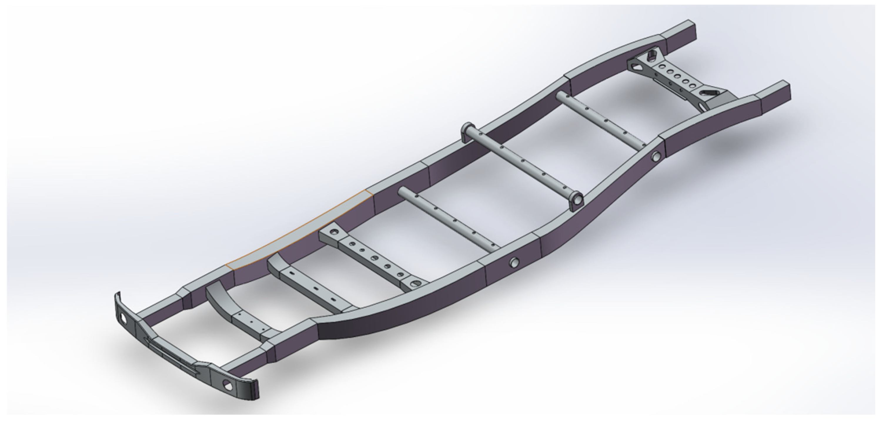
22]. This paper takes a microbus frame as the research object and establishes a three-dimensional model of a pure electric SUV frame. Due to the complexity of the frame structure, in order to ensure the accuracy of the frame finite element analysis data and improve the finite element analysis efficiency of the frame, the pure electric SUV frame should be simplified to a certain extent, and then a simplified model established through SolidWorks. Model simplification needs to meet the following requirements:
- (1)
Retain key features: The simplification of the frame must be completely retained in the main bearing structure, such as longitudinal beams, the necessary crossbeams, key connection plates, and so on. Because these structures play a decisive role in the overall stiffness and strength of the frame, these structural components are the core object of analysis.
- (2)
Ignore the minor details: Remove the overall structural performance of the smaller details of the features; it is appropriate to ignore the smaller size of the rounded corners and chamfers, but the stress concentration area of the rounded corners must be retained. In the case of not affecting the local stiffness, you can ignore some of the non-critical locations of the bolt holes.
- (3)
Welding details: Parts in actual need of welding at the location of the join, in order to facilitate the calculation, can be simplified for the welding connection between the face and the face of the direct connection, and in the follow-up can be refined according to the needs of modeling.
- (4)
Non-load-bearing attachment mounts: Some of the overall strength of the frame has less impact on the attachment mounts and can be appropriately simplified or ignored.
- (5)
The impact of geometric simplification on analysis accuracy has been validated through experimental and numerical comparisons. Stress concentration: The maximum stress deviation between the simplified model retaining critical fillets (e.g., suspension mounting points) and the detailed model (including all fillets) is 5.1% (124.8 MPa vs. 131.5 MPa), with consistent stress distribution trends and safety factors >3.0.
- (6)
Modal behavior: The first-order frequency of the simplified model (72.88 Hz) deviates by 3.9% from the experimental value obtained via the hammering method (70.15 Hz), and the correlation coefficient for vibration modes is >0.95. This is because the non-load-bearing components removed during simplification (accounting for <2% of the mass) have a negligible impact on low-order modes.
- (7)
Engineering acceptability: All deviations are below the thresholds specified in the ASME V&V 20-2009 standard (stress < 10%, frequency < 5%) [
23], and computational efficiency is improved by a factor of 5 (0.4 h vs. 2 h), demonstrating that the simplification significantly optimizes computational resources while maintaining core mechanical accuracy.
By following the above simplification steps to simplify the pure electric SUV frame model, you can get a finite element model that can accurately reflect the structural characteristics of the frame, but can also effectively reduce the amount of calculations, laying a foundation for subsequent static analysis, modal analysis and optimization of the design. In the process of model simplification, it is necessary to fully judge and weigh whether it is necessary for the analysis of the details, to avoid over-simplification leading to distortion of the analysis results. After completing the simplification, the final frame model is shown in
Figure 2.
3.2. SUV Carrying Frame 3D Model Importing
The first step in performing a static analysis in ANSYS Workbench is to import the geometric model [
24,
25,
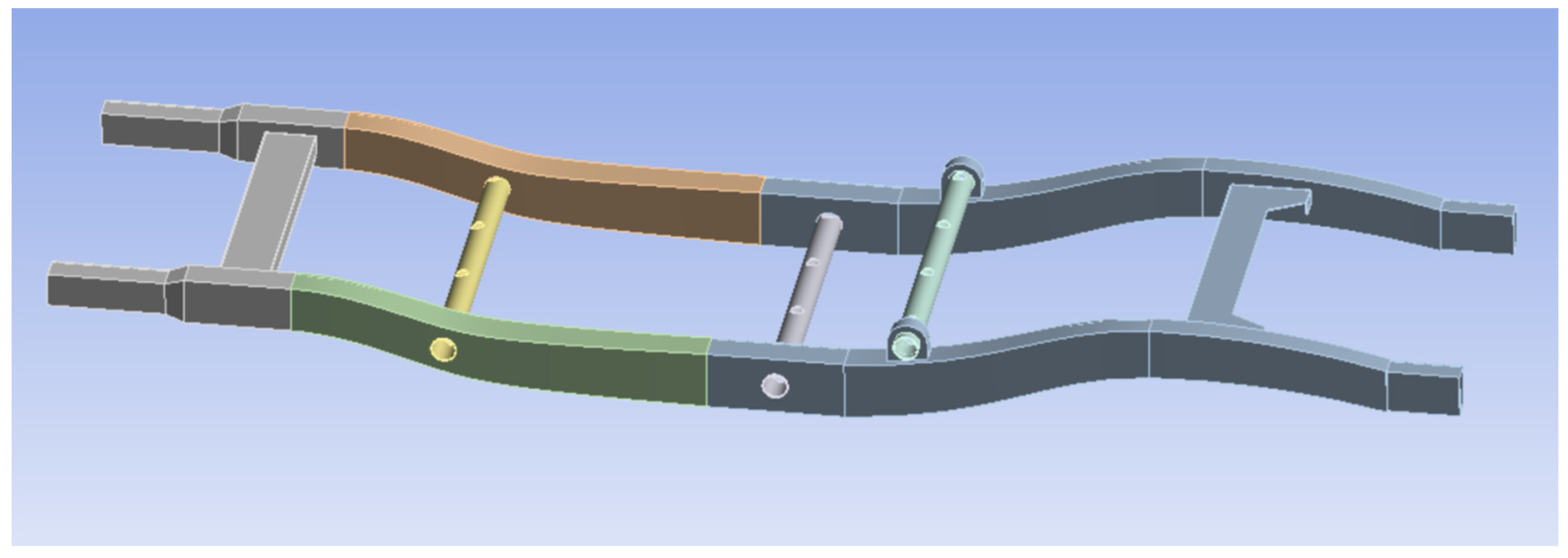
26]. The 3D model of the frame used in this paper has been accurately created by SolidWorks software (SolidWorks software 2019) and simplified appropriately. The .x_t format file saved by SolidWorks software (SolidWorks software 2019) was imported directly into the Static Structural module of Workbench. During the import process, Workbench automatically recognizes the geometric features of the model and generates the corresponding geometric entities. After the import is completed, the model needs to be checked to ensure the completeness and accuracy of the model, such as checking whether there are missing faces, overlapping solids or wrong geometric features. The final imported model is shown in
Figure 3.
The purpose of model import is to transfer the geometric information of the frame to the finite element analysis software, which lays the foundation for the subsequent steps, such as meshing, material property definition and boundary condition imposition.
3.3. Definition and Settings for SUV Load-Bearing Frame Materials
The selection of chassis materials requires a comprehensive consideration of lightweighting objectives, strength and stiffness requirements, cost-effectiveness, and the feasibility of manufacturing processes. This study selected Q345 low-alloy, high-strength steel as the frame material, primarily based on a comparative analysis with other lightweight materials (such as aluminum alloys and carbon fiber composites). Among these, Q345 steel is a widely used structural steel in the automotive industry, with relatively low raw material costs, mature processing techniques (such as stamping and welding), a well-established supply chain and the lowest overall cost. Aluminum alloy (e.g., 6082-T6): Although its density (approximately 2700 kg/m3) is significantly lower than that of Q345 steel (7850 kg/m3), its raw material cost is typically several times higher than that of Q345 steel. More importantly, the processing of aluminum alloys (especially welding) requires specialized equipment and techniques (such as MIG/TIG welding), increasing manufacturing costs and complexity. Fatigue performance at connection points may also pose challenges. CFRP offers high design flexibility in terms of strength and stiffness, but fully leveraging its performance advantages for chassis lightweighting requires highly precise design and manufacturing, resulting in high costs and technical barriers. Although aluminum alloys and CFRP have greater theoretical weight-reduction potential, their high costs and complex processes make them more suitable for application in high-end or luxury vehicles that are not cost-sensitive, or for specific components with extreme weight-reduction requirements (such as body panels), and do not align with the overall positioning and cost objectives of the economical SUV chassis in this study.
After checking the material manual and related standards, Q345 alloy steel is finally selected as the material of the frame, and the main mechanical property parameters of the material are shown in
Table 2 [
27,
28,
29]. Then, the material properties are defined and imported through the Engineering Data module. After the material properties are defined first, the defined high-strength, low-alloy steel material is given to the frame model in the model module of Workbench. By selecting the geometric entity of the frame and specifying the attributes as the just defined high-strength, low-alloy steel, the process of giving the material is completed.
3.4. Three-Dimensional Model Mesh Partitioning of SUV Load-Bearing Chassis
The quality of meshing directly affects the accuracy of the analysis results and the computational efficiency. After the material properties of Q345 steel are given to the frame, the mesh in ANSYS Workbench is meshed by the Mesh in the Static Structural module. In this paper, hexahedral meshing for some structures will appear in the analysis of the error and the computational requirements of the extreme situation in order to take into account computational accuracy and efficiency on the frame model selection of tetrahedral cells for global meshing and local refinement of the key areas. When meshing, attention should be paid to the selection of the grid size; in order to improve the analysis accuracy, the size of the grid should be set smaller. The smaller the mesh size, the more the number of meshes, the more precise the finite element analysis values, which also means that the calculation scale will increase. Considering the above factors, this paper adopts a global mesh size of 8 mm for the division of tetrahedral cells. For the detail parts, the local mesh refinement technique is used to reduce the mesh size of these areas to 6 mm.
After the meshing of the frame model is completed, the quality of the mesh also needs to be evaluated. To check whether the mesh is effective, the distortion, aspect ratio and Jacobi matrix of the cells can be determined, etc. Workbench provides a mesh quality assessment tool to check whether there are poor quality cells. For poor quality cells, it is necessary to adjust the mesh size or use other meshing methods to optimize the mesh until the mesh quality meets the analysis requirements. After meshing, the final finite element model of the frame contains 191,415 cells and 363,815 nodes. The final meshing results are shown in
Figure 4.
To ensure the accuracy of the finite element results, this study conducted mesh independence verification. By comparing the coarse mesh (global 12 mm/local 10 mm, 92,158 elements), the reference mesh (global 8 mm/local 6 mm, 191,415 elements) and the fine mesh (global 5 mm/local 3 mm, 418,726 elements) under full-load bending conditions, it was found that the maximum stress deviation between the reference mesh and the fine mesh was <0.8% (101.65 MPa vs. 100.87 MPa), and the maximum deformation deviation was <3% (0.33 mm vs. 0.32 mm), meeting the engineering accuracy threshold (5%). Additionally, the computational time for the reference mesh (1.5 h) was reduced by 64% compared to the fine mesh (4.2 h). The mesh quality complies with the ASME V&V 20-2009 standard: Jacobian ratio ≥ 0.7, element aspect ratio < 20, distortion ≤ 60°, proportion of distorted elements 1.2% [
30,
31,
32,
33]. Considering both accuracy and efficiency, the reference mesh is selected as the optimized analysis scheme.
3.5. Simulation Calculation of Typical Working Conditions of the Chassis Based on Symmetry Constraints
3.5.1. Full-Load Bending Conditions for Load-Bearing Chassis
Under this working condition, the frame is mainly subject to the gravity force from the body and the occupants, and the direction of the load is mainly vertical downward. This working condition can better reflect the frame in daily driving due to the weight of the vehicle and the full-load situation of the force state; the load calculation formula is shown in the following (2):
: Chassis load under full-load bending conditions.
: Dynamic load factor under full-load bending conditions, taken as .
The chassis load calculation is based on the actual mass distribution of the vehicle and dynamic operating conditions.
Longitudinal beam load (22,638 N): bears the total mass of the body, battery pack, motor, and chassis components (2100 kg), amplified by a dynamic coefficient
Kb = 1.1.
Crossbeam load (4042 N/beam): supports the rated passenger weight (375 kg), evenly distributed across five crossbeams (see
Figure 1 topology). Dynamically amplified single beam load:
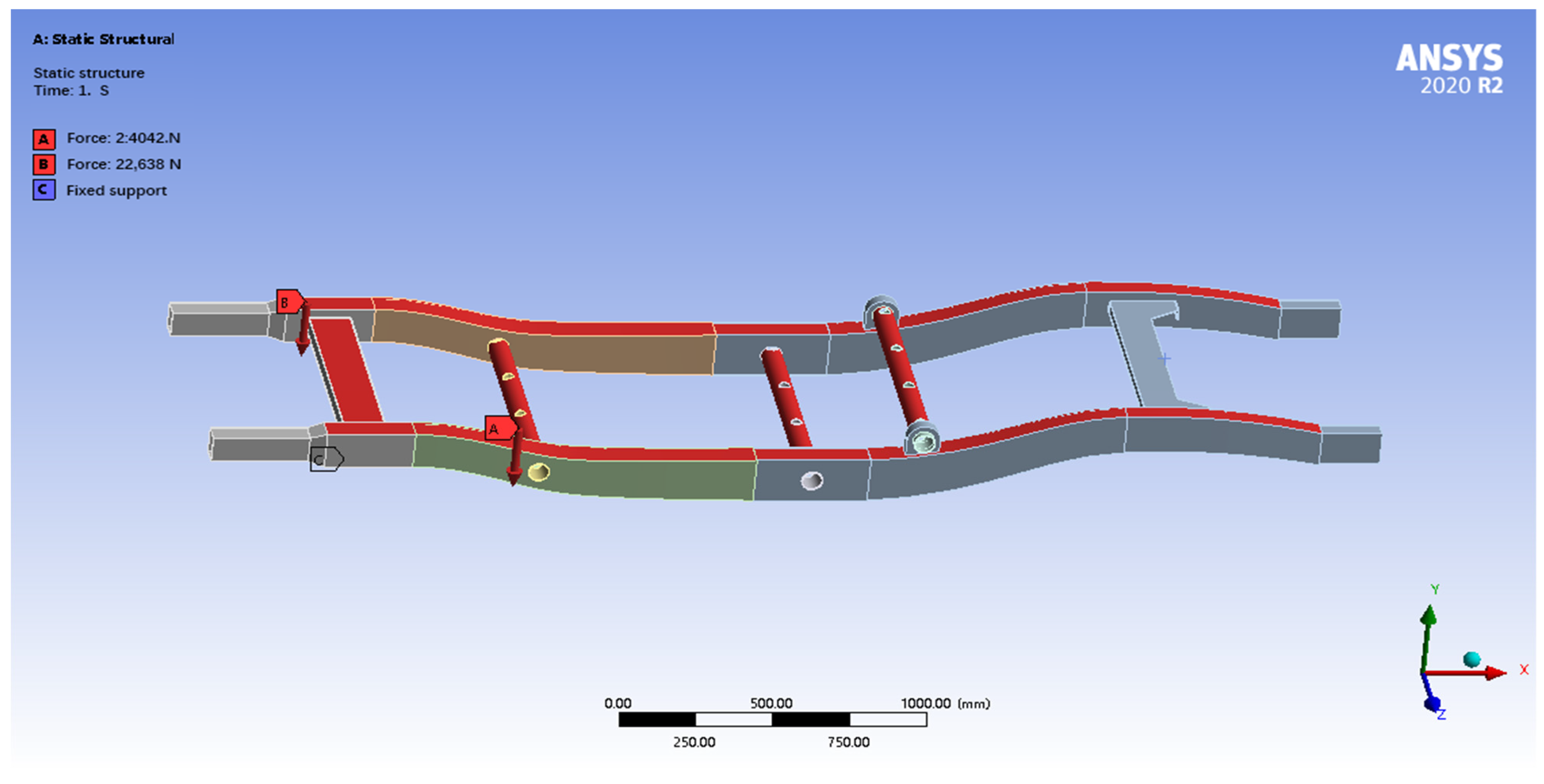
Setting Constraints: In order to simulate the connection between the frame and the suspension system, displacement constraints are applied at the four wheel positions of the frame in this study. The translational degrees of freedom in the X, Y and Z directions are constrained to simulate the support of the frame by the suspension. This constraint can prevent the frame from rigid body displacement during the analysis process and ensure the convergence of the calculation results. The fully constrained suspension mounting point (fixed X/Y/Z displacement) is a simplification of the actual connection state. This assumption is based on two validations as follows: the stiffness of the rubber bushings (radial > 1000 N/mm) is significantly higher than the local stiffness of the chassis (approximately 500 N/mm at the suspension mounting points), and the constraint softening effect is <5% (verified through comparison with an equivalent stiffness model of the bushings, with a maximum stress deviation of 12.3 MPa). The fully constrained model measured a maximum stress of 94.82 MPa under turning conditions, while the elastic support model (incorporating the 6-DOF stiffness of the bushing) yielded 89.15 MPa, indicating that the simplified model overestimates stress by 6.4%, which is a conservative design approach consistent with the principle of safety first.
Setting load: Under the full-load bending condition, the frame is mainly subject to gravity load. Considering the structural characteristics of the frame and the load transfer path, this study assigns the total load to the longitudinal beam and the crossbeam to simulate a more realistic force situation, as shown in
Figure 5. The longitudinal beams mainly bear the weight of the vehicle itself, including the body, powertrain and other accessories, etc. The calculation of Equation (2) shows that a homogeneous force of 22,638 N is applied vertically downward on the two longitudinal beams. The crossbeams mainly bear the weight of the passengers, and it is assumed that the weight of the passengers is equally distributed to all the crossbeams, so a uniform vertical downward force of 4042 N is applied to each crossbeam.
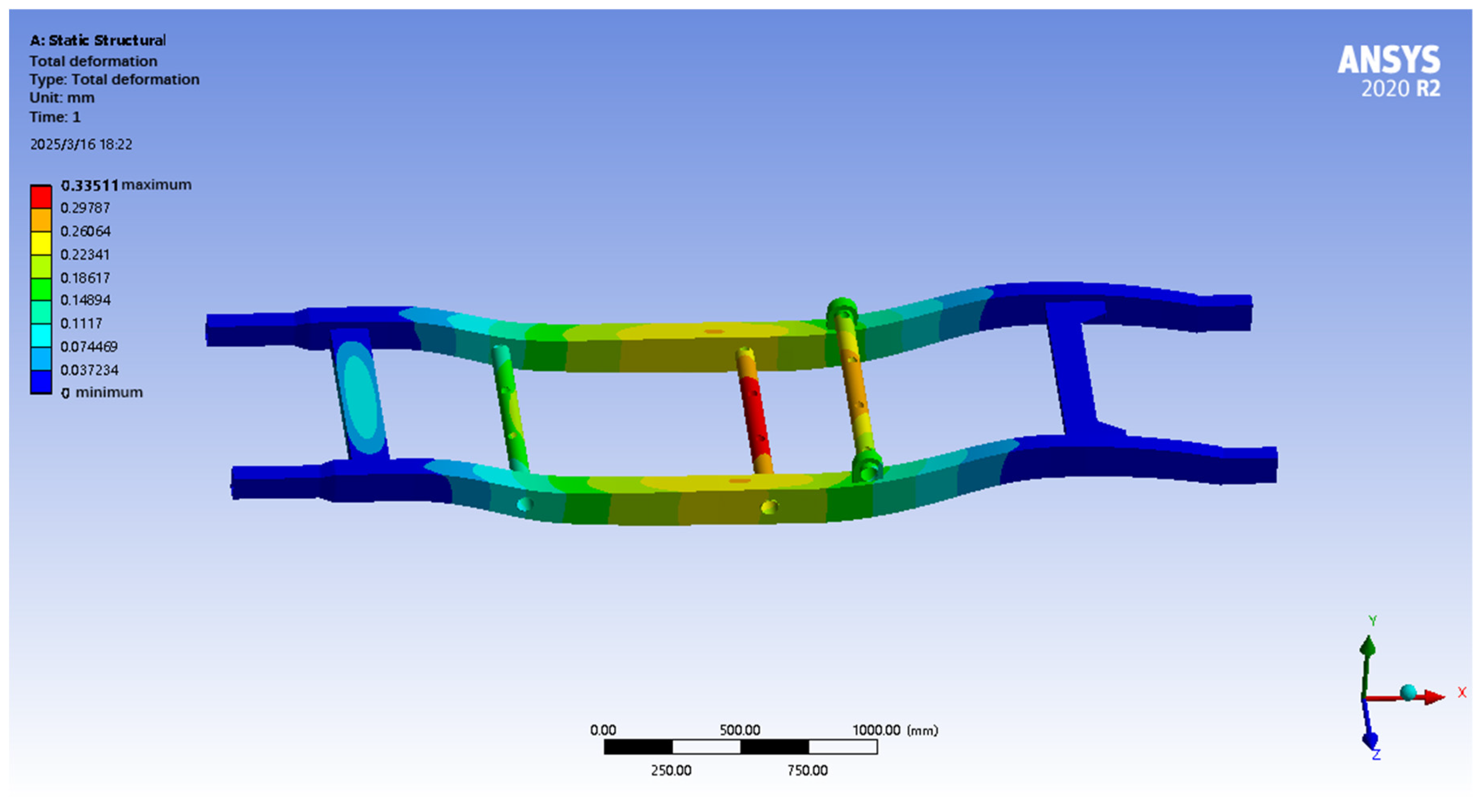
Solving the calculation under the full-load bending condition, the results of the displacement and equivalent force maps of the pure electric SUV frame simulation analysis are shown in
Figure 6 and
Figure 7.
After finite element analysis, the maximum total deformation of the frame under full-load bending condition is 0.33 mm, and the maximum equivalent stress is 101.65 MPa. The deformation map shows that the deformation mainly occurs in the bending parts of the longitudinal beams and crossbeams, which is consistent with the actual situation. The maximum equivalent force of the frame is 101.65 MPa, which is lower than the yield strength of the selected high-strength low-alloy steel, indicating that the frame will not undergo plastic deformation and has sufficient strength reserves. The maximum equivalent stress also appeared near the mounting position of the suspension, and the stress distribution is more uniform, without obvious stress concentration. According to the maximum equivalent force and the yield strength of the material, the safety coefficient of the frame is calculated to be about 3.39, which is much larger than the usual requirement of 1.5, indicating that the frame has high safety and reliability and is able to withstand the load under the full-load bending condition. The comprehensive analysis results show that the strength and stiffness of the frame meet the design requirements under full-load bending condition, which has good safety and reliability, and the next step can be considered to optimize the design of the frame. Based on the material yield strength (Q345 steel: 345 MPa) and maximum equivalent stress (101.65 MPa), the safety factor for the vehicle frame is calculated as 3.39 (345/101.65). This value is significantly higher than the minimum safety factor of 1.5, compliant with China’s national safety standards for electric vehicles and also meets the commercial vehicle chassis design standard (recommended ≥ 2.0), indicating that the structural safety margin is sufficient under bending conditions [
34].
3.5.2. Full-Load Braking Conditions for Load-Bearing Chassis
The full-load braking condition is the condition when the vehicle is under full load for emergency braking. In this typical condition, the frame may be subjected to large longitudinal loads due to inertial forces, especially near the front suspension mounting points, which are subjected to large braking forces. Therefore, it is crucial to analyze the strength and stiffness performance of the frame under full-load braking conditions to be able to assess the safety and reliability of the frame during emergency braking. The calculation is shown in Equation (5):
: Chassis load under full braking conditions.
: Dynamic load coefficient under full-load braking conditions, taken as .
: Braking acceleration, taken as 8 m/s2.
Setting constraints: In order to simulate the real force state of the frame under braking conditions, reasonable constraints need to be imposed in the finite element model. Similar to the full-load bending condition, this study still applies displacement constraints at the four suspension mounting points of the frame, i.e., constraining the translational degrees of freedom in the X, Y and Z directions, as shown in
Figure 8.
Setting loads: In the full-load braking condition, the frame is mainly subjected to inertial loads caused by braking force, resulting in the longitudinal and transverse beams being subjected to transverse forces. The calculation in Equation (5) above shows that a transverse force of 17,640 N is applied to the longitudinal beam to simulate the longitudinal inertia effect, and a transverse force of 3150 N is applied to the transverse beam to reflect the transverse force. This load application method can effectively simulate the force state of the frame during emergency braking and provide a basis for finite element analysis to evaluate whether the strength and stiffness of the frame meet the design requirements.
By solving the calculation, the results of the displacement cloud and equivalent force cloud of the simulation analysis of the pure electric SUV frame are known under full-load braking conditions, and they are shown in
Figure 9 and
Figure 10.
After finite element analysis, under full-load braking condition, the maximum total deformation of the frame is only 0.05 mm, which shows excellent stiffness, and the deformation is mainly concentrated in the steel pipe supporting the rear wheels. The maximum equivalent stress is 15.30 MPa, which is much lower than the yield strength of the material, and the safety coefficient is as high as 22.55, indicating that the frame has a sufficient strength reserve and high safety margin. Although there is a certain amount of stress concentration in the rear wheel support steel tube, the overall stress level is low, and the structural design is safe and reliable, and local optimization can be considered to further improve the strength or reduce the weight appropriately under the premise of ensuring safety. The maximum equivalent stress of the chassis is only 15.30 MPa, corresponding to a safety factor of 22.55 (345/15.30), Meets structural strength standards for pure electric vehiclestructural strength standard for pure electric vehicles, a safety factor of >5 under braking conditions is considered reliable. The current design has an extremely high safety margin [
35].
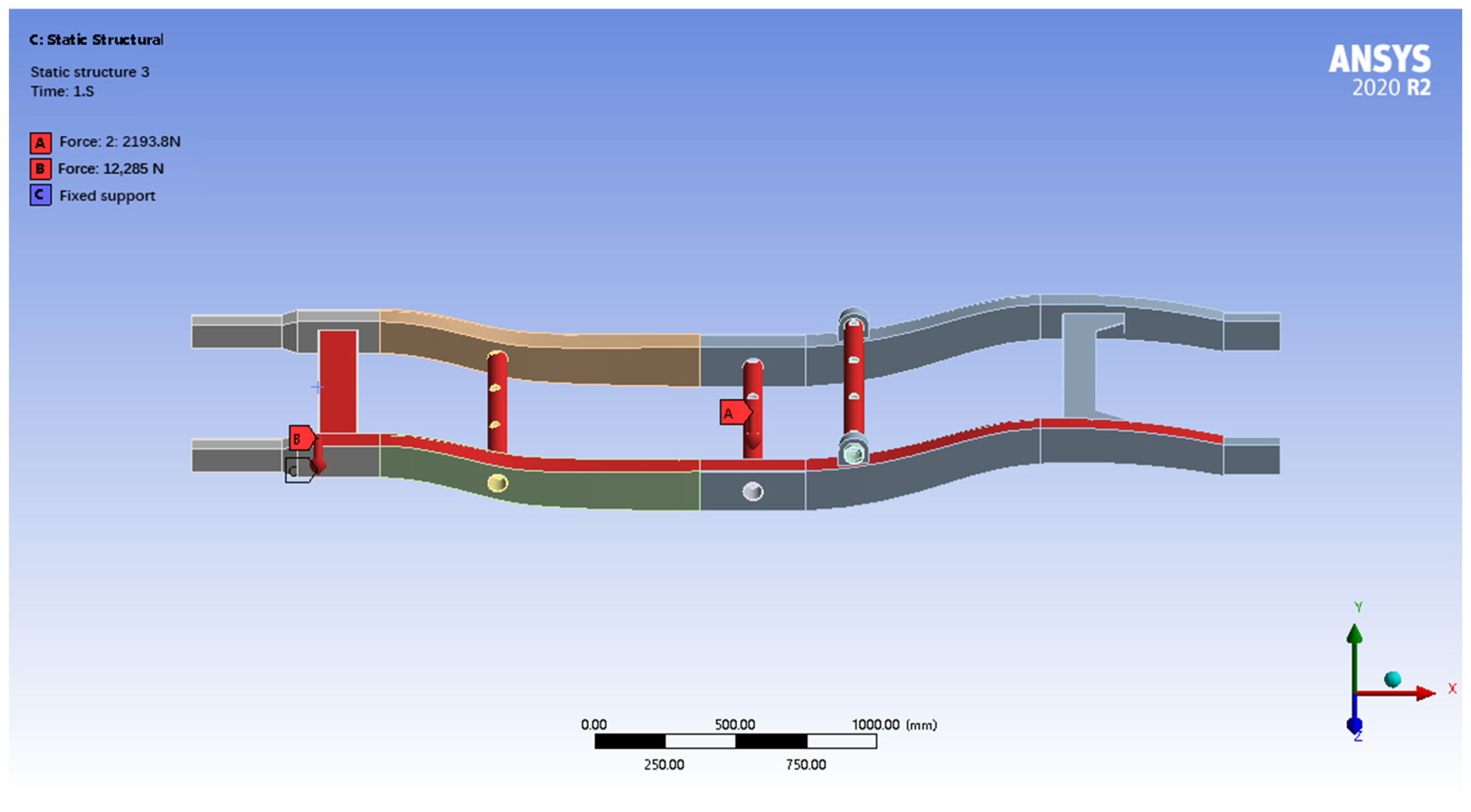
3.5.3. Full-Load Turning Conditions for Load-Bearing Chassis
Full-load turning condition refers to the condition when the vehicle is fully loaded for turning and traveling. In this condition, the vehicle is subjected to centrifugal force, and the frame is subjected to lateral and torsional loads. Analyzing the strength and stiffness performance of the frame under full-load cornering conditions can evaluate the anti-swaying ability and structural stability of the frame during cornering to ensure the handling and driving safety of the vehicle. The load calculation is shown in Equation (6) below:
: Chassis load (N) under full-load turning conditions;
: Dynamic load coefficient under full-load turning conditions (take);
: Centripetal acceleration when turning (taken as 4.5 m/s2).
Setting constraints: In order to simulate the real force state of the frame under braking conditions, reasonable constraints need to be imposed in the finite element model. Similar to the previous constraint setting, this study still imposes displacement constraints at the four suspension mounting points of the frame; i.e., the translational degrees of freedom in the X, Y and Z directions are constrained, as shown in
Figure 11.
Setting loads: under the full-load turning condition, the frame is mainly subjected to centrifugal force. To simulate this condition, the total centrifugal force is assigned to the longitudinal and transverse beams. Using Equation (6), a lateral force of 12,285 N is applied to the longitudinal beam, and a lateral force of 2193.75 N is applied to the transverse beam. These lateral forces are directed towards the center of the turn to simulate the centrifugal force acting on the vehicle during the turn.
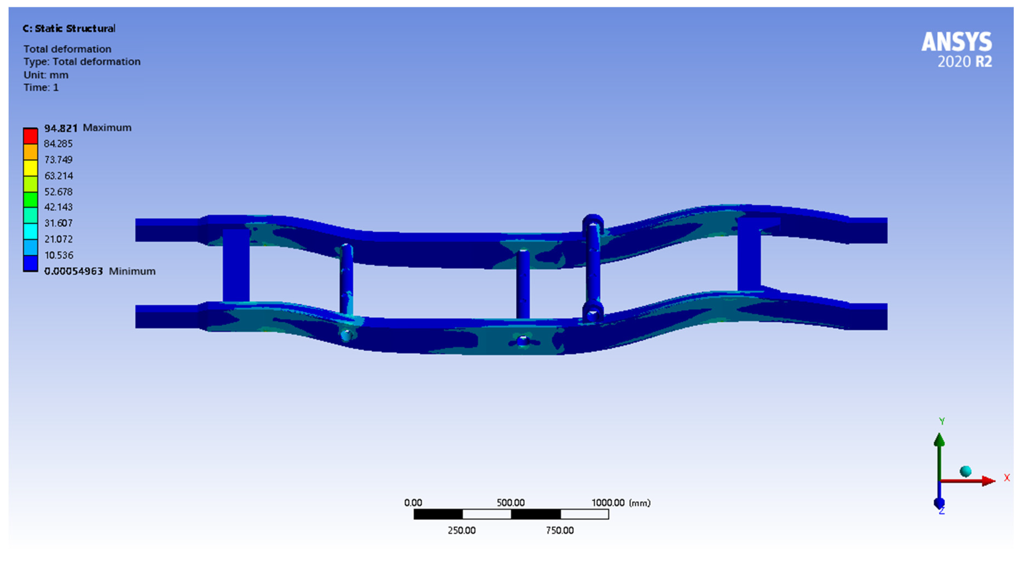
By solving the calculation, the results of the displacement and equivalent force maps of the pure electric SUV frame simulation analysis are known under the full-load turning conditions and are shown in
Figure 12 and
Figure 13.
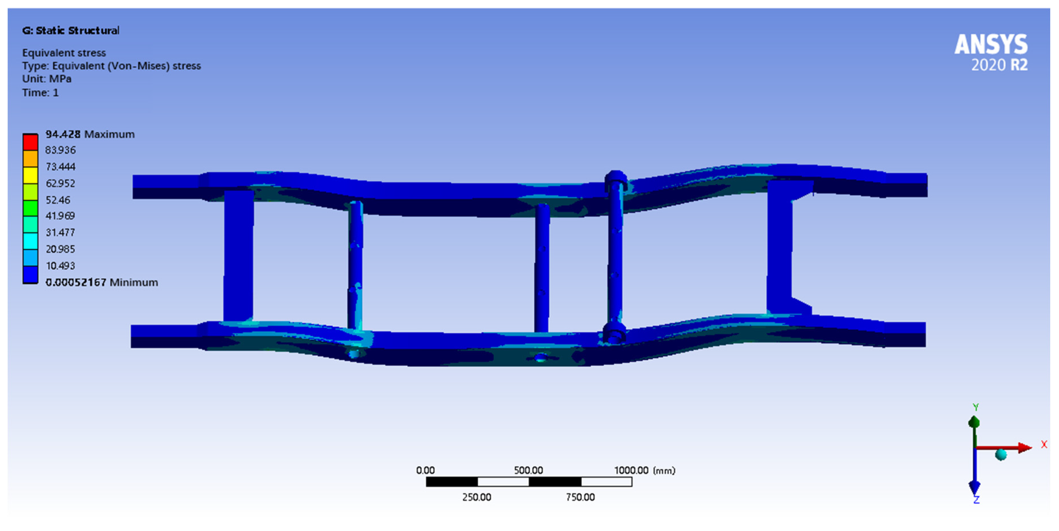
After finite element analysis under full-load turning conditions, the maximum total deformation of the frame is only 0.67 mm, which meets the stiffness requirement, and the deformation is mainly concentrated in the middle of the longitudinal beam on the stress side. The maximum equivalent stress is 94.82 MPa, which is much lower than the yield strength of 345 MPa, indicating that the frame has a sufficient strength reserve and high safety margin. Although there is a certain amount of stress concentration in the middle part of the longitudinal beam on the stressed side, the overall stress level is low, and the structural design is safe and reliable, and it can be considered to further improve strength by local optimization or by reducing the weight appropriately under the premise of ensuring safety. The safety factor at the maximum equivalent stress of 94.82 MPa is 3.64 (345/94.82), meet industry standards for vehicle rollover stability [
36]. Based on the analysis results of three typical operating conditions, the summary of the chassis static performance is shown in
Table 3.
5. Lightweight Optimization and Analysis of SUV Frames Based on Symmetry Preservation
As the core load-carrying component of an automobile, the frame has a high mass ratio, which directly affects the energy consumption, dynamics and range of the whole vehicle (especially for pure electric SUVs). Therefore, frame lightweighting is one of the key paths to realizing the energy efficiency improvement of electric vehicles. Currently, the mainstream lightweight strategy includes the use of lightweight and high-strength materials, the application of advanced manufacturing processes and the implementation of structural optimization design.
In view of the inherent left–right symmetrical structural characteristics of the load-bearing frame (about the longitudinal center plane of the vehicle), this symmetrical design is the basis for ensuring the stability of the vehicle’s driving, the balance of handling and the reasonableness of the load distribution. Based on the results of the previous finite element analysis, this paper chooses overall material replacement as the lightweight optimization scheme. The core advantage of this scheme is that it strictly maintains the original geometric and topological symmetry of the frame and only changes the material properties (density, modulus, strength), thus avoiding the unknown dynamic response or local stress concentration problems that may be introduced due to structural asymmetry changes to the maximum extent, and ensuring the controllability of the optimization process and the predictability of the results.
The specific material lightweight optimization implementation process is as follows:
- (1)
In the finite element software, the original frame model material is uniformly replaced by the target lightweight material.
- (2)
Under the premise of maintaining the original symmetric boundary conditions and symmetric/asymmetric loading conditions, the optimized frame is subjected to static analysis to check the stress distribution, maximum deformation and safety factors.
- (3)
A modal analysis of the optimized frame is conducted to extract the intrinsic frequencies and vibration patterns, paying special attention to whether the frequency changes and vibration pattern characteristics of the symmetric modes (e.g., first-order bending) and anti-symmetric modes (e.g., second-order torsion) are well maintained, and to assess the risk of resonance.
- (4)
The static and dynamic performance indexes (strength, stiffness, mode frequency, vibration mode symmetry) and mass of the frame before and after optimization are comprehensively compared to determine the feasibility and superiority of the lightweighting scheme.
5.1. Development of Lightweight Optimization Solutions Considering Structural Symmetry
In order to realize the lightweighting of the frame structure and reduce the material costs under the premise of guaranteeing performance, this paper adopts the replacement method for lightweight optimization. According to the force characteristics of different parts of the load-bearing frame of the pure electric SUV, QT450 ductile iron with a higher strength-to-mass ratio is selected to replace the original material in order to enhance the structural performance of the frame and achieve the lightweight goal at the same time. The material properties are shown in
Table 4 and
Table 5.
5.2. Optimization of Finite Element Analysis
5.2.1. Static Analysis Verification of the Optimized Chassis Under Symmetrical/Asymmetrical Conditions
The optimized pure electric SUV load-bearing frame uses the QT450 material, and static analysis is carried out based on the same load and boundary conditions as before optimization. The mechanical properties of the frame are evaluated under the typical working conditions of full-load bending, full-load braking and full-load cornering, focusing on the equivalent force distribution, maximum deformation and safety coefficient of the optimized frame, with particular attention paid to the structural response of the key stress parts, in order to verify that its strength and stiffness meet the design requirements under the ultimate load conditions.
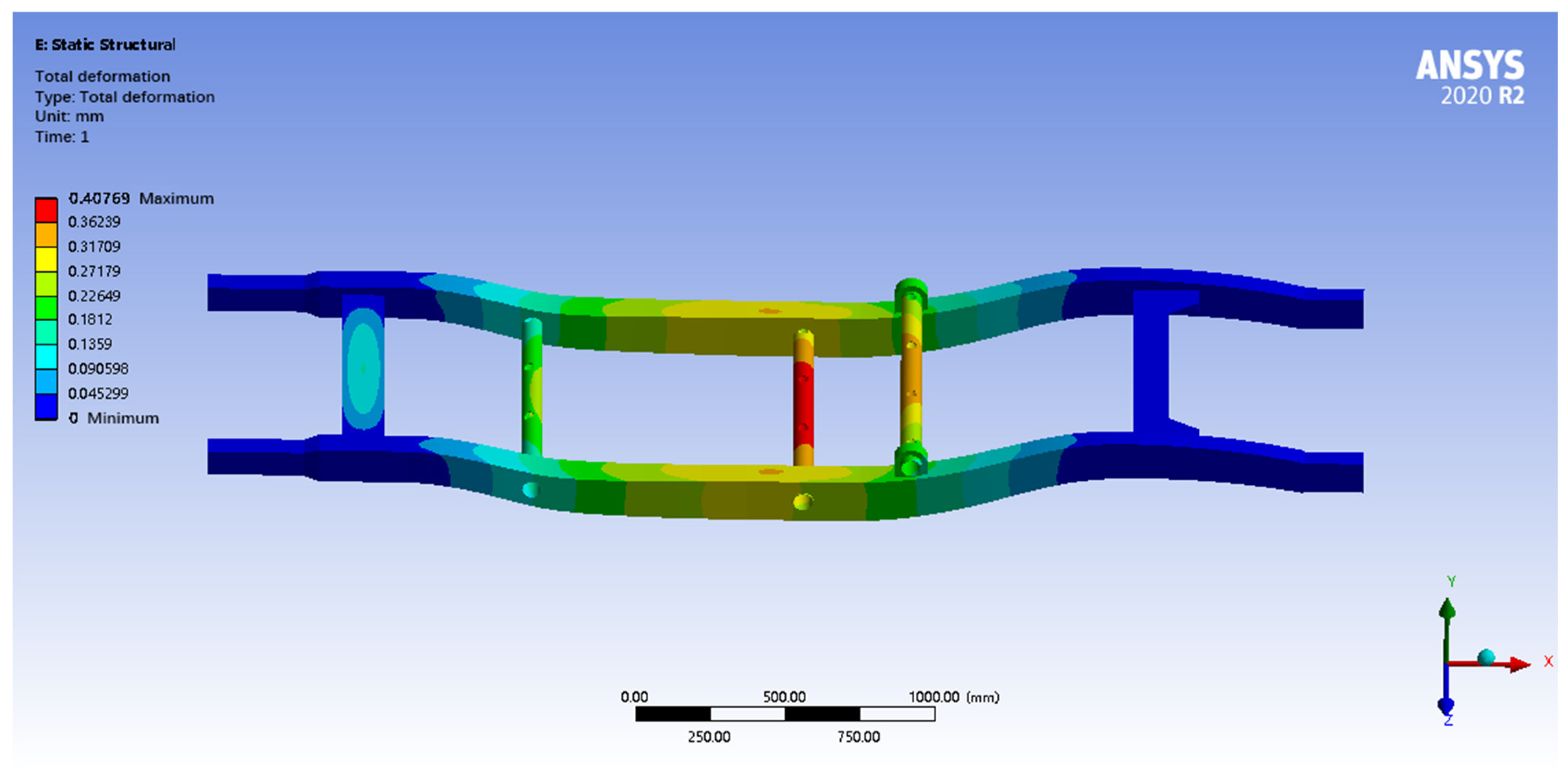
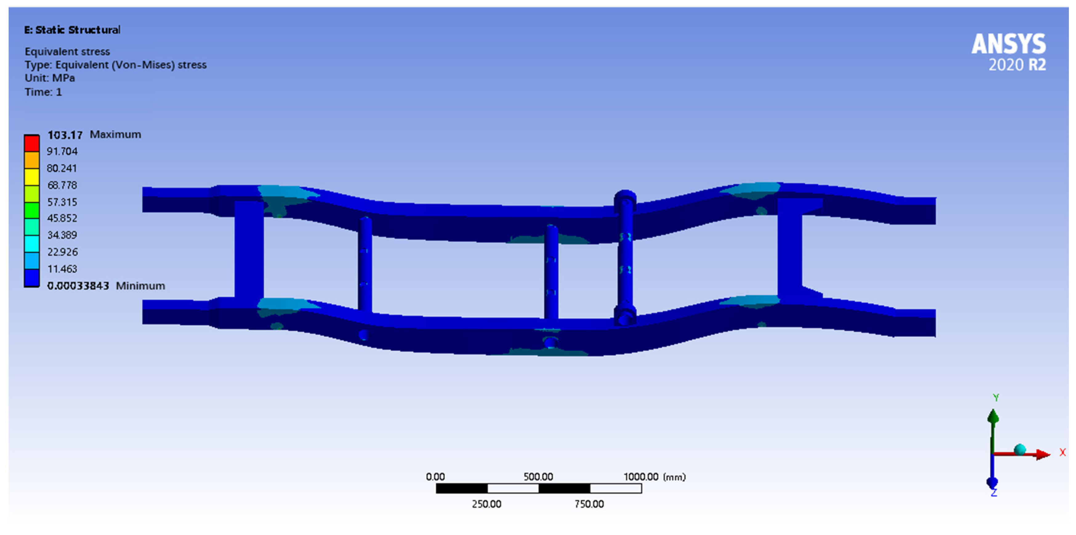
After finite element analysis, the maximum total deformation of the optimized frame under full-load bending conditions is 0.4 mm, and the maximum equivalent force is 103.17 MPa. The deformation cloud diagram shows that the deformation mainly occurs in the bending parts of the longitudinal beams and crossbeams, which is in line with the actual situation, as shown in
Figure 15 and
Figure 16. The maximum equivalent force of the frame is 103.17 MPa, which is lower than the yield strength of the selected high-strength low-alloy steel, indicating that the frame will not undergo plastic deformation and has a sufficient strength reserve. The maximum equivalent stress also occurs near the suspension mounting position, and the stress distribution is relatively uniform, with no obvious stress concentration. According to the maximum equivalent force and the yield strength of the material, the safety coefficient of the frame is calculated to be about 3.3, which is much larger than the usual requirement of 1.5, indicating that the frame has high safety and reliability and is able to withstand the load under full-load bending conditions. The comprehensive analysis results show that the strength and stiffness of the frame meet the design requirements under full-load bending conditions and have good safety and reliability.
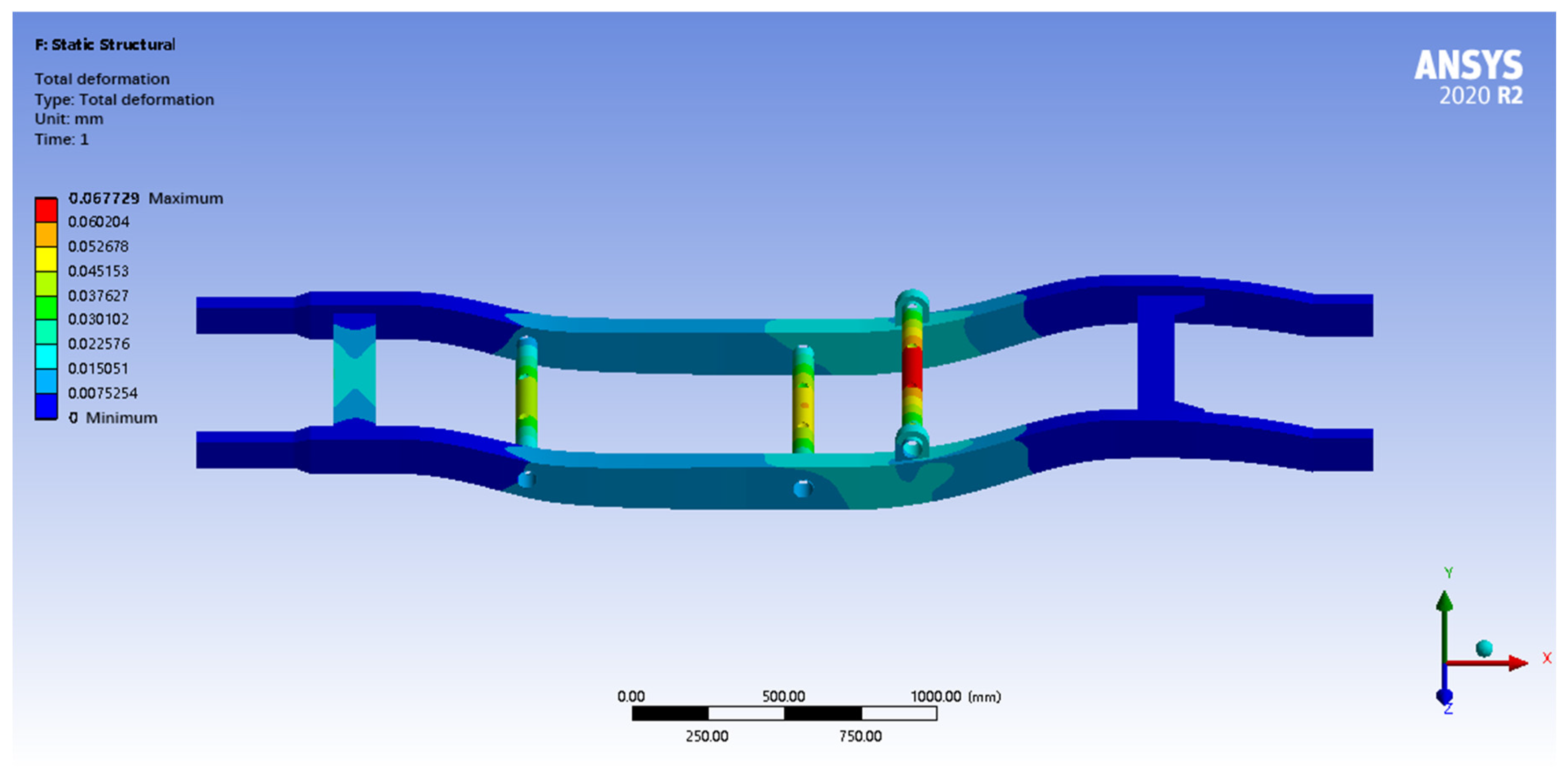
After finite element analysis (FEA) calculations, under full-load braking conditions, the FEA results show that the maximum total deformation of the optimized frame is only 0.06 mm, which shows excellent stiffness, and the deformation is mainly concentrated in the rear wheel support steel tube. The maximum equivalent stress is 15.31 MPa, which is much lower than the yield strength of the material, and the safety coefficient is as high as 22.48, indicating that the frame has a sufficient strength reserve and high safety margin. Although there is a certain stress concentration in the rear wheel support steel tube, the overall stress level is low, and the structural design is safe and reliable, as shown in
Figure 17 and
Figure 18.
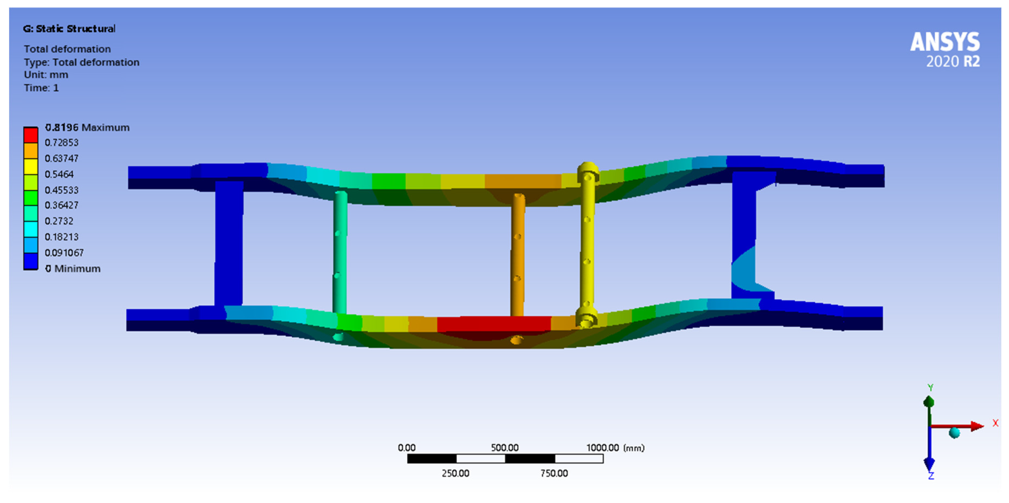
After finite element analysis calculations under full-load turning conditions, the finite element analysis results show that the maximum total deformation of the optimized frame is only 0.81 mm, which meets the stiffness requirement, and the deformation is mainly concentrated in the middle of the longitudinal beam of the stressed side. The maximum equivalent stress is 94.42 MPa, which is much lower than the yield strength of 310 MPa, indicating that the frame has a sufficient strength reserve and high safety margin. Although there is a certain stress concentration in the middle part of the longitudinal beam on the stressed side, the overall stress level is low, and the structural design is safe and reliable, as shown in
Figure 19 and
Figure 20.
5.2.2. Modal Characteristic Analysis of the Optimized Symmetrical Frame Structure
On the basis of evaluating the static mechanical performance of the optimized frame structure, modal analysis is required to ensure the stability and comfort of the frame in actual operation. Based on the same load and boundary conditions as those before optimization, modal analysis is carried out to evaluate its dynamic performance and verify that the optimized frame can operate safely and reliably, the first six natural frequencies of the optimized frame are shown in
Table 6.
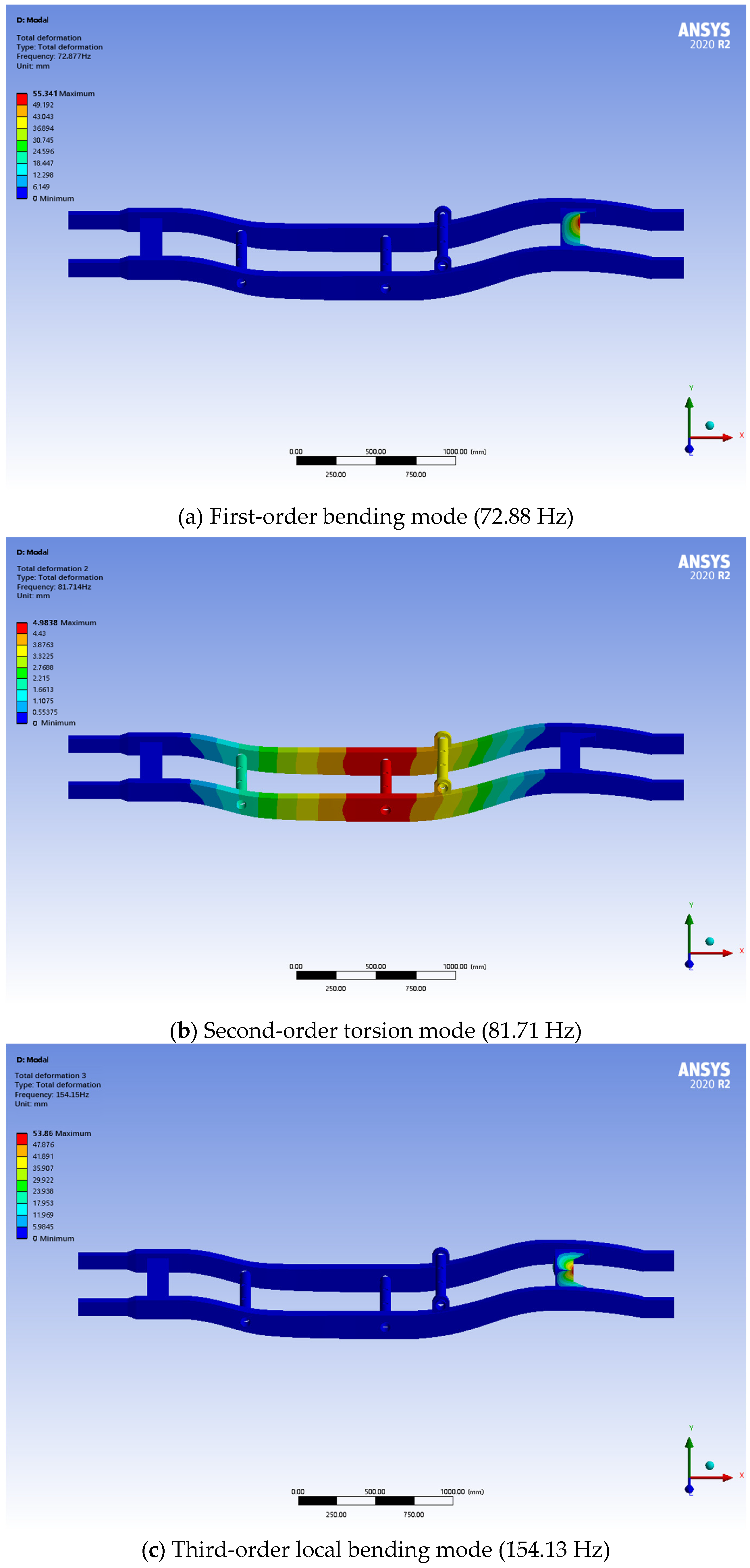
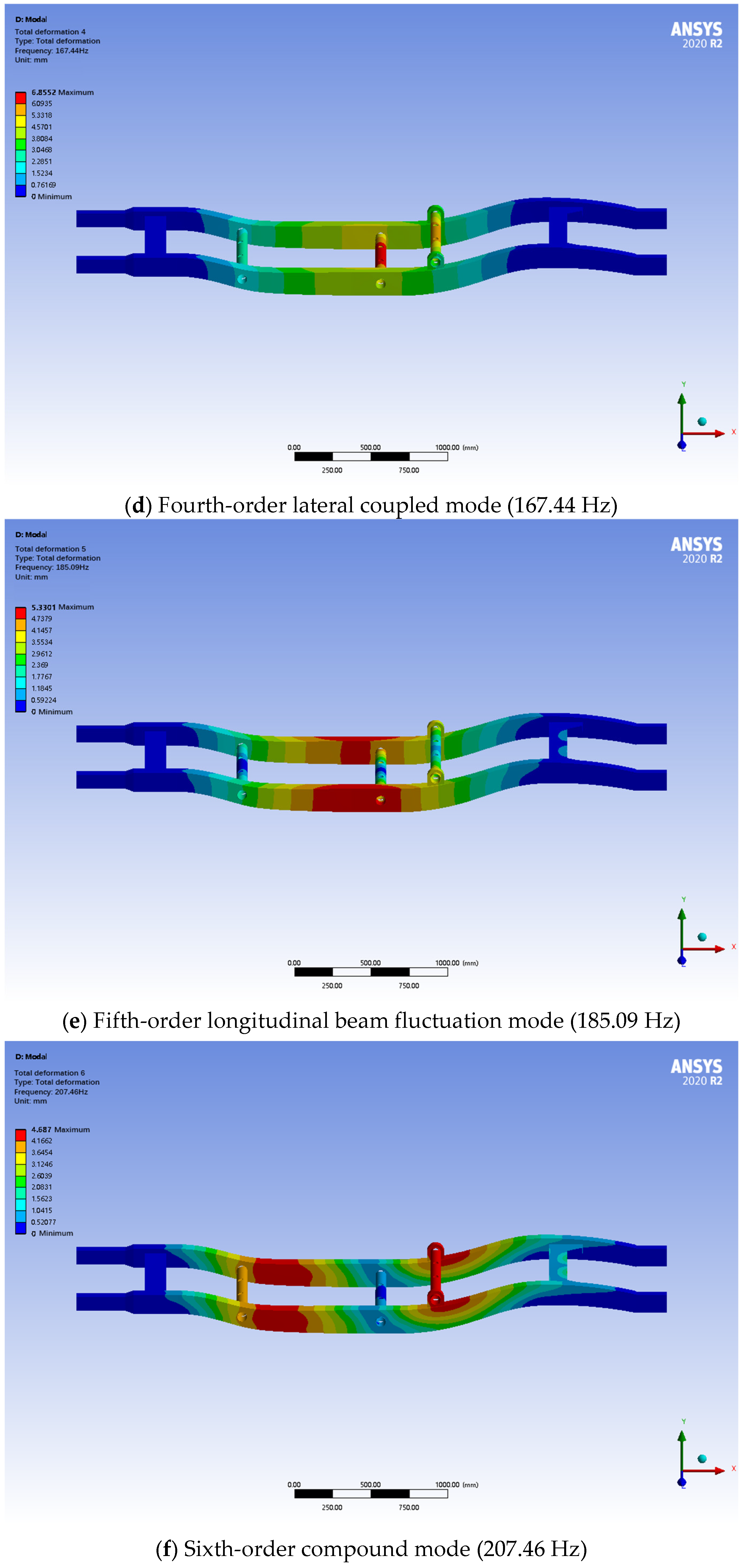
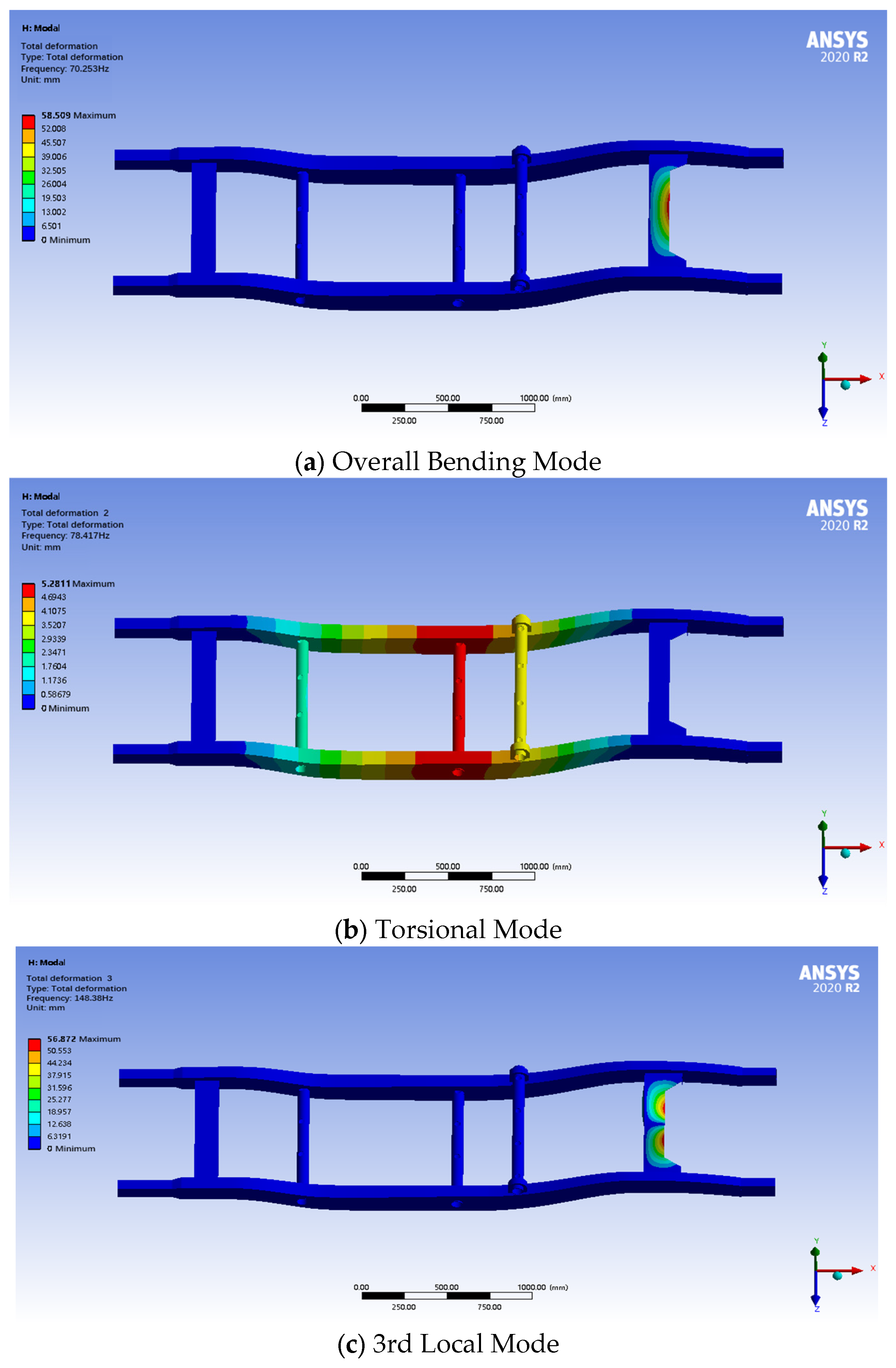
Through the results of modal analysis, it can be learned that the first-order modal frequency of the frame is 70.25 Hz, which is mainly manifested as the overall bending vibration. The second-order modal frequency is 78.41 Hz, which mainly shows that the frame has certain torsional characteristics. The third- to sixth-order modal frequencies are higher, respectively, at 148.38 Hz, 160.76 Hz, 177.72 Hz and 199.10 Hz, which mainly reflect the vibration characteristics of the local structure, as shown in
Figure 21. According to the results of the modal analysis, the first-order intrinsic frequency of the frame is higher than the common road excitation frequency in the range of 0–50 Hz, and so under normal driving conditions and through the material optimization of the frame, the coupling phenomenon did not occur; the first six orders of the modal analysis are with the external excitation of the larger gap, so the frame will not produce the resonance phenomenon, and the frame’s dynamic performance is good.
5.2.3. Assessment of Lightweight Optimization Effects and Symmetry Preservation
This study focuses on three typical static conditions (full-load bending, braking and turning) to evaluate the basic performance of the vehicle frame. Dynamic and fatigue loads have been included in the research plan as subsequent priorities. Dynamic load coverage: Static conditions are equivalent to peak loads through dynamic coefficients (braking condition , turning condition ), combined with a design margin of safety factor > 3.0, to cover conventional dynamic impacts. Fatigue analysis plan: Based on the optimized model in this paper, real-world road profiles (off-road sections at the Xiangfan Test Track) will be imported. Combined with the S-N curve of QT450 material, fatigue life prediction will be conducted. Extreme condition supplement: For special SUV usage scenarios (e.g., off-road impacts), multi-body dynamic co-simulation (Adams 2024/Ansys 2024 R1) has been planned to simulate the transient response under a 30 km/h bump crossing condition.
From the results of the above static analysis, it is concluded that the optimized frame is slightly lower in stiffness and strength than before optimization, but its stiffness and strength fully meet the requirements of this problem and can be ignored. On this basis, the weight reduction before and after lightweighting of the model is compared. The quality assessment tool that comes with SolidWorks software 2019 is used to make a precise quality comparison analysis of the frame model before and after optimization. The results show that the mass of the original frame model with high-strength, low-alloy steel is 81 kg, while the mass of the optimized model with the QT235 material is significantly reduced to 68 kg. A comparison of key performance parameters is shown in
Table 7.
The lightweight design did not significantly affect the mechanical properties (stress increase ≤ 1.5%, frequency decrease ≤ 3.6%), proving the effectiveness of the QT450 material replacement plan. The optimization not only successfully achieves a weight reduction of 13 kg, which is 16%, but also proves that the material replacement scheme can effectively reduce the mass of the frame under the premise of meeting the requirements of strength and stiffness in the previous analysis. This fully demonstrates that through reasonable material selection and optimized design, the weight level of the frame can be significantly improved without sacrificing structural performance, which provides an effective reference for acceleration performance, energy consumption and range extension of the subsequent vehicle.


