1. Introduction
The mechanical characterization of architected metamaterials is a central aspect of their development, especially as applications increasingly demand a predictive understanding of elastic and plastic behavior under complex loading conditions. While metamaterials are typically defined by their geometry-induced mechanical response, recent research has shifted the focus to systematically quantifying their effective stiffness, strength, failure modes, and post-yield behavior using a combination of experimental and computational tools. In this context, mechanical testing, finite element simulations, and data-driven inverse methods play complementary roles in both understanding and optimizing the mechanical performance of these architected systems.
A fundamental challenge lies in predicting the effective elastic response of periodic or stochastic lattices based on their microstructural topology. This has prompted the use of inverse design approaches that target specific elastic moduli or stress–strain behaviors. For example, Cao et al. [
1] propose a deep operator learning framework for reconstructing the nonlinear mechanical responses of disordered metamaterials from limited microstructural input. Park et al. [
2] extend this concept to dynamic regimes, using generative modeling to isolate the impact of geometry on both stiffness and vibration properties of 3D chiral architectures.
The ultraelastic constitutive law has been addressed by [
3], which performed the calculation of the average strain–stress curve using a step-by-step analysis and 3D finite elements. In [
4,
5], it is proposed that the stress limit is calculated as the collapse load resulting from a uniform average stress. The main differences between the two approaches consist of using a one-dimensional finite element instead of a three-dimensional hexahedral element and directly calculating the collapse stress limit through the lower bound method. Many works [
6,
7] dealing with limit analysis implemented in the finite element environment use an ad hoc iterative procedure. The proposal enables the straightforward calculation of the limit load.
Computational modeling techniques, particularly those based on finite element analysis (FEA), have become indispensable for understanding stress distribution, local instabilities, and failure mechanisms at both the unit cell and continuum scales. Fong et al. [
8] develop a topology optimization framework to design metamaterials with tunable elastic moduli, leveraging commercial FEA tools to account for boundary conditions and load paths. In a related work [
9], the same authors explore thermal–mechanical interactions, showing how material layout affects the coupling between elasticity and conductivity.
Beyond elasticity, understanding plasticity and post-yield deformation is becoming increasingly relevant for applications that require energy absorption, durability, or resilience under cyclic loading. Song et al. [
10] investigate the mechanical response of hierarchical architectures under compressive loading, revealing plastic strain localization and improved energy dissipation due to geometric hierarchy. Experimental methods play a key role in capturing such effects, especially when combined with high-resolution strain field measurements and fracture pattern analysis.
Manufacturing constraints and real-world imperfections introduce additional variability, making stochastic analysis and statistical homogenization necessary for robust design. Kayacan et al. [
11] analyze the mechanical response of metal-based metamaterials produced by hybrid additive manufacturing, noting deviations between nominal and measured yield behavior. Similarly, Álvarez-Trejo et al. [
12] provide a comprehensive overview of curved-element topologies, emphasizing the influence of nonlinearity and stress concentration under large deformations.
Plasticity is also central in origami- and kirigami-based metamaterials, where localized folding can act as a design mechanism or as a failure mode. Bagheri et al. [
13] study an origami-inspired deformable architecture, characterizing its large strain behavior under repeated loading, with implications for bioengineering scaffolds. At the multiscale level, Li et al. [
14] conduct experimental testing to quantify nonlinear elasticity and plasticity in architected materials, combining mechanical loading with in situ measurements and high-fidelity simulations.
A growing area of interest is the integration of mechanical modeling with active or programmable elements, where plastic deformation may be either avoided or deliberately induced. Zhang et al. [
15] present a reprogrammable mechanical system based on embedded actuators, while Lu et al. [
16] review construction principles for active architectures capable of adapting their stiffness or deformation mode.
Finally, the role of mechanical characterization in functional applications is addressed by Kazim et al. [
17], who emphasize the need for precise control over the elastic regime in wearable and implantable devices. Zhang et al. [
18] complement this view by reviewing metamaterials used in sensors and actuators, where elastic precision and fatigue behavior are critical. This body of research reflects a broader trend toward high-fidelity characterization of architected materials through the coupling of simulation and experiment, topology optimization, and nonlinear mechanical modeling. Emphasis is increasingly placed on quantifying material response beyond the linear elastic regime, with the goal of enabling robust, application-ready metamaterials with predictable mechanical behavior under service conditions.
This study aims to investigate the mechanical behavior of structured metamaterials by characterizing both their elastic and plastic response at the microscale. The primary objective is to establish a robust computational procedure for evaluating the ultimate strength of metamaterials modeled as periodic microstructured continua. This type of structure represents the basic cell of complex systems, characterized by periodic repetition. They are of particular interest in additive manufacturing for constructing performance-based objects [
3,
19,
20,
21,
22].
In the elastic regime, the analysis focuses on an octet truss lattice, whose mechanical response is simulated under virtual loading conditions using the commercial finite element software Ansys (version 19.1). The resulting stiffness matrix is used to verify isotropy via Zener’s criterion, identifying specific density configurations that ensure isotropic behavior.
To extend the investigation into the plastic domain, the study uses a novel finite element limit analysis approach developed by the authors [
4]. This method is grounded in the lower bound theorem [
23,
24,
25,
26] and utilizes the self-equilibrated stress fields, whose map is related to discrete nodal parameters that form the basis of the admissible stress. Among the loads in equilibrium with admissible stress, one must search for the upper bound that is the collapse load.
2. Homogenization and Limit Analysis for RVEs of Structured Metamaterials
This work addresses two primary research focuses. The first concerns elastic homogenization and the assessment of isotropy in selected well-known geometries of structured metamaterial representative volume elements (RVEs). Specifically, the study analyzes two typical cubic elements: first, a truss configuration combining body-centered cubic (BCC) and pure cubic (PC) elements, referred to as the isotropic truss, and second, a cubic representation of a star-like lattice system. The second focus lies in the application of limit analysis to these elementary cells, with the objective of evaluating the ultimate mechanical behavior of the homogenized material starting from the limit load of the RVE.
This section provides a concise overview of the methodology adopted to evaluate the elastic properties of the metamaterial structures. The proposed approach draws inspiration from the work of Lakes [
27], who established theoretical estimates for elastically isotropic lattices based on stretching-dominated behavior at the mesoscopic scale, and from Messner [
28], who explored isotropic truss lattices through topology optimization techniques. Building on these studies, we define analytical conditions for lattice topologies that result in macroscale elastic isotropy.
The analysis is based on the definition of a unit cell, which is intended as the substructure whose periodic repetition and translation—without rotation—form extended lattice architectures. The study focuses on metamaterials composed of linear elastic perfectly plastic constituent material. Although the constituent material of the RVEs possesses an isotropic standard constitutive law, when it is subjected to elementary periodic strain fields, the resulting stress at the macroscale may not correspond to that of an isotropic continuum. The effective elastic and strength characteristics are strongly influenced by the spatial arrangement and relative stiffness of the lattice members, particularly in configurations such as the body-centered cubic and pure cubic cells. Depending on the orientation and geometry of these elements, the homogenized elasticity tensor may exhibit either isotropic or anisotropic behavior in the elastic range; analogous results have been found in the ultraelastic range.
As such, the mechanical response of these systems is primarily governed by their micro- or nano-architecture, together with the intrinsic properties of the base material.
2.1. Homogenized Material Elastic Constitutive Law
To assess the elastic behavior of the structures, finite element analyses were conducted by applying uniform macroscopic strain fields to representative unit cells, utilizing periodic boundary conditions to ensure mechanical compatibility. The RVE is assumed to be a framed structure made of beams with flexural and axial degrees of freedom connected at nodes. The structure behaves in the same way if the beam element is substituted by a link, i.e., a pure axial rod.
These low-density architected metamaterials exhibit mechanical advantages—most notably, enhanced compressibility and high energy absorption—which are primarily governed by their mesoscale geometry. This reinforces the central premise that the mechanical response of metamaterials is driven more by structural design than by the intrinsic material properties of the base constituent.
The unit cell has been described using one-dimensional elements that exhibit both pure extensional and flexural behavior. It has been observed that there are substantial coincidences between the two models when they are used to calculate the elastic response. It can be seen that the Zener coefficient in
Table 1, referred to as the link or beam, is almost the same. In the following table the isotropic configuration is highlighted.
The homogenized material is described by the average fields of continuum mechanics, namely a displacement vector field
, the associated strain tensor field
, and the corresponding stress tensor field
,
where the operator
is the elastic fourth-order tensor of the homogenized continuous material. In the following application with finite elements, the second-order and fourth-order tensors are reformulated, assuming the index contraction according to Voigt notation, so that the strain and stress become first-order six-component vectors, and the elastic tensor becomes a second-order six-by-six symmetrical matrix.
The RVE stress has been calculated using a prescribed elementary strain, specifically a unit strain belonging to the strain base, which has been applied to the framed structure, see
Figure 1, through simultaneous nodal displacements on each cube face. The average strain has been calculated considering
As a result of the structural calculation, nodal reaction forces give the homogenized stress as
where the sum is extended to all the nodes belonging to
th cube face having an area
. The six stress components corresponding to each strain unity vector form a column of the elastic matrix.
The prescribed displacements to obtain unit strain involve only the translational degree of freedom of nodes. The rotational degree of freedom does not correspond to the three-dimensional Cauchy continuum model and has been ignored. The symmetry class of the resulting elasticity matrix
defines the material’s anisotropy. In particular, a rather general strategy for classifying the anisotropy of ℂ is reported in the paper by Cowin and co-authors, building upon the works by Lord Kelvin [
29,
30,
31,
32]. The cubic symmetry of the RVE results in a cubic elastic tensor of the equivalent material, where the number of independent elastic constants is equal to three.
The elastic matrix in the Voigt notation for cubic material [
33] is
with the relationship between the constants
,
, and
.
In the present work, a preliminary simplified test has been considered to check the isotropy of the resulting homogenized material. Isotropic materials present a particular elastic matrix where only two independent constants, Lamé constants
and
, describe the constitutive law.
since the form of the isotropic matrix, the Zener ratio,
is equal to one for isotropic materials, and its deviation from unity can be assumed as a measure of the material isotropy [
34,
35]. The results of the numerical simulation confirmed that ℂ is composed of two three-by-three diagonal submatrices, with null three-by-three off-diagonal submatrices, and the lower diagonal submatrix reducing to a pure diagonal one.
2.2. Yield Limit Evaluation
The limit analysis has been used to evaluate the ultimate strength of the representative volume element of the lattice structure. A direct computational approach, based on the lower bound theorem presented in [
4], namely FELA (finite element limit analysis), has been used to evaluate both the collapse load multiplier and the limit domain of the homogenized material, starting from the lattice geometry and material characterization. The RVE has been subjected to nodal forces corresponding to elementary macrostresses through Equation (3). Using the lower bound method, the collapse value of nodal forces has been calculated, and the homogenized limit stress has been evaluated. The FELA method calculates the limit load as the upper bound of the applied load that satisfies the compatibility requirements, depending on the constituent material limit locus.
To clarify the ideas, a brief recap of the FELA procedure is provided below. The first step consists of finding the manifold to which the admissible stress must belong. The admissible stress within the structure is supposed to be the superimposition of the elastic response,
to the loads,
of the ideal elastic structure, and any self-equilibrated stress
that maps the multiplicity of balance equations operator
:
The explicit equilibrium of the RVE can be considered in two parts: the actual equation, which involves the actual stress, and the pure elastic equation, which involves the stress arising in an ideal material with an elastic constitutive law.
The admissibility of the stress is verified when the stress belongs to the interior of the elastic domain
, ensuring that no permanent strain
increases:
As can be seen from Equation (8),
plays a key role, and the effectiveness of the method requires describing the self-equilibrated stress manifold completely. The complete description of the
can be achieved by introducing a vector base of the self-equilibrated stress vector space. The FELA method enables the construction of such a vector base through nodal parameters, utilizing the same shape functions employed for the finite element description of displacement at the element level. The procedure is completely general and suitable for any element type and shape function family; however, in the proposed application, the structural model of the RVE is obtained using Bernoulli beam elements, and the self-equilibrated local stress reduces to ordinary element forces, say axial, shear forces,
N and
Si, and bending moment
Mi , along with the axis in the element cross-section plane. The shear force effects are ignored, so only axial stress and bending are considered as effective stress components. Analogously, only strain generalized components corresponding in energy to the effective stress have been considered, hence
The solution of the structure subjected to zero applied forces allows the definition of the self-equilibrated stress as a linear function of the nodal parameters describing the permanent strain at the element level and the displacements of constrained nodes, which are collected in the vector
δ. Direct formulation described in detail in [
4] allows for the construction of the linear operator
governing the correspondence with the generalized self-equilibrated stress
with
The elastic domain of the RVEs representing the compatibility constraints is an ellipsoid in three-dimensional space, having its axes spanning the limits
where the indexes,
and
, indicate the positive and negative yield limits of generalized stress along the direction in the element cross-section.
RVE natural boundary conditions are nodal forces applied to nodes belonging to one cubic face, acting along the outward normal to the face when the normal stress limit is calculated, and directed along one of the in-plane directions of the face when the shear limit is sought. Essential boundary conditions consist of periodic constraints on the displacement, which reproduce a repeatable, uniform stress state that extends throughout the entire solid.
The elastic solution has been calculated considering the RVE made of element beams, and the corresponding stress:
Considering load increasing through a scalar multiplier
, the following optimization program furnishes the collapse load multiplier,
:
The maximum force calculated in the program (6) corresponds to the yield stress, as per Equation (3), that is assumed to represent the point in the stress space where the elastic domain of the homogenized material intersects the stress axis.
This formulation avoids path-following iterative approaches and directly computes the stress limit as the supremum of the lower bound. The procedure has been applied to a lattice structure with different geometries to determine the collapse multipliers. The resulting intercept points define the axes of the limit locus, which has a six-dimensional hyper-ellipsoidal shape. It is essential to note that the limit stress domain is defined in the reference frame of the stress acting on the cubic element faces, known as the special stress space. The representation differs from the Haigh–Westergaard space representation, as it assumes that the stress direction influences the limit. In the special stress space, von Mises’ plasticity criterion gives the ratio of the limit normal stress to shear stress to be . The numerical experiments reported in the following section highlight that, depending on the ratio between the BCC and PC geometries, such a stress ratio is violated in many cases, indicating that limit isotropy is also violated.
3. Results
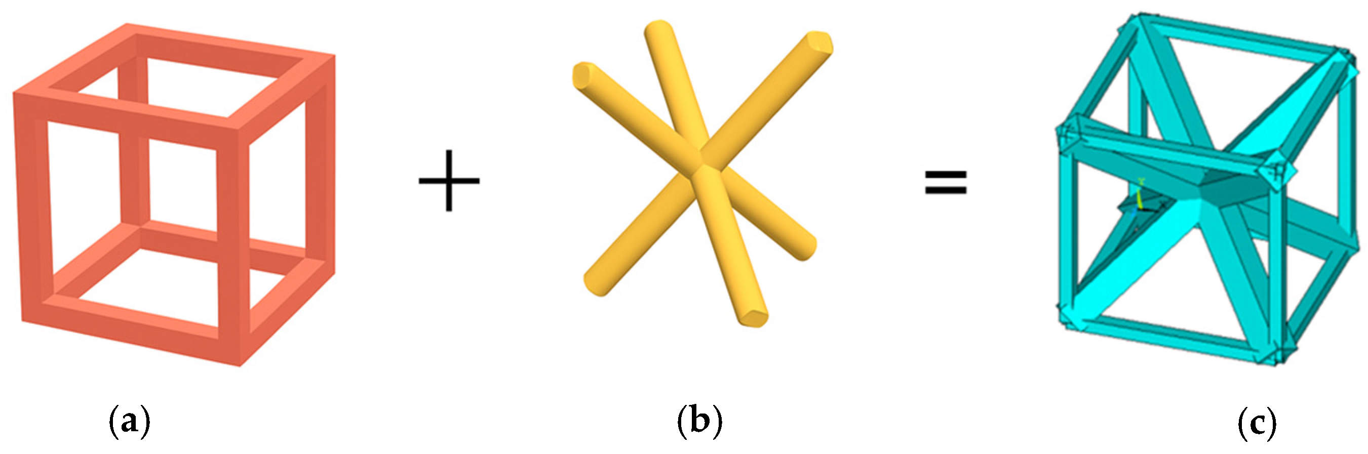
In this section, two representative lattice configurations are introduced to investigate both the elastic behavior and collapse strength of structured metamaterials: an isotropic truss made of a BCC and PC assembly and a three-dimensional Equivalent Star System (ESS). For each lattice structure, two main aspects are analyzed: the elastic response, evaluated through numerical homogenization, and the limit strength, assessed via numerical limit analysis, which leads to the definition of the associated limit domain.
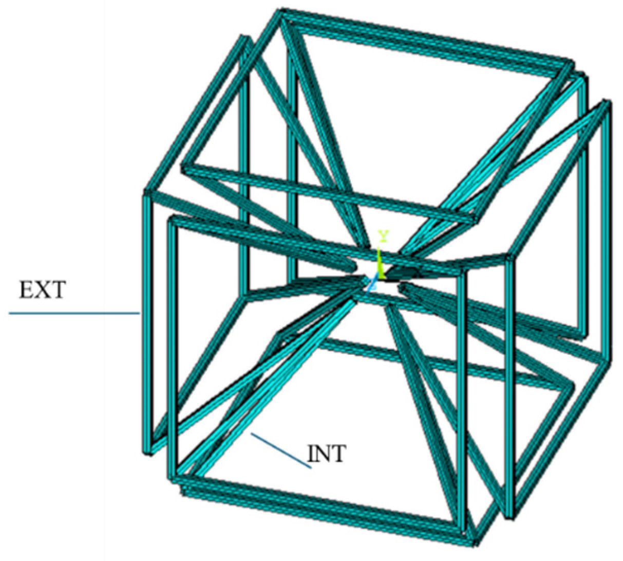
The Equivalent Star System (ESS) is a spatial lattice consisting of a central star-shaped core connected to a surrounding cubic frame.
This configuration exhibits auxetic behavior, which is investigated as a function of the cross-sectional ratio between the inner element and outer element beams. In this context, the inner members—inclined beams—are primarily axial deformation-dominated, while the outer cubic frame elements respond mainly through flexural deformation.
For the ESS case, an energy-based analysis is also performed to obtain suggestions on the prevailing deformation mechanism. By varying the cross-sectional ratio, the contributions of bending and axial strain energy are evaluated to qualitatively highlight that the structure behaves predominantly as a bending system, as observed in the energy ratio results. The relevance of flexural energy justifies the structure’s high rotational displacements, resulting in both auxetic and low stiffness effects.
3.1. The Isotropic Truss
The first case study examines a lattice configuration resulting from the combination of a body-centered cubic (BCC) geometry with a pure cubic (PC) arrangement, see
Figure 2.
In particular, for this configuration only, one-dimensional simulations with both BEAM and LINK elements were conducted to demonstrate that bending effects at the nodes are negligible [
4]. The consistency of the results across both element types confirms that the presence or absence of flexural behavior does not significantly influence the global response, thus validating the simplification.
The analysis also investigated various cross-sectional combinations between the components forming the BCC and PC structures. The objective was to assess the impact of sectional size on the isotropy of the lattice and to identify the optimal section ratio that minimizes anisotropy. The considered RVE dimensions are 5mm. The study thus evaluates how the geometric ratio between BCC and PC elements affects the effective isotropic behavior of the RVE, as shown in
Table 1. A first result confirmed by the numerical simulation is that the isotropy of the homogenized material does not depend on the dimensions of the element, but rather on the ratios between the relevant dimensions, defined as the ratio between the cross-sectional side
of the PC elements and the BCC elements and
, and on the element length.
Since the independence of the sought response from the absolute element size was ensured, the analyzed specimen was chosen because it is possible to print and test it using the laboratory equipment [
36].
The material behavior of the numerical test specimens was approximated using steel-like properties, with a Young’s modulus and a Poisson’s ratio .
Several geometric configurations were examined, each corresponding to a different
. Only the resulting elastic constants of the homogenized isotropic element are reported. It can be seen that the evaluated homogenized Young’s modulus
and Poisson ratio
are given by
and
The same cell was analyzed in the plastic regime using limit analysis to determine the yield stress under pure uniaxial loading and pure shear loading. The homogenized stress, obtained through Equation (3), corresponding to the stress level obtained by (15), gives the limit values along the special stress axis:
and
In a pure isotropic limit test of a specimen, the uniaxial tensile stress, assuming the material is isotropic at the limit, is used to calculate the pure shear limit using the von Mises yield criterion that furnishes
It can be seen that the limit shear stress obtained by homogenization is different from the ideal one since
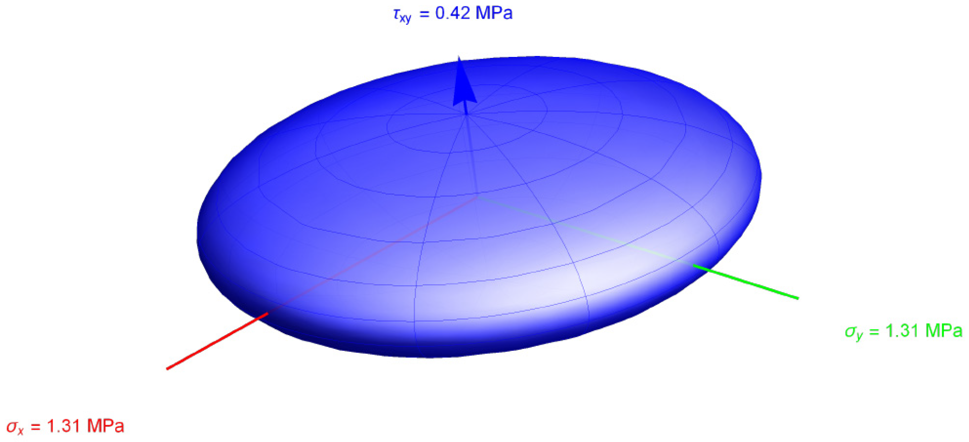
The limit domain obtained with actual stress is compared to the ideal von Mises yield surface for a simple plane stress case with only three stress components to make it visible in
Figure 3. It appears evident that the analysed cubic element is stronger than homogeneous material.
3.2. Equivalent Star System
Geometry
As a representative case study, a lattice structure referred to as the Equivalent Star System (ESS) was investigated to assess the homogenized elastic behavior of the material. Following the definition of appropriate periodic boundary conditions, a numerical analysis of the ESS-based representative volume element (RVE) was conducted. The structure was composed of linear elastic steel members, modeled under the assumption of small strains. The cube containing the RVE had a dimension of 10 mm.
To characterize the effective material behavior, a series of displacement-controlled virtual tests was performed along the principal Cartesian directions. The RVE was subjected to uniaxial tension, compression, and simple shear loadings to extract the stress responses corresponding to the imposed strain fields. From these simulations, the components of the effective stiffness matrix were derived.
The resulting elasticity tensor was then analyzed to identify configurations exhibiting macroscale isotropy. For different configurations, the homogenized Young’s modulus and Poisson’s ratio were calculated, as shown in
Table 2. In particular, the emergence of a negative Poisson’s ratio indicated auxetic behavior, which is a distinctive feature of the geometric layout of the ESS lattice (
Figure 4).
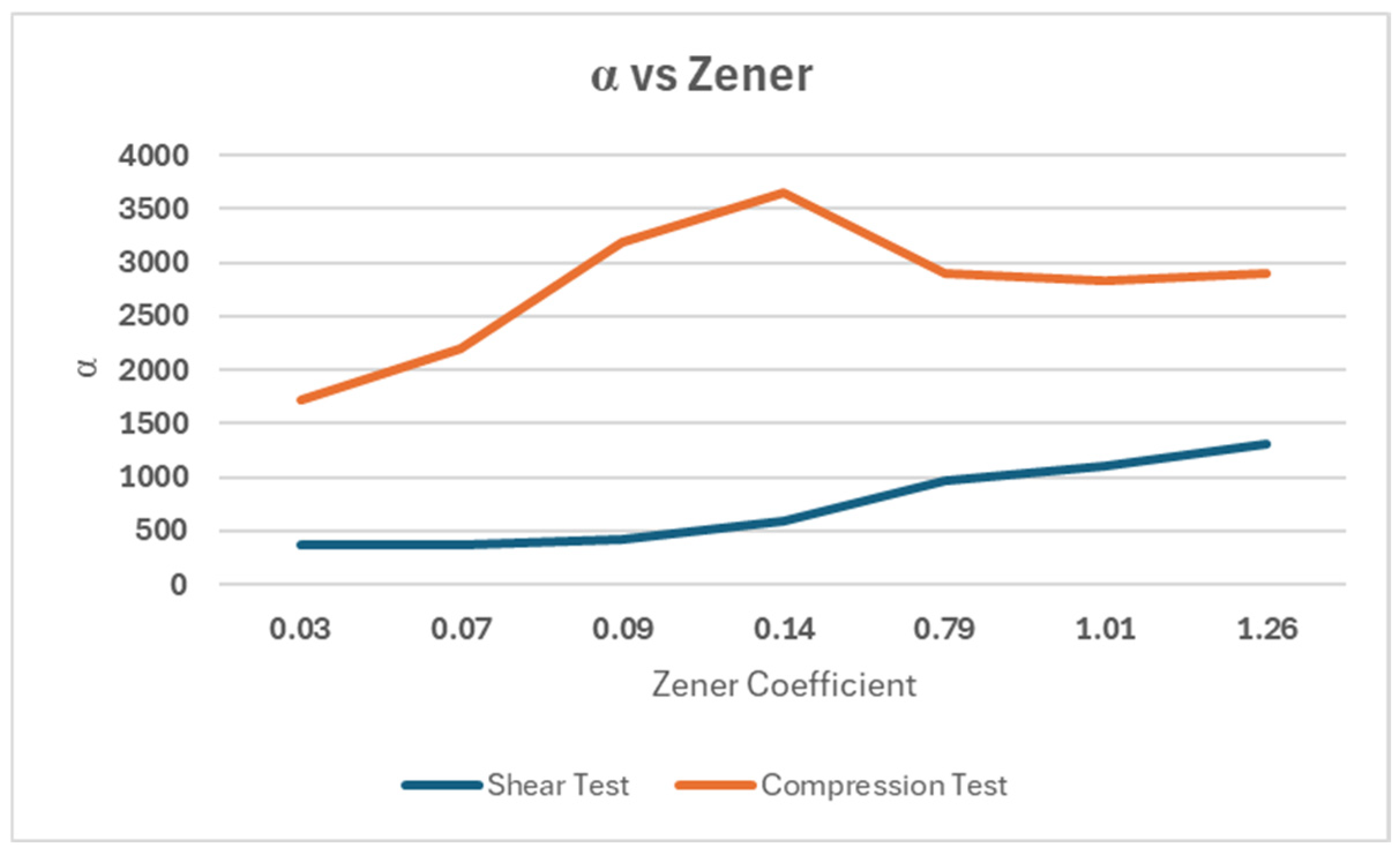
The deformation energy contribution was evaluated for the ESS. The deformation energy was evaluated for various load conditions, including pure compression and pure shear. For each load condition, the energy contribution was evaluated in terms of Extensional Energy (
EE) and Bending Energy (
EB):
For each of the two load conditions, we have Compression Energy Ratio and Shear Energy Ratio, calculated as
The graph presented in
Figure 5 shows the predominance of flexural behavior over extensional behavior, which is particularly evident under compressive stress conditions. In particular, under conditions tending toward isotropy, i.e., for Zener values close to unity, the graphs tend to plateau. Notably, an energy spike occurs at a Zener value of 0.14. This condition corresponds to sections of the same size, from which it is possible to see how strongly the behavior of the lattice structures is influenced by geometry, and how energy assessments and limit analyses can be used for performance-based design.
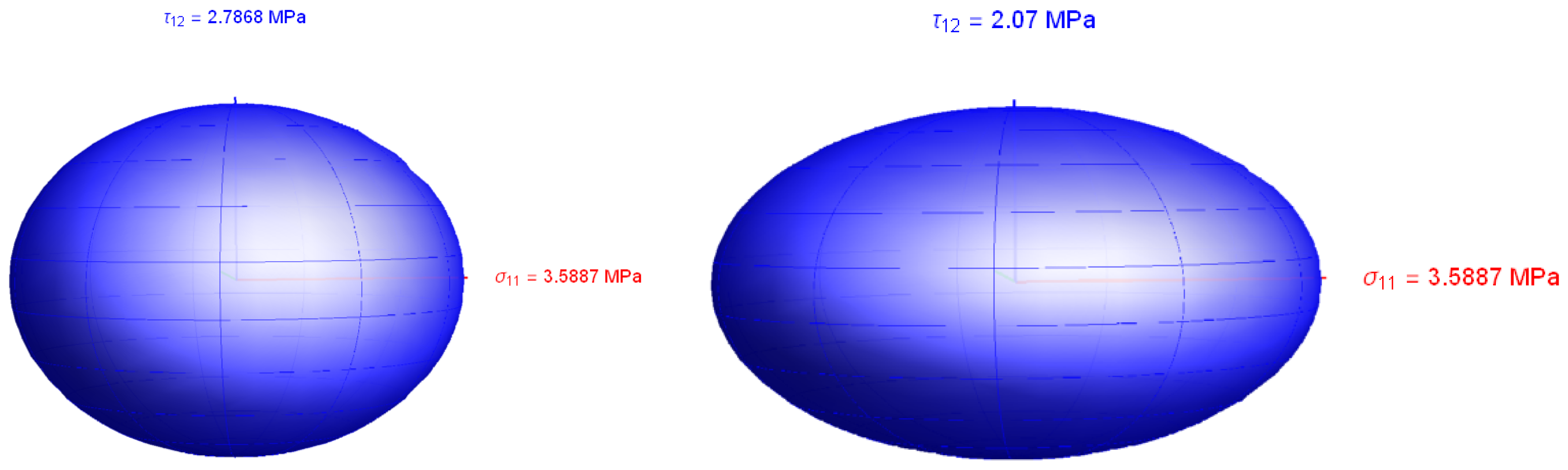
The resulting limit domain is reported in
Figure 6 following, where the ratio between the tensile stress limit and the shear stress limit can be seen to be
three times greater than the ideal von Mises material.
4. Conclusions
This study explored the elastic and plastic mechanical behavior of structured metamaterials by numerically analyzing the response of selected lattice topologies at the microscale. The methodology employed a homogenization framework to evaluate the overall effective elastic properties of representative volume elements (RVEs) from both elastic and plastic behavior. A novel procedure for calculating the yield load of elastic–plastic structures through the finite element implementation of the lower bound method of the limit analysis was applied to plastic homogenization. Several numerical simulations were performed, and a comparison of mechanical performance across different geometries was made, with particular emphasis on the emergence of isotropy in the elastic and yield response.
The numerical experiments highlighted that the investigated cubic elementary cells, despite their geometric symmetry, exhibited anisotropic behavior both in the elastic constitutive law and the yield limit.
In the proposed examples of cubic PC and FCC-shaped RVEs, the dependence of elastic isotropy on the dimensions of the PC and FCC elements, respectively, is highlighted. In particular, the ratio furnishes the best isotropic elastic behavior. Conversely, for the same element, the yield limit stress for the uniaxial normal stress and the uniaxial shear stress ratio is equal to .
The analysis revealed that even in cases where isotropy is achieved in the elastic regime, the corresponding limit domain exhibits significant deviations from the classical von Mises isotropic plasticity. This plastic anisotropy arises not from the constitutive material behavior—which, in the proposed tests, has been kept isotropic—but from the spatial organization and topology of the lattice architecture itself. As such, it highlights a fundamental limitation in the assumption that elastic isotropy implies plastic isotropy, especially in the design of lightweight or energy-absorbing structures.
Finally, in the study, the limit stress threshold was obtained through direct limit analysis using the author’s FEM routine, FELA, which is capable of calculating the limit load without employing a step-by-step iterative and path-dependent routine. The use of FELA allowed the avoidance of path dependence and, hence, was suitable for straightforwardly analyzing the limit domain. The procedure, due to its ease and robustness, is an effective method that can be integrated into forthcoming ultraelastic topology optimization, targeting dual-objective performance: achieving isotropy in both elastic and plastic regimes, and tailoring the collapse mechanism to suit specific functional requirements in engineering design.
Author Contributions
Conceptualization, V.M.; methodology, V.M. and R.Z.; software, V.M.; validation, R.Z.; formal analysis, V.M.; investigation, R.Z.; resources, V.M.; data curation, R.Z.; writing—original draft preparation, V.M. and R.Z.; writing—review and editing, V.M. and R.Z.; visualization, R.Z.; supervision, V.M.; project administration, V.M.; funding acquisition, V.M. All authors have read and agreed to the published version of the manuscript.
Funding
This research was funded by PRIN 2022 PNRR, grant number Prot. P2022Y9ZJ2.
Data Availability Statement
The original contributions presented in this study are included in the article. Further inquiries can be directed to the corresponding author.
Conflicts of Interest
The authors declare no conflicts of interest. The funders had no role in the design of the study; in the collection, analyses, or interpretation of data; in the writing of the manuscript; or in the decision to publish the results.
Abbreviations
The following abbreviations are used in this manuscript:
| FELA | Finite Element Limit Analysis |
| ESS | Equivalent Star System |
| RVE | Representative Volume Element |
| FEM | Finite Element Method |
References
- Cao, Q.; Li, Y.; Wang, Y.; Zhang, J.; Gu, G.X. Characterization and Inverse Design of Stochastic Mechanical Metamaterials. Adv. Mater. 2025, 37, 240063. [Google Scholar] [CrossRef]
- Park, J.; Noh, J.; Shin, J.; Gu, G.X.; Rho, J. Investigating Static and Dynamic Behaviors in 3D Chiral Mechanical Metamaterials by Disentangled Generative Models. Adv. Funct. Mater. 2024, 34, 2412901. [Google Scholar] [CrossRef]
- Chen, Z.; Mordehai, D. Homogenization of the yield surface of body-centered cubic and octet lattice structures under multiaxial loadings. Int. J. Solid Struct. 2025, 320, 113486. [Google Scholar] [CrossRef]
- Zona, R.; Ferla, P.; Minutolo, V. Limit analysis of conical and parabolic domes based on semi-analytical solution. J. Build. Eng. 2021, 44, 103271. [Google Scholar] [CrossRef]
- Zona, R.; Esposito, L.; Palladino, S.; Minutolo, V. Dislocation-Based Finite Element Method for Homogenized Limit Domain Characterization of Structured Metamaterials; Engineering Computations: Swansea, UK, 2024. [Google Scholar] [CrossRef]
- Casciaro, R.; Garcea, G. An iterative method for shakedown analysis. Comput. Methods Appl. Mech. Eng. 2002, 191, 5761–5792. [Google Scholar] [CrossRef]
- Garcea, G.; Armentano, G.; Petrolo, S.; Casciaro, R. Finite element shakedown analysis of two-dimensional structures. Int. J. Numer. Methods Eng. 2005, 63, 1174–1202. [Google Scholar] [CrossRef]
- Fong, E.; Koponen, K.; Omairey, S.; Dunning, P. Developing Mechanical Metamaterials Under an Adaptable Topology Optimization Design Framework. Front. Mech. Eng. 2023, 18, 379. [Google Scholar] [CrossRef]
- Fong, E.; Koponen, K.; Omairey, S.; Dunning, P. Thermal–Mechanical Metamaterial Analysis and Optimization Using Finite-Element Software. Eng. Comput. 2023, 39, 1855–1872. [Google Scholar] [CrossRef]
- Song, J.; Yan, J.; Yi, B. Design, Fabrication, and Characterization of Hierarchical Mechanical Metamaterials. Front. Mech. Eng. 2024, 19, 3. [Google Scholar] [CrossRef]
- Kayacan, M.Y.; Yılmaz, M.S.; Üzün, A. Mechanical Characterization of Meta-Materials Manufactured by a Novel Hybrid SLM Technique Utilizing Powder Metallurgy. Met. Mater. Int. 2024, 30, 280. [Google Scholar] [CrossRef]
- Álvarez-Trejo, A.; Cuan-Urquizo, E.; Bhate, D.; Roman-Flores, A. Mechanical Metamaterials with Topologies Based on Curved Elements. Mater. Des. 2023, 233, 112190. [Google Scholar] [CrossRef]
- Bagheri, M.A.; Aubin, C.-É.; Nault, M.-L.; Villemure, I. Mechanical Characterization of an Origami-Inspired Super Deformable Metamaterial. Mater. Des. 2025, 233, 113701. [Google Scholar] [CrossRef]
- Uddin, K.Z.; Heras, M.; Youssef, G.; Kiel, T.; Koohbor, B. Multiscale Experimental Characterization of Nonlinear Mechanics and auxeyicity in Mechanical Metamaterials with rotating squares. Compos. Struct. 2025, 357, 118931. [Google Scholar] [CrossRef]
- Zhang, Y.; Wang, X.; Liu, H.; Li, Z.; Wang, Y. Reprogrammable Mechanical Metamaterials via Passive and Active Magnetic Interactions. Adv. Mater. 2025, 37, 2412353. [Google Scholar] [CrossRef]
- Lu, M.; Feng, L.; Chen, Y. Recent Progress in Active Mechanical Metamaterials. Adv. Sci. 2021, 8, 2102662. [Google Scholar] [CrossRef]
- Kazim, M.; Pal, A.; Goswami, D. Mechanical Metamaterials for Bioengineering. Adv. Eng. Mater. 2025, 27, 2401806. [Google Scholar] [CrossRef]
- Zhang, Y.; Wang, X.; Liu, H.; Li, Z.; Wang, Y. Mechanical Metamaterials for Sensor and Actuator Applications. Int. J. Precis. Eng. Manuf. 2023, 24, 549–561. [Google Scholar] [CrossRef]
- De Luca, A.; Greco, A.; Perfetto, D.; Sepe, R. Influence of Building Position and Printing Scheme on Mechanical Properties of Fused Filament Fabrication PLA Specimens. In Macromolecular Symposia; Wiley: Hoboken, NJ, USA, 2023; Volume 411. [Google Scholar] [CrossRef]
- Greco, A.; De Luca, A.; Sepe, R.; Gerbino, S. Investigation on tensile properties of FFF PEEK: Effects of printing parameters and post-processing treatment. Procedia Struct. Integr. 2024, 53, 178–184. [Google Scholar] [CrossRef]
- Iandiorio, C.; Serenella, R.; Salvini, P. A Combined Approach of Experimental Testing and Inverse FE Modelling for Determining Homogenized Elastic Properties of Membranes and Plates. Eng. Proc. 2025, 85, 27. [Google Scholar] [CrossRef]
- Mandolesi, B.; Iandiorio, C.; Belardi, V.G.; Vivio, F. Spinodal Decomposition-Inspired Metamaterial: Tailored Homogenized Elastic Properties via the Dimensionless Cahn-Hilliard Equation. Eur. J. Mech. A Solids 2025, 112, 105615. [Google Scholar] [CrossRef]
- Bleich, H. Über die Bemessung statisch unbestimmter Stahltragwerke unter Berücksichtigung des elastisch-plastischen Verhaltens des Baustoffes. Bauingenieur 1932, 19, 261–266. [Google Scholar]
- Melan, E. Der Spannungszustand eines Mises-Henckyschen Kontinuums bei veraender licker Belastung. Sitzber. Akad. Wiss. 1938, 147, 73–78. [Google Scholar]
- Melan, E. Zur Plastizität des räumlicken Kontinuums. Ing. Arch. 1938, 8, 116–126. [Google Scholar] [CrossRef]
- Zona, R.; Minutolo, V. A dislocation-based finite element method for plastic collapse assessment in solid mechanics. Arch. Appl. Mech. 2024, 94, 6. [Google Scholar] [CrossRef]
- Roderic, S. Lakes, Negative-Poisson’s-Ratio Materials: Auxetic Solids. Annu. Rev. Mater. Res. 2017, 47, 63–81. [Google Scholar] [CrossRef]
- Julie, J.A.; Mark, M.C.; Nikola, D.A.; William, S.L.; Logan, B.; Bryan, M.; Alexandra, G.M.; Andrew, P.J.; Eric, D.B.; Kenneth, L.J.; et al. Field responsive mechanical metamaterials. Sci. Adv. 2018, 4, eaau6419. [Google Scholar] [CrossRef]
- Thomson, W.K. (LordKelvin), Elasticity. In Encyclopaedia Britannica; Adam and Charles Black: Edinburgh, UK, 1878. [Google Scholar]
- Cowin, S.C.; Mehrabadi, M.M.; Sadegh, A.M. Kelvin formulation of the anisotropic Hooke’s law. In Modern Theory of Anisotropic Elasticity and Applications; Wu, J.J., Ting, T.C.T., Barnett, D.M., Eds.; SIAM: Philadelphia, PE, USA, 1991; pp. 340–356. [Google Scholar]
- Cowin, S.C.; Mehrabadi, M.M. On the structure of the linear anisotropic elastic symmetries. J. Mech. Phys. Solids 1992, 40, 1459–1472. [Google Scholar] [CrossRef]
- Cowin, S.C.; Mehrabadi, M.M. Anisotropic symmetries of linear elasticity. Appl. Mech. Rev. 1995, 48, 247–285. [Google Scholar] [CrossRef]
- Gurtin, M.E. The linear theory of elasticity. In Encyclopedia der Physics; Flügge, C.S., Truesdel, C., Eds.; Volume I Va/2 Mechanics of Solids II; Springer: Berlin/Heidelberg, Germany, 1972. [Google Scholar] [CrossRef]
- Gazis, D.C.; Tadjbakhsh, I.; Toupin, R.A. The elastic tensor of given symmetry nearest to an anisotropic elastic tensor. Acta Cryst. 1963, 16, 917–922. [Google Scholar] [CrossRef]
- Norris, A.N. The isotropic material closest to a given anisotropic material. J. Mech. Mater. Struc. 2006, 1, 223–238. [Google Scholar] [CrossRef]
- Minutolo, V.; Zona, R. Numerical evaluation of the homogenized limit domain of structured metamaterials, First Hellenic Italia. In Proceedings of the 1st Hellenic-Italian Conference on Computational Mechanics, Biomechanics and Mechanics of Materials HICOMP Conference, Rhodes Island, Greece, 19–21 June 2025; Available online: https://hicomp2025.org/proceedings/pdf/24416.pdf (accessed on 28 May 2025).
| Disclaimer/Publisher’s Note: The statements, opinions and data contained in all publications are solely those of the individual author(s) and contributor(s) and not of MDPI and/or the editor(s). MDPI and/or the editor(s) disclaim responsibility for any injury to people or property resulting from any ideas, methods, instructions or products referred to in the content. |
© 2025 by the authors. Licensee MDPI, Basel, Switzerland. This article is an open access article distributed under the terms and conditions of the Creative Commons Attribution (CC BY) license (https://creativecommons.org/licenses/by/4.0/).


