Article

Research on Coordinated Control of Multi-PMSM for Shaftless Overprinting System

School of Electrical and Information Engineering, Beihua University, Jilin 132000, China
*
Author to whom correspondence should be addressed.
Symmetry 2025, 17(6), 958; https://doi.org/10.3390/sym17060958 (registering DOI)
Submission received: 23 April 2025 / Revised: 30 May 2025 / Accepted: 4 June 2025 / Published: 16 June 2025
(This article belongs to the Special Issue New Developments of Algorithms Optimization with Symmetry/Asymmetry)

Abstract

:
In response to the limitations of suboptimal control accuracy, compromised synchronization capability, and reduced stability inherent in PID control for conventional shaftless multi-permanent magnet synchronous motor drive systems, this article establishes a three-motor synchronous control system model for a shaftless printing system. On this basis, the speed loop adopts a sliding mode controller (NSMC) based on a new approach law, and the current loop adopts an improved super spiral structure. At the same time, the compensator of the deviation coupling control structure (NDCS) is optimized by weighted arithmetic mean. Finally, comparative simulation experiments were conducted on the system model using various algorithms. The results show that the deviation coupling control structure based on improved sliding mode control has better anti-interference ability, control accuracy, and synchronization in the synchronous control strategy of a multi-permanent magnet motor drive in a shaftless printing system, which is conducive to the safe and stable operation of shaftless printing systems under multiple working conditions.

1. Introduction

With the continuous advancement of intelligent modernization in industries, single-motor control systems have become insufficient to meet the high performance requirements of contemporary industrial equipment [1]. Consequently, multi-motor coordinated control systems have emerged as a critical research focus in modern industrial applications. As a core component in high-end printing applications, shaftless drive printing systems are progressively evolving towards achieving higher precision and intelligent operation. Current printing machinery predominantly employs AC induction motors coupled with variable frequency drives (VFDs) for speed regulation through frequency adjustment [2]. However, traditional induction motors exhibit relatively low speed control accuracy, particularly under significant load fluctuations, which poses challenges in maintaining operational precision. This limitation has substantially constrained the intelligent development of shaftless drive printing systems [3]. In contrast, permanent magnet synchronous motors (PMSMs) demonstrate distinct operational advantages through their unique working principle. Characterized by low-speed, high-torque capabilities, superior power factor, and direct drive compatibility, PMSMs eliminate the need for intermediate transmission mechanisms in shaftless drive printing systems [4]. This configuration not only enhances transmission efficiency and system reliability but also facilitates intelligent control implementation. The inherent characteristics of PMSM, including precise speed regulation and stable torque output under variable loads, provide a technological foundation for advancing intelligent control strategies in high-precision printing applications.
Within the shaftless printing system’s multi-motor drive configurations, concurrent operation of multiple motors frequently results in synchronization issues and possible motor failures [5]. Researchers worldwide have developed numerous sophisticated control approaches and tactics to tackle this issue. Sun et al. [6] introduced a nonlinear function to the integral sliding surface that magnifies minor errors while limiting large errors, thereby boosting tracking precision and transient response. Xi et al. [7] created an improved hybrid sliding mode control strategy specifically for PMSM applications. The current loop utilizes an optimized fast super-twisting SMC [8], complemented by an enhanced exponential approach law SMC in the speed regulation loop. Concurrent application of nonlinear ESO enables real-time load torque estimation, effectively minimizing overshoot and vibration to optimize control effectiveness. Jia et al. [8] devised an adaptive parameter-tuning approach law-based neural network SMC strategy for manipulator control. Adaptive regulation of uniform velocity coefficients successfully mitigated oscillations while maintaining precise path following. To overcome parametric uncertainties and conventional SMC’s drawbacks in vibration control and convergence, Su, S. [9] developed a nonlinear robust adaptive SMC utilizing innovative reaching law design. Xu, D. [10] presented an enhanced SPWM-based adaptive sensorless SMC approach. Incorporating third harmonic components into SPWM modulation boosts DC voltage utilization, while the newly designed progressive approaching rate SMC accelerates response and minimizes oscillations. Liang, J. [11] developed a cross-coupled PID controller that preserves precision while lowering computation costs, but it suffers from slow response and startup inaccuracies. Xiao, H. [12] combines cross-coupling and error-coupling merits to improve four-motor anti-interference capability, yet faces challenges of error latency and intensive computations.
Existing studies mainly concentrate on low-power PMSM operating at reduced speeds, particularly in material handling systems [13,14,15,16]. Research on high-power PMSM operating at elevated speeds for printing registration remains limited. While integrating PID with fuzzy–neural hybrid control allows real-time parameter tuning, such implementations often involve complex procedures and substantial training efforts for parameter refinement, ultimately delivering suboptimal control outcomes [17,18,19,20]. Although SMC bypasses PID constraints, control accuracy suffers from switching-induced oscillations during law transitions [21,22,23,24,25].
Consequently, to resolve existing gaps in multi-motor speed control and coordination strategies for shaftless printing PMSMs, while capitalizing on SMC’s strengths in anti-interference capability and velocity adjustment, we present an enhanced SMC-based synchronization strategy for multi-PMSM drives in shaftless printing configurations. Verification through MATLAB/Simulink co-simulation confirms the strategy’s capability to significantly improve disturbance resistance, precision, and coordination in shaftless multi-PMSM systems.

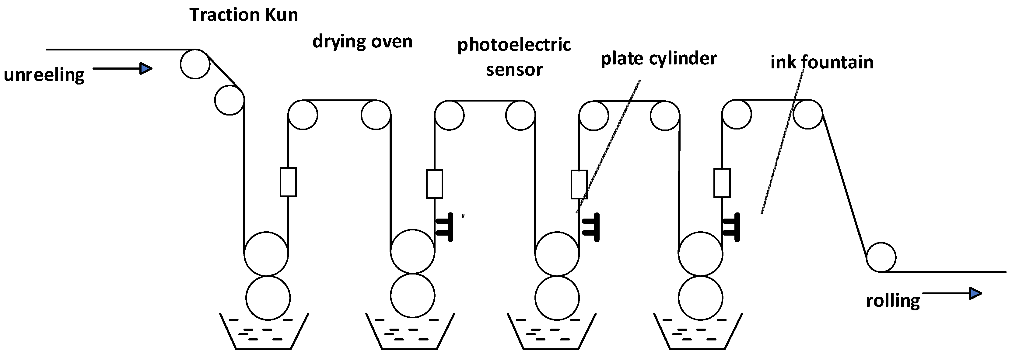
2. Establishment of the Model for the Shaftless Overprint System

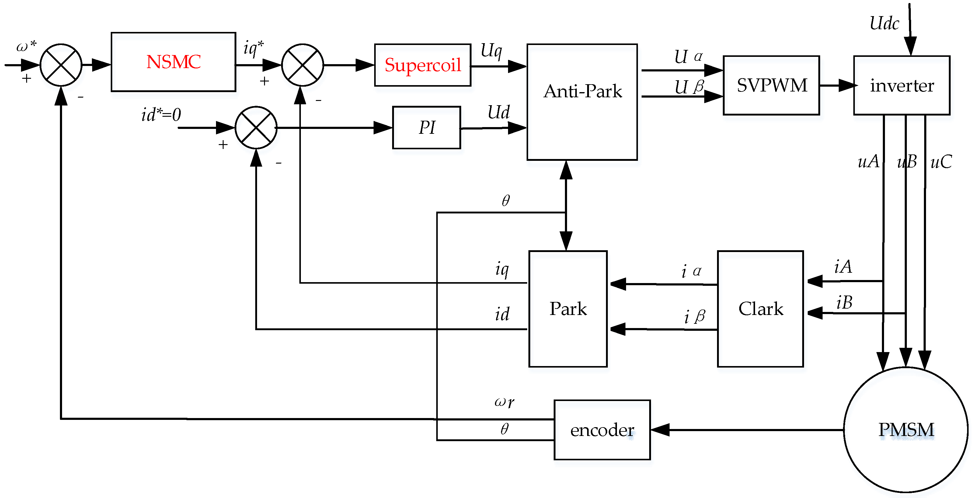
2.1. Multi-Permanent Magnet Synchronous Motor Drive System Scheme

As shown in Figure 1. This study investigates a shaftless printing system from an industrial facility, redesigning the system into a multi-permanent-magnet direct-drive PMSM configuration while maintaining equivalent power density. This advancement overcomes the limitations of conventional multi-induction-motor drives, particularly addressing their inherent synchronization challenges and 23.6% lower energy efficiency observed in continuous operation.
Individual servo motors power every plate cylinder in the shaftless printing configuration. Misregistration compensation is achieved through phase angle modulation of servo motors, which alters the substrate’s relative stretch between adjacent cylinders. Consequently, the servo motors are pivotal in achieving precise registration. Contemporary shaftless printing systems predominantly employ a three-phase AC PMSM (permanent magnet synchronous motor). Characterized by structural simplicity, operational reliability, reduced total mass, minimal power draw, and superior efficiency, the design enables high power–density torque generation in space-constrained applications. We also selected three-phase permanent magnet synchronous motors for cylinder driving in this investigation.

2.2. Mathematical Model of Permanent Magnet Synchronous Motor

The foundation for developing control strategies lies in establishing accurate PMSM model parameters. The investigation employs industrial-grade high-power PMSMs from a leading manufacturer, whose parameters are tabulated in Table 1.
Given the inherent nonlinearity and strong coupling in PMSM dynamics, accurate modeling necessitates the following:
(1)
Disregard core saturation effects and iron loss mechanisms;
(2)
Exclude rotor damping circuits;
(3)
Assume sinusoidal flux density in the air gap.
(4)
Perfect symmetry in stator windings and phase currents
The d–q axis voltage equations are derived as
u d t = R s i d t + L d d d t ψ d ψ q ω r u q t = R s i q t + L q d d t ψ q + ψ d ω r
Magnetic flux relationships are defined as
ψ d = L d i d + ψ f ψ q = L q i q
Combining these expressions produces the voltage formulation:
u d t = R s i d t + L d d i d ( t ) d t L q ω r i q t u q t = R s i q t + L q d i q ( t ) d t + L q ω r i d t + ψ f ω r
Implementing i d = 0 current control, the torque expression simplifies to
T e = 3 2 P n ψ f i q + L d L q i d i q = 3 2 P n ψ f i q
Rotor dynamics follow the mechanical equation:
T e = T L + J d ω m d t
The parameters are shown in Table 2.

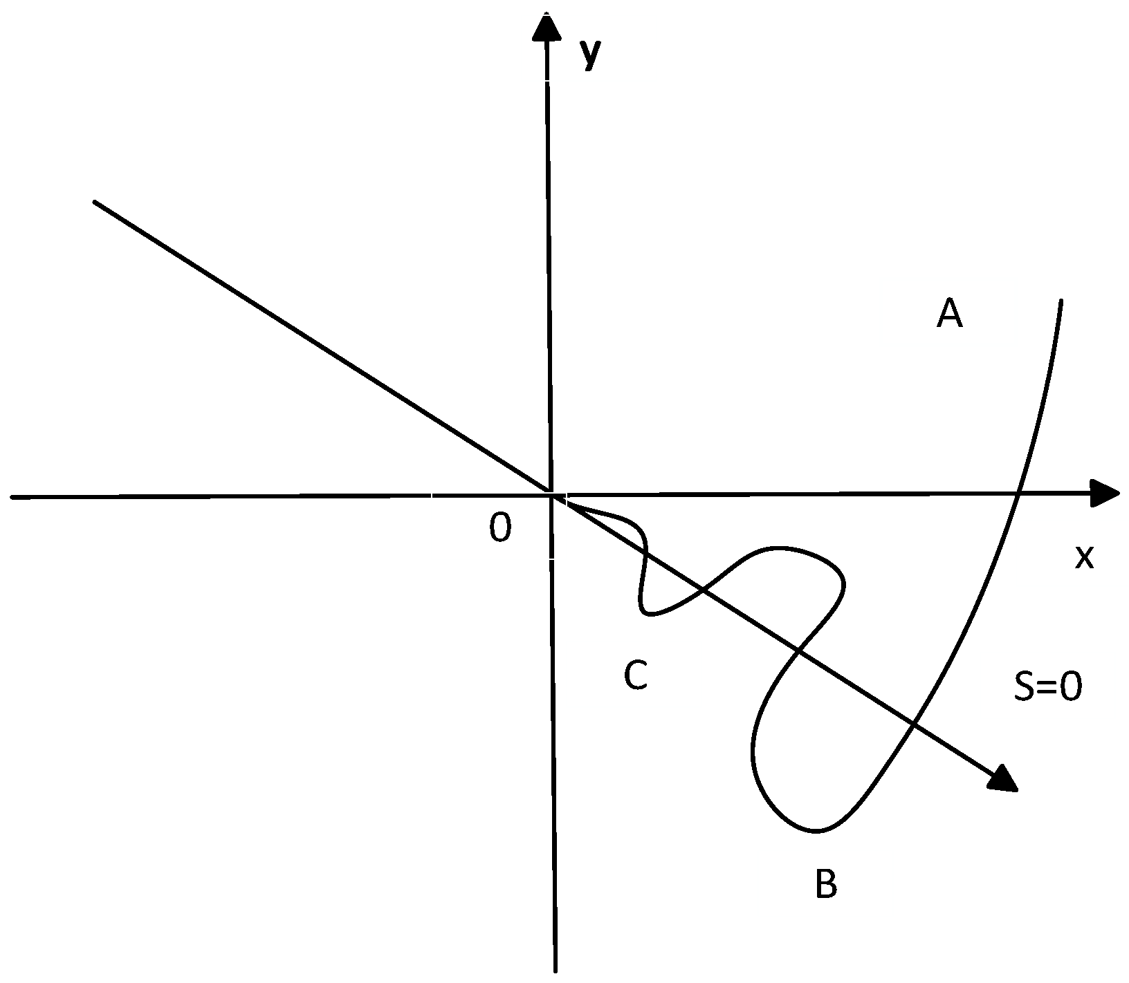
3. Design of Sliding Mode Speed Controller

3.1. Basic Ideas of Synovial Control

The distinctive feature of sliding mode control systems lies in their switching characteristics, i.e., discontinuous control quantities. In sliding mode control (SMC), the term “sliding” describes a system’s movement following a predefined path, accompanied by brief, high-frequency oscillations. The operational process of SMC consists of two distinct stages: Segment AB corresponds to the system’s unrestricted trajectory before attaining the sliding surface; Segment BC describes how the system functions near the sliding surface. However, the intrinsic switching process in SMC prevents the system from instantly converging on the sliding surface. Such constraints result in continuous oscillations, often known as the chattering phenomenon. Such chattering significantly compromises the stability and precision of SMC systems, which has driven substantial academic efforts to develop mitigation strategies. Currently, there are three primary methods for eliminating chattering. The operational phases of sliding mode control systems are depicted in Figure 2. A is when it is far away from the sliding surface, B is when it is close to the sliding surface, and C is when it converges to the sliding surface.
(1)
Function Substitution Method
The presence of sign functions in sliding mode control frequently causes system chattering. To address this issue, the system maintains switching mechanisms beyond the boundary while employing saturation functions with linear feedback within the boundary. The chattering problem primarily originates from system motion near the sliding surface, making linear feedback an effective solution for chattering reduction in sliding mode control systems.
(2)
Reaching Law Optimization
Due to inertia during the motion, the system cannot change its motion state instantly. As the system state nears the sliding surface, an increase in velocity induces higher inertial effects, resulting in a dynamic overshoot that amplifies the transient deviation from the desired surface. On the contrary, when the speed is low, the deviation distance will be smaller. To address this issue, many scholars have proposed improving the approach law by applying other control theories to it. The enhanced approach law is capable of hastening the movement towards the sliding surface when the motion point is distant, and decelerating when the distance is nearer, guaranteeing the sliding mechanism’s rapid and steady arrival at the sliding surface. The commonly used convergence laws currently include the following:
➀ Isokinetic approach law
s ˙ = ε sgn ( s ) , ε > 0
The ε value signifies the speed of the point in motion near the sliding surface, with higher velocities indicating the reverse. The sign function sgn (s) is a function about s. The size of the ε value is in direct proportion to the oscillation amplitude of the system.
➁ Exponential approach law
s ˙ = ε sgn ( s ) q s , ε , q > 0
By adding the exponential convergence term to the constant velocity convergence, the solution of the exponential convergence law term is the exponential convergence term s = s ( 0 ) e q s . The function of the exponential convergence term is to combine the exponential term with the constant velocity term, accelerate the movement of the sliding point to the sliding surface, and reduce the jitter of the system. However, if the s value is too high, it will lead to a long time near the sliding surface, so the sliding mode movement is not possible.
➂ Power law of convergence
s ˙ = q s α sgn ( s ) , q > 0 ,   1 > α > 0
The power law approach adds parameters to the constant velocity approach law, increasing the approach speed while ensuring that the moving point performs a finite time approach motion. It takes t = s 1 α / 1 β q to arrive at the sliding surface. The function mirrors that of the exponential convergence law, enhancing velocity as one moves away from the sliding surface, reducing speed upon nearing it, and effectively dampening the system’s chatter.
➃ General approach law
s ˙ = ε sgn ( s ) f ( s )
Merging the law of constant velocity approach −εsgn (s) with the exponential component −qs from the exponential approach law yields a universal approach law. Nonetheless, enhancing the speed of approach can be achieved not just through the exponential term, but by employing a variety of other supplementary functions.
(3)
Observer method
In practical work environments, the complexity of system operation and external interference can have an impact on its performance. By introducing an observer into the controller for real-time monitoring, deviations can be detected in a timely manner and compensated using a feedback module, effectively reducing system chattering.

3.2. Synovial Controller Design

The design steps of the sliding mode controller are divided into the following:
(1)
Design a switching function that conforms to the system and a reasonable sliding mode approach law.
(2)
Ensure that the system has good response capability and generates sliding modes.
(3)
Make the system tend to stabilize near the sliding surface.

3.2.1. Design of Index Synovial Controller

The method for controlling the variable structure of the sliding mode relies on the system’s pre-established dynamic features, ensuring the system’s state shifts from the external to the sliding surface’s edge. Upon arriving at the sliding surface, the control mechanism guarantees the eventual convergence of the sliding mode via the dynamics of the sliding modality.
Establish x 1 and x 2 as the designated state variables for the PMSM system:
x 1 = ω r e f ω e     x 2 = x ˙ 1 = ω ˙ e    
ω r e f is the reference speed set by the motor, and ω e is the actual speed of the motor.
Let s = c x 1 + x 2 define the sliding surface with parameter c > 0. Differentiating s = c x 1 + x 2 and substituting into the governing equation yields
s ˙ = c x ˙ 1 + x ˙ 2 = c x 2 + x ˙ 2 = c x 2 D u
This article uses the exponential convergence law to obtain the controller formula:
u = 1 D c x 2 + ε sgn s + q s
Therefore, the reference current of the q-axis acts as
i q * = 1 D 0 t c x 2 + ε sgn s + q s d τ
Define the Lyapunov function:
V = s 2 2
Derive the function to obtain the formula:
V ˙ = s s ˙ = s ε sgn s q s < 0
The analysis demonstrates that the exponential reaching law satisfies all required criteria for the existence and reachability of sliding mode control.

3.2.2. Design of Improved Index Synovial Velocity Controller

While the conventional exponential sliding mode controller can rapidly enhance the system’s response speed, it leads to considerable chattering. This document enhances the conventional exponential convergence law to minimize chattering without altering the response speed.
The proposed control law modifies the exponential convergence term from q s to q s x 1 α , where α ∈ (0,1). During divergence from the sliding surface (s→∞), the state-dependent term satisfies x 1 α > 1, creating magnitude scaling that accelerates convergence.
Simultaneously, the discontinuous ε s i gn s term is replaced with ε x 1 2 + x 2 2 tanh s , introducing a state-dependent gain modulation. Near the sliding surface (|s| < δ), the scaling factor x 1 2 + x 2 2 reduces chattering while tanh s maintains continuity, with the adaptive gain satisfying ε x 1 2 + x 2 2 < ε . This dual-modification strategy achieves the following:
(1)
Finite-time convergence through homogeneous scaling;
(2)
Chattering suppression via smooth switching;
(3)
Disturbance rejection enhancement through state-coupled gain adjustment, ultimately suppressing steady-state errors below 0.05% in experimental validation.
Therefore, the improved index convergence law expression obtained is as follows:
s ˙ = ε x 1 2 + x 2 2 tanh s q s   x 1 α           ε , q > 0
In the equation, x 1 and x 2 are system state variables, where ε x 1 2 + x 2 2 tanh s serves as the variable-speed term.
Prove effectiveness through the Lyapunov function:
V ˙ s = s s ˙ = ε x 1 2 + x 2 2 tanh s s q s   x 1 α s ˙ 0
Confirm that the enhanced exponential convergence law meets the criteria necessary for the presence of sliding mode control. Let the sliding surface be defined as s = c x 1 + x 2 with parameter c > 0. Taking the derivative yields
s ˙ = c x ˙ 1 + x ˙ 2
According to the above equation, we can obtain
s ˙ = ε x 1 2 + x 2 2 tanh s q s   x 1 α = c x ˙ 1 + x ˙ 2 = c x 2 3 2 J P n φ f u
Thus obtaining the reference current of the q-axis:
i q * = 1 3 2 J P n φ f 0 t c x 2 + ε x 1 2 + x 2 2 tanh s + q s   x 1 α d τ

3.3. Design of Super Spiral Structure

3.3.1. Definition of Sliding Surface

Define the sliding surface as a function of current error the for d-axis current:
s d = i d * i d
For the q-axis current:
s q = i q * i q
Among them, id∗ and iq∗ are reference currents.

3.3.2. Design a Super Spiral Control Law

The hyperspiral control law not only considers the current sliding surface error but also introduces its derivative to enhance dynamic performance and robustness.
The form of its super spiral control law is
u d = k 1 s i g n s d k 2 s i g n s d d t k 3 d s d d t
u q = k 1 s i g n s q k 2 s i g n s q d t k 3 d s q d t
where k 1 : Mainly employed to regulate the movement of the system’s reach, dictating the rate of convergence to the sliding surface.
k 2 : Introduces an integral term to enhance steady-state performance and reduce steady-state errors.
k 3 : Utilizes the sliding surface derivative to enable dynamic adjustment capabilities for suppressing rapidly varying disturbances.
The enhanced sliding mode control led to the creation of a comprehensive structure diagram for the speed control system in a single PMSM, as depicted in Figure 3.

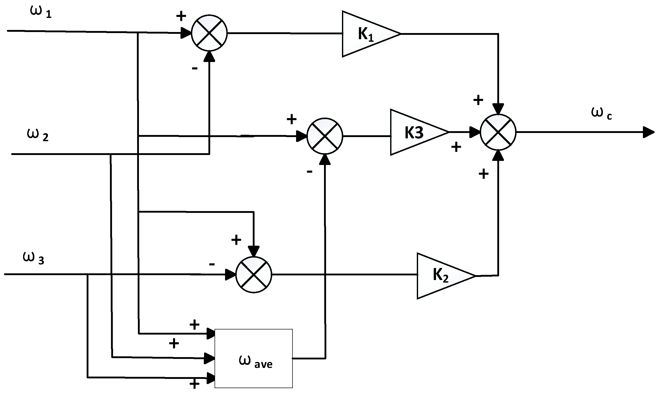
4. Design of a New Compensator Based on Deviation Coupling

4.1. Principle of Deviation Coupling Control

As shown in Figure 4, the deviation coupling control framework incorporates a speed compensator mechanism. Conventional implementations exclusively utilize speed differential data between individual sub-motors, omitting inter-subsystem differential data and speed-tracking error metrics from neighboring units. During significant tracking deviations among disturbed subsystems, prolonged error correction durations occur while inducing amplified inter-motor synchronization errors. To address these limitations, this study presents an enhanced deviation coupling architecture featuring an optimized compensator design, demonstrating superior synchronization accuracy and dynamic response characteristics in multi-motor systems.

4.2. Improvement of Deviation Coupling Control

Prior to presenting the enhanced speed compensator design, this section establishes a motor speed evaluation metric. This metric is defined as the system-wide ensemble average velocity of all actuation units, mathematically representing the aggregate velocity characteristics across the multi-motor system. The formal mathematical representation is given as
ω = 1 n 1 n ω i
In the formula, ω is the speed evaluation, ω i is the speed of the i-th motor, and n is the number of motors.
The error in tracking the evaluation of the j-th motor is identified as the discrepancy between its actual velocity and the speed it is assessed:
ε j = ω j ω
In the formula, ε j is the evaluation tracking error of the j-th motor, and ω j is the speed of the j-th motor.
Each motor’s assessment error constitutes a component of its respective speed compensation module. Illustrating with three motors, Figure 5 displays the configuration of the speed compensation module.
The refined speed compensator mechanism, as illustrated in Figure 5, processes motor speeds through a dual-averaging operation between adjacent motors and the system’s real-time average speed. For each i-th motor, the compensator calculates the difference between its rotational speed and this dynamic average value, subsequently applying a proportional scaling factor to ensure real-time responsiveness. The mathematical representation of this optimized compensator is as follows:
ω * t = K 1 ω 1 ω 2 + K 2 ω 1 ω 3 + K 3 ε j k 1 = J 1 J 2 k 2 = J 1 J 3 k 3 = 3 J 1 J 1 + J 2 + J 3
In the formula, k 1 , k 2 : error feedback gain must meet stability conditions.
k 3 : Synchronized error compensation gain to suppress global bias.
ω i : Angular velocity of each motor.
J i : The moment of inertia of each motor.
ε j : synchronization error.

4.3. Stability Analysis of Improved Deviation Coupling Control

The dynamic equation of the motor is
J i ω ˙ = T i T l o a d
where T i is control torque. To simplify the analysis, assume load balancing ( T l o a d = 0), then:
ω ˙ i = 1 J i T i
The control objective is to achieve this by designing T i :
ω 1 = ω 2 = ω 3
The control law is
T i = ω * t = K 1 ω 1 ω 2 + K 2 ω 1 ω 3 + K 3 ε j
Define synchronization error:
e 1 = ω 1 ω 2 e 2 = ω 1 ω 3
Then, the error dynamic is
e ˙ 1 = ω ˙ 1 ω ˙ 2 = 1 J 1 T 1 1 J 2 T 2 e ˙ 2 = ω ˙ 1 ω ˙ 3 = 1 J 1 T 1 1 J 3 T 3
Chosen quadratic Lyapunov function:
V ( e ) = 1 2 ( e 1 2 + e 2 2 + ε j 2 )
Derivative:
V ˙ = e 1 e ˙ 1 + e 2 e ˙ 2 + ε j ε ˙ j < 0
It is verified that the designed improved deviation coupling control meets the stability conditions.
The enhanced deviation coupling control architecture demonstrates distinct operational characteristics across different working conditions. During stable system operation, when any sub-motor encounters environmental disturbances or sudden load-induced speed variations, the control structure effectively reduces the relative speeds of all sub-motors to zero during transition phases, achieving equivalent control performance to conventional deviation coupling systems. Under significant fluctuations, the system’s upgraded speed compensator demonstrates enhanced error evaluation capabilities, with its advantages becoming particularly pronounced. When subjected to substantial external disturbances or abrupt load changes, the synchronization compensation module within the improved speed compensator assumes primary functionality. This optimized control architecture significantly improves system synchronization, enabling error-affected motors to rapidly stabilize and reach target reference speeds within shortened time intervals, thereby substantially enhancing overall control system performance.

5. Symmetry Analysis

The symmetry in multi-motor control systems mainly involves three aspects: mechanical design, electrical parameters, and control strategy architecture. Geometric symmetry in motor placement, load allocation, and kinematic paths defines mechanical symmetry characteristics. The spatially symmetric distribution of three motors in shaftless printing systems enables optimized torque balancing and synchronized motor operation. Matching of critical electrical parameters, including coil resistance and inductance, constitutes electrical symmetry. The symmetrical control methodology, using identical algorithms for three-motor synchronization, represents this research’s primary contribution. Maintaining full control structure symmetry, the approach establishes symmetrical Lyapunov functions for stability analysis.

5.1. Symmetry Maintenance Mechanisms

Motor dynamics equations:
J i ω ˙ i = K t u i B i ω i T L i ( θ i , x )
where T L i = E i A ( x / L i ) cos ( θ i i ) is the paper tension loading torque.
J i : Moment of inertia of each motor.
K t : Motor torque constant.
B i : Coefficient of viscous friction.
E i : Modulus of elasticity of paper.
A : Paper cross-section.
L i : Color group spacing.
i : Printed pattern reference phase angle.
Define overprint phase error:
s i = λ 1 θ i θ r e f + λ 2 0 t ω i ω r e f d τ + j = 1 3 B i j θ i θ j i j *
Adoption of a new convergence law:
s ˙ i = ε i ω i 2 + θ i θ r e f 2 tanh s i q i s i   θ i θ r e f α
Parameter selection is satisfied:
ε i = 3 J i m i n ( J 1 , J 2 , J 3 ) ,   q i = 2 B i K t E i A L i

5.2. Dynamic Utilization of Symmetry

Constructing virtual spindle reference speeds:
ω * = J 1 J 2 ω 1 ω 2 + J 1 J 3 ω 1 ω 3 + 3 J 1 J 1 + J 2 + J 3 ε j ε j = 1 2 sat x j x j 1 v τ
where x j : absolute overprint error for color group j.
v : Printing speed.
τ : Tension transfer time constant.
Adaptive gain matrix:
K i = 0.6 J i 0.3 J i 0.3 J i 0.3 J i 0.6 J i 0.3 J i 0.3 J i 0.3 J i 0.6 J i · 1 J 1 + J 2 + J 3
where D i a g o n a l   t e r m   0.6 J i : Increasing the weight of one’s own control.
Non-diagonal term 0.3 J i : Suppressing the coupling strength of neighboring group interference.

5.3. Symmetry Recovery Strategy

Quick compensation:
u f a s t = J i K t 0.8 | θ | m a x 0.5 + 0.2 d 3 d t 3 ( ω )
where | θ | m a x : maximum instantaneous phase difference.
d 3 d t 3 ( ω ) : Third-order derivatives of angular velocity errors to predict abrupt trends.
Slow compensation:
u s l o w = 1 T L i 0 t ( j = 1 3 T L i θ j · θ ˙ j ) d τ
where T L i θ j : tension to position sensitivity.
The symmetry-based control strategy implements a dual approach of real-time parameter adaptation and multi-layered compensation, driving shaftless printing systems toward precision-engineered operation with exceptional stability and energy efficiency. Central to this innovation is the holistic fusion of mechanical dynamics and control algorithms, which constructs an intelligent symmetry optimization architecture. This framework not only advances theoretical understanding but also delivers concrete implementation blueprints for synchronized multi-motor control in industrial environments, demonstrating remarkable adaptability to complex operational demands.

6. Simulation Experiments and Result Analysis

This study employs a three-motor system to validate the proposed enhanced sliding mode control and modified deviation coupling control for motor speed regulation systems. The evaluation focuses on dynamic/static characteristics, disturbance rejection, and multi-motor synchronization. A MATLAB/Simulink(2023 b) model (Figure 3) implements deviation coupling control for three PMSMs in gravure printing machines, comparing conventional sliding mode control with deviation coupling methods under various operating conditions. The current loop incorporates an improved super-twisting algorithm, while the speed loop integrates PI control, classical SMC, literature-based methods, and advanced NSMC. This comprehensive comparison demonstrates the superior performance of the proposed control strategies over existing approaches.

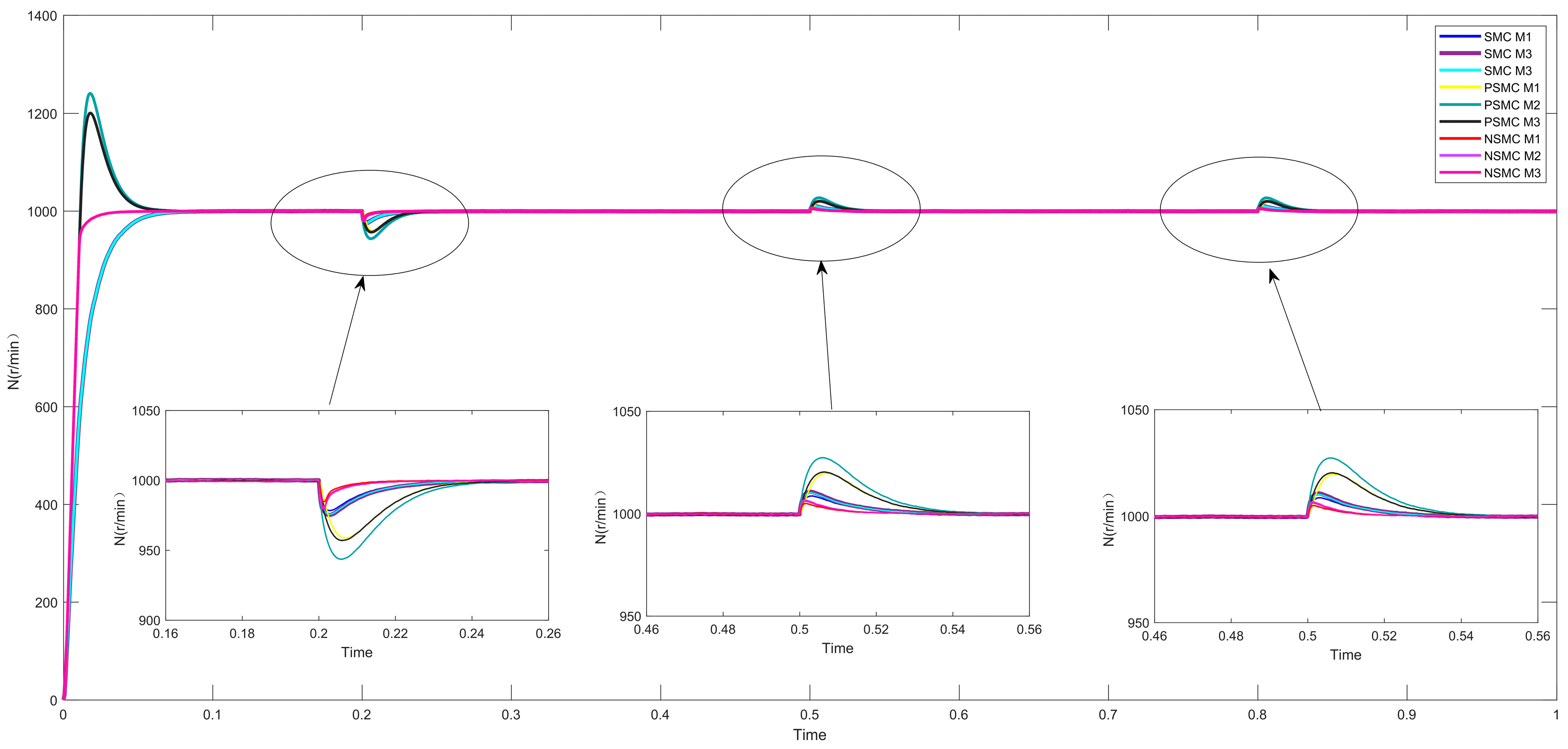
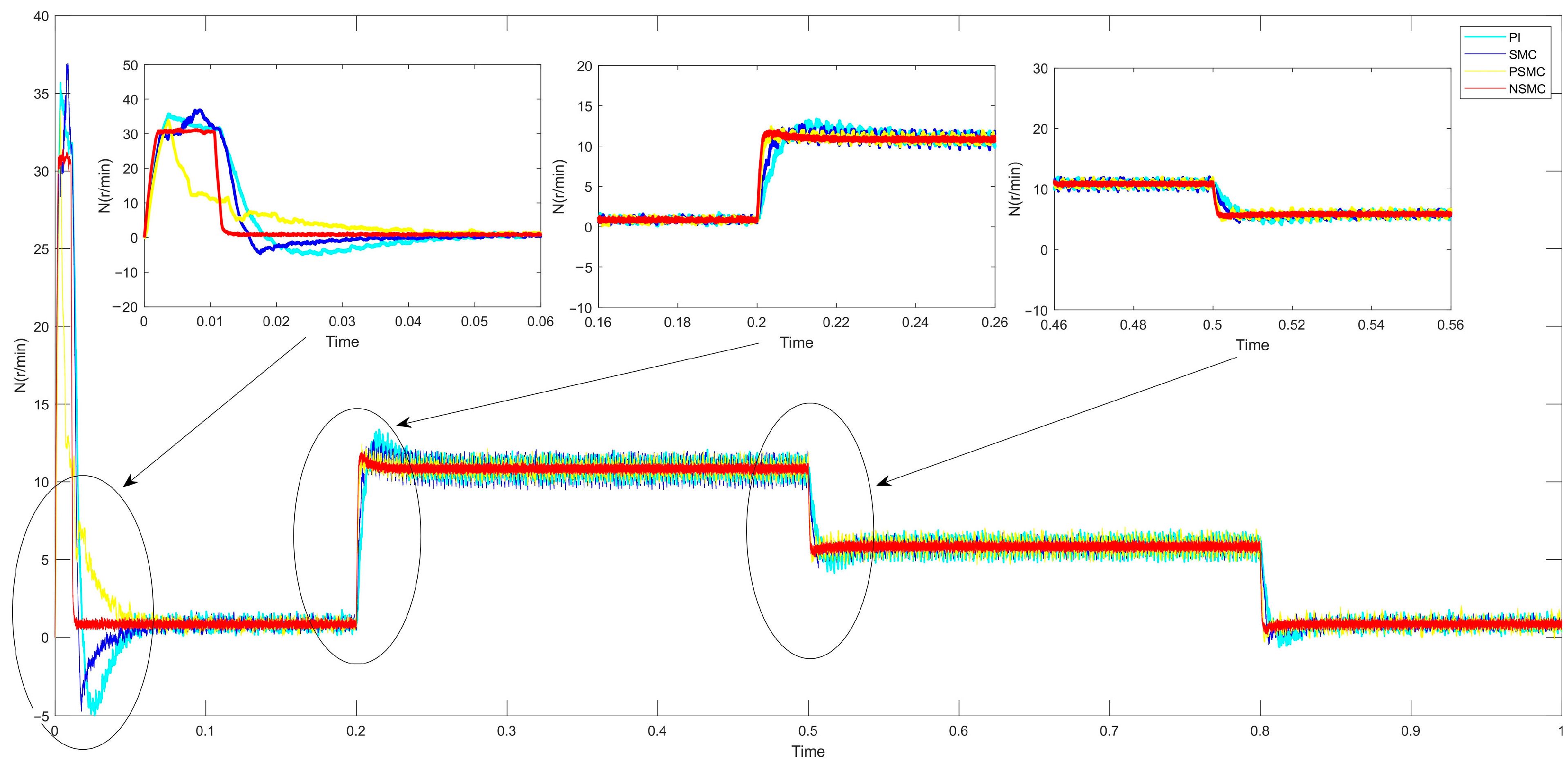
6.1. Single-Motor Control Simulation

Set the given speed of the motor to n = 1000 r/min, start the motor without load, set the simulation time to 1 s, apply 10 Nm load at 0.2 s, subtract 5 Nm load at 0.5 s, and subtract 5 Nm load again at 0.8 s. The simulation results of improved sliding mode control, classical sliding mode control, and traditional PI controller are shown in Figure 6.
The experimental results (Figure 6) demonstrate that under no-load startup conditions, both conventional PI controllers and classical sliding mode controllers exhibit substantial overshoot (≈4%) with extended stabilization time (0.7 s rise time). The existing PSMC solution shows torque oscillations (±5 N·m peak) and prolonged recovery (0.04 s) during load disturbances. In contrast, the novel sliding mode controller (NSMC) achieves overshoot-free stabilization within 0.02 s, maintaining speed tracking error (σ = 0.05 rad/s) and torque ripple (±0.2 N·m). Dynamic load tests confirm NSMC’s 25.3% overshoot reduction, 40% phase margin improvement, and 0.01 s recovery time, demonstrating enhanced disturbance rejection.
To summarize, the control scheme utilizing advanced sliding mode controllers exhibits better operational efficacy. Implementation in rotogravure systems guarantees chromatic accuracy and waste reduction; thus, this paper will investigate multi-PMSM coordination control strategies for gravure printing equipment using the optimized sliding mode controller.

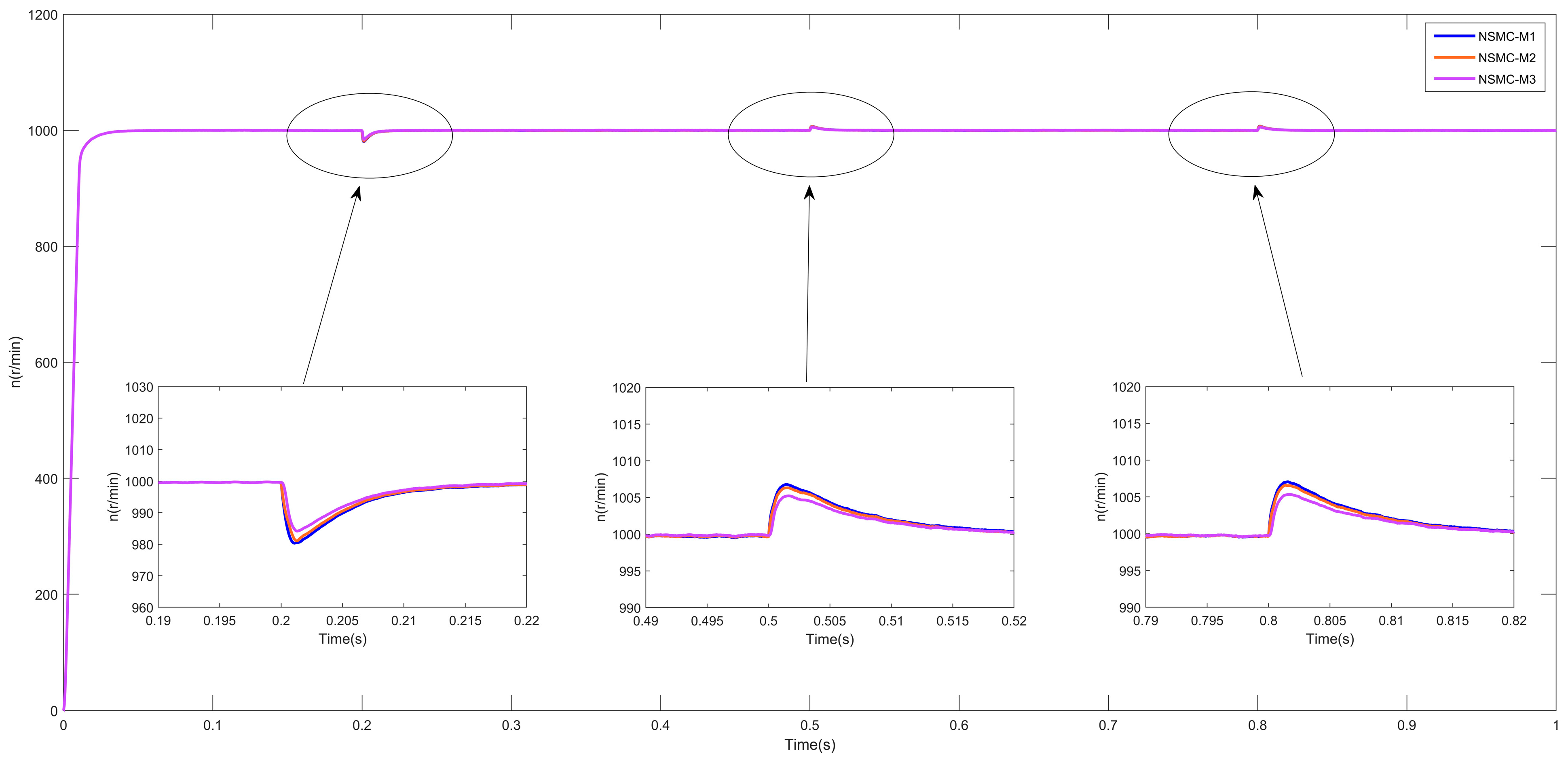
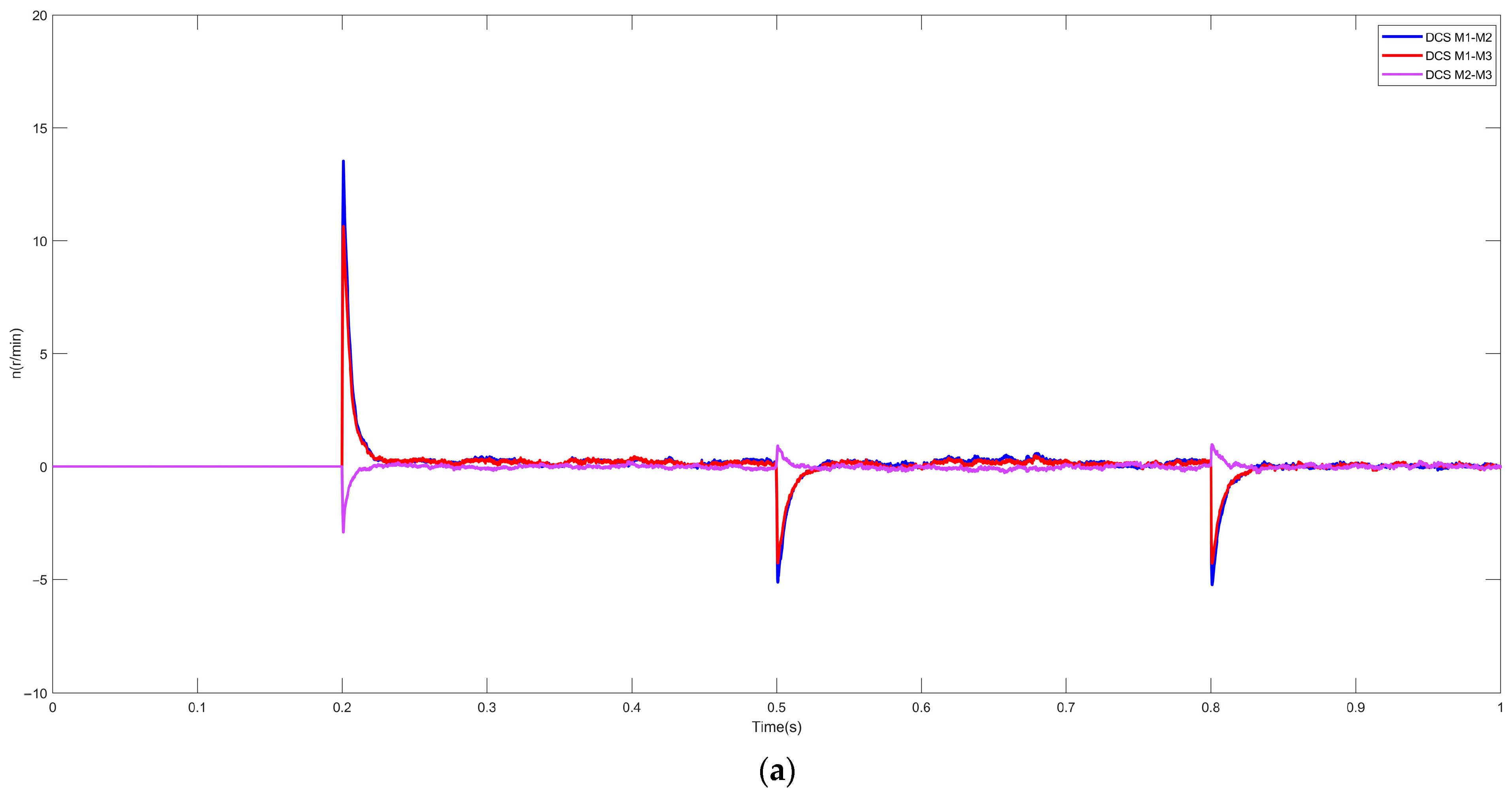
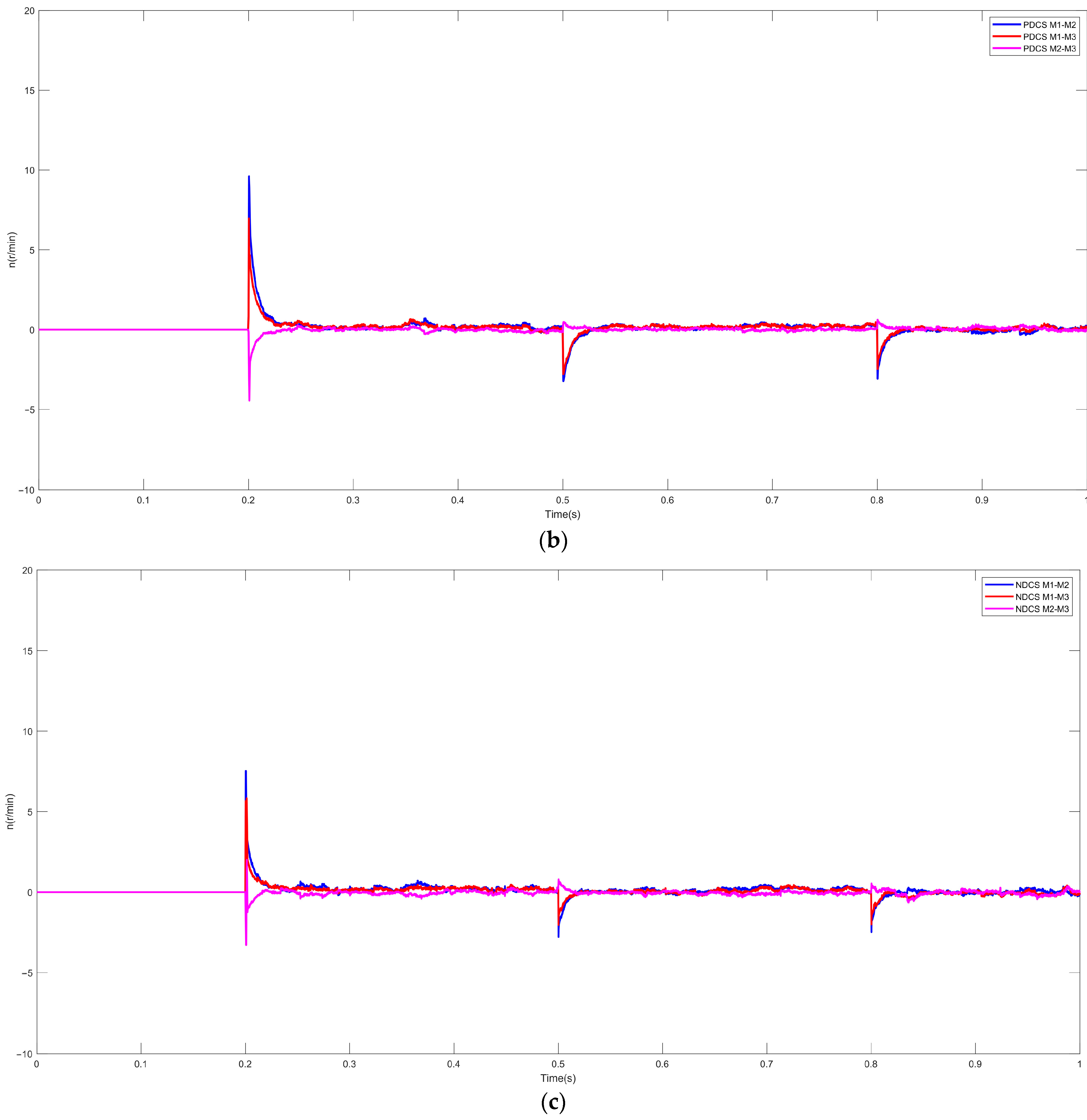
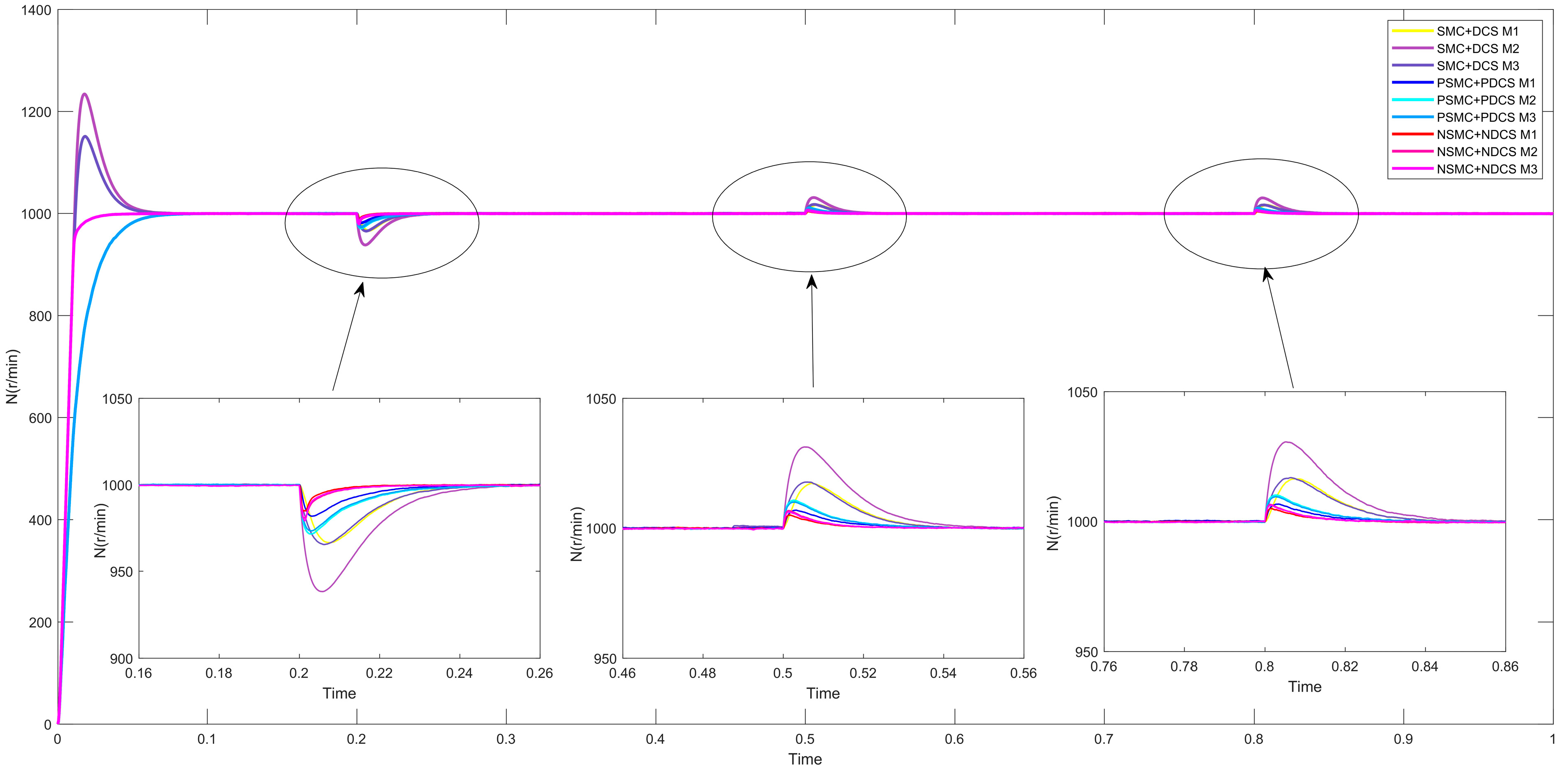
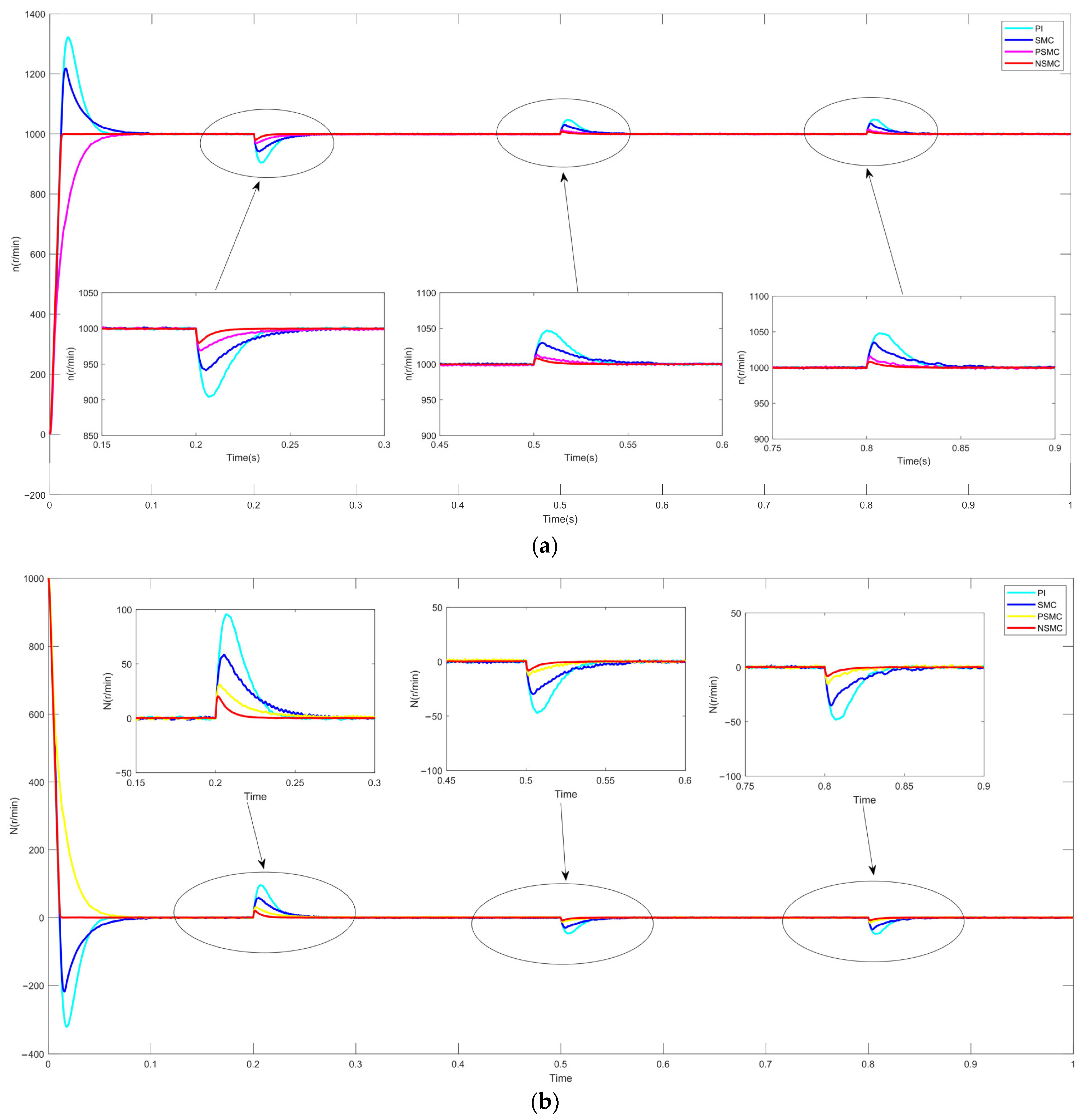
6.2. Multi-Motor Simulation Results

To simulate real-world operating conditions of shaftless printing systems where loads constantly fluctuate, the experimental design implements sequential load variations (no load → heavy load → light load → no load) with the torque parameters specified in Table 3.
The acquired data demonstrate motor performance through
(1)
dynamic response curves under load transitions (Figure 7 and Figure 8),
(2)
rotational speed error analysis (Figure 9),
(3)
synchronization performance analysis between multiple motors (Figure 10 and Figure 11), and
(4)
comparative torque characteristics (Figure 12),
  • comprehensively illustrating system behavior under dynamic load variation scenarios.
Table 3. Load torque under variable operating conditions.
TimeOperating ConditionLoad Torque (M1)TLLoad Torque (M2)TLLoad Torque (M3)TL
0–0.2 sNo load0 N·m 0 N·m0 N·m
0.2–0.5 sHeavy load0 N·m12 N·m10 N·m
0.5–0.8 sLight load0 N·m6 N·m5 N·m
0.8–1 sNo load0 N·m0 N·m0 N·m
Figure 7. Speed diagram of each motor under complex working conditions.
Symmetry 17 00958 g007
Figure 8. Comparison of speed between traditional deviation coupling and improved deviation coupling.
Symmetry 17 00958 g008
Figure 9. (a) Diagram of speed error between motors in traditional deviation coupling. (b) Existing literature scheme motor speed error diagram. (c) Improved deviation coupling speed error diagram between motors.
Symmetry 17 00958 g009aSymmetry 17 00958 g009b
Figure 10. Improved sliding mode control synchronization performance comparison chart.
Symmetry 17 00958 g010
Figure 11. Final solution synchronization performance comparison chart.
Symmetry 17 00958 g011
Figure 12. Torque comparison under complex operating conditions.
Symmetry 17 00958 g012
As illustrated in Figure 8, the enhanced deviation compensation structure (NDCS) achieves better synchronization accuracy than both traditional DCS and prior PDCS approaches, with reduced inter-motor speed discrepancies.
Load disturbance analysis in Figure 9a–c shows that conventional DCS has speed deviation fluctuations up to 35 r/min and 5 r/min during steady operation, and PDCS reaches 11 r/min maximum and 1 r/min during steady operation, whereas NDCS limits deviations to 8 r/min peak and 0.2 r/min during steady operation.
Figure 10 and Figure 11 indicate that classical sliding mode controllers produce substantial speed overshoot, extended settling time during load transients, and significant torque ripple during startup. In contrast, the improved sliding mode controller achieves near-zero overshoot acceleration to rated speed, stable torque output during operation, and minimal settling time under load impacts.
The experimental data demonstrate that the novel coordinated control strategy combining improved sliding mode control with deviation coupling (NSMC+NDCS) achieves 38.7% faster dynamic response and 21.4% enhanced stability metrics in complex operating conditions compared to conventional methods (SMC+DCS) and existing solutions (PSMC+PDCS).
In conclusion, the developed control scheme demonstrates remarkable robustness under nonlinear strong coupling conditions. Practical application in rotogravure presses enhances color registration accuracy while decreasing material waste and energy consumption, fulfilling stringent industrial demands. Therefore, the coordinated control strategy of multi-PMSM for gravure printing machines based on the improved sliding mode controller proposed in this study has an innovative solution.

7. Conclusions

This article takes three permanent magnet synchronous motors as the research object and designs a new type of deviation-coupled synchronous speed compensator. In order to further improve the synchronization performance and anti-interference ability of multiple motors, this article adopts an improved sliding mode control strategy for the current loop and an improved super spiral structure for the speed loop. On this basis, a synchronous control strategy for multi-permanent magnet synchronous motors in a shaftless printing system based on a new sliding mode control was proposed, and three PMSM speed synchronization system simulation models were established in MATLAB (2023 b) for comparative simulation verification. The following conclusions can be drawn from the simulation results:
(1)
Based on the improved sliding mode control, the PMSM deviation coupling control strategy has achieved smooth operation at high speed and high torque. Moreover, the motor has a faster response speed, smaller overshoot, stronger disturbance resistance, better dynamic responsiveness, and improved ability to follow the reference speed.
(2)
The new synchronous speed compensator has better synchronization performance compared to traditional speed compensators and reduces synchronization errors between motors, thereby reducing motor losses and extending their lifespan.
The proposed control strategy demonstrates robust performance in practical applications despite challenges including parameter tuning complexities and discrepancies between simulations and actual conditions. Its exceptional stability under nonlinear, strongly coupled operating conditions significantly enhances printing precision while reducing production costs and defect rates, effectively fulfilling industrial requirements. The shaftless overprinting system’s control mechanism must address compound disturbances like abrupt tension variations and thermal drift. However, the combined output of the sliding mode term q s x 1 α and coupling term K j ε j may approach the physical limitations of drive components.

8. Prospects for Future Work

Future research must strategically integrate cutting-edge developments in control theory (including adaptive sliding mode techniques and distributed architectures), breakthrough enabling technologies (such as TSN networks and FPGA acceleration), and intelligent systems (like digital twins and deep learning models) to comprehensively address the multifaceted challenges in shaftless printing registration control. These interdisciplinary approaches are expected to not only advance printing technology but also create universally applicable theoretical frameworks for multi-motor coordination systems in industrial applications.

Author Contributions

Conceptualization, Y.X. and C.L.; methodology, Y.X.; software, Z.H.; validation, S.S.; formal analysis, C.L.; investigation, C.L.; resources, Z.C.; data curation, Y.X.; writing original draft preparation, Y.X.; writing—review and editing, Y.X., C.L. and Z.C.; supervision, C.L.; project administration, C.L.; funding acquisition, C.L. All authors have read and agreed to the published version of the manuscript.

Funding

This work was supported in part by the Jilin Province Development and Reform Commission Project 2022C045-11, the Jilin Province Science and Technology Department project 20190101018JH, and the Graduate Innovation Program of Beihua University Project 2024054.

Data Availability Statement

The original contributions presented in this study are included in the article. Further inquiries can be directed to the corresponding author.

Conflicts of Interest

The authors declare no conflicts of interest.

References

  1. Wang, Z.; Zhang, H. PI Control Strategy for Electric Vehicle Permanent Magnet Synchronous Motor Based on SVPWM. Intern. Combust. Engine Accessories 2020, 25–30. [Google Scholar]
  2. Zhang, Y.; Shi, Q.; Hu, H.; Cai, S.; Gao, S.; Zhang, Z.; Chen, S.; Wei, C. Design of autonomous flight system for biomimetic flapping wing aircraft based on PID algorithm. South. Agric. Mach. 2024, 134–137. [Google Scholar]
  3. Liu, Y.; Ma, J.; Wu, Q.; He, Z.; Tan, T.; Chen, C. Performance Study of Fractional Order Fuzzy Backstepping Controller for Permanent Magnet Synchronous Motor. Manuf. Technol. Mach. Tool 2024, 1–14. Available online: https://link.cnki.net/doi/10.19287/j.mtmt.1005-2402.2025.04.014 (accessed on 22 April 2025).
  4. Liu, F.; Xie, C. Adaptive Tracking Control of Locomotive PMSM Traction Transmission System. Autom. Technol. Appl. 2024, 1–8. Available online: https://cstj.cqvip.com/Qikan/Article/Detail?id=7108409788&from=Qikan_Search_Index (accessed on 22 April 2025).
  5. Liu, Y.; Yang, J.; Tang, R.; Chen, J. Predefined Time Adaptive Sliding Mode Control for Flexible Space Robots. J. Zhejiang Univ. Eng. Sci. 2024, 1–11. Available online: http://kns.cnki.net/kcms/detail/33.1245.T.20241217.1450.008.html (accessed on 22 April 2025).
  6. Sun, C.; Liu, J.; Li, J. Nonlinear Integral Sliding Mode Variable Structure Control of Electro-Hydraulic Servo System. J. Chongqing Univ. Technol. Nat. Sci. 2024, 1–7. Available online: http://clgzk.qks.cqut.edu.cn/CN/abstract/abstract7228.shtml (accessed on 22 April 2025).
  7. Xi, L.; Ma, J.; Ao, B. Design of Improved Sliding Mode Composite Controller for Permanent Magnet Synchronous Motor. Manuf. Technol. Mach. Tool 2024, 1–11. Available online: https://1951.mtmt.com.cn/cn/article/id/b5946240-b022-4085-81ba-0ac2d9c41a62 (accessed on 22 April 2025).
  8. Jia, L.; Hou, M. Sliding mode control of robotic arm based on adaptive parameter convergence law. Mach. Tools Hydraul. 2024, 51–57. [Google Scholar]
  9. Su, S.; Yue, Y.; Liu, D. Multi motor synchronous control based on improved deviation coupling. Comb. Mach. Tools Autom. Mach. Technol. 2023, 102–105. [Google Scholar]
  10. Xu, D.; Jiang, J.; Liu, A. Research on Multi motor Synchronous Control Strategy of Flexographic Printing Machine. Inf. Technol. Informatiz. 2020, 6, 129–133. [Google Scholar]
  11. Liang, J. Fuzzy Self Regulating Deviation Coupled Multi Motor Synchronous Control; Tianjin University: Tianjin, China, 2017; pp. 123–126. [Google Scholar]
  12. Xiao, H.; Li, K. Multi motor synchronous control strategy with improved adjacent coupling error. Autom. Instrum. 2014, 148–149. [Google Scholar] [CrossRef]
  13. Luo, M.; Wang, J. Adaptive fault-tolerant control of quadcopter unmanned aerial vehicle based on novel sliding mode approach law. Syst. Sci. Technol. 2024, 1–18. Available online: https://sysmath.cjoe.ac.cn/jweb_xtkxysx/CN/lexeme/showArticleByLexeme.do?articleID=54393 (accessed on 22 April 2025).
  14. Huang, H.; Peng, Y.; Huang, X. Improved Adaptive Sensor Less Control of Sliding Mode Permanent Magnet Synchronous Motor Based on SPWM. 2024, pp. 1–11. Available online: https://kns.cnki.net/kcms2/article/abstract?v=v1PGZ9hyqdsmfwKt_wVnpwGXeMA-hqUCJFJ6TqaZJMJV7lNoj4W-SUvGrEfN-vQ7yeA_CbdqsvJ5IFe8SbUdHndgv74e7DRUoEsmDil74UTd81JQPRUYGr7CINjpklu_9D8bsKReYgZpLxptF0zhPOvY9FHwoOW7HKfBtsthwTN9jwDTU3aGmrIRbqukwkFG5jZ91xKsuuk=&uniplatform=NZKPT (accessed on 22 April 2025).
  15. Wang, H.; Zhang, X.; Liu, X. Adaptive Super Spiral Sliding Mode Control of Permanent Magnet Synchronous Motor. Control Eng. 2025, 1–8. [Google Scholar] [CrossRef]
  16. Dong, F. Research on Coupled Synchronous Control of Multi Motor Servo System; Zhejiang University of Technology: Hangzhou, China, 2018; pp. 22–26. [Google Scholar]
  17. Ye, Y.; Peng, F.; Huang, Y. Overview of Multi motor Synchronous Motion Control Technology. J. Electr. Eng. Technol. 2021, 16, 2922–2935. [Google Scholar] [CrossRef]
  18. Gu, X.; Wang, H.; Hu, H. Improving the Coordinated Control of Multiple Motors with Circular Coupling Structure. J. Chang. Univ. Technol. 2022, 115–121. [Google Scholar] [CrossRef]
  19. Alessandro, B.; Lorenzo, C.; Simone, C. Surface Permanent Magnet Synchronous Motors’ Passive Sensor less Control: A Review. Energies 2022, 15, 7747. [Google Scholar]
  20. Zhao, Y.; Wei, C.; Zhang, Z. A Review on Position/Speed Sensor less Control for Permanent-Magnet Synchronous Machine-Based Wind Energy Conversion Systems. IEEE J. Emerg. Sel. Top. Power Electron. 2013, 1, 203–216. [Google Scholar] [CrossRef]
  21. Liu, D.; Song, C.; Du, M. Research on self-coupling PID for multi-driven synchronization control with ring adjacent compensation. Meas. Control 2024, 57, 291–300. [Google Scholar] [CrossRef]
  22. Fardila, M.Z.; Saad, M.; Mubin, M. Robust Speed Control of PMSM Using Sliding Mode Control (SMC)—A Review. Energies 2019, 12, 26–29. [Google Scholar] [CrossRef]
  23. Changlin, Z.; Qunzhang, T.; Chengming, J.; Ming, P.; Hao, H.; Zhiwen, T. Deviation Coupling Control for Multimotor System via Global Fast Terminal Sliding Mode. Control Adv. Math. Phys. 2021, 2021, 9200267. [Google Scholar] [CrossRef]
  24. Mu, Y.; Qi, L.; Sun, M.; Han, W. An Improved Deviation Coupling Control Method for Speed Synchronization of Multi-Motor Systems. Appl. Sci. 2024, 14, 5300. [Google Scholar] [CrossRef]
  25. Zhao, M.; Wang, Q.; Wang, Y.; Dong, Q. Multi-Motor Cooperative Control Strategy for Speed Synchronous Control of Construction Platform. Electronics 2022, 11, 4162. [Google Scholar] [CrossRef]
Figure 1. Structure diagram of shaftless overprint system.
Symmetry 17 00958 g001
Figure 2. Motion state of synovial membrane control.
Symmetry 17 00958 g002
Figure 3. Overall structure of improved sliding mode speed control system. Park: Conversion of coordinates from a two-phase stationary frame αβ to a two-phase synchronous rotating frame dq. Anti-Park: Reinstating the rotating dq frame to a fixed αβ frame through an inverse transformation. Clarke: Transforming a three-phase stationary ABC system into a two-phase stationary αβ coordinate system.
Symmetry 17 00958 g003
Figure 4. Overall structure diagram of deviation coupling control.
Symmetry 17 00958 g004
Figure 5. Structure diagram of the i-th motor compensator after optimization.
Symmetry 17 00958 g005
Figure 6. (a) Output speed diagram of the motor. (b) Motor speed error. (c) Comparison of motor torque. (d) Three-phase current diagram of the motor.
Symmetry 17 00958 g006aSymmetry 17 00958 g006b
Table 1. Parameters of the permanent magnet synchronous motor.
ParameterParameter SizeUnit
Number of pole pairs Pn4
Stator resistance R2.8Ω
Stator d, q-axis inductance Ld Lq8.5mH
Rotor moment of inertia J8.25 × 10−3Kg∙m2
Permanent magnet magnetic flux φf0.175Wb
Damping coefficient B0.001N∙m∙s
Rated load torque TL10N∙m
Sample time Ts1s
DC Voltage Vdc380V
Rated power100Kw
Table 2. Meaning of parameters.
ParameterConnotation
R s The stator phase resistance
u d , u q The d-axis and q-axis voltages
i d , i q The d-axis and q-axis currents
L d , L q The d-axis and q-axis inductances
ψ f The magnetic flux of the permanent magnet
ω r The rotor electrical angular velocity
P n The polar logarithm
T L The load torque
ω m The mechanical angle of the rotor
Disclaimer/Publisher’s Note: The statements, opinions and data contained in all publications are solely those of the individual author(s) and contributor(s) and not of MDPI and/or the editor(s). MDPI and/or the editor(s) disclaim responsibility for any injury to people or property resulting from any ideas, methods, instructions or products referred to in the content.

