Abstract
Friction Stir Welding (FSW) is widely used for high-strength aluminum alloys due to its solid-state bonding, which ensures superior weld quality and service stability. However, thermo-mechanical interactions during welding can induce complex residual stress distributions, compromising joint integrity. Previous studies have primarily focused on thermal load-driven stress evolution, often neglecting mechanical factors such as the shear force generated by the stirring pin. This study develops a three-dimensional thermo-mechanical coupled finite element model based on a moving heat source. The model incorporates axial pressure from the tool shoulder and torque-derived shear force from the stirring pin. A hybrid surface–volumetric heat source is applied to represent frictional heating, and realistic mechanical boundary conditions are introduced to reflect actual welding conditions. Simulations on AA6061-T6 aluminum alloy show that under stable welding, the peak temperature in the weld zone reaches approximately 453 °C. Residual stress analysis indicates a longitudinal tensile peak of ~170 MPa under thermal loading alone, which reduces to ~150 MPa when mechanical loads are included, forming a characteristic M-shaped distribution. Further comparison with a Coupled Eulerian–Lagrangian (CEL) model reveals stress asymmetry, with higher tensile stress on the advancing side. This is primarily attributed to the directional shear force, which promotes greater plastic deformation on the advancing side than on the retreating side. The consistency between the proposed model and CEL results confirms its validity. This study provides a reliable framework for residual stress prediction in FSW and supports process parameter optimization.
1. Introduction
FSW produces heat via frictional contact and plastic deformation at the interface of the rotating tool and the workpiece, resulting in localized thermal softening of the material without melting, thereby achieving metallurgical bonding and offering an efficient and reliable method for joining aluminum alloys [1]. The distinctive solid-state joining mechanism of FSW not only eliminates common issues found in fusion welding—such as porosity and hot cracking—but also significantly mitigates welding distortion and residual stress risks [2]. Recent researchers have attempted to improve the mechanical and tribological properties by introducing ceramic reinforcement phases. Kumar et al. produced aluminum matrix composites by the stir casting technique, and testing findings indicated that the addition of reinforcing phases markedly improves the material’s tensile characteristics and wear resistance [3]. Temperature gradients unavoidably form throughout the FSW process, resulting in residual strains, the magnitude of which is significantly affected by heat input and cooling rate. The downward force from the stirring head and the tangential force produced by frictional stirring are essential in the evolution of stress throughout the FSW process. Due to the symmetrical configuration of the stirring head’s shoulder and pin [4], the distribution of heat input and the consequent residual strains from thermal loading during welding often exhibit a degree of symmetry [5]. In thermo-mechanically linked models, the application of mechanical loads, especially the shear force from the stirring pin, can disturb this equilibrium, resulting in an unequal distribution of residual stress.
During the FSW process, residual stresses are inevitably introduced in the weld joint and surrounding areas due to local frictional heating and material plastic deformation [6]. Typically, residual tensile stresses are concentrated at the center of the weld, while the heat-affected zone (HAZ) tends to develop compressive residual stresses [7], which can critically influence the mechanical behavior, service performance, and durability of the welded structure. Excessive tensile stresses may reduce the fatigue resistance of the weld joint, increasing its susceptibility to crack initiation under cyclic loading, and may also exacerbate stress corrosion cracking—a phenomenon particularly evident in high-strength aluminum alloys [8]. Furthermore, the uneven distribution of residual stresses may cause welding distortion, such as warping, twisting, or shrinkage, thereby affecting assembly precision and overall structural stability. Consequently, the strength, fatigue resistance, and service life of FSW joints are significantly enhanced by the prudent management of residual stresses. Lim [9] and colleagues conducted an investigation into the residual stress distribution during the FSW process and its impact on the mechanical performance of 409 L stainless steel welds. They noted that the central region of the agitated zone exhibited minimal residual stress, as the accumulated tensions were alleviated through dynamic recrystallization. The longitudinal residual stress profile is typically characterized by maximal tensile stresses near the weld line and a lower concentration in the middle, as reported by Jesper et al. [10]. Temperature gradients, welding speed, and cooling rate are among the parameters that regulate the formation of such stresses [11,12,13]. Richter-Trummer [14] conducted an analysis of the impact of clamping force on residual stress distribution and discovered that greater clamping levels result in more uniform and elevated residual stress fields, while lower clamping forces produce diminished and uneven stress patterns. The impact of welding speed, rotational speed, and axial force on stress evolution was investigated by Nie [15] and colleagues. Their findings indicated that residual stress levels are significantly impacted by welding speed and axial pressure, while the impact of rotational speed is relatively negligible.
An increase in welding speed and axial force was shown to raise the residual tensile stress in the weld zone, which may jeopardize the weld’s structural performance and quality. Through experimental investigations and response surface methodology (RSM), Sabry [16] investigated the influence of FSW process parameters on the development of residual stress in AA2024 and AA356-T6 aluminum alloy joints. He also developed predictive models that reflected these findings. The research demonstrated that the reduction of residual stress is facilitated by the appropriate selection of welding parameters, which in turn reduces the risk of fracture and welding distortion. Buglioni [17] and others studied the numerical distribution of residual stresses through experiments and thermomechanical coupled finite element models. The findings revealed that the residual stress magnitudes obtained from both experimental measurements and numerical simulations were consistent. However, the simulation results indicated elevated residual stress levels near the edges of the stirred zone and beyond, and reduced values toward the end of the plate. Moreover, the variation in residual stress with respect to welding speed differed between the two methods.
To accurately predict and analyze the evolution of stress and temperature fields throughout the FSW process, numerical simulation methods are widely applied [18,19,20,21]. This integrated approach not only facilitates a deeper insight into the mechanical property changes occurring during welding but also uncovers the underlying mechanisms responsible for residual stress formation, reduces experimental costs, and provides theoretical guidance for process optimization.
Key techniques in FSW numerical modeling studies include the Arbitrary Lagrangian–Eulerian (ALE) model, the Coupled Euleri–Lagrangian (CEL) model, and the Smoothed Particle Hydrodynamics (SPH) approach. The Finite Element Method (FEM) is widely used. Meyghani et al. [22] applied the ALE approach to FSW simulations by incorporating mathematical formulations to enhance accuracy. Their study indicates that during welding, a sharp increase in heat causes expansion of the shear zone, with temperature peaking rapidly at the initial welding stage and stabilizing during subsequent phases. Similarly, in addition, Myung et al. [23] used the ALE approach to demonstrate that the first thermal spike in the FSW process is mostly attributed to frictional heat produced by sliding at the tool–workpiece contact. The subsequently stabilized temperature is the result of the continuous transition of softened material between adhesive and sliding states. Meyghani et al. [24] further enhanced simulation accuracy by refining the friction model within an Eulerian-based Computational Solid Mechanics (CSM) framework, focusing on the relationship between relative velocity and pressure to better characterize frictional behavior throughout the welding process. Furthermore, Akbari et al. [25] used the CEL model to study the impact of welding speed and tool rotation on temperature and strain distribution during the FSW of AA5083 and AA7075 aluminum alloys. The mechanical properties of the material are ultimately improved under specific welding parameters as a result of the increased temperature and strain, which improves material flow and promotes mixture as the rotation speed increases. Hosseini et al. [26] used the CEL method to study defect formation in underwater stationary shoulder FSW, showing the link between cavity formation and material flow. Experiments confirmed that optimizing welding parameters and tool geometry improves joint performance and reduces defects. Eivani et al. [27] proposed a hybrid model that integrates the Smoothed Particle Hydrodynamics method with the Adaptive Neuro-Fuzzy Inference System to predict the residual stress field during the Friction Stir Welding of AZ91 magnesium alloy. The model’s correctness was validated using ultrasonic testing, and the influence of various welding conditions on residual stress was evaluated. In terms of thermo-mechanical modeling for FSW, Pan et al. [28] developed an SPH-based simulation framework capable of accurately predicting key physical phenomena, including material flow, temperature distribution, grain refinement, microhardness variation, and texture evolution. By comparing with experimental results of AZ31 magnesium alloy, the accuracy and advantages of the SPH method in predicting physical characteristics of the welding process were verified. Furthermore, Bagheri et al. [29] used numerical simulation to explore the effect on FSW. Vibration improved material flow, refined grain structure, reduced defects, and lowered forces and torque, enhancing weld quality and joint performance.
The moving heat source method in FSW finite element simulations simulates the frictional heat produced by the linear motion and rotation of the agitating instrument, using it as a dynamic heat source to predict the temperature field distribution, assuming that all shear actions at the interface during welding are converted into frictional heat [30]. Yang et al. [31] proposed a general heat source model based on tool geometry and interface conditions to simulate the impact of different probe configurations on heat generation and welding behavior. Experimental and simulation results show that increasing the probe area can enhance heat input and promote lateral material flow in the weld zone, thereby optimizing the formation of the plasticized region and improving weld quality. Additionally, Su et al. [32] developed a heat source model derived from tool torque data, which precisely forecasts the thermal response during friction stir welding (FSW). Alhourani et al. [33] successfully reproduced the temperature distribution in friction stir welding (FSW) of thick HDPE plates by using a hybrid heat source model that integrates a moving heat input. To obtain a more accurate prediction of weld temperature fields, this model incorporates both solid-state frictional and viscous flow heat, which is consistent with experimental observations. Their study revealed that the temperature field and heat distribution are markedly affected by the rotating speed of the agitating pin, with increased velocities leading to improved process stability. Furthermore, Yan et al. [34] proposed a transient temperature prediction method by constructing a comprehensive heat source model accounting for both frictional and viscoplastic heat and validated its accuracy through simulations and experiments. Liu et al. [35] introduced an enhanced analytical heat source model, assuming uniform heat flux within the pin volume, which is segmented for individualized flux calculations. Their results demonstrated that the refined model, when incorporating non-uniform volumetric heat flux and tool tilt angle, enables more precise predictions of the thermal cycle and peak temperatures during FSW. Feng et al. [36] formulated an improved heat source model for AZ31 magnesium alloy, emphasizing the influence of welding conditions on maximum temperature. Experimental data confirmed that temperature increases with higher rotation speed or lower welding speed.
Although the aforementioned numerical simulation methods serve as effective tools for analyzing the thermo-mechanical behavior of the FSW process, current studies still present notable limitations in the comprehensiveness of mechanical load modeling. Most existing models simplify the mechanical loading conditions to a single pressure or torque applied at the tool shoulder interface, overlooking the critical influence of the dynamic shear force generated by the probe during penetration and stirring on stress evolution. For example, Wang et al. [37] examined how different FSW procedures affect temperature profiles, residual stress distribution, and structural deformation in Ti62A alloy joints using a three-dimensional thermo-mechanically coupled FEM, but did not incorporate the shear force acting in the probe region, which may contribute to discrepancies between simulated and actual welding deformation curves. Similarly, Miao et al. [38] optimized the shoulder loading parameters using a neural network, where the connection weights and threshold values in a backpropagation (BP) neural network were adjusted via Beetle Swarm Optimization (BSO). Although their model accounted for the effect of axial pressure on the weld profile to enhance stress field accuracy, the role of tangential force was not considered. Additionally, Li et al. [39], through the use of a thermo-mechanically integrated finite element framework, observed that the probe’s action reduces longitudinal residual tensile stress within the weld region and results in an asymmetric residual stress distribution, with the peak stress on the retreating side being lower than that observed on the advancing side. However, their study mainly focused on the heat transfer efficiency and mechanical load of the shoulder, without adequately considering the influence of the probe’s mechanical load on residual stress. Most current studies model only the axial pressure or torque applied at the shoulder region of the tool, overlooking the contribution of the probe’s shear force to stress field evolution. Therefore, a thermo-mechanical coupled modeling method that concurrently considers both the shoulder and probe shear forces is still lacking, making it difficult to fully explain the stress evolution mechanisms during the FSW process.
This study explores the thermo-mechanical coupling mechanism in FSW, incorporating mechanical load factors into the conventional thermal model, taking into account the force characteristics of the shoulder and pin, and offering a more accurate depiction of residual stress distribution. The thermal analysis examines the influence of frictional heat generated by the shoulder on the temperature distribution. The heat-generating areas of the shoulder and agitating pin are considered surface heat sources, and the heat flux density is included in the finite element model. The mechanical analysis takes into account the mechanical constraints in the FSW process, which include the fixture as boundary conditions on the bottom and sides, as well as the downward pressure and shear force on the pin. The results show that the residual stress is reduced in the model considering shear force and axial pressure compared to the pure thermal model. The stress on the advancing side is increased by mechanical loading, while the overall residual stress in the weld zone is reduced. An effective analytical tool for examining the creation mechanism of residual stress in friction stir welding (FSW) was created using numerical simulation to precisely forecast the temperature changes throughout the welding process.
2. Model Description
During the friction stir welding process, when the rotating welding tool is inserted into the workpiece joint with a certain axial pressure, intense friction occurs between the tool and the workpiece surface, generating a significant amount of frictional heat. To maintain welding stability during the process, the workpiece is clamped at both ends by fixtures and supported at the bottom by a backing plate. Boundary conditions for the workpiece are defined in the finite element model, as shown in Figure 1.
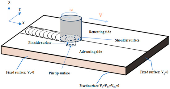
Figure 1.
Schematic diagram of the friction welding process.
The welding procedure can be divided into three stages: the plunging stage, the constant welding stage, and the withdrawal stage. During plunging, the welding tool begins to rotate as it contacts the workpiece surface and applies axial pressure, gradually penetrating the joint region. In this process, frictional heat raises the local material temperature, causing plastic deformation that softens the material and prepares it for the subsequent welding. After entering the steady welding stage, the welding tool moves evenly along the joint line while maintaining rotation. At this point, the generation of frictional heat reaches a steady state, and the axial pressure and rotational speed of the tool remain constant, keeping the material in the welding zone in a state of continuous plastic flow. When the welding reaches its endpoint, the welding tool begins to slowly withdraw from the weld seam. As the tool is withdrawn, the axial pressure gradually decreases, and the temperature in the welding zone also drops accordingly.
This study employs AA6061-T6 as the base material for welding, acknowledging that during the FSW process, the alloy’s properties undergo notable changes with increasing temperature—particularly nonlinear variations in mechanical properties, including strength, hardness, and plasticity. To more accurately simulate material behavior during welding, experimental data on the temperature-dependent variation of material properties are referenced in this study and listed in Table 1.

Table 1.
Temperature-dependent variation of the physicochemical characteristics of AA6061-T6 [40].
3. Finite Element Analysis
To gain deeper insights into the evolution of the temperature field and FSW process, various modeling approaches have been proposed in academia, including the ALE method, CEL method, SPH method, and moving heat source method. As shown in Table 2, each method has distinct characteristics and is suitable for different research objectives and deformation scales. However, while ensuring predictive accuracy, these methods often compromise computational efficiency. The moving heat source method simplifies the description of heat input during welding by defining the geometry, power distribution, and movement path of the heat source, enabling rapid acquisition of temperature distribution and thermal cycle data. This method performs well in welding process optimization and HAZ analysis. However, it generally neglects the mechanical behavior of the material and external loads during welding, making it difficult to accurately predict the formation and evolution of the residual stress field.
Table 2.
Friction stir welding simulation methods.
Numerical simulations were performed utilizing the ABAQUS 2021 software platform to further examine the distribution of the temperature field and the development of residual stress in the friction stir welding process. As shown in Figure 2, this model fully accounts for the thermomechanical interaction mechanisms during welding, with user subroutines DFULX and DLOAD employed to accurately apply the heat source and mechanical loads, thereby enhancing the physical realism and predictive accuracy of the simulation.
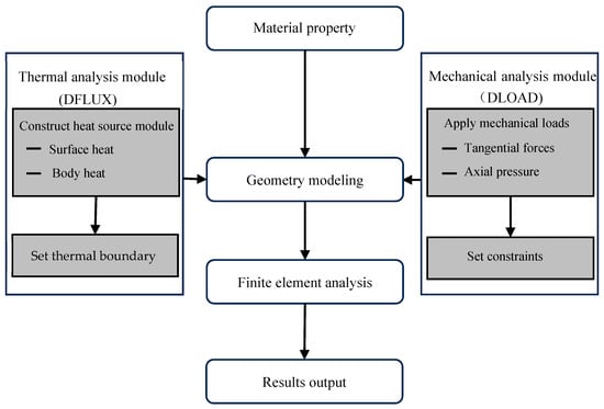
Figure 2.
Simulation flowchart of FSW for AA6061-T6 aluminum alloy.
The heat source model considers the heat flux input resulting from heat creation at both the shoulder and pin of the stirring tool. To enhance the fitting precision of the heat source model, the heat input area is segmented into the contact interface between the shoulder and the workpiece, as well as the region influenced by the stirring pin. In the mechanical analysis, axial pressure and shear force from the stirring tool during welding are applied to simulate the material deformation behavior under thermal-mechanical coupling during the actual processing. In order to guarantee dynamic consistency between the material’s mechanical reaction and temperature field fluctuations, a temperature-dependent material constitutive model is also included in the friction stir process.
To simplify the numerical model, the following assumptions are adopted. A clamping fixture is applied during welding, and in the simulation, it is represented by equivalent boundary conditions, as illustrated in Figure 3. Secondly, the workpiece material is considered isotropic and homogeneous, enabling a uniform distribution of thermal conductivity, mechanical properties, and plastic flow behavior within the numerical model. The dimensions of the workpiece are 120 mm × 120 mm × 3 mm, consisting of two 120 mm × 60 mm × 3 mm plates joined by butt welding.
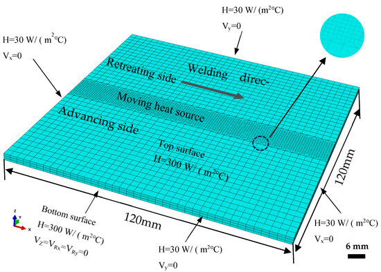
Figure 3.
Geometric model and mesh division of friction stir welding.
The stirring tool used in welding has the following geometrical specifications: a shoulder diameter of 10 mm, a pin diameter of 4 mm, and a pin length of 2.7 mm. Furthermore, two sets of parameters for the welding process were created for comparison. The first set included welding speeds of 80 mm/min, 100 mm/min, and 120 mm/min while maintaining a constant tool rotation speed of 1300 r/min. The second set varied the rotation speed to 900 r/min, 1100 r/min, and 1300 r/min while fixing the welding speed at 100 mm/min. Previous studies on friction stir welding [41] have indicated that overly coarse meshes may reduce computational accuracy, whereas excessively fine meshes can significantly increase computational time. In this study, a transitional mesh is used to ensure efficiency and computational accuracy, accelerating the thermomechanical coupling calculation process. In the mesh transition area, a mesh size of 0.15 mm × 0.1 mm is used, and in the welded region, a mesh size of 0.1 mm × 0.1 mm is used, as shown in Figure 3. The thickness direction is divided into three layers of elements, with a total of 9360 elements. In the finite element model, the thermomechanical coupling is handled using a fully coupled approach. The mesh is divided into hexahedral elements, with the element type selected as C3D8RT.
3.1. Moving Heat Source Model of Friction Stir Welding
Previous studies have indicated that the primary sources of heat generation in the FSW process are the friction between the stirring tool and the workpiece, as well as the material’s plastic deformation during welding [31,32,33]. According to research, the total heat output in FSW may be divided into two parts, as illustrated in Figure 4: the heat generated by plastic deformation in the weld zone and the heat generated by frictional contact between the tool and the workpiece. Frictional heat generated at the tool–workpiece contact is the main source of heat creation during FSW [42]. According to pertinent research, plastic deformation often contributes just a small portion of the overall heat input, whereas frictional heat typically makes up the bulk. As a result, this study uses a heat source model where frictional heat predominates.
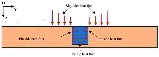
Figure 4.
Schematic diagram of heat generation in friction stir welding.
According to earlier studies [37], the stirring tool’s shoulder and pin are the two main areas in charge of heat dispersion, accounting for around 75% and 25% of the input heat, respectively. As a result, the pin region is regarded as a volumetric heat source, and the shoulder region is considered a surface heat source. The following equation explains how these heat sources are included in the model using a moving heat source approach.
In the equation, QT represents the total welding heat input, MZ(N·m) is the torque of the stirring tool around the z-axis, ω(rad/s) is the angular velocity of the stirring tool, and n(r/s) is the rotational speed of the stirring tool.
Based on friction stir welding’s heat-generating properties, the following hypotheses are made: Initially, it is believed that 95% of the heat is used efficiently during welding. Second, it is anticipated that the rate of heat generation during the welding process is dispersed throughout the stirring pin area and the interface where the tool shoulder contacts the workpiece. Third, the heat flux in the stirring pin area is characterized as a volumetric heat source, whereas the heat flux density on the contact surface between the shoulder and the workpiece is represented as a surface heat source.
In the formula, QS and Qp represent the heat generation power of the shoulder and the stirring pin, respectively; qs(r) and qp(r) are the heat flux densities in the regions of the shoulder and the stirring pin, respectively; r is the distance from the integration point to the center axis of the stirring head, R1 is the radius of the shoulder, R0 is the radius of the stirring pin, h is the length of the stirring pin and z is the coordinate in the thickness direction of the welded plate.
For the heat source model in friction stir welding, the equation for the nonlinear transient heat transfer process can be expressed as follows [43]:
In this equation, T denotes temperature, t signifies time, qpl indicates the heat produced by deformation caused by plastic, ρ represents substance density, and cp refers to specific heat capacity. As this model omits material flow, qpl is simplified to the heat flux quantity of the stirring instrument.
When a temperature gradient exists between two or more bodies, or within a single body, heat is transferred through molecular and atomic collisions. Consequently, the temperature field’s formation is influenced by the surrounding environment in addition to the workpiece’s properties during welding. The distribution of the temperature field is significantly predicted by the definition of thermal boundary conditions in numerical simulations. The efficacy of heat transfer between the workpiece surface and adjacent media is determined by boundary heat transfer conditions, as the thermal response of the material during welding is influenced by both internal heat sources and the heat exchange with the external environment. Different thermal boundary environments may result in significant changes in temperature gradients, cooling rates, and the associated thermal stress behavior. For instance, Khalaf et al. [44] compared the differences in heat conduction and residual stress evolution between conventional FSW in air and underwater FSW (UFSW) through experimental measurements and CFD simulations. They found that when water is used as the cooling medium, heat dissipates more rapidly in the weld zone, resulting in a lower peak temperature and a reduction in residual stress levels. This phenomenon suggests that the temperature field and the resulting stress state can be substantially influenced by a simple modification to the boundary heat exchange environment, even under identical heat input conditions. The heat exchange boundary conditions between the workpiece and the surrounding environment must be considered in order to accurately describe this process. The primary thermal exchanges during welding occur between the upper surface of the workpiece and the air, as well as between the lower surface and the supporting plate.
For the upper surface and surrounding areas of the workpiece in contact with air, convective heat transfer with the air should be considered, as described in ref. [43]
For the upper surface and surrounding areas of the workpiece in contact with air, convective heat transfer with the air should be considered, as described in ref. [43]
In Equations (7) and (8), σb denotes the Stefan–Boltzmann constant, valued at 5.67 × 10⁻⁸ W·m−2 K−4, and ε represents the emissivity, T0 is the ambient temperature, while htop and hbottom are the heat transfer coefficients for the top and bottom surfaces, respectively.
Heat dissipation during welding primarily occurs through three mechanisms: conduction, convection, and radiation. To commence the welding procedure, an initial room temperature of 25 °C is assigned under actual thermal boundary conditions. The convective heat transfer coefficient for the top surface exposed to air is set to 30 W/(m2·°C) when the interactions and boundary conditions for heat conduction and radiation are established, as illustrated in Figure 3. This coefficient characterizes heat exchange with the surrounding environment. Meanwhile, the coefficient is specified as 300 W/(m2·°C) for the interface between the welded component and the supporting plate, where the convective intensity is higher.
3.2. Mechanical Modeling
The welding process’s impact on the mechanical constraints of the workpiece, as well as the discharge of these constraints during cooling, must be completely taken into account in account in mechanical analysis. Mechanical limitations are applied during welding by limiting the workpiece’s side and bottom surface movement. In the cooling stage, these constraints need to be released to allow the workpiece to deform freely, thus triggering changes in stress and strain. In the simulation, the mechanical constraints are equivalent to boundary conditions. As shown in Figure 3, the side surfaces of the workpiece are set as Vx = 0 and Vy = 0, while the bottom surface constraints are equivalent to restricting movement in the z-direction and rotation in the x and y directions, i.e., Vz = VRx = VRy = 0. The force balance on any volume is as follows [45]:
σij denotes the stress tensor, Fi represents the body force intensity in N∙m−3, ai is approximately 0 for material acceleration (m∙s−2), and ρ signifies the material density (kg∙m−3). The incremental technique is employed for analyzing spatial thermo-elastoplastic issues. This procedure assumes that the material’s deformation behavior adheres to the von Mises yield requirement and its associated flow rules. The correlation among stress rate, strain rate, time, and temperature is as follows [45]:
E, G, v, and α represent Young’s modulus, shear modulus, Poisson’s ratio, and the coefficient of thermal expansion (K−1), are components of the deviatoric stress. λ is the plastic flow factor, where λ = 0 or σe ≤ σy corresponds to elastic deformation, and λ > 0 or σe > σv corresponds to plastic deformation. σy is the yield stress of the material, is the von-Mises effective stress.
Mechanical Load Analysis
During the simulation of the moving heat source in FSW, a thermo-mechanical coupling mechanism is introduced. The model accounts for mechanical loads exerted by the stirrer on the material throughout the welding process. These loads include a surface force applied to the shoulder, a body force induced by the downward pressure on the shoulder, and another body force generated by the stirring pin. The shoulder surface load simulates the external vertical pressure acting on the stirrer during welding, mainly applied to the contact interface to reflect the actual stress state. In order to simulate shear forces brought on by rotating friction, the body load is applied to both the shoulder and pin areas. This captures the intricate relationship between the tool and the material as well as its mechanical reaction. As shown in Figure 5, the mechanical pressure and frictional shear force distributions are incorporated in the model. The working torque is simplified as shear stress along the tool–material interface, while the axial force is characterized as a homogeneous surface pressure. The vertical distribution pressure is denoted as follows [37]:
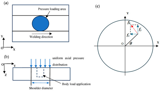
Figure 5.
Schematic of the shoulder loading. (a) Downward pressure on the shoulder, (b) Loading of downward pressure and body load in the model, (c) Tangential force.
Fz is the downward pressure on the shoulder.
Since torque is the cumulative moment generated by the force at each point on the stirrer surface relative to the center of rotation, the torque effect can be expressed by introducing the tangential force at each point on the stirrer surface [39,46]. Figure 5c illustrates the rotational shear force at the interface between the agitating instrument and the workpiece.
As shown in Figure 6a, during the steady-state welding stage, the frictional force on the lateral surface of the tool is equal to the integral of the frictional force per unit area. In cylindrical coordinates, the infinitesimal volume element on the lateral surface of the stir tool is given by
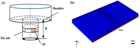
Figure 6.
(a) Infinitesimal element on the stir pin sidewall. (b) Schematic diagram of path 1.
The frictional shear force on this infinitesimal element is
The infinitesimal torque generated by this force is
The torque on the stir pin, M1 is given by
As shown in Figure 5c, the tangential force is resolved into components in the X and Y directions, denoted as fx and fy, respectively [34]:
The frictional shear force component on the stir pin is
M1 represents the torque on the stir pin.
The frictional torque at the shoulder region of the tool can be obtained by integrating the frictional moment over the contact surface, and the torque on the shoulder, M1, is given by
Thus, the frictional force per unit area in the shoulder region, fa, is given by
Based on a thermo-mechanically coupled finite element model, this study attempts to simultaneously incorporate tangential body forces from both the shoulder and the stir pin into the simulation. The shear force in the stir pin region is applied in the form of a body force, derived from torque decomposition formulas.
3.3. CEL Model
The CEL method has been widely applied in previous studies for the numerical simulation of FSW and has demonstrated high accuracy in predicting temperature and stress fields, particularly showing good consistency in capturing material flow trajectories, residual stress distribution, and defect evolution [25,47,48].
The temperature distribution and residual stress evolution during FSW are predicted with optimistic results by the thermo-mechanically coupled finite element model devised in this study. On the other hand, its modeling approach, which is predicated on a moving heat source, fails to explicitly consider the material’s plastic flow behavior during welding. In order to resolve this constraint, the CEL method is implemented. The physical validity and applicability of the moving heat source framework are assessed in this study by contrasting the residual stress results from both modeling approaches under the assumption of negligible material flow.
In the CEL method, the workpiece is defined as an Eulerian body and the tool as a Lagrangian body [49], allowing the material to flow within a fixed mesh in response to external loading, thereby effectively avoiding the mesh distortion problems encountered in conventional Lagrangian methods when dealing with severe plastic deformation. This approach is particularly suitable for describing the large-strain, shear, and disturbed flow behaviors of welding materials in the FSW process.
A numerical model that is based on CEL is developed on the ABAQUS 2021 platform in this investigation, adopting the same geometric dimensions, welding path, boundary conditions, heat dissipation parameters, and process settings as those in the previously developed moving heat source model. The workpiece material is AA6061-T6 aluminum alloy, consistent with the prior setup. Unlike the idealized heat input in the previous model, the thermal energy here is derived from both frictional and plastic deformation heating at the tool–workpiece interface.
The welding speed is set to 100 mm/min, and the tool rotation speed is set to 1300 r/min. The welding process is divided into plunge, steady-state welding, and retraction stages, with the entire sequence of temperature rise, plastic zone evolution, and cooling shrinkage fully simulated. As shown in Figure 7, the Eulerian region uses an Eulerian mesh with EC3D8R elements, and the mesh density is refined to 0.5 mm in the central weld zone to enhance accuracy. The tool is modeled using Lagrangian C3D8R elements.
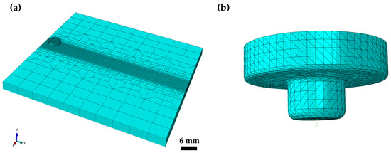
Figure 7.
CEL-based FSW model. (a) Assembly configuration; (b) Stirring tool geometry.
The residual stress distribution obtained from the CEL model will be compared in detail with that from the thermo-mechanically coupled heat source model in Chapter 4. The CEL simulation results serve as a reference standard that incorporates material flow effects, providing support for evaluating the predictive capability and applicability of the heat source model developed in this study for engineering applications.
3.4. Future Research Outlook
The following is a potential direction for future research: First, experimental measurements can be incorporated for quantitative validation of the simulation results to enhance the credibility of the model. In addition to thermo-mechanical effects, microstructural evolution during welding may also play a critical role in the formation of residual stress. For instance, studies have shown that in 6082 aluminum alloys subjected to Friction Stir Drilling followed by T6 heat treatment, precipitation hardening and grain growth induced by heat treatment significantly alter the mechanical response of the material, thereby affecting its residual stress state [50].
Furthermore, in high-manganese austenitic steels, variations in strain rate not only affect the yield strength of the material but also significantly influence the twin volume fraction and dynamic strain aging (DSA) behavior, thereby altering the plastic deformation path and internal stress distribution [51]. These microstructural mechanisms offer a deeper physical understanding of stress evolution in FSW. Future models may consider incorporating twinning and subgrain behavior into a coupled thermo-mechanical-microstructural framework to further enhance prediction accuracy.
4. Results and Discussion
4.1. Temperature Distribution Analysis
In this section, a fully coupled thermal–mechanical analysis is conducted. During welding, both the temperature field and the mechanical loading from the stirring head are applied simultaneously. Heat flux is introduced into the finite element model using a moving heat source formulation (see Formulas (4) and (5)), while the axial force and tangential load are implemented according to Formulas (12)–(14). Predictions are made for temperature and stress distributions throughout the aluminum alloy welding process. Figure 8 illustrates the temperature profile on the welded plate surface during various stages—heat source movement, steady welding, and cooling. The simulation shows that the temperature field across the weld exhibits a symmetric pattern. However, the backside of the shoulder heat source reaches a higher temperature than the front. This is because, as the heat source progresses, the rear side remains exposed to heat for a longer duration, whereas the front side experiences a shorter thermal contact period. As a result, insufficient conduction time to the front limits heat transfer, causing the rear to accumulate more energy and reach a relatively higher temperature.
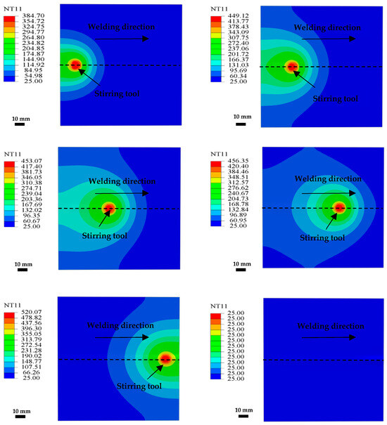
Figure 8.
Temperature field distribution of 6061 aluminum alloy in friction stir welding.
From Figure 8, the temperature distribution on the welded surface at the end of welding shows a peak of 520 °C, which exceeds the temperature observed during steady-state welding. This is primarily because, during the process, frictional heat accumulates in the weld zone, causing a rapid temperature rise over a short duration. At this point, the local temperature remains elevated prior to cooling, as heat dissipation is not yet complete.
In order to analyze the spatial temperature distribution during welding, a cross-section at the very center of the welded plate was chosen. Under a welding speed of 100 mm/min and a rotation rate of 1300 r/min, Figure 9 depicts the temperature field at this section. The weld center experiences a temperature apex of approximately 450 °C, and the temperature progressively decreases on both sides, exhibiting a symmetrical pattern that is consistent with the trends reported in [16]. The primary cause of this behavior is the stable heat input that is the result of the symmetric motion of the heat source along the joint line, in conjunction with the intense friction generated by the stir tool in the central weld zone. The weld center is the first area to be directly affected by the heat source, and the accumulation of local frictional heat and plastic deformation heat is more pronounced. Consequently, the highest temperature zone is formed. The temperature rise rate and peak temperature of the material located further away from the heat source are comparatively lower due to the shortened heating duration. This results in a typical symmetric gradient temperature field.
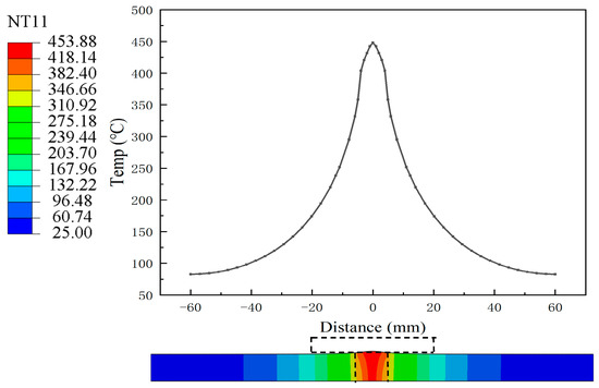
Figure 9.
Simulated temperature field results during steady-state welding.
4.2. Influence of Process Parameters on Residual Stress
The distribution of residual tension in both the weld and heat-affected zone is directly influenced by process parameters during FSW, which in turn affects the level of heat input. To examine how welding speed and tool rotation rate impact stress evolution, two sets of comparative simulations were conducted using the previously established thermo-mechanically coupled model. The corresponding results are presented in Figure 10.
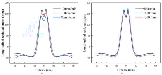
Figure 10.
(a) Residual stress distribution at different welding speeds; (b) Residual stress distribution at different rotation speeds.
The residual stress levels are substantially influenced by the welding pace, as illustrated in Figure 10a. The longitudinal residual stress increases as the welding speed increases when the rotation rate is fixed. The resulting stress distribution exhibits a distinct “M”-shaped pattern, which aligns with findings from prior studies [22,52]. This behavior is primarily due to reduced contact time per unit length as the tool traverses more quickly. Insufficient material softening and reduced heat input in the weld zone are the consequences of limited frictional heating under these circumstances. Consequently, the partially plasticized aluminum alloy offers greater resistance to the forward motion of the stir pin. This results in larger temperature gradient differences across the material, thereby inducing higher longitudinal residual tensile stresses. Furthermore, the results suggest that the longitudinal residual stress field region becomes increasingly constrictive as the welding speed increases. This is due to the fact that the effective heat input range is reduced by higher travel velocities, which results in a smaller lateral extent of the elevated temperature zone. Sun et al. [53] also reported a comparable trend.
Increases in the rotation speed of the stir tool have a comparatively minor impact on residual stress when the welding speed remains constant, as illustrated in Figure 10b. This finding is in agreement with the findings reported in [15,54], suggesting that the primary factor influencing the magnitude of longitudinal residual stress is the variation in welding speed.
4.3. Effect of Different Mechanical Load Combinations on Residual Stress
The material’s non-uniform thermal expansion and contraction, which are predominantly caused by temperature gradients, are the primary causes of residual tension formation in FSW. These gradients induce thermal strain in the weld zone, ultimately leading to stress accumulation. Figure 11 illustrates the longitudinal residual stress distribution along Path 1 at the weld surface, comparing three simulation approaches, as follows:
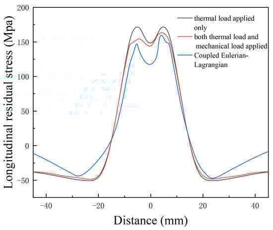
Figure 11.
Comparison of longitudinal residual stress under different simulation methods.
- (1)
- Using only a moving heat source.
- (2)
- Combining the heat source with axial–shear forces from the tool.
- (3)
- Adopting the CEL method with material flow considered.
As shown in Figure 11, notable longitudinal tensile stress appears near the weld center, while compressive stress is present in surrounding regions. This behavior mainly stems from temperature differentials between the weld and adjacent areas, where the contraction of the hotter weld zone is restricted by cooler material nearby. Such constraints induce the development of residual tensile stress within the central zone.
The longitudinal tensile stress in the weld region is characterized by a distinct symmetry and a double-peak distribution in the shape of an “M”, with the peak values being concentrated at the margins of the HAZ. This phenomenon mainly results from the gradual release of constraints on the weldment, causing the boundary of the HAZ to lose its restriction on the material, thereby limiting recovery and leading to the accumulation of maximum longitudinal residual stress at the HAZ edges, which further causes a depression in the weld center. This trend is consistent with the “M”-shaped residual stress distribution observed in dissimilar aluminum alloys with varying welding parameters by Sonne et al. [55], and the stress magnitudes are comparable to those reported by Liu et al. [56].
As shown in Figure 11, the peak longitudinal tensile stress is approximately 170 MPa when only thermal loading is considered. After introducing mechanical loading, the peak decreases to around 150 MPa. In the CEL model that accounts for material flow, the peak stress on the advancing side is around 160 MPa, slightly lower on the retreating side. A comparison between longitudinal residual stress results—obtained using only a moving heat source and those incorporating the tool’s axial pressure and shear force—shows that except in regions directly influenced by the tool, the differences remain minimal. Within the weld zone, tensile stress induced solely by thermal loading is notably higher than when both axial force and shear are considered. Furthermore, the CEL model yields stress magnitudes more consistent with those predicted under combined mechanical and thermal conditions. Additionally, a stress asymmetry is observed between the advancing and retreating sides, which is consistent with the results of He et al. [57] found consistent results.
To better visualize the fundamental differences among the three modeling approaches used in this study, Table 3 summarizes the characteristics of the three models and compares their residual stress responses. For the pure thermal load case, the heat source model is symmetric with respect to the welding direction, as the residual stress generation in this model considers only temperature-induced effects, and the heat generation is distributed symmetrically along the weld axis. Consequently, the longitudinal residual stress disparity between the advancing and retreating sides is negligible when solely the moving heat source is taken into account. Therefore, the residual stress distribution induced purely by thermal loading is essentially symmetric.
Table 3.
Comparison of the characteristics and residual stress performance of three modeling approaches in FSW.
However, when axial pressure and torque are applied, the weld zone exhibits asymmetric residual stress. In particular, the maximal tension is consistently higher on the advancing side when both the axial and shear forces of the instrument and a moving heat source are considered. This occurs because, although the tool’s torque produces a circumferentially uniform shear force, its mechanical effect differs across the two sides. On the advancing side, the shear component aligns with the tool’s travel direction, while on the retreating side, it acts in the opposite direction (see Figure 5). As a result, mechanical stirring is significantly more intense on the advancing side. CEL simulation results further confirm that nodal stress values are greater on the advancing side. The underlying reason is that under the effect of torque, the advancing side experiences more severe plastic deformation, resulting in higher residual stress in that region.
4.4. Analysis of Error Sources and Model Limitations
The heat source model considers the distribution of heat input between the shoulder and pin as uniform and implies a fixed ratio. It neglects the effects of actual tool–workpiece contact conditions and the dynamic variation of friction coefficients on the temperature field, which may result in an overestimation or underestimation of local heat generation. In addition, real stir pins typically possess tapered geometries and threaded features, which influence the contact area and friction path with the material, thereby affecting the location and intensity of frictional heat generation. The assumption of axially uniform frictional and plastic deformation heat may result from the simplification of the agitate instrument as a cylindrical shape in the model. Regarding boundary conditions, the fixture effect is simplified as a fixed constraint, without taking into account the fixture’s and the workpiece’s real contact and heat conduction, which might have an impact on the redistribution and release of stress during thermal expansion and contraction.
5. Conclusions
The author of this research suggested a technique that takes into consideration the tool’s axial shoulder and pin in addition to thermal and mechanical stresses. This method examines the temperature field distribution and residual stress development of 6061 aluminum alloy by numerical modeling, taking into account the impacts of tangential force and shoulder pressure.
- The temperature distribution in the weld zone shows distinct symmetry when friction stir welding is used. The tool’s peak temperature in the steady-state phase is 453 °C, and heat builds up progressively toward the back.
- The temperature gradient is closely correlated with the longitudinal residual tension that is generated during welding. The weld center exhibits a pronounced tensile stress, whereas compressive stress is observed in regions that are further from the weld area.
- Compared to the pure thermal load case, the residual stress distribution under thermal-mechanical coupling has undergone significant changes. Especially on the advancing side, under the effect of shear force, the material undergoes more intense plastic deformation, leading to more pronounced stress peaks.
- The maximal temperature in friction stir welding is between 80% and 90% of its melting point, as indicated by the numerical simulation results.
- Building upon conventional thermo-mechanical coupling models, this study further attempts to incorporate the mechanical effect of shear force generated by the stir pin, with the aim of providing a more comprehensive description of the evolution of residual stress during the FSW process. The simulation results indicate that this method offers valuable insights into the asymmetry of residual stress distribution in the weld region, which may contribute to a deeper theoretical basis for residual stress control.
Author Contributions
Methodology, T.Y. and H.J.; Software, Z.M.; Formal analysis, J.Z.; Resources, X.W.; Writing—original draft, T.Y.; Writing—review & editing, H.J.; Visualization, X.L.; Project administration, H.J.; Funding acquisition, H.J. All authors have read and agreed to the published version of the manuscript.
Funding
This work was supported by the National Natural Science Foundation of China (No. 12002078), the Fundamental Research Funds for the Central Universities (No. 2572022BG03), and the China Postdoctoral Science Foundation (No. 2023M740559).
Data Availability Statement
The raw data supporting the conclusions of this article will be made available by the authors on request.
Conflicts of Interest
The authors declare no conflict of interest.
References
- Ahmed, M.M.Z.; El-Sayed Seleman, M.M.; Fydrych, D.; Çam, G. Friction Stir Welding of Aluminum in the Aerospace Industry: The Current Progress and State-of-the-Art Review. Materials 2023, 16, 2971. [Google Scholar] [CrossRef]
- Gangwar, K.; Ramulu, M. Friction stir welding of titanium alloys: A review. Mater. Des. 2018, 141, 230–255. [Google Scholar] [CrossRef]
- Hewidy, A.M.; Sabry, I. Mechanical and tribological characteristics of stir-casting Al2O3-SiC-Gr/Al6063 hybrid composite. J. Egypt. Soc. Tribol. 2024, 21, 24–38. [Google Scholar] [CrossRef]
- Rajendran, C.; Srinivasan, K.; Balasubramanian, V.; Balaji, H.; Selvaraj, P. Effect of tool tilt angle on strength and microstructural characteristics of friction stir welded lap joints of AA2014-T6 aluminum alloy. Trans. Nonferrous Met. Soc. China 2019, 29, 1824–1835. [Google Scholar] [CrossRef]
- Riahi, M.; Nazari, H. Analysis of transient temperature and residual thermal stresses in friction stir welding of aluminum alloy 6061-T6 via numerical simulation. Int. J. Adv. Manuf. Technol. 2011, 55, 143–152. [Google Scholar] [CrossRef]
- Zhang, T.; Ji, H.; Xu, D.; Yin, X.; Wei, H.; Sun, Z.; Liu, C. A hybrid shoulder to achieve a significant improvement in tensile strength and fatigue performance of friction stir welded joints for Al–Mg–Si alloy. J. Mater. Res. Technol. 2023, 27, 2280–2291. [Google Scholar] [CrossRef]
- Pouget, G.; Reynolds, A.P. Residual stress and microstructure effects on fatigue crack growth in AA2050 friction stir welds. Int. J. Fatigue 2008, 30, 463–472. [Google Scholar] [CrossRef]
- Sabry, N.; Stroh, J.; Sediako, D. Characterization of microstructure and residual stress following the friction stir welding of dissimilar aluminum alloys. CIRP J. Manuf. Sci. Technol. 2023, 41, 365–379. [Google Scholar] [CrossRef]
- Lim, Y.S.; Kim, S.H.; Lee, K.J. Effect of residual stress on the mechanical properties of FSW joints with SUS409L. Adv. Mater. Sci. Eng. 2018, 2018, 9890234. [Google Scholar] [CrossRef]
- Hattel, J.H.; Sonne, M.R.; Tutum, C.C. Modelling residual stresses in friction stir welding of Al alloys—A review of possibilities and future trends. Int. J. Adv. Manuf. Technol. 2015, 76, 1793–1805. [Google Scholar] [CrossRef]
- He, J.; Ling, Z.; Li, H. Effect of tool rotational speed on residual stress, microstructure, and tensile properties of friction stir welded 6061-T6 aluminum alloy thick plate. Int. J. Adv. Manuf. Technol. 2016, 84, 1953–1961. [Google Scholar] [CrossRef]
- Peel, M.; Steuwer, A.; Preuss, M.; Withers, P.J. Microstructure, mechanical properties and residual stresses as a function of welding speed in aluminium AA5083 friction stir welds. Acta Mater. 2003, 51, 4791–4801. [Google Scholar] [CrossRef]
- Campanelli, S.; Casalino, G.; Casavola, C.; Moramarco, V. Analysis and comparison of friction stir welding and laser assisted friction stir welding of aluminum alloy. Materials 2013, 6, 5923–5941. [Google Scholar] [CrossRef]
- Richter-Trummer, V.; Suzano, E.; Beltrão, M.; Roos, A.; Dos Santos, J.F.; De Castro, P.M.S.T. Influence of the FSW clamping force on the final distortion and residual stress field. Mater. Sci. Eng. A 2012, 538, 81–88. [Google Scholar] [CrossRef]
- Nie, L.; Wu, Y.X.; Gong, H. Prediction of temperature and residual stress distributions in friction stir welding of aluminum alloy. Int. J. Adv. Manuf. Technol. 2020, 106, 3301–3310. [Google Scholar] [CrossRef]
- Sabry, I. Exploring the effect of friction stir welding parameters on the strength of AA2024 and A356-T6 aluminum alloys. J. Alloys Metall. Syst. 2024, 8, 100124. [Google Scholar] [CrossRef]
- Buglioni, L.; Tufaro, L.N.; Svoboda, H.G. Thermal cycles and residual stresses in FSW of aluminum alloys: Experimental measurements and numerical models. Procedia Mater. Sci. 2015, 9, 87–96. [Google Scholar] [CrossRef]
- Zina, N.; Zahaf, S.; Bouaziz, S.A.; Brahami, A.; Kaid, M.; Chetti, B.; Najafi Vafa, Z. Numerical simulation on the effect of friction stir welding parameters on the peak temperature, Von Mises stress, and residual stresses of 6061-T6 aluminum alloy. J. Fail. Anal. Prev. 2019, 19, 1698–1719. [Google Scholar] [CrossRef]
- Salih, O.S.; Ou, H.; Sun, W. Heat generation, plastic deformation and residual stresses in friction stir welding of aluminium alloy. Int. J. Mech. Sci. 2023, 238, 107827. [Google Scholar] [CrossRef]
- Geng, P.; Morimura, M.; Wu, S.; Liu, Y.; Ma, Y.; Ma, N.; Aoki, Y.; Fujii, H.; Ma, H.; Qin, G. Prediction of residual stresses within dissimilar Al/steel friction stir lap welds using an Eulerian-based modeling approach. J. Manuf. Process. 2022, 79, 340–355. [Google Scholar] [CrossRef]
- Salloomi, K.N.; Al-Sumaidae, S. Coupled Eulerian–Lagrangian prediction of thermal and residual stress environments in dissimilar friction stir welding of aluminum alloys. J. Adv. Joining Process. 2021, 3, 100052. [Google Scholar] [CrossRef]
- Meyghani, B.; Awang, M.; Wu, C.S. Finite element modeling of friction stir welding (FSW) on a complex curved plate. J. Adv. Joining Process. 2020, 1, 100007. [Google Scholar] [CrossRef]
- Myung, D.; Noh, W.; Kim, J.H.; Kong, J.; Hong, S.T.; Lee, M.G. Probing the mechanism of friction stir welding with ALE based finite element simulations and its application to strength prediction of welded aluminum. Met. Mater. Int. 2021, 27, 650–666. [Google Scholar] [CrossRef]
- Meyghani, B. A modified friction model and its application in finite-element analysis of friction stir welding process. J. Manuf. Process. 2021, 72, 29–47. [Google Scholar] [CrossRef]
- Akbari, M.; Asiabaraki, H.R.; Aliha, M. Investigation of the effect of welding and rotational speed on strain and temperature during friction stir welding of AA5083 and AA7075 using the CEL approach. Eng. Res. Express 2023, 5, 025012. [Google Scholar] [CrossRef]
- Hosseini, A.; Arezoudar, A.F. Modified CEL method for determination of defect formation mechanism in underwater stationary shoulder FSW based on softened pressure-overclosure contact relationship. Forces Mech. 2024, 17, 100296. [Google Scholar] [CrossRef]
- Eivani, A.R.; Vafaeenezhad, H.; Jafarian, H.R.; Zhou, J. A novel approach to determine residual stress field during FSW of AZ91 Mg alloy using combined smoothed particle hydrodynamics/neuro-fuzzy computations and ultrasonic testing. J. Magnes. Alloy. 2021, 9, 1304–1328. [Google Scholar] [CrossRef]
- Pan, W.; Li, D.; Tartakovsky, A.M.; Ahzi, S.; Khraisheh, M.; Khaleel, M. A new smoothed particle hydrodynamics non-Newtonian model for friction stir welding: Process modeling and simulation of microstructure evolution in a magnesium alloy. Int. J. Plast. 2013, 48, 189–204. [Google Scholar] [CrossRef]
- Bagheri, B.; Abdollahzadeh, A.; Abbasi, M.; Kokabi, A.H. Numerical analysis of vibration effect on friction stir welding by smoothed particle hydrodynamics (SPH). Int. J. Adv. Manuf. Technol. 2020, 110, 209–228. [Google Scholar] [CrossRef]
- Frigaard, Ø.; Grong, Ø.; Midling, O.T. A process model for friction stir welding of age hardening aluminum alloys. Metall. Mater. Trans. A 2001, 32, 1189–1200. [Google Scholar] [CrossRef]
- Yang, Z.; Wang, Y.; Domblesky, J.P.; Li, W.; Han, J. Development of a heat source model for friction stir welding tools considering probe geometry and tool/workpiece interface conditions. Int. J. Adv. Manuf. Technol. 2021, 114, 1787–1802. [Google Scholar] [CrossRef]
- Su, H.; Chen, J.; Wu, C. A heat source model for dissimilar Al/Cu friction stir welding process based on tool torque measurement. Int. J. Adv. Manuf. Technol. 2024, 130, 4621–4634. [Google Scholar] [CrossRef]
- Alhourani, A.; Sheikh-Ahmad, J.; Almaskari, F.; Khan, K.; Deveci, S.; Barsoum, I. Thermal modeling of friction stir welding of thick high-density polyethylene plates. J. Mater. Res. Technol. 2024, 28, 4186–4198. [Google Scholar] [CrossRef]
- Yan, F.; Zhang, Y.; Mi, S. A dynamic prediction method of transient temperature in friction stir welding process. Measurement 2022, 200, 111632. [Google Scholar] [CrossRef]
- Liu, X.; Yu, Y.; Yang, S.; Liu, H. A Modified Analytical Heat Source Model for Numerical Simulation of Temperature Field in Friction Stir Welding. Adv. Mater. Sci. Eng. 2020, 2020, 4639382. [Google Scholar] [CrossRef]
- Feng, S.; Liu, Z.; Xin, R. Simulation of Friction Stir Welding of AZ31 Mg Alloys. Materials 2024, 17, 4974. [Google Scholar] [CrossRef] [PubMed]
- Wang, B.; Zhu, P.; Cao, Y.; Zhou, L.; Xue, P.; Wu, L. Effects of different friction stir welding processes on residual stress and deformation of Ti62A alloy joints. J. Mater. Res. Technol. 2023, 26, 6096–6107. [Google Scholar] [CrossRef]
- Jin, T.; Miao, P.; Cui, X.; Wang, J. Intelligent optimization of non-rigidly supported stationary shoulder friction stir welding parameters. Adv. Mech. Eng. 2024, 16, 16878132241235519. [Google Scholar] [CrossRef]
- Li, T.; Shi, Q.Y.; Li, H.K. Residual stresses simulation for friction stir welded joint. Sci. Technol. Weld. Join. 2007, 12, 664–670. [Google Scholar] [CrossRef]
- Chauhan, P.; Jain, R.; Pal, S.K.; Singh, S.B. Modeling of defects in friction stir welding using coupled Eulerian and Lagrangian method. J. Manuf. Process. 2018, 34, 158–166. [Google Scholar] [CrossRef]
- Jiang, H.; Man, Z.; Guo, Z.; Feng, W.; Yang, Z.; Lei, Z.; Bai, R.; Yan, S.; Cheng, B. Determination of residual stress field in laser cladding using finite element updating method driven by contour deformation. Opt. Laser Technol. 2024, 179, 111371. [Google Scholar] [CrossRef]
- Akbari, M.; Aliha, M.R.M.; Berto, F. Investigating the role of different components of friction stir welding tools on the generated heat and strain. Forces Mech. 2023, 10, 100166. [Google Scholar] [CrossRef]
- Selvaraj, M.; Murali, V.; Koteswara Rao, S.R. Thermal model for friction stir welding of mild steel. Multidiscip. Model. Mater. Struct. 2013, 9, 49–61. [Google Scholar] [CrossRef]
- Khalaf, H.I.; Al-Sabur, R.; Abdullah, M.E.; Kubit, A.; Derazkola, H.A. Effects of underwater friction stir welding heat generation on residual stress of AA6068-T6 aluminum alloy. Materials 2022, 15, 2223. [Google Scholar] [CrossRef]
- Darvazi, A.R.; Iranmanesh, M. Prediction of asymmetric transient temperature and longitudinal residual stress in friction stir welding of 304L stainless steel. Mater. Des. 2014, 55, 812–820. [Google Scholar] [CrossRef]
- Yan, D.Y.; Wu, A.P.; Silvanus, J.; Shi, Q.Y. Predicting residual distortion of aluminum alloy stiffened sheet after friction stir welding by numerical simulation. Mater. Des. 2011, 32, 2284–2291. [Google Scholar] [CrossRef]
- Lu, X.; Li, X.; Teng, L.; Luan, Y.; Zhang, H.; Zhang, Y.; Liang, S.Y. Simulation of temperature field and optimization of welding parameters in friction stir welding thick large circular storage tank. Int. J. Adv. Manuf. Technol. 2024, 132, 2807–2821. [Google Scholar] [CrossRef]
- Choudhary, A.K.; Jain, R. Development of numerical model to investigate the process mechanics of eccentric square pin during friction stir welding. CIRP J. Manuf. Sci. Technol. 2025, 60, 206–221. [Google Scholar] [CrossRef]
- Yang, X.; Meng, T.; Su, Y.; Qi, Z.; Wu, D.; Vairis, A.; Li, W. Study on relieving residual stress of friction stir welded joint of 2219 aluminum alloy using cold spraying. Mater. Charact. 2023, 206, 113417. [Google Scholar] [CrossRef]
- Khedr, M.; Hamzawy, N.; Hamada, A.; Jaskari, M.; Mahmoud, T.S.; El-Mahallawi, I.; Khalifa, T. Improved mechanical behavior of friction stir drilled 6082 aluminum alloy via T6 treatment. J. Mater. Res. Technol. 2024, 31, 2774–2785. [Google Scholar] [CrossRef]
- Khedr, M.; Li, W.; Min, N.; Liu, W.; Jin, X. Effects of increasing the strain rate on mechanical twinning and dynamic strain aging in Fe-12.5Mn-1.1C and Fe–24Mn-0.45C–2Al austenitic steels. Mater. Sci. Eng. A 2022, 842, 143024. [Google Scholar] [CrossRef]
- Zhan, Y.; Li, Y.; Zhang, E.; Ge, Y.; Liu, C. Laser ultrasonic technology for residual stress measurement of 7075 aluminum alloy friction stir welding. Appl. Acoust. 2019, 145, 52–59.6. [Google Scholar] [CrossRef]
- Sun, T.; Roy, M.J.; Strong, D.; Withers, P.J.; Prangnell, P.B. Comparison of residual stress distributions in conventional and stationary shoulder high-strength aluminum alloy friction stir welds. J. Mater. Process. Technol. 2017, 242, 92–100. [Google Scholar] [CrossRef]
- Zhang, X.X.; Ni, D.R.; Xiao, B.L.; Andrä, H.; Gan, W.M.; Hofmann, M.; Ma, Z.Y. Determination of macroscopic and microscopic residual stresses in friction stir welded metal matrix composites via neutron diffraction. Acta Mater. 2015, 87, 161–173. [Google Scholar] [CrossRef]
- Sonne, M.R.; Tutum, C.C.; Hattel, J.H.; Simar, A.; De Meester, B. The effect of hardening laws and thermal softening on modeling residual stresses in FSW of aluminum alloy 2024-T3. J. Mater. Process. Technol. 2013, 213, 477–486. [Google Scholar] [CrossRef]
- Liu, C.; Yi, X. Residual stress measurement on AA6061-T6 aluminum alloy friction stir butt welds using contour method. Mater. Des. 2013, 46, 366–371. [Google Scholar] [CrossRef]
- He, W.; Liu, J.; Hu, W.; Wang, G.; Chen, W. Controlling residual stress and distortion of friction stir welding joint by external stationary shoulder. High Temp. Mater. Process. 2019, 38, 662–671. [Google Scholar] [CrossRef]
Disclaimer/Publisher’s Note: The statements, opinions and data contained in all publications are solely those of the individual author(s) and contributor(s) and not of MDPI and/or the editor(s). MDPI and/or the editor(s) disclaim responsibility for any injury to people or property resulting from any ideas, methods, instructions or products referred to in the content. |
© 2025 by the authors. Licensee MDPI, Basel, Switzerland. This article is an open access article distributed under the terms and conditions of the Creative Commons Attribution (CC BY) license (https://creativecommons.org/licenses/by/4.0/).