Abstract
In this paper, the uplink spectral efficiency performance of a massive MIMO system based on full-duplex relay communication is investigated in Rician fading channels. The relay station is equipped with a large number of antennas, while multiple source and destination nodes are located at both ends of the transceiver. Each source and destination node is equipped with a single antenna. The relay station adopts Maximum Ratio Combining/Maximum Ratio Transmission (MRC/MRT) and Equal Gain Combining/Equal Gain Transmission (EGC/EGT) schemes to perform linear preprocessing on the received signals. Approximate expressions for uplink spectral efficiency under both MRC/MRT and EGC/EGT schemes are derived, and the effects of antenna number, signal-to-noise ratio (SNR), and loop interference on spectral efficiency are analyzed. In addition, the impact of full-duplex and half-duplex modes on system performance is compared, and a hybrid relay scheme is proposed to maximize the total spectral efficiency by dynamically switching between full-duplex and half-duplex modes based on varying levels of loop interference. Finally, a novel power allocation scheme is proposed to maximize energy efficiency under given total spectral efficiency and peak power constraints at both the relay and source nodes. The results show that the impact of loop interference can be eliminated by using a massive receive antenna array, leading to the disappearance of inter-pair interference and noise. Under these conditions, the spectral efficiency of the system can be improved up to times, while the transmission power of the user and relay nodes can be reduced to and , respectively.
1. Introduction
Since the 1960s, relay communication has remained a vital research direction in the field of wireless communications [1,2]. As a core technology of modern wireless communication systems, large-scale multiple-input multiple-output (MIMO) significantly enhances system capacity and spectral efficiency by deploying a large number of transceiver antennas and fully exploiting spatial diversity and multiplexing gains. However, the practical implementation of this technology poses several challenges. First, the deployment of large-scale antenna arrays at the base station demands sophisticated signal processing algorithms, which not only increase computational complexity but also place stringent requirements on hardware processing capabilities. Second, when large-scale MIMO is applied to full-duplex relay systems, signal processing becomes even more intricate [3,4,5,6,7]. In theory, full-duplex relay technology can potentially double the system capacity by enabling simultaneous transmission and reception on the same frequency band [8,9]. In practice, however, it encounters several critical obstacles, such as loop interference suppression, hardware impairment compensation, mitigation of nonlinear effects, and strict synchronization constraints [10,11,12]. These issues significantly hinder the practical deployment of full-duplex communication and represent key challenges in the current research on full-duplex relay-based large-scale MIMO systems.
In response to the aforementioned challenges, extensive research has been conducted from multiple perspectives, yielding significant advancements. In the area of interference suppression and system performance optimization, Guo et al. [13] proposed an innovative zero-forcing (ZF) precoding technique and systematically analyzed the coupling relationships among loop interference, antenna array size, and transmission power, as well as their collective impact on system throughput. Their findings confirmed the remarkable advantage of large-scale antenna arrays in mitigating interference. Regarding multi-user communication scenarios, Gupta et al. [14] developed a full-duplex large-scale MIMO relay system model involving multiple user pairs. Based on the MRC/MRT scheme, they derived exact closed-form expressions for spectral efficiency and, for the first time, quantitatively evaluated the joint influence of phase-shift errors and residual interference on system performance. To address the issue of imperfect channel state information (CSI), Shokoohifard et al. [15] investigated a two-hop full-duplex multi-antenna relay network employing a decode-and-forward strategy under non-ideal CSI conditions. Their study revealed the roles of critical parameters—including the number of antennas, relay location, and self-interference cancellation capability—in determining the achievable spectral efficiency. In the domain of channel adaptability, Peng et al. [16] made a groundbreaking contribution by establishing a universal power scaling law for Ricean fading channels, offering theoretical guidance for a variety of service environments. Similarly, Dong et al. [17], starting from the characteristics of Rayleigh fading, pioneered the joint optimization of power control strategies and ADC quantization resolution, elucidating their combined effect on the achievable data rate. Notably, Ma et al. [18] introduced a hybrid transmission mode selection mechanism that integrates full-duplex, half-duplex, and direct transmission, and applied an advanced fractional programming technique to enhance system energy efficiency. However, this study still exhibits noticeable limitations in terms of channel modeling completeness, dynamic multi-user scheduling, and the practical constraints of large-scale MIMO deployment. As such, its proposed scheme remains difficult to directly apply to more complex real-world communication scenarios.
Although significant theoretical progress has been made in existing research, several critical challenges remain unresolved in practical engineering deployments. Specifically, current large-scale MIMO relay systems predominantly rely on high-performance signal processing schemes such as Maximum Ratio Combining/Maximum Ratio Transmission (MRC/MRT) and Zero Forcing (ZF). While these techniques exhibit excellent spectral efficiency, their implementation requires complex precoding computations and high-precision RF components, which substantially increase the hardware complexity and deployment costs. These factors severely limit their applicability in power- or cost-sensitive scenarios. Notably, Equal Gain Combining/Equal Gain Transmission (EGC/EGT), as a low-complexity linear processing scheme, offers significant advantages such as simplified hardware implementation and reduced computational burden. However, systematic investigations of EGC/EGT in large-scale MIMO systems remain insufficient, particularly under Ricean fading channels—a typical non-uniform propagation environment. There is a clear lack of rigorous theoretical analysis and modeling frameworks for evaluating its end-to-end performance under such conditions. Therefore, this paper focuses on full-duplex relay-based large-scale MIMO systems and conducts a comparative analysis of uplink spectral efficiency between MRC/MRT and EGC/EGT schemes under Ricean fading conditions.
In this paper, the uplink spectral efficiency of a massive MIMO-based full-duplex relay system in a Rician channel is mainly studied. Specific contributions are as follows:
- The conclusion shows that using a massive transceiver antenna array in the relay station can effectively reduce the loop interference caused by full duplex. At this time, the inter-pair interference and noise disappear, and the transmitting power of each source and relay decreases proportionally when the number of transmitting and receiving antennas of the relay station tends to infinity.
- In terms of linear reception, the more economical EGC/EGT approach is used to linearly receive the signal, and the results are compared with those obtained by the MRC/MRT approach. Finally, the simulation results and theoretical analysis are obtained. In addition, the performance of full duplex mode and half duplex mode is compared. When the level of loop interference is low, the system performance of full duplex mode is significantly higher than that of half duplex mode. Based on this, a hybrid relay mode is proposed, which can quickly switch between full duplex mode and half duplex mode under different loop interference levels to maximize the total spectral efficiency.
- In this paper, a new power allocation scheme is proposed, which can achieve maximum energy efficiency under the given total spectral efficiency and the limit of peak power of the relay node and the source node. Geometric programming (GPs) is used to solve the problem, and the results show that compared with the average power distribution algorithm, the proposed power distribution scheme can significantly improve the system performance.
Notations: Use uppercase boldface letters to denote matrices and lowercase boldface letters to denote vectors, respectively. represents expectation, , and represent conjugation, transpose, and conjugate transpose, respectively, represents the Euclidean norm, and represents the trace of the matrix.
2. System Model
The full-duplex relay communication system has multiple pairs of DF, which have N source nodes and destination nodes, and a common relay station R to share the same time-frequency resources [19]. The relay station works in full-duplex mode, and its system model is shown in Figure 1. Assuming that the relay station of the system has M antennas and , all source and destination nodes use a single antenna, the relay station adopts root receiving antenna and root transmitting antenna, the total number of antennas at the relay station is . In addition, due to effects such as large-scale fading and shadow fading, there is no direct link between and .
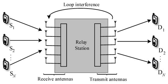
Figure 1.
Multipair full-duplex relaying system.
At time i, N source nodes , , simultaneously send their respective signals to the repeater station, and the repeater station sends signals to N destination nodes. To ensure the average transmit power of the source node and the relay node, assume and . The signal sent by the user is , then the received signal of the relay station and the destination node is
Among them and , respectively, the N source node to the relay station Repeaters transmitting terminal and the receiving end to the channel matrix N destination node, is the channel matrix between the receiving end and the transmitting end of the relay station, that is, the loop interference, , represents the loop interference intensity. It is assumed that the distance between the transmitting antenna and the receiving antenna is much greater than the distance between the components, so the channel between the transmitting antenna and the receiving antenna is independently distributed. and are Gaussian white noise at the relay end and the destination node, respectively, and each element is subject to independent and identically distributed .
2.1. Channel Estimation
In Rician channels, the relay cannot directly obtain CSI [20], so it is necessary to estimate and , and the estimated channel is the real channel. The channel between the base station and the user is
Here, is the small-scale fading between the user and the base station, where a deterministic LoS component and the random component of the corresponding scattered signal and ; is a large-scale fading diagonal matrix, and .
The Rician K-factor, defined as the power ratio between the LoS and NLoS components, is given by the following:
A larger K value indicates a stronger LoS component in the channel. Based on this, the fast fading channels are modeled as follows:
Among them, said random component, and the average random component of the elements is zero, real part and imaginary part are independent, each has a variance with distribution [21]; represents a deterministic component whose arbitrary rank is
where is the antenna spacing, is the wavelength, and is the n user arrival Angle. In order to obtain CSI, the uplink pilot sequence needs to be sent for channel estimation. The pilot matrix received by the transmitter and receiver of the relay is
Among them, and , respectively, the N source node to relay the sender and the N destination node to the relay channel matrix at the receiving end; is the energy of the pilot symbol [22]; and are Gaussian white noise subject to independent distribution; and are pilot sequences of and , assuming that all pilot sequences are paired orthogonally. Therefore, , , , and demand . In order to acquire the CSI, uplink pilot signals must be transmitted for channel estimation. In the uplink system model, users transmit pilot sequences of length , and the relay then estimates the corresponding channels based on the received pilots. The channel estimates can be obtained using the minimum mean square error (MMSE) estimation method.
Among them, , , , . The estimated matrix errors of and are represented by and , respectively, which can be written as
where , , , and are independent of each other, and , , and are subject to , , and . The nth diagonal element of and is , .
2.2. Data Processing
Perform linear reception processing on the signal received by the trunk [23], that is, multiply it by a linear reception matrix , and divide the received signal into N data streams, that is
Then the nth dataflow decodes and the nth element of is denoted by
Here, and are the nth columns of and , respectively, and represents the nth element of .
Due to the delay of relay processing, the relay sends signal as
Here, is the sexual preconditioning matrix and d is the delay processing. Therefore, the received signal at is
Here, and are the nth columns of and , respectively, and is the nth element of .
2.3. Linear Treatment Approach
2.3.1. MRC/MRT Processing
The MRC detection matrix and the MRT precoding matrix can be written as [24]
where is a normalized constant and satisfies the conditions of , so
2.3.2. EGC/EGT Processing
When the signal is processed by the equal-gain technique, the detection matrix and the pre-coded matrix can be written as
where is a normalized constant and satisfies the conditions of , so
3. Large Antenna Array Loop Interference Elimination
3.1. Using Large-Scale Antenna Arrays
When receiving antennas tend to infinity, the subvector Spaces of useful signal and loop interference are almost orthogonal, so the effect of loop interference can be eliminated by increasing the number of receiving antennas [25]. Assuming that for any , is fixed and , the received signal at the trunk can be written as
As can be seen from the above formula, when the receiving antenna tends to infinity, the loop interference disappears, and the interpair interference and noise also disappear. After the signal is processed by MRC/MRT and EGC/EGT, the original noise interference is eliminated and only the useful signal exists. At this time, the channel capacity between will increase to infinity, and the system performance is only affected by the quality of the channel between , independent of loop interference.
3.2. Adopt Large Transmitting Antenna and Low Transmitting Power
The transmitting power of the relay station determines the size of the loop interference [26]. Therefore, reducing the transmitting power can reduce the influence of the loop interference, but it will also affect the channel quality between , and the overall performance of the system will be worse. When the number of transmitting antennas is large, the relay station can concentrate the transmitted energy in the direction of the destination node and reduce the energy in other directions [27]. Therefore, when large-scale antennas are used in the repeater station, the relay transmission power can be reduced while keeping the communication link of unchanged.
Assuming that N and are fixed, the transmitting energy of the trunk is , and for any finite , when , the signal received by the trunk after MRC/MRT processing and EGC/EGT processing is
The signal received by the destination node after MRC/MRT processing and EGC/EGT processing is
As can be seen from the above formula, by scaling the transmitting antenna to , the loop interference at the trunk end disappears. Although the transmit power is reduced, the array gain increases with the increase in , so the useful signal strength received by the destination node is sufficient. At the same time, due to the orthogonality of the channel vector, the interference between user pairs disappears, and the channel quality from the relay to the destination node is good.
4. System Performance Analysis
4.1. Reachable Rate Analysis
In this section, an approximate expression for the uplink spectral efficiency of the massive MIMO-based full-duplex relay system is derived, which is the achievable uplink rate of and after MRC/MRT and EGC/EGT processing. Because the reachable rate is affected by the weakest link or bottleneck link, the final value is the minimum reachable rate from the source node to the trunk and from the trunk to the destination node. The reachable rate is calculated using an alternative method where the received signal is considered to be a known average gain multiplied by the useful signal, plus uncorrelated noise. This approach is often applied to massive MIMO systems, and its advantage is that it does not need to provide destination instantaneous CSI, in which case the reachable rate of is
Here, and are the achievable rates of the transmission links of and , respectively, (15) can be rewritten as
Here, is the effective noise, which can be written as
In this case, the useful signal and the effective noise in (29) are not correlated. Since the uncorrelated additive noise in the worst case has the characteristic of independent Gaussian white noise with the same variance, the reachable rate expression from the source node to the relay end can be written as
Among them, , and are multi-pair interference, loop interference and additive noise interference, respectively.
Similarly, the expression of the reachable rate from the trunk to the destination node is
In massive MIMO, the central limit theorem guarantees the reliability of approximating the effective noise as additive Gaussian noise, where the effective noise is the sum of several parts. Therefore, the reachable speed limits in Equations (31) and (35) are accurate; (35) assumes that the destination node applies the statistics of the channel gain (that is, ) to decode the transmitted signal, where it is not necessary to know the CSI. To prove that the derived reachability rate expression can accurately predict system performance, (35) can be compared with the traversal reachability rate received using Sprite, where the relays , , and , , are known. In this case, the reachable rate of is
Here, the expressions for and are given by
It can be seen from the subsequent simulation that the reachable rate expressions of Equations (28) and (36) are relatively consistent, especially when the transmitting antenna and receiving antenna are large.
4.2. MRC/MRT Approach
Theorem 1.
After MRC/MRT processing, the exact expression of the reachable rate of can be obtained by means of Equation (28)
Here, the expressions for and are given by
4.3. EGC/EGT Approach
Theorem 2.
After EGC/EGT processing, the exact expression of the reachable rate of can be obtained by the method of Equation (28)
Here, the expressions for and are given by
5. Performance Evaluation
5.1. Spectral Eefficiency
Next, the system performance is analyzed in terms of spectral efficiency, and let T denote the coherence time, during which the user sends the pilot sequence of length A for training and the rest time for data transmission; therefore, the uplink spectral efficiency is
Here, is the MRC/MRT treatment and the EGC/EGT treatment, respectively. According to Theorems 1 and 2 and Equation (47), the expression of full-duplex spectral efficiency after MRC/MRT and EGC/EGT processing is
5.2. Energy Efficiency
In this section, the advantages of having a large number of antennas in a relay station are studied.
Case 1: Assume , , and are fixed, where , . When , the approximate expression of spectral efficiency after MRC/MRT treatment and EGC/EGT treatment is
Among them,
When the above formula is reduced to and in proportion, the overall performance of the system will remain unchanged, assuming that for any n, there is , then Equations (50) and (51) can be written as
Among them, . As can be seen from the above formula, the use of large-scale antennas can reduce the user’s transmission power, and the total spectral efficiency is N times higher than before.
Case 2: Assuming and are fixed, with and , when and , , the approximate expression of spectral efficiency is
According to the above formula, when the uplink frequency transmission energy and transmission power are the same, the spectral efficiency can be reduced to and .
5.3. Compare Full-Duplex and Half-Duplex
In this section, system performance in full duplex and half duplex modes is compared. Compared to full duplex, half duplex mode does not cause loop interference, but it also results in a reduction in the transmission rate, and the transmission time is only half that of full duplex mode. Therefore, we assume that the user sends the same power in the coherence interval, that is, the coherence time used in half duplex mode is twice that in full duplex mode. At this time, the approximate expression of spectral efficiency after MRC/MRT processing and EGC/EGT processing is
In this paper, a hybrid relay mode is proposed. When , the spectral efficiency of full-duplex mode is higher than that of half-duplex mode, and is the balance of the spectral efficiency of the full-duplex and half-duplex modes.
5.4. Power Distribution
In the previous section, we assumed that the transmission power is the same for all users. However, different power distribution schemes can lead to varying system performance. Therefore, in this section, we assume that the transmission powers are different for different users, and the training time and pilot power are given. Based on Ngo’s design approach [28], we propose a power allocation algorithm to maximize the energy utilization of each node. Assuming that the transmitted power of the nth source is , the energy efficiency in full-duplex mode is
To translate this into mathematics, it can be written as
Here, is the given spectral efficiency, and and are the peaks of and .
From (48), (49) and (62), it can be seen that the energy optimization problem in (62) can be rewritten as
Among them, , .
When the system uses MRC/MRT processing, , , , , , , , , .
When the system uses EGC/EGT processing, , , , , , , , , .
Therefore, (64) is equivalent to
Since , , , and is all greater than or equal to 0, (64) is rewritten as
We find that the above objective functions and inequality constraints are positive functions, and can effectively find approximate solutions by solving GP sequences. More precisely, when and are used, can be used to approximate . Therefore, near point , the left side of the equation constraint can be approximated as
Therefore, the optimization problem of (66) can be transformed into a geometric programming problem, and the specific algorithm is as follows (Algorithm 1).
| Algorithm 1 Successive approximation algorithm |
| 1: Initialization: Set , select as the initial value of , assume error , maximum number of iterations L and parameter . 2: Iteration i: Calculate and , and then solve the geometric programming problem. Let us call the solution. 3: If or , the algorithm ends; otherwise, turn to step 4. 4: Set and , and return to step 2. |
6. Numerical Results
In this paper, the full-duplex relay scenario under massive MIMO is studied. The simulation environment used is as follows: Users are evenly distributed in hexagonal cells with a radius of 1000 m; the minimum distance between the user and the base station is 100 m; the number of users per cell ; the noise power is 1; pilot sequence length ; the symbol length of each frame ; number of antennas .
Figure 2 shows the results of the total spectral efficiency as a function of SNR for the MRC/MRT and EGC/EGT treatments for different antenna numbers. At this time, the signal-to-noise ratio ; loop interference . The spectral efficiency of different linear processing methods is given by Equations (39) and (44), and the Monte Carlo simulation is given by Equations (28), (31) and (35). It can be seen from the figure that the simulation value of the spectral efficiency is not much different from the theoretical value after linear processing. At 15 dB, the spectral efficiency difference between the two schemes is only 0.53 bits/s/Hz. Its overall trend is close to the simulation value. The system spectral efficiency increases with the increase in the signal-to-noise ratio and eventually tends to a constant value. When the signal-to-noise ratio is fixed, the larger the number of antennas, the greater the spectral efficiency. Moreover, the simulation curve of EGC/EGT is always slightly lower than that of MRC/MRT. Compared with the MRC/MRT method, the EGC/EGT method has the advantages of a simple hardware structure and low cost. Moreover, it only relies on the phase of the signal and does not require amplitude information. Although it is slightly inferior to the maximum ratio merging/transmission scheme in terms of SNR, its advantage in the trade-off between engineering implementation and complexity is obvious, and it is suitable for some occasions with high requirements for signal quality. Therefore, later on, it can be considered to use the simpler EGC/EGT scheme instead of the MRC/MRT scheme for linear processing of the signal.
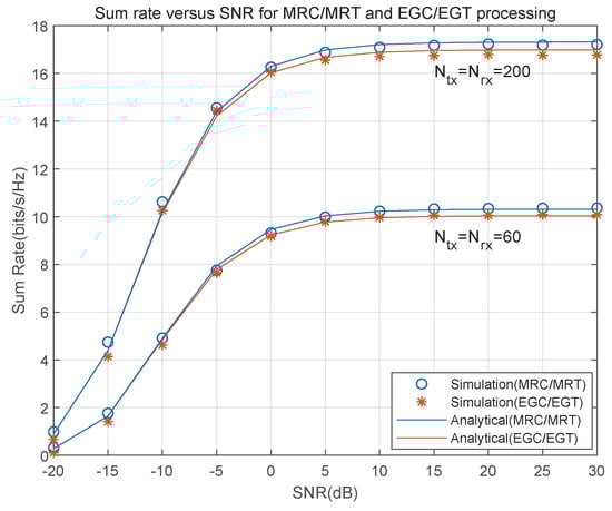
Figure 2.
The relationship between spectral efficiency and SNR under MRC/MRT and EGC/EGT approaches.
Figure 3 compares the calculation methods of two spectral efficiency simulations, namely the spectral efficiency simulation values of Equations (28) and (36). Among them, the method adopted by Formula (28) does not require the destination to know the instantaneous CSI, while Formula (36) uses the wizard reception to give a definite instantaneous CSI for later calculation. As can be seen from the figure, the performance gap between the two calculation methods is very small, and the curve trend increases with the increase in SNR, which proves that it is feasible to use channel statistics to detect sent signals. Therefore, the spectrum efficiency expression given by Equation (28) can accurately predict system performance.
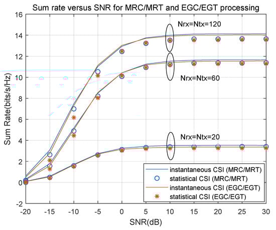
Figure 3.
Comparison of two spectral efficiency simulation methods.
Figure 4 shows the change trend of the user’s required transmission energy demand per 1 bit/s/Hz. At this time, assume that , , studied the relationship between the number of base station antennas and the energy required by the user to send signals in and , and verified that the use of a large-scale antenna array can improve the system performance. According to the loopback interference intensity and the user’s transmission, power is divided into four cases: (1) ; (2) ; (3) ; (4) . It can be seen from the figure that the energy required for users to send signals gradually decreases as the number of base station antennas increases. When the loopback interference is strong and the number of antennas is constant, the energy efficiency can be improved by increasing the number of base station antennas. In addition, the intensity of the loopback interference affects the spectral efficiency. The required transmission energy increases with the increase in the loopback interference intensity. However, for cases where the loopback interference intensity is large and the number of base station antennas is relatively small, even if the transmission energy is infinite, a higher spectral efficiency cannot be achieved. Therefore, large-scale antenna arrays need to be used to reduce the impact of the loopback interference and thereby improve the spectral efficiency. When the number of base station antennas is fixed, the transmission energy required by the MRC/MRT scheme is always slightly lower than that of the EGC/EGT scheme, but generally not much different. Considering the characteristics of low complexity and low latency of the EGC/EGT scheme, the simpler EGC/EGT scheme can be used to replace the MRC/MRT scheme in linear processing later.
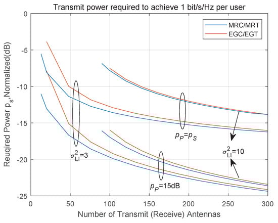
Figure 4.
The change trend of the user’s transmission energy demand per 1 bit/s/Hz.
Figure 5 shows the spectral efficiency performance of the system in full-duplex and half-duplex modes under different loop interference intensities. Assume that , and . As can be seen from the figure, in full-duplex mode, MRC/MRT processing is superior to EGC/EGT processing in terms of performance, and its spectral efficiency gradually decreases with the increase in loop interference. When the loop interference is very large, the spectral efficiency of the two linear processing modes is very close. In half duplex mode, the spectral efficiency is not affected by loop interference and, therefore, remains unchanged. Notably, when , the full-duplex mode can suppress the loop interference power by up to 18 dB, thereby maintaining its performance advantage. When the loop interference intensity is low, the spectral efficiency of full-duplex mode is much higher than that of half-duplex mode, because half-duplex mode needs to be multiplied by 1/2 preprocessing coefficient. When the intensity of loop interference is strong, the existence of loop interference affects the full-duplex processing, and the spectral efficiency of the half-duplex mode is higher than that of the full-duplex mode. Therefore, the above observations also prove that in order to improve the spectral efficiency, different processing modes should be selected in different cases.
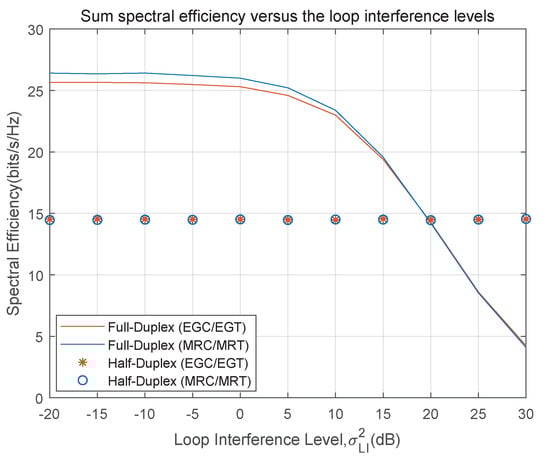
Figure 5.
The relationship between spectral efficiency and loop interference in two operating modes.
Figure 6 shows the trend of the spectral efficiency of half-duplex and full-duplex relays in relation to the number of base station antennas. It can be seen from the figure that when the MRC/MRT and EGC/EGT schemes are adopted, the system spectral efficiency obtained in the full-duplex mode is significantly higher than that in the half-duplex mode. This is because the half-duplex mode can only perform receiving or transmitting at the same time, and the improvement in spectral efficiency performance is relatively slow. Moreover, the EGC/EGT scheme is only slightly lower than the MRC/MRT scheme. It indicates that the adoption of the EGC/EGT scheme in linear processing is feasible. Furthermore, the spectral efficiency of both increases with the increase in the number of base station antennas. Thus, it can be seen that configuring a large number of antennas at the relay end can effectively reduce the impact of loopback interference and improve the system performance in full-duplex mode.
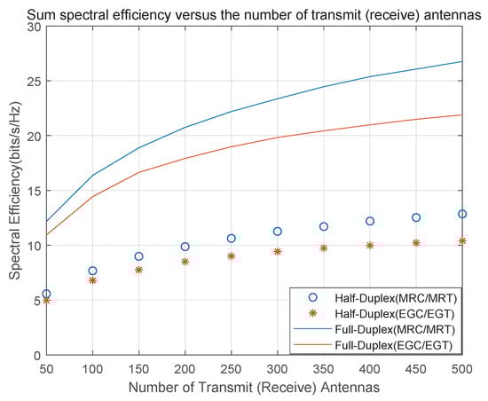
Figure 6.
The relationship between the spectral efficiency of half-duplex and full-duplex relays and the number of base station antennas.
Figure 7 shows the relationship between the total spectral efficiency of the system and the cumulative distribution function in the half-duplex, full-duplex and hybrid relay modes. Assume that , and . It can be seen from the figure that the performance of the MRC/MRT scheme is superior to that of the EGC/EGT scheme, but the overall trend is not much different. When considering the MRC/MRT scheme or the EGC/EGT scheme separately, under the same cumulative distribution function, the full-duplex mode can provide higher spectral efficiency for the system, and the performance fluctuation of the full-duplex mode is smaller in different situations, showing good stability. Furthermore, the hybrid relay mode established in this chapter can flexibly select the optimal scheme of spectral efficiency for full-duplex and half-duplex modes in different scenarios, thereby providing the best system spectral efficiency performance.
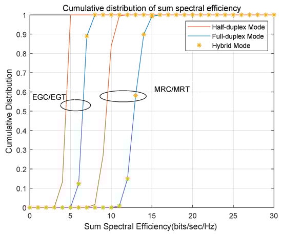
Figure 7.
Relationship between spectral efficiency and cumulative distribution function under three operating modes.
Figure 8 shows the relationship between the bit error rate (BER) of the system and the signal-to-noise ratio after MRC/MRT and EGC/EGT processing in full duplex mode. At this point, the number of characters sent per frame is , , , and , and the relay station adopts 2PSK mode to modulate and demodulate the signal. It can be seen from the figure that with the increase in the signal-to-noise ratio, the bit error rate performance of both the MRC/MRT scheme and the EGC/EGT scheme has improved, and the bit error rate performance of the MRC/MRT scheme is superior to that of the EGC/EGT scheme. The gap in bit error rate between the two gradually widens. Although the bit error rate performance of the EGC/EGT scheme is slightly lower than that of the MRC/MRT scheme, it still provides better spectral efficiency performance within a certain range. When , the bit error rates of the two linear processing methods differ by only about 0.02 dB, which proves that the adoption of the EGC/EGT scheme in large-scale MIMO is feasible.
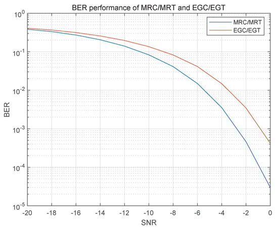
Figure 8.
The relationship between bit error rate and SNR under MRC/MRT and EGC/EGT approachs.
Figure 9 shows the relationship between the number of antennas of the base station and the bit error rate after MRC/MRT and EGC/EGT processing of the signal sent by the user. At this time, three situations are considered: (1) ; (2) ; (3) , in which and , respectively, send the energy source node and relay node, assume that , . As can be seen from the figure, the bit error rate performance of MRC/MRT and EGC/EGT processing decreases with the increase in the number of base station antennas, and eventually tends to a fixed value, and the bit error rate performance of case 2 is the worst among the three, because the loop interference at this time has a great impact on the signal receiving end. The bit error rate performance of case 1 and case 3 has little difference when the number of antennas is small. Then, with the increase in the number of antennas, the bit error rate performance of case 3 is gradually better than that of case 1. This is because the use of a large-scale antenna array reduces the influence of loop interference on receiving nodes, thus improving the spectral efficiency performance of the system. Finally, for MRC/MRT and EGC/EGT schemes, the bit error rate performance of MRC/MRT in case 2 is better than that of EGC/EGT schemes, but in case 1 and case 3, the bit error rate performance of the two schemes is basically the same. Therefore, EGC/EGT schemes can be considered to replace MRC/MRT schemes in future work.
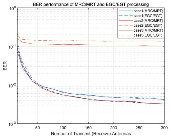
Figure 9.
The relationship between the number of base station antennas and the bit error rate in MRC/MRT and EGC/EGT schemes.
7. Conclusions
This paper investigates the performance of large-scale MIMO systems based on full-duplex relay communication in a Rician fading channel environment. The relay station employs the MMSE method to obtain an imperfect CSI channel estimation matrix. In terms of linear processing, the EGC/EGT scheme is applied for the first time and compared with the conventional MRC/MRT scheme. Both exact and approximate closed-form expressions for system spectral efficiency are derived. The simulation results demonstrate that employing a large antenna array can effectively eliminate the impact of loop interference, thereby suppressing inter-pair interference and noise. When the number of relay antennas approaches infinity, the transmission powers of the users and the relay can be reduced to and , respectively. Moreover, the spectral efficiency performance of the EGC/EGT scheme is only slightly inferior to that of the traditional MRC/MRT scheme, with a negligible difference overall. For instance, when , the bit error rates of the two linear processing methods differ by only about 0.02 dB. The spectral efficiencies of full-duplex and half-duplex systems are also compared, showing that the full-duplex mode can improve spectral efficiency by a factor of . Furthermore, a hybrid relay scheme is proposed, which allows for the optimal selection between full-duplex and half-duplex modes under given conditions, thereby significantly enhancing system spectral efficiency. Finally, a power allocation strategy is introduced to further optimize spectral efficiency. Under constraints on total spectral efficiency and peak power, the transmission powers of both users and the relay are optimally allocated, resulting in significant improvements in energy and spectral efficiency. Considering the low complexity, low latency, and simple hardware structure of the EGC/EGT scheme, it is of great practical significance to adopt this scheme as a substitute for the MRC/MRT scheme in large-scale MIMO systems based on full-duplex relay communication.
Author Contributions
Conceptualization, methodology, software, writing original draft preparation, M.W.; visualization, W.L.; resource, data curation, M.J.; writing—review and editing, B.Z. and M.W.; validation, B.Z. and S.-N.J.; supervision, funding acquisition, M.W. All authors have read and agreed to the published version of the manuscript.
Funding
This research was funded by Joint Funds of Liaoning Science and Technology Program under grant number 2023JH2/101800032.
Data Availability Statement
The data presented in this study are available upon request from the corresponding author.
Conflicts of Interest
Authors Wenqing Li and Meng Jin were employed by the Dalian Gona Technology Group Co. Ltd. The remaining authors declare that the research was conducted in the absence of any commercial or financial relationships that could be construed as a potential conflict of interest.
References
- van der Meulen, E.C. Three-terminal communication channels. Adv. Appl. Probab. 1971, 3, 120–154. [Google Scholar] [CrossRef]
- Marina, N.; Kavcic, A.; Gaarder, N.T. Capacity Theorems for Relay Channels with ISI. In Proceedings of the 2008 IEEE International Symposium on Information Theory, Toronto, ON, Canada, 6–11 July 2008; pp. 479–483. [Google Scholar] [CrossRef]
- Xiong, S.; Chen, Z.; Jiang, N.; Zhao, J.; Liu, L. Performance Optimization of Multipair Massive MIMO Polarized Relay Systems. Electronics 2023, 12, 3184. [Google Scholar] [CrossRef]
- de Pinho, P.H.U.; Couras, M.d.F.K.B.; Favier, G.; de Almeida, A.L.F.; da Costa, J.P.J. Semi-Blind Receivers for Two-Hop MIMO Relay Systems with a Combined TSTF-MSMKron Coding. Sensors 2023, 23, 5963. [Google Scholar] [CrossRef]
- Shao, Y.; Gulliver, T.A. Transceiver Optimization for Multiuser Multiple-Input Multiple-Output Full-Duplex Amplify-and-Forward Relay Downlink Communications. Telecom 2024, 5, 216–227. [Google Scholar] [CrossRef]
- Hwang, D.; Yang, J.; Nam, S.S.; Song, H.K. Full Duplex Relaying with Intelligent Reflecting Surface: Joint Beamforming and Phase Adjustment. Mathematics 2022, 10, 3075. [Google Scholar] [CrossRef]
- Yu, S.; Liu, X.; Cao, J.; Zhang, Y. Low-Resolution ADCs for Two-Hop Massive MIMO Relay System under Rician Channels. Entropy 2021, 23, 1074. [Google Scholar] [CrossRef]
- Chen, X.; Savaux, V.; Crussière, M.; Savelli, P.; Yao, K.C. Constrained-MMSE Combining for Spatial Domain Self-Interference Cancellation in Full-Duplex Massive MIMO Systems. IEEE Open J. Commun. Soc. 2024, 5, 649–663. [Google Scholar] [CrossRef]
- Kim, S.M.; Lim, Y.G.; Dai, L.; Chae, C.B. Performance Analysis of Self-Interference Cancellation in Full-Duplex Massive MIMO Systems: Subtraction Versus Spatial Suppression. IEEE Trans. Wirel. Commun. 2023, 22, 642–657. [Google Scholar] [CrossRef]
- Shen, H.; He, Z.; Xu, W.; Gong, S.; Zhao, C. Is Full-Duplex Relaying More Energy Efficient Than Half-Duplex Relaying? IEEE Wirel. Commun. Lett. 2019, 8, 841–844. [Google Scholar] [CrossRef]
- Mahmood, M.; Koc, A.; Morawski, R.; Le-Ngoc, T. Achieving Capacity Gains in Practical Full-Duplex Massive MIMO Systems: A Multi-Objective Optimization Approach Using Hybrid Beamforming. IEEE Open J. Commun. Soc. 2024, 5, 2268–2286. [Google Scholar] [CrossRef]
- Nordio, A.; Chiasserini, C.F. MIMO Full-Duplex Networks with Limited Knowledge of the Relay State. IEEE Trans. Wirel. Commun. 2021, 20, 2516–2529. [Google Scholar] [CrossRef]
- Guo, L.; Guan, M.; Sun, C.; Wang, Y. Achievable Rate Performance Analysis for Massive MIMO Relay Transmission. In Proceedings of the 2023 6th International Conference on Communication Engineering and Technology (ICCET), Xi’an, China, 24–26 February 2023; pp. 44–48. [Google Scholar] [CrossRef]
- Gupta, P.; Chakraborty, M.; Sharma, E.; Ghosh, D. Impact of Rician Phase Shifts on Multi-Pair Two-Way Full-Duplex Massive MIMO Relaying. In Proceedings of the 2024 IEEE Wireless Communications and Networking Conference (WCNC), Dubai, United Arab Emirates, 21–24 April 2024; pp. 1–6. [Google Scholar] [CrossRef]
- Shokoohifard, S.; Doost-Hoseini, A.M.; Tabataba, F.S. Resource Allocation in a MIMO Full-Duplex Relay Network With Imperfect CSI and Energy Harvesting. IEEE Syst. J. 2022, 16, 3950–3959. [Google Scholar] [CrossRef]
- Peng, Z.; Wang, S.; Pan, C.; Chen, X.; Cheng, J.; Hanzo, L. Multi-Pair Two-Way Massive MIMO DF Relaying Over Rician Fading Channels Under Imperfect CSI. IEEE Wirel. Commun. Lett. 2022, 11, 225–229. [Google Scholar] [CrossRef]
- Li, Z.; Han, S. Research on Physical Layer Security of MIMO Two-way Relay System. In Proceedings of the ICC 2022—IEEE International Conference on Communications, Seoul, Republic of Korea, 16–20 May 2022; pp. 3311–3316. [Google Scholar] [CrossRef]
- Ma, J.; Huang, C.; Li, Q. Energy Efficiency of Full- and Half-Duplex Decode-and-Forward Relay Channels. IEEE Internet Things J. 2022, 9, 9730–9748. [Google Scholar] [CrossRef]
- Lim, J.T.; Kim, T.; Bang, I. Impact of Outdated CSI on the Secure Communication in Untrusted In-Band Full-Duplex Relay Networks. IEEE Access 2022, 10, 19825–19835. [Google Scholar] [CrossRef]
- Hwang, D.; Yang, J.; Nam, S.S.; Joung, J.; Song, H.K. Cooperative Non-Orthogonal Multiple Access Transmission Through Full-Duplex and Half-Duplex Relays. IEEE Wirel. Commun. Lett. 2023, 12, 351–355. [Google Scholar] [CrossRef]
- Malayter, J.R.; Love, D.J. A Low-Latency Precoding Strategy for In-Band Full-Duplex MIMO Relay Systems. IEEE Trans. Wirel. Commun. 2024, 23, 1899–1912. [Google Scholar] [CrossRef]
- Hoang, T.M.; Tran, X.N.; Nguyen, B.C.; Dung, L.T. On the Performance of MIMO Full-Duplex Relaying System With SWIPT Under Outdated CSI. IEEE Trans. Veh. Technol. 2020, 69, 15580–15593. [Google Scholar] [CrossRef]
- Zhao, S.; Liu, J.; Shen, Y.; Jiang, X.; Shiratori, N. Secure Beamforming for Full-Duplex MIMO Two-Way Untrusted Relay Systems. IEEE Trans. Inf. Forensics Secur. 2020, 15, 3775–3790. [Google Scholar] [CrossRef]
- Antwi-Boasiako, B.D.; Ahiadormey, R.K.; Anokye, P.; Lee, K.J. On the Performance of Massive MIMO Full-Duplex Relaying With Low-Resolution ADCs. IEEE Commun. Lett. 2022, 26, 1259–1263. [Google Scholar] [CrossRef]
- Kandelusy, O.M.; Kirsch, N.J. Full-Duplex Buffer-Aided MIMO Relaying Networks: Joint Antenna Selection and Rate Allocation Based on Buffer Status. IEEE Netw. Lett. 2022, 4, 99–103. [Google Scholar] [CrossRef]
- Mobini, Z.; Mohammadi, M.; Tsiftsis, T.A.; Ding, Z.; Tellambura, C. New Antenna Selection Schemes for Full-Duplex Cooperative MIMO-NOMA Systems. IEEE Trans. Commun. 2022, 70, 4343–4358. [Google Scholar] [CrossRef]
- Nordio, A.; Chiasserini, C.F. Performance of mMIMO FD Relay Networks With Limited Relay State Knowledge. IEEE Wirel. Commun. Lett. 2022, 11, 1032–1036. [Google Scholar] [CrossRef]
- Ngo, H.Q.; Suraweera, H.A.; Matthaiou, M.; Larsson, E.G. Multipair Full-Duplex Relaying With Massive Arrays and Linear Processing. IEEE J. Sel. Areas Commun. 2014, 32, 1721–1737. [Google Scholar] [CrossRef]
Disclaimer/Publisher’s Note: The statements, opinions and data contained in all publications are solely those of the individual author(s) and contributor(s) and not of MDPI and/or the editor(s). MDPI and/or the editor(s) disclaim responsibility for any injury to people or property resulting from any ideas, methods, instructions or products referred to in the content. |
© 2025 by the authors. Licensee MDPI, Basel, Switzerland. This article is an open access article distributed under the terms and conditions of the Creative Commons Attribution (CC BY) license (https://creativecommons.org/licenses/by/4.0/).