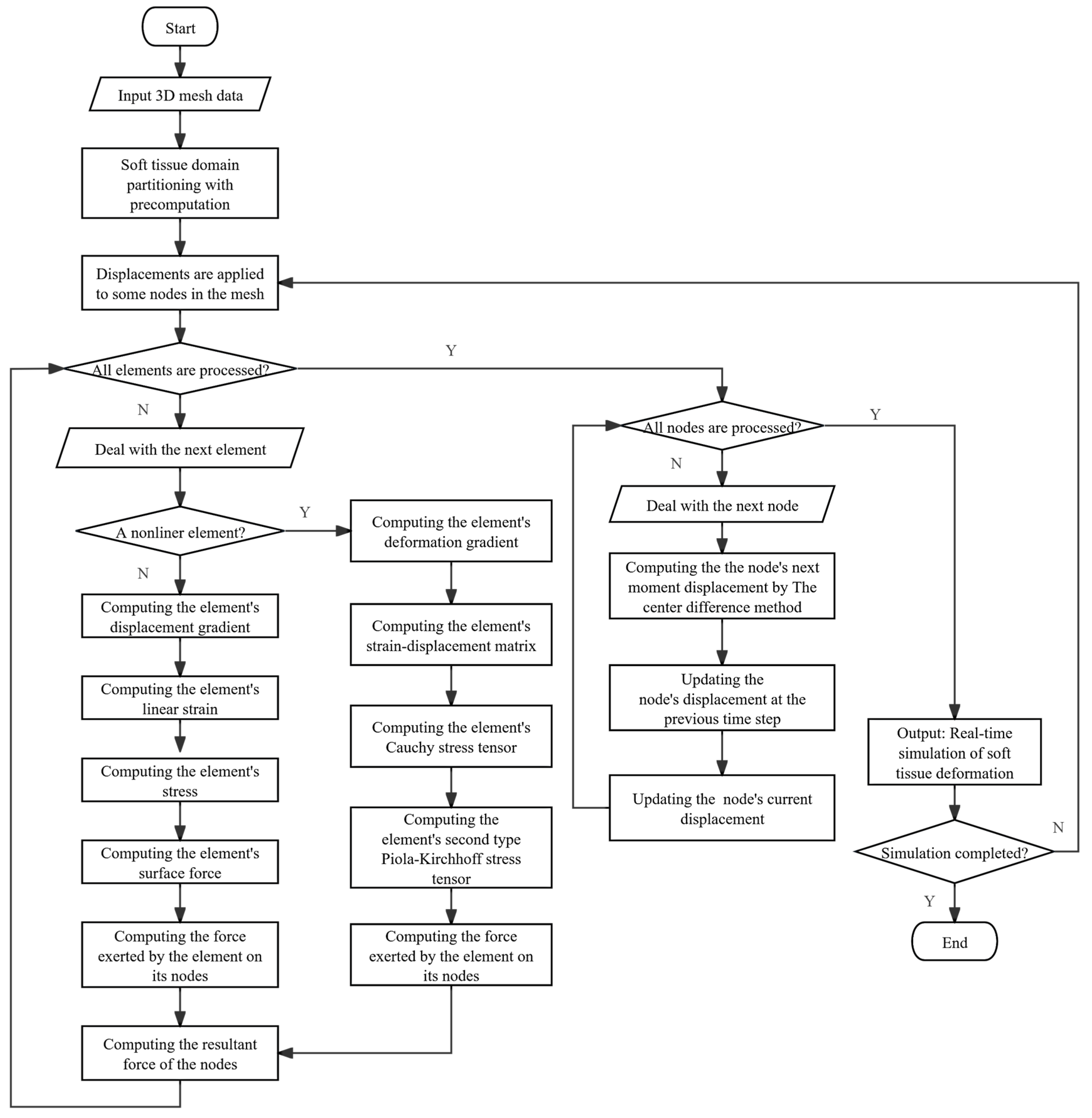
The DHD-FEA framework integrates four sequential stages: (1) soft tissue domain partitioning with precomputation, (2) subdomain-specific element stress analysis, (3) nodal resultant forces analysis, and (4) hybrid model-driven displacement resolution. Initially, the tissue geometry is partitioned into linear and nonlinear subdomains using biomechanical criteria, with tailored precomputation of domain-specific parameters (e.g., material properties and geometric invariants). A hybrid finite element methodology is selectively applied to each subdomain during the element analysis phase, deriving critical mechanical metrics—including stress tensors, strain distributions, and nodal interaction forces—through subdomain-appropriate constitutive models. Following this, nodal force integration synthesizes all element-induced force contributions at each node via vector summation, yielding the resultant force field across the tissue mesh. Finally, explicit time integration is implemented to compute dynamic nodal displacements between successive timesteps, enabling deterministic reconstruction of vertex trajectories and tissue morphodynamics. This framework achieves an optimized balance between computational tractability and biomechanical realism through adaptive domain-specific computation and hybrid numerical formulation.
The algorithm process is basically the same as that of the TLED algorithm. The difference lies in that during the element analysis, the DHD-FEA adopts two FEMs and will determine whether to use a linear model or a nonlinear model for the solution based on the type of element.
3.2.2. Subdomain-Specific Element Stress Analysis
The finite elements are divided into linear and nonlinear elements according to their location in the DHD-FEA method, as expressed in Equations (2) and (3).
O is the Operational Region, N is the Non-Operational Region, and I is the common area of the two regions. The equations of the two parts are similar, but the finite element equations are different. This section mainly describes the element stress analysis methods of linear finite elements and nonlinear finite elements.
The deformation of linear finite elements is constrained to less than 10% in this framework, enabling the use of the initial (reference) configuration to approximate the deformed geometry. The Cauchy strain tensor and Cauchy stress tensor are employed to characterize the material’s strain and stress states, respectively. Due to the fixed linear constitutive relationship between strain and stress—which remains invariant to the deformation magnitude—the linear model achieves higher computational efficiency compared to nonlinear approaches. However, this simplification compromises simulation accuracy as it neglects geometric and material nonlinearities inherent to large deformations.
A tetrahedral element with nodes
,
,
, and
has initial nodal positions
,
,
, and
and deformed positions
,
,
, and
, as illustrated in
Figure 6. The displacement field must be determined throughout the element to compute the Cauchy strain tensor, which requires derivation of the displacement gradient. For an arbitrary material point within the tetrahedron, let its initial coordinate be
and deformed position be
. The weights governing this point’s spatial relationship to the other tetrahedral nodes remain invariant throughout the deformation process. The
and
of a point are calculated using Equation (4), as follows:
are the weights of a point, and
is calculated with Equation (5) as follows:
In the same way,
is calculated as follows:
are the weights of a point, and
is calculated using Equation (7) as follows:
Finally, the position of a point after deformation is calculated as follows:
is a 3 by 3 matrix representing the mapping of any point position inside the tetrahedron before and after deformation, and the displacement of any point can be expressed as . And since remains constant throughout the simulation process, it is feasible to pre-calculate it.
Therefore, the displacement gradient of a point is calculated using the following equation:
where
I is the identity matrix, and the Cauchy strain tensor can be expressed as follows:
The Cauchy stress
is obtained through the constitutive equation after calculating the Cauchy strain tensor. The Cauchy stress σ is defined as shown in Equation (11):
where
df is the force acting on an infinitesimal surface in space,
dA is the area of that surface, and
n is the unit normal vector to the surface.
Therefore, the resultant force acting on each face of the tetrahedral element due to stress can be obtained from Equation (12):
where
a denotes the Cauchy stress tensor,
n is the unit normal vector to the triangular face of the tetrahedral element, and
A represents the area of the triangular face. Since the tetrahedron is modeled as a linear finite element, the resultant surface force
f can be uniformly distributed to each node of the triangular face, thereby allowing the nodal forces
exerted by the tetrahedral element on all nodes to be determined.
- 2.
The nonlinear finite elements stress analysis method
The nonlinear model of the DHD-FEA in the surgical area employs the TLED algorithm. Due to the substantial deformations often exhibited by soft tissues in surgical regions, linear strain tensors such as the infinitesimal (Cauchy) strain tensor are inadequate for solving such nonlinear problems. Instead, the Green–Lagrange strain tensor is adopted as the nonlinear strain measure and the stress tensor is correspondingly replaced by the Second Piola–Kirchhoff stress tensor. Furthermore, the constitutive relationship between stress and strain in these materials is not fixed. A simplified yet effective nonlinear framework for modeling such behavior is the hyperelastic model, where many biological soft tissues can be approximated as hyperelastic materials characterized by strain energy density functions. The nodal forces exerted by nonlinear elements on their corresponding nodes can be calculated using Equation (13).
is the vector form of the second Piola–Kirchhoff stress, is the strain–displacement matrix, and is the initial volume of an element. This equation performs force analysis at the element level, with all variable values obtainable from the local information of the element.
The neo-Hookean model is employed to solve for the stress tensor
. The stress components
are derived by differentiating the neo-Hookean strain energy function W with respect to the Green strain tensor [
23,
24]. And the equation is as follows:
where
is the right Cauchy–Green deformation tensor. And
is calculated as follows:
As the strain–displacement matrix
is related to the geometry of the element, it changes with the geometry of the element. Because a tetrahedron contains four nodes,
can be represented as a set of its submatrices:
is the
I-th node of the corresponding element of the
I-th submatrix of
. And
is calculated as follows:
is the deformation gradient of the element. And
is calculated using Equation (18).
To solve for
, it is necessary to compute the derivatives of the shape functions with respect to the spatial coordinates
,
, and
. And the spatial derivatives of shape functions are typically calculated using the isoparametric finite element formulation. The core principle of the isoparametric finite element formulation lies in relating the displacement at any point within an element to the nodal displacements through shape functions. The shape function
at the four nodes
,
,
, and
can be expressed as
in a tetrahedral isoparametric element, where the isoparametric coordinates
r, s, and
t are defined in the range of [−1, 1], as shown in Equation (19):
where
i denotes the local index of the corresponding vertex within the element.
The relationship between the derivatives of the shape functions according to the rules of partial differentiation and the isoparametric coordinates is given in Equation (20).
Equation (20) derives the relationship between the partial derivatives of the shape functions with respect to the isoparametric coordinates and the partial derivatives of the shape functions with respect to the physical coordinates, as well as the partial derivatives of the physical coordinates with respect to the isoparametric coordinates, using the chain rule. Through a series of identity transformations, Equation (21) is obtained.
Therefore, the spatial derivatives of the shape functions (with respect to physical coordinates) can be computed, as shown in Equation (22):
, , and represent the derivatives of the shape functions with respect to the isoparametric coordinates in an isoparametric element. Since the isoparametric coordinates of points within each element remain invariant, the derivative values of the shape functions at the integration points are constant throughout the simulation.
For each tetrahedral element, the initial positions of its four nodes are , , , and . Since these positions remain invariant throughout the deformation simulation, the spatial derivatives of the shape functions computed via Equation (22) are also constant during the entire deformation process. Thus, the matrix can be computed using Equation (18), and subsequently, the strain–displacement matrix for the element can be obtained via Equation (16). With these matrices, the nonlinear internal forces acting on the element’s nodes can be further determined. Crucially, the matrix remains invariant throughout the entire deformation simulation, yet its computation is computationally intensive. Therefore, the matrix for each element is precomputed during the preprocessing stage, and the pre-computed data are directly reused in real-time simulations to significantly accelerate the deformation computation.
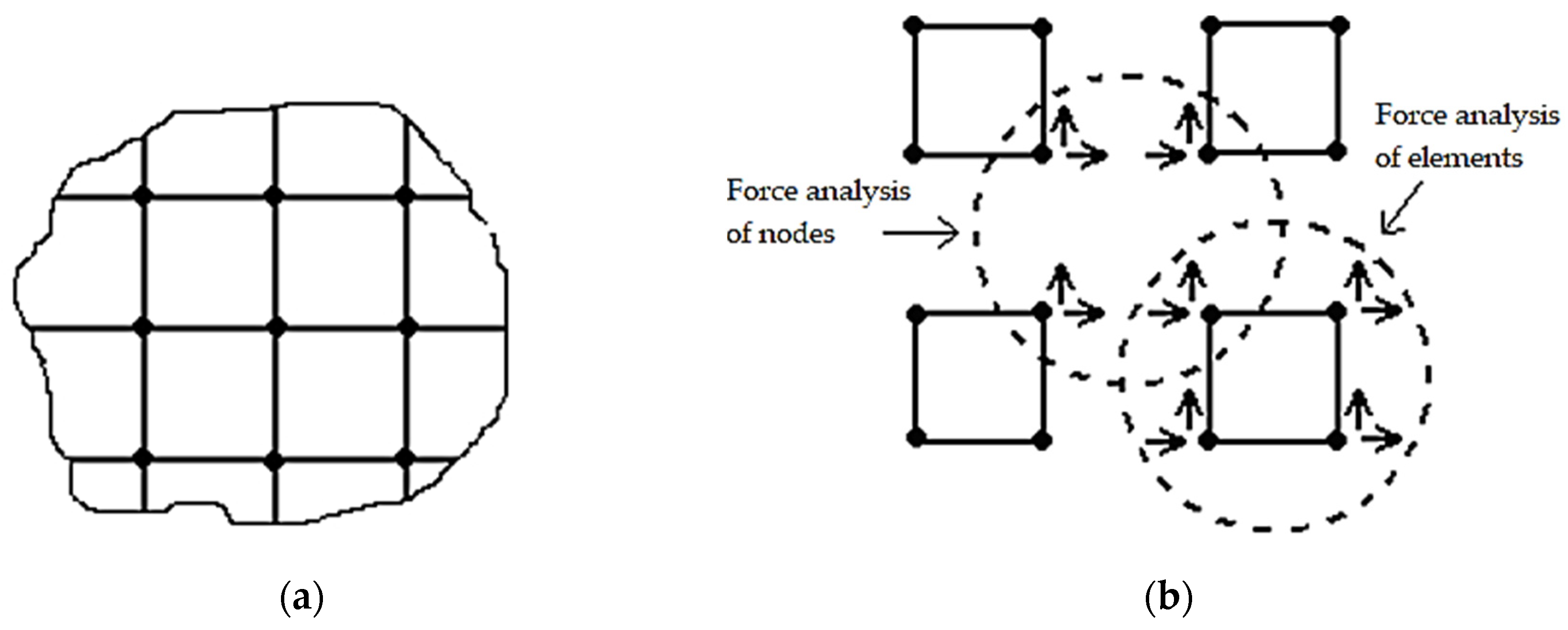
Following the mechanical analysis of linear and nonlinear zonal elements, it is necessary to apply all resultant forces to the interface nodes. The interfacial nodes connecting both zones, referred to as intermediate nodes, exhibit hybrid connectivity with both nonlinear and linear elements. Conventional Equations (2) and (3) typically require independent computation of these intermediate nodes followed by simultaneous solution of the coupled equation systems. However, the proposed algorithm eliminates the need for global stiffness matrix assembly, thereby enabling direct integration of intermediate nodes through a streamlined computational process. The forces exerted by each element on its connected nodes are computed without nodal type restrictions during element-level analysis to ensure comprehensive force transmission to all nodes—whether in nonlinear zones, linear zones, or intermediate positions. Subsequent nodal force analysis inherently incorporates all nodal points by calculating the resultant forces acting on each node through superposition of contributions from adjacent elements. This methodology naturally accommodates intermediate nodes within the standard computational framework, achieving systematic force equilibrium without necessitating special treatment for interfacial nodes.
3.2.3. Nodal Resultant Forces Analysis
The DHD-FEA determined the nodal force vectors
exerted by tetrahedral elements on their corresponding nodes following the elemental stress analysis. The subsequent computational phase necessitates the evaluation of the resultant force at each node
through systematic superposition of contributions from all topologically connected elements. Let
denote the force exerted by an incident element
e connected to the node for each nodal point within the discretized mesh. The resultant force
acting on the node due to all incident elements is computed through vector superposition as prescribed in Equation (23):
The total resultant force is computed as when external forces (e.g., applied nodal loads, boundary tractions, or body forces) act on node v.
The displacement field within an element is approximated through nodal displacement interpolation in the DHD-FEA, while distributed external forces and internal interactions between adjacent elements are consistently acting as nodal forces. This framework enables the application of Newtonian mechanics for nodal equilibrium analysis. For static systems, nodes remain in a stationary state governed by the equilibrium relationship expressed in Equation (24).
For dynamic systems without damping effects, the nodal dynamic equilibrium equation is formulated as
where
is the mass of a node, and
is the displacement of the node. The nodal acceleration
is the second derivative of the nodal displacement
with respect to time.
is the force exerted by the unit pair on the node, and
is the resultant force of the external forces acting on the node. For the nodes with damping effect, their dynamic equilibrium equations are as shown in Equation (26).
The damping term is added in the above equation, Equation (26). And represents the damping factor of the node, and the node velocity is the first derivative of the node displacement with respect to time.
3.2.4. Hybrid Model-Driven Displacement Resolution
All physical quantities remain independent of time in static systems. Static equilibrium equations can also be applied to quasi-static scenarios. The system states evolve temporally, but at a sufficiently slow rate that inertial and damping effects become negligible in such scenarios. These formulations are applicable to analyses including foundation settlement and dam impoundment. However, their suitability diminishes in surgical contexts involving tissue deformation and incision operations, where rapid state variations occur—for instance, the viscoelastic rebound and oscillation of organs following instrument indentation. When temporal displacement variations exhibit significant rates, necessitating the consideration of inertial effects, dynamic system formulations become imperative. In such systems, acceleration terms manifest explicitly in the governing equations, accompanied by velocity-dependent damping effects. Compared to static systems, displacement variables attain heightened significance in dynamic analyses. The fundamental governing equations of dynamics derive from force equilibrium principles rooted in Newtonian mechanics, incorporating both inertial and dissipative forces.
An exact solution can typically be obtained in static analysis. However, achieving an exact solution is significantly more challenging due to the need to account for material distribution and damping effects in dynamic analysis [
25]. It is necessary to generate at least a mass matrix to complement the stiffness matrix in dynamic finite element analysis. The assembly procedures for the mass matrix M and stiffness matrix K can be executed concurrently within finite element frameworks. Element-level mass matrices are initially formulated in local coordinate systems before undergoing coordinate transformation to the global system that mirrors the assembly methodology employed for the global stiffness matrix. A fundamental distinction between these matrices lies in the diagonalization capability of the mass matrix via direct lumping techniques. This diagonalization confers critical computational advantages: (1) the inversion of diagonal matrices requires substantially fewer operations compared to full matrices, and (2) the diagonal structure enables explicit time integration schemes at the element level without coupled equation solutions. Consequently, mass lumping significantly optimizes computational efficiency in dynamic simulations.
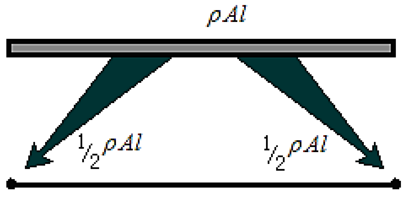
The objective of direct mass lumping (DML) is to generate a diagonally lumped mass matrix (DLMM) for dynamic systems. This technique allocates the total mass of element e to its nodal degrees of freedom by directly distributing mass contributions to individual nodes, thereby eliminating off-diagonal coupling terms associated with inter-nodal interactions. The simplest illustration of direct mass lumping involves a two-node prismatic bar element with length
l, uniform cross-sectional area
A, and mass density
, as depicted in
Figure 7.
The total mass
of a tetrahedral element (where
is material density and
V denotes element volume) is distributed to its four nodes using the mass lumping method as illustrated in
Figure 8.
The finite element mass matrix is transformed into a diagonal matrix via the direct mass lumping procedure, where elemental mass is redistributed to nodal degrees of freedom while preserving total mass conservation. Under the proportional damping assumption (
, where
is a material-dependent constant), the damping matrix inherits the diagonal structure from the lumped mass matrix. This formulation allows the stiffness term
to be expressed in the decoupled form of Equation (27):
e is the elements in the set, and is the force of an element on the node. Equation (27) describes that the internal forces acting on each node in a structural system can be calculated through the assembly of the global stiffness matrix followed by its multiplication with the nodal displacement vector. Alternatively, the second methodology involves conducting stress analysis at the element level, where individual unit contributions are resolved through constitutive relationships.
The diagonal configuration of both mass matrix
M and damping matrix
D indicates that nonzero elements exclusively populate their main diagonals, while off-diagonal entries remain 0. This structural property ensures that the mass and damping characteristics of each node operate independently, with no cross-coupling effects between distinct nodes in the system. The dynamic equilibrium in Equation (28), governing node
I, incorporates the combined effects of internal stress-induced resultant force
, its mass
, damping coefficient
, instantaneous displacement
, and externally applied load
.
The integration of governing equations with the inherent diagonal properties of mass and damping matrices establishes a hierarchical computational framework for deformation simulation. This methodology enables multi-level analysis by leveraging element-specific stress–strain relationships and nodal dynamic equilibrium principles, ensuring that localized force interactions are systematically resolved while maintaining global system compatibility.
The DHD-FEA methodology addresses the challenge of real-time tissue/organ deformation simulation in surgical contexts by strategically partitioning computational domains: nonlinear FEM formulations govern the surgical region to capture complex biomechanical responses, while linear FEM approximations are applied to non-surgical zones to reduce computational overhead. This multi-resolution framework optimizes computational resource allocation while maintaining physiological fidelity. Additionally, domain-specific numerical integration strategies are implemented to efficiently solve equilibrium equations, enabling stable convergence under large deformation scenarios. The temporal discretization of governing equations can be implemented through explicit or implicit integration schemes, each offering distinct computational trade-offs [
22]. But implicit integration methods maintain unconditional stability but require iterative solutions to couple nonlinear algebraic systems, resulting in significant computational demands. In contrast, explicit schemes achieve computational efficiency through non-iterative formulations, directly advancing solutions without solving coupled equations, a feature particularly advantageous for dynamic systems governed by strict time-step constraints.
The central difference method is an explicit integration scheme designed to approximate solutions for second-order differential equations [
21]. This approach is employed to solve Equation (28) in the DHD-FEA, leveraging its capability to compute state variables at subsequent time steps based entirely on current dynamic conditions. The temporal progression follows discrete time intervals governed by a fixed time step in computational dynamics simulations. When initializing a simulation at
with a defined temporal resolution
, the current state at time
t inherently determines the subsequent time increment as
through explicit temporal discretization. Within the framework of Equation (28), the displacement vector
constitutes the primary unknown requiring numerical resolution. Concurrently, all other system parameters including but not limited to velocity vectors, acceleration profiles, and environmental constraints become computationally accessible through explicit state transitions during each stepwise calculation. This deterministic progression ensures temporal causality while maintaining numerical stability through fixed-interval updates.
The central difference method employs iterative temporal discretization to determine the unknown displacement function
at subsequent time instant
, where temporal superscripts systematically denote measurement instances as illustrated in
Figure 9. This explicit algorithm calculates first-order derivatives at time
through symmetric differencing principles, utilizing displacement states from adjacent time intervals to construct velocity approximations.
Therefore, the first- and second-order temporal derivatives of displacement function
at time
t are formulated as follows:
is the second derivative at time
t. The nodal equilibrium equations are derived by substituting Equations (29) and (30) into Equation (28), resulting in the governing formulation expressed as Equation (31).
The governing equations are algebraically transformed through identity operations, ultimately yielding the consolidated formulation expressed as Equation (32).
And Equation (33) is obtained by simplifying Equation (32).
Equation (33) provides an efficient computational framework for determining nodal displacements at subsequent time steps in the DHD-FEA. This enables accurate reconstruction of object deformation characteristics through systematic time-domain integration.


