1. Introduction
With the increasing severity of global warming and greenhouse gas emissions, achieving carbon neutrality by 2050 has become a worldwide priority [
1,
2]. Global greenhouse gas emissions, encompassing carbon dioxide (CO
2), sulfur dioxide (SO
2), nitrogen oxides (NO
x), carbon monoxide (CO), and particulate matter (PM), are rising due to the excessive use of fossil fuel-derived energy sources [
3]. According to statistics, the transportation sector is the second largest emitter of greenhouse gases with total emissions reaching 7.65 Gt CO
2, accounting for 37% of global emissions [
4]. Therefore, the transportation industry is showing a strong trend of switching to electric vehicles (EVs) to replace traditional fossil fuel vehicles. With the outstanding advantages of zero emissions and high efficiency, EVs become the cleanest choice compared to conventional internal combustion engine (ICE) vehicles [
5,
6]. Recent data indicate that EVs have attained 100,000 units in 9 countries, with over 20 countries surpassing a 1% market share. The rising adoption of EVs has imposed more rigorous demands on their dependability and efficiency [
7].
The electric motor is a crucial integrated driving element that guarantees the traction of EVs. Enhancing the torque and efficiency of the electric motor can augment the performance and reliability of EVs [
8]. To improve the driving performance and efficiency of EVs, motor miniaturization has been pursued to reduce vehicle weight and enhance power density [
9]. However, the increase in power density also leads to significant heat generation, which poses critical challenges for motor reliability. Excessive heat accumulation can damage insulation materials, cause demagnetization of permanent magnets, and ultimately reduce the efficiency and lifespan of the motor [
10]. Therefore, effective motor thermal management is essential to ensure stable operation and prevent performance degradation due to overheating.
Air cooling is insufficient for high-speed EVs with extended driving requirements due to its low convective heat transfer coefficient and limited heat dissipation capability [
11,
12]. Phase-change material (PCM) cooling is impractical due to low thermal conductivity, limited heat transfer efficiency, and difficult in fixed position with a liquid phase [
13,
14]. Heat pipe cooling must be integrated with air cooling or liquid cooling, making the system complex and less viable for electric vehicle applications. Additionally, embedding heat pipes in stator slots reduces the copper fill factor and introduces a potential risk of leakage [
15,
16]. Refrigerant cooling requires additional refrigeration components, making the system bulky, complex, and expensive, limiting its feasibility for electric motor cooling in EVs [
17]. As the power density of electric motors continues to increase, conventional water jacket cooling (indirect liquid cooling) has become less effective in maintaining the desired thermal management. The primary limitation of this method lies in the indirect cooling channels, which introduce higher thermal resistance and reduce the efficiency of heat dissipation from the windings, the primary heat-generating component of the motor [
18]. Consequently, there is a growing demand for advanced thermal management technologies that offer minimal thermal resistance and enhanced cooling performance for next-generation electric motors.
To overcome the existing challenges, direct cooling has gained increasing attention as a potential solution for electric motor thermal management. Among various direct cooling techniques, spray cooling has emerged as a highly efficient approach, particularly for motors with high power densities. This method offers zero thermal resistance between the coolant and motor components, ensuring efficient heat dissipation and significantly enhancing cooling performance. As a result, spray cooling has become a preferred strategy for managing the thermal challenges associated with next-generation high-performance electric motors [
19].
Recent research efforts have evaluated the effectiveness of spray-based direct cooling systems in electric motors, focusing on parameters, such as coolant flow rate, nozzle configuration, and position. Garud et al. compared the effectiveness of water cooling and oil spray cooling systems in a 125 kW motor, with rotational speeds ranging from 2000 to 10,000 RPM and an oil flow rate and temperature of 6 LPM and 40 °C, respectively. The results demonstrated that oil spray cooling exhibited superior cooling performance, with a motor operating temperature of 156.32 °C, significantly lower than with water cooling [
20]. Davin et al. investigated the influence of nozzle geometry, coolant oil flow rate, inlet oil temperature, and motor rotational speed on cooling performance. The findings indicated that the coolant oil flow rate was the most significant factor in ensuring cooling efficiency [
21]. Ha et al. identified the optimal conditions for oil film formation by the oil spray method in a motor with hairpin windings. The results showed that the configuration of six nozzles with a diameter of 6.35 mm provided the most uniform oil distribution. Simultaneously, the most effective oil film formation was achieved at an oil flow rate of 6 LPM and an oil temperature of 40 °C [
22]. Kang et al. evaluated the effects of nozzle diameter and oil flow rate on heat transfer characteristics of oil spray cooling under overload conditions of a 15 kW motor. The study revealed that a 4 mm nozzle diameter provided the lowest motor temperature of 46.3 °C and the highest heat transfer coefficient of 7528.61 W/m
2·K. Furthermore, the cooling performance significantly improved with increasing oil flow rate [
23]. In addition, Rocca et al. suggested a hybrid cooling that combined jacket cooling and spray cooling. The findings indicated that the spray angle, nozzle position and number of nozzles significantly impact the spray cooling performance of the electric motor [
24]. Fang et al. explored the thermal performance characteristics of an oil–water hybrid cooling system in a 30 kW permanent magnet synchronous motor. The findings demonstrated that the hybrid system improved cooling efficiency by 15–19% compared to a conventional water cooling system [
25].
Recently, electric vehicles have been equipped with electric motors with increasing power density to match the performance of IC engine vehicles. Electric motors with increasing energy density demand an improved heat dissipation rate to achieve effective thermal management and, hence, the desired performance for the propulsion system. The widely used conventional cooling method is water jacket (indirect) cooling for electric motors, which has the limitation of increased thermal resistance and, thus, a lower heat dissipation rate between the motor components and coolant. Therefore, direct cooling is widely researched as an emerging cooling strategy to eliminate the limitations of indirect cooling. However, direct cooling through an approach with a spray nozzle or dripping holes involves major internal cooling of motor components and, thus, there are concerns about uneven heat distribution on housing and stator external parts. Therefore, to ensure the balance between the merits/demerits of direct cooling and indirect cooling, a hybrid concept of both cooling methods has been proposed in the present work, specifically targeting high power density electric motors. This study proposes a comprehensive approach to thermal management in electric motors based on direct spray cooling for the winding, stator, and indirect cooling channels for the motor housing. The open literature lacks a comprehensive parametric study to evaluate the heat transfer characteristics of hybrid direct–indirect oil cooling for electric motors. Unlike existing studies, which primarily focus on individual cooling methods, this work offers a unique parametric study of the hybrid direct–indirect oil cooling system, investigating the impact of key design parameters, such as spray hole diameter, coolant oil flow rate, and motor heat loss on the temperature distribution, heat transfer coefficient, friction factor, pressure drop, and performance evaluation criteria (PEC). By creating a robust database and analyzing the combined effects of these factors, this study provides new insights into optimizing hybrid direct–indirect oil cooling strategies and contributing to the advancement of thermal management technologies for next-generation high-power electric motors.
3. Results and Discussion
This section presents an elaboration on the heat transfer characteristics of electric motors with hybrid direct–indirect oil cooling under a variety of different influential parameters. The effect of spray hole diameter, volume flow rate of coolant oil, and heat loss level on the heat transfer characteristics are elaborated in
Section 3.1,
Section 3.2 and
Section 3.3, respectively. The discussed heat transfer characteristics include winding, stator, and housing temperature, heat transfer coefficient, friction factor, pressure drop, and PEC.
3.1. Effect of Different Spray Hole Diameters
To evaluate the impact of spray hole diameter on the heat transfer characteristics of the hybrid direct–indirect oil cooling system, numerical analysis was conducted at different spray hole diameters of 1.1 mm, 1.3 mm, 1.5 mm, and 1.7 mm with the motor heat loss at 2.6 kW. ATF SP-4 oil was utilized as the coolant oil to ensure effective heat dissipation throughout the motor components. The total coolant oil flow rate was maintained at 15 LPM, with a distribution of 11.25 LPM allocated to the direct cooling system and 3.75 LPM to the indirect cooling system. To establish consistent boundary conditions, the inlet temperature of the coolant oil and the initial temperature of the motor were set at 25 °C. The analysis examined the variations in the maximum temperature of the winding, stator, and housing, heat transfer coefficient (HTC), friction factor, pressure drop, and performance evaluation criteria (PEC). By analyzing the influence of spray hole diameter, this study aims to identify the optimal configuration that maximizes heat dissipation efficiency, enhances the HTC, and maintains an appropriate pressure drop for ensuring an effective balance between thermal performance and hydraulic efficiency.
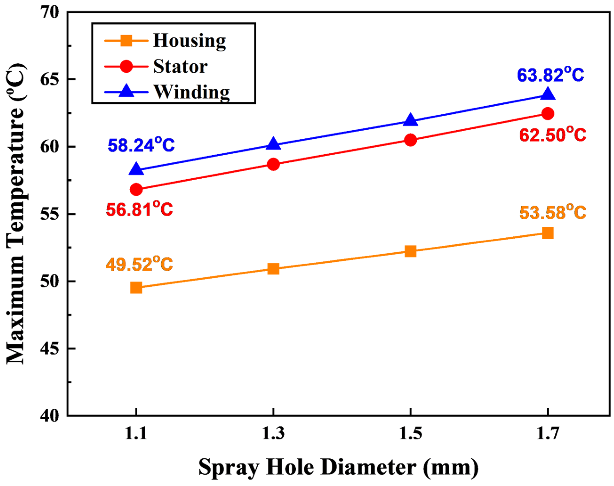
3.1.1. Winding, Stator, and Housing Temperature
The effect of spray hole diameter on the maximum temperature of the winding, stator, and housing is presented in
Figure 6. The findings indicate that an increase in spray hole diameter from 1.1 mm to 1.7 mm in the direct cooling system led to a corresponding rise in winding and stator temperature. Specifically, the maximum temperature of the winding and stator increased from 58.24 °C to 63.82 °C and from 56.81 °C to 62.50 °C, representing a 9.58% and 10.01% increase as the spray hole diameter expanded from 1.1 mm to 1.7 mm, respectively. This temperature increase can be attributed to the reduction in coolant oil pressure and velocity as the spray hole diameter increased. With larger hole diameters, the coolant oil exits the spray hole at a lower velocity, resulting in reduced contact force and surface interaction with the winding and stator. Consequently, the heat transfer efficiency decreases, leading to an increase in the winding and stator temperature.
Similarly, as the spray hole diameter increased from 1.1 mm to 1.7 mm, the maximum housing temperature rose from 49.52 °C to 53.58 °C, an increase of 8.19%. Although the indirect cooling system continuously dissipates the heat from the motor housing, the reduced cooling efficiency of the direct cooling system at larger spray hole diameters led to a higher winding and stator temperature, which, in turn, contributed to the increment in the housing temperature.
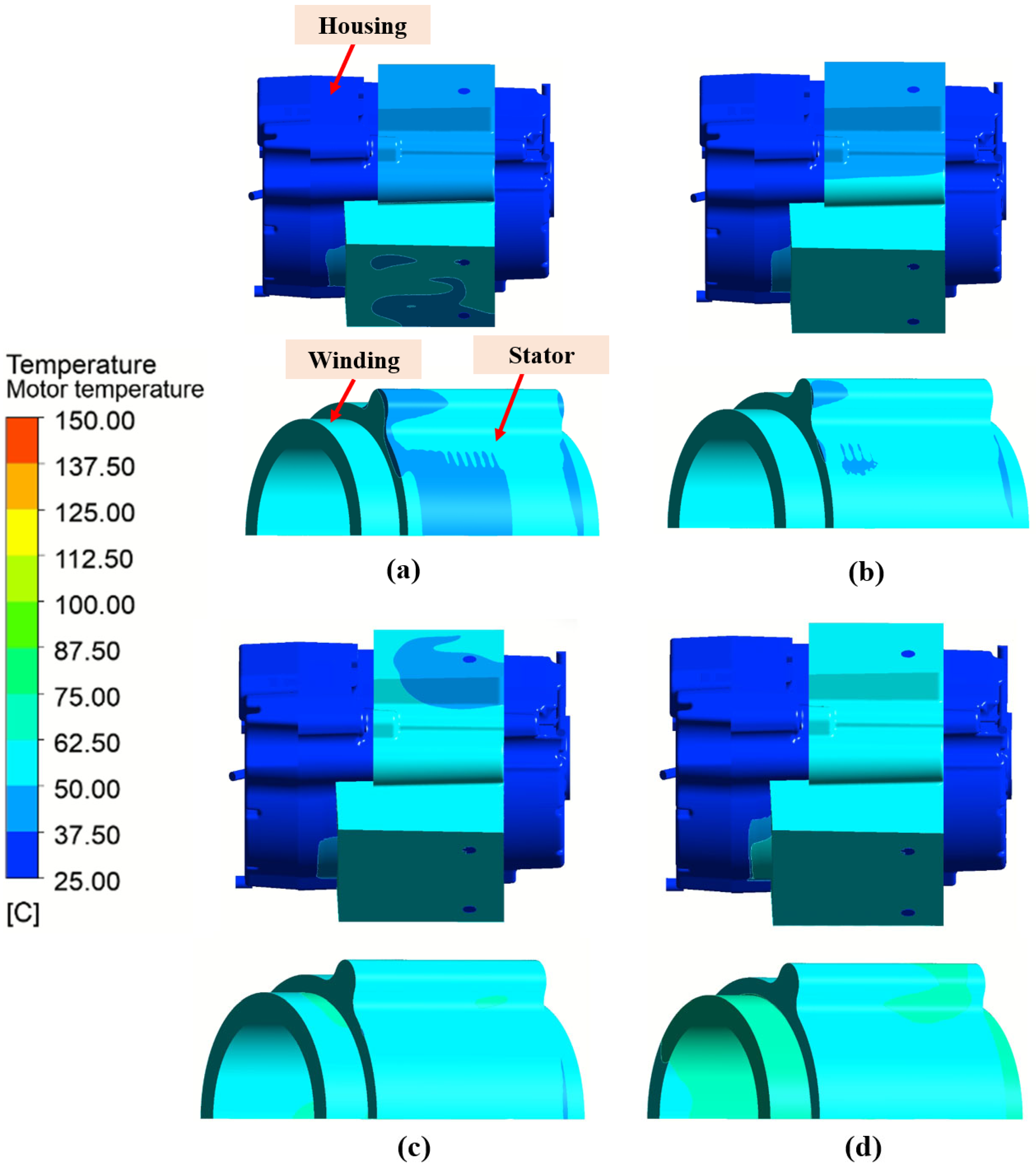
Figure 7 illustrates the distribution of the winding, stator, and housing temperatures for varying spray hole diameters, namely 1.1 mm, 1.3 mm, 1.5 mm, and 1.7 mm. The figure present the thermal profiles under each diameter configuration and highlight how the changes in spray hole size impact temperature distribution across the motor components. As the spray hole diameter increases, there is a corresponding rise in the temperatures of the winding, stator, and housing. Specifically, the larger spray hole diameters result in a decrease in the velocity of the coolant oil, which reduces its interaction with the motor components and subsequently lowers the cooling effectiveness. This effect is particularly evident in the winding and stator, where the maximum temperatures increase as the spray hole diameter expands. The temperature distributions depicted in the figure provide valuable insight into the trade-offs between hydraulic efficiency and cooling performance, offering a basis for optimizing the spray hole diameter to balance thermal management and energy consumption in the cooling system.
3.1.2. Heat Transfer Coefficient, Friction Factor and Pressure Drop
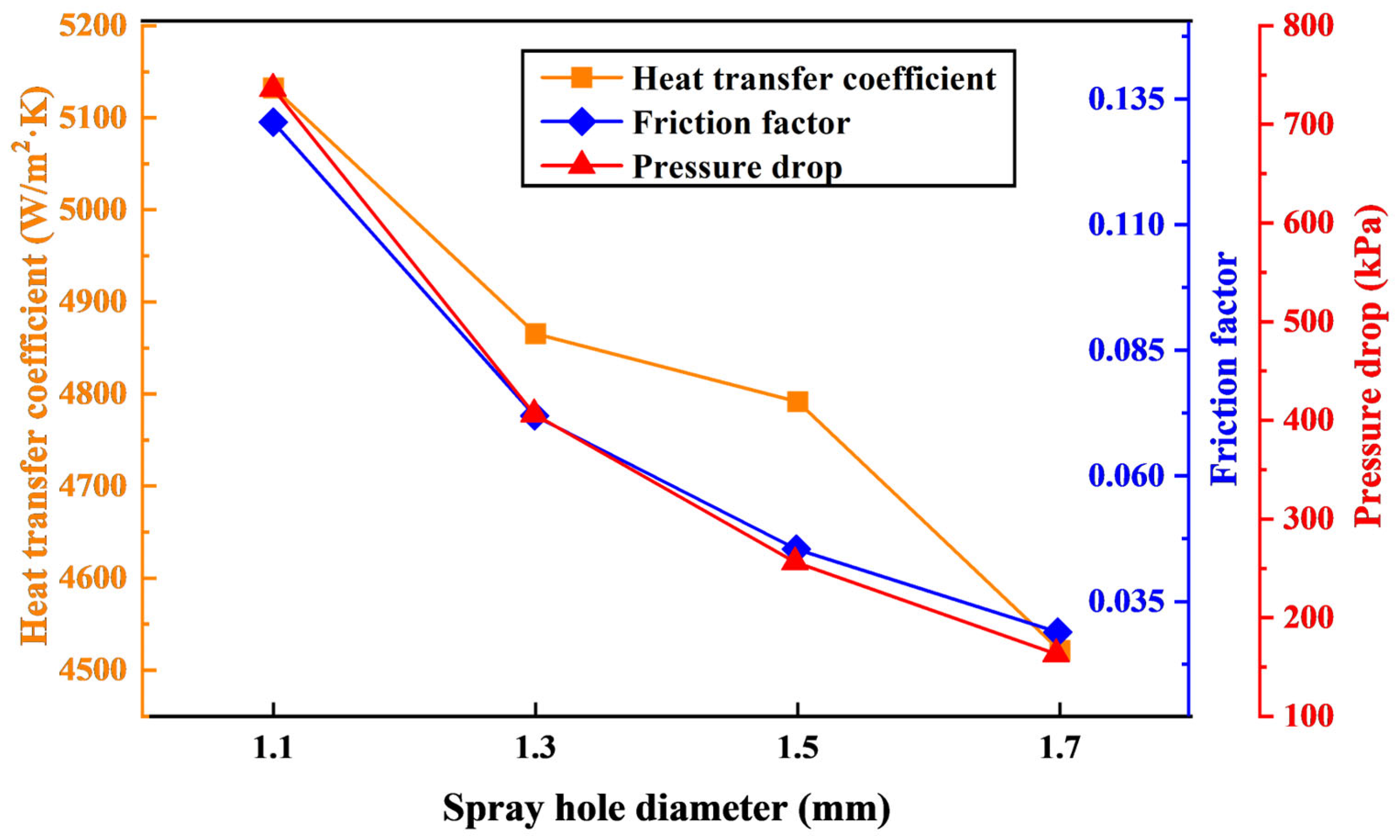
The relationship between the heat transfer coefficient (HTC), friction factor, and pressure drop for different spray hole diameters is presented in
Figure 8. The findings indicate a clear inverse relationship between spray hole diameter and HTC, where the HTC decreases as the spray hole diameter increases. Specifically, the HTC declined from 5132 W/m
2·K to 4521 W/m
2·K when the spray hole diameter increased from 1.1 mm to 1.7 mm. This trend can be attributed to the reduction in spray velocity and turbulence intensity as the hole diameter increases. A larger hole diameter results in lower coolant oil velocity, leading to a reduced convective heat transfer coefficient and heat dissipation performance from the winding and stator surface of the coolant oil. Consequently, the overall heat transfer performance is diminished, leading to a reduction in HTC.
Conversely, the friction factor and pressure drop exhibited a significant improvement with increasing spray hole diameter. As the spray hole diameter increased from 1.1 mm to 1.7 mm, the friction factor and pressure drop reduced sharply from 0.13 to 0.028 and from 736.20 kPa to 163.11 kPa, respectively. This reduction in friction factor and pressure drop is primarily due to the decrease in hydraulic resistance associated with larger spray hole diameters. A larger spray hole diameter allows the coolant oil to flow more freely and reduces the flow restriction within the cooling system, resulting in a reduced surface friction factor and pressure drop.
These results highlight the trade-off between heat transfer enhancement and hydraulic performance in the spray-based cooling of the hybrid direct–indirect oil cooling systems. While smaller spray hole diameters provide higher cooling performance due to increased spray velocity and turbulence, they also lead to higher pressure drop and significantly impact system efficiency and energy consumption. Conversely, larger hole diameters reduce pressure drop, facilitating easier coolant oil circulation, but at the cost of lower convective heat transfer efficiency. Therefore, an optimal spray hole diameter must be carefully selected to balance heat dissipation efficiency and hydraulic performance in hybrid direct–indirect oil cooling systems for electric motors.
3.1.3. Performance Evaluation Criteria
The performance evaluation criteria (PEC) were analyzed to determine the optimal spray hole diameter for the hybrid direct–indirect oil cooling system. The variation in the PEC value for different spray hole diameters is presented in
Figure 9. Since the Nusselt number and friction factor exhibit a trade-off relationship, the PEC integrates both parameters to identify the most effective cooling configuration for the electric motor. The calculated PEC values for spray hole diameters of 1.1 mm, 1.3 mm, 1.5 mm, and 1.7 mm were 1, 1.16, 1.33, and 1.45, respectively.
Although the 1.7 mm spray hole diameter resulted in higher maximum temperatures for the winding, stator, and housing compared to the 1.1 mm diameter, it significantly reduced the pressure drop, thereby achieving the highest PEC value among the tested configurations. This suggests that despite its slightly lower heat dissipation efficiency, the 1.7 mm spray hole diameter offers a more energy-efficient cooling solution due to the lower hydraulic resistance and improved coolant oil flow circulation. Conversely, while the 1.1 mm spray hole diameter provided the best thermal management performance by maintaining the lowest maximum temperatures for the winding, stator, and motor housing, it experienced the highest pressure drop. The excessive pressure drop led to higher energy consumption for the coolant oil circulation system, ultimately resulting in the lowest PEC value among all configurations.
Based on these findings, the 1.7 mm spray hole diameter was selected as the optimal configuration for further numerical simulations to comprehensively evaluate the cooling efficiency of the hybrid direct–indirect oil cooling system for electric motors. This selection ensures an effective balance between thermal performance and hydraulic efficiency, contributing to the development of an optimized cooling strategy for high-power electric motor applications.
3.2. Effect of Different Coolant Oil Volume Flow Rates
The coolant oil flow rate plays a critical role in determining the heat exchange process and overall heat dissipation efficiency in electric motor cooling systems. Generally, as the coolant oil flow rate increases, the Reynolds number rises, leading to enhanced turbulence and improved convective heat transfer within the motor. However, excessively high flow rates can increase the pressure drop, resulting in higher energy consumption and system inefficiencies [
30,
31]. Therefore, selecting an optimal coolant oil flow rate is essential to achieve a balance between effective heat dissipation and minimal energy loss. In this study, different coolant oil volume flow rates of 10 LPM, 15 LPM, and 20 LPM were investigated to assess their impact on the cooling efficiency of the hybrid direct–indirect oil cooling for electric motors. The coolant oil flow was distributed between the direct and indirect cooling systems at a fixed ratio of 3:1, ensuring a consistent cooling strategy across all cases. The optimized spray hole diameter of 1.7 mm was used for all simulations. Additionally, the initial temperatures of the ATF SP-4 oil and the motor were set at 25 °C. The motor heat loss remained at 2.6 kW. The evaluation focused on key thermal and hydraulic parameters, including the maximum temperature of the winding, stator, and motor housing, HTC, friction factor, pressure drop, and PEC. By analyzing these parameters, this study aims to determine the most effective coolant oil volume flow rate that provides optimal cooling performance while maintaining energy efficiency in hybrid direct–indirect oil cooling systems for electric motors.
3.2.1. Winding, Stator and Housing Temperatures
The effect of coolant oil volume flow rate on the maximum temperature of winding, stator, and motor housing is presented in
Figure 10. The findings indicated that increasing the coolant oil volume flow rate leads to a significant reduction in maximum temperatures of both the winding and the stator. Specifically, when the coolant oil volume flow rate increased from 10 LPM to 20 LPM, the maximum temperature of the winding and stator decreased from 74.09 °C to 57.75 °C and from 72.80 °C to 56.27 °C, respectively, decreasing by 22.05% and 22.70%, respectively. This notable temperature drop can be attributed to the enhanced convective heat transfer associated with a higher flow rate. As the coolant flow rate increases, the Reynolds number also increases, leading to greater turbulence and higher convective heat transfer coefficients. This enhanced turbulence promotes more efficient heat dissipation from the winding and stator surface, preventing excessive temperature accumulation and thereby lowering the overall thermal load on the motor.
Similarly, the maximum temperature of the motor housing exhibited a significant decrease with an increase in coolant oil volume flow rate. Specifically, when the coolant oil volume flow rate increased from 10 LPM to 20 LPM, the maximum temperature of the motor housing decreased from 63.35 °C to 48.13 °C, decreasing by 24.02%. This reduction can be explained by the improved cooling performance of the direct cooling system, which becomes more effective as the coolant oil flow rate increases. The increased flow rate ensures better oil distribution, enabling faster heat removal from the winding and stator, which, in turn, reduces heat conduction to the motor housing. Consequently, the motor housing temperature also decreases due to the enhanced heat dissipation from the winding and stator.
Figure 11 illustrates the temperature distribution across the winding, stator, and housing of the motor for different coolant oil volume flow rates of 10 LPM, 15 LPM, and 20 LPM.
Figure 11a displays the temperature distribution at 10 LPM, showing a higher concentration of heat within the winding and stator. As the volume flow rate increases to 15 LPM, as in
Figure 11b, the cooling efficiency improves, leading to a noticeable reduction in the maximum temperatures across all motor components.
Figure 11c corresponds to 20 LPM, highlighting the further enhanced cooling effect, where the temperature in the winding, stator, and housing continues to decrease. This decrease in temperature demonstrates the positive impact of higher flow rates on thermal management, effectively lowering the thermal load and improving the cooling performance of the hybrid direct–indirect oil cooling system. The data presented emphasize the significant role of the coolant flow rate in optimizing the motor’s operational efficiency and thermal stability.
These results confirm that increasing the coolant oil volume flow rate significantly improves the heat dissipation efficiency of the hybrid direct–indirect oil cooling system, effectively lowering the temperature of key motor components. However, while a higher flow rate enhances thermal performance, it is also important to consider hydraulic losses and energy consumption, which will be further analyzed in the subsequent sections.
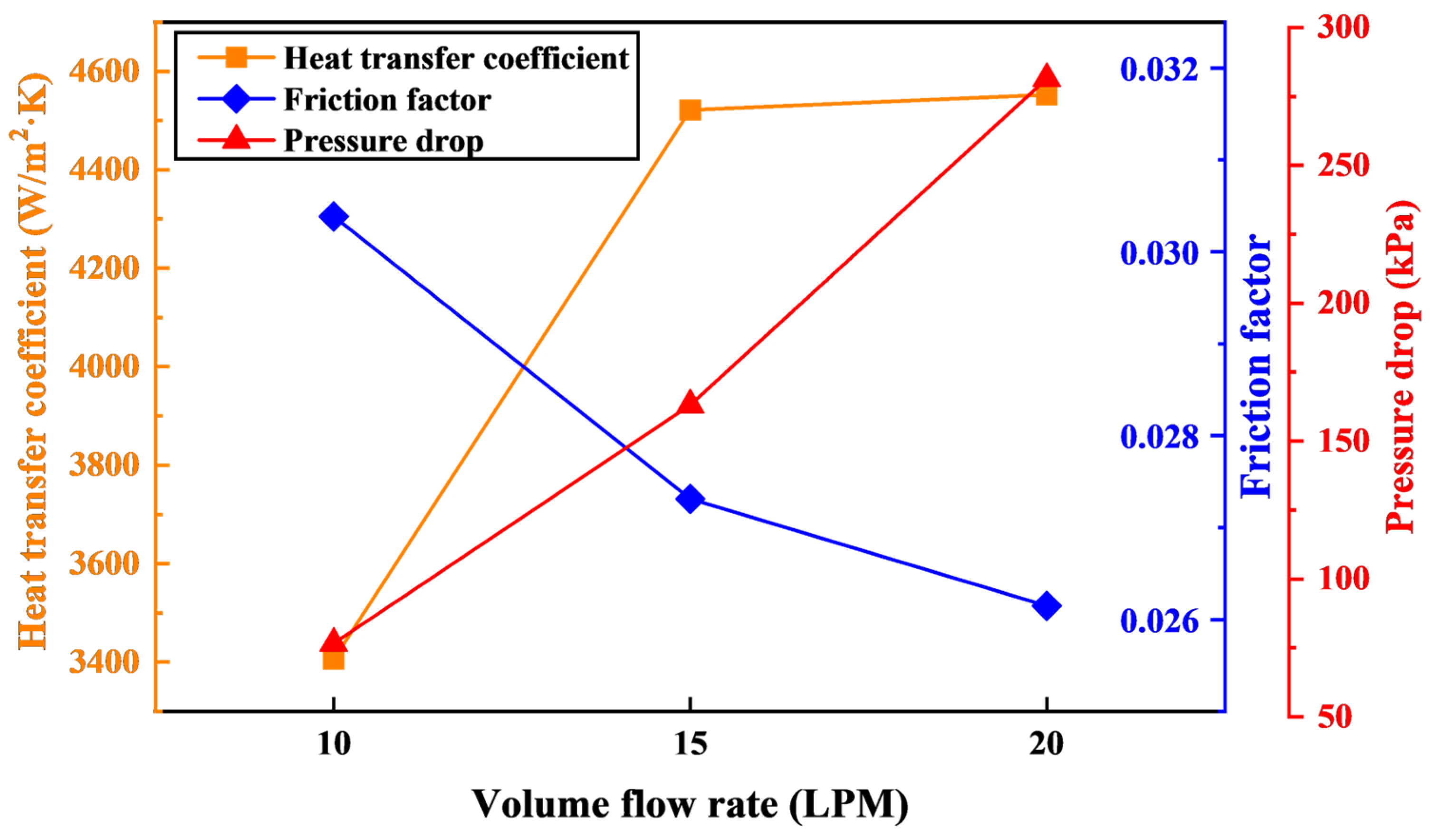
3.2.2. Heat Transfer Coefficient, Friction Factor, and Pressure Drop
The influence of the coolant oil volume flow rate on the HTC, friction factor, and pressure drop is shown in
Figure 12. The findings indicated a positive correlation between the HTC and the coolant oil volume flow rate, meaning that an increase in flow rate enhances convective heat transfer efficiency. Specifically, when the coolant oil volume flow rate increased from 10 LPM to 15 LPM, the HTC increased from 3406.08 W/m
2·K to 4521.48 W/m
2·K, demonstrating a strong enhancement in heat transfer performance. This increase can be attributed to the rise in the Reynolds number as the flow rate increases, which leads to higher turbulence intensity and enhances the HTC. This phenomenon allows for more efficient heat dissipation from the motor components. However, the HTC showed a relatively limited increase from 4521.48 W/m
2·K to 4552.20 W/m
2·K with a further increase in coolant oil volume flow rate from 15 LPM to 20 LPM, respectively. This behavior may be due to the phenomenon of heat transfer efficiency reduction in convective heat transfer at higher coolant flow rates and reaching a critical state. Specifically, at higher coolant flow rates, although the turbulence and convective interaction between the coolant and the heated surfaces initially increased, the improvement became insignificant beyond a certain threshold. At a coolant oil volume flow rate of 20 LPM, although the coolant velocity increased, the contact time of the coolant on the heated surfaces decreased. This shorter interaction time limited the heat absorption capacity per unit of coolant, thus limiting the increase in HTC value. Therefore, the HTC benefit of increasing the coolant oil volume flow rate from 15 LPM to 20 LPM is limited compared to the initial increase from 10 LPM to 15 LPM.
The effect of coolant oil volume flow rate on the friction factor and pressure drop is depicted in
Figure 12. As the volume flow rate increased from 10 LPM to 20 LPM, the friction factor decreased, while the pressure drop increased. Specifically, the friction factor decreased from 0.03 to 0.026, while the pressure drop increased from 76.68 kPa to 281.41 kPa when the volume flow rate increased from 10 LPM to 20 LPM, respectively. This counterintuitive behavior can be attributed to the interplay between fluid dynamics and the flow characteristics of the coolant oil. The decrease in the friction factor is primarily due to the higher flow velocity, which reduces the resistance to flow within the cooling channels. As the flow rate increases, the coolant oil experiences less resistance in terms of internal friction, leading to a lower friction factor. However, despite the reduction in friction, the pressure drop increases with the increased flow rate. This increase in pressure drop is a result of the elevated velocity, which leads to greater turbulence and higher shear stress on the channel walls. As the velocity increases, the energy required to overcome the hydraulic resistance also rises, thus leading to a higher pressure drop across the system. Therefore, while the friction factor decreases with increasing flow rate, the resulting pressure drop is a consequence of the enhanced velocity and turbulence within the system, demonstrating the complex relationship between the flow rate, friction, and pressure drop in the hybrid direct–indirect oil cooling system.
These findings highlight the trade-off between improved heat transfer performance and increased hydraulic resistance in hybrid direct–indirect oil cooling systems. While a higher coolant oil volume flow rate enhances cooling efficiency, it also results in greater pressure drop, which could lead to higher energy consumption for the pumping system. Therefore, an optimal balance between thermal performance and hydraulic efficiency must be determined to ensure effective cooling without excessive energy penalties.
3.2.3. Performance Evaluation Criteria
The PEC were analyzed to determine the optimal coolant oil volume flow rate for the hybrid direct–indirect oil cooling system. The variation in the PEC value for different coolant oil volume flow rates is presented in
Figure 13. The PEC values corresponding to coolant oil volume flow rates of 10 LPM, 15 LPM, and 20 LPM were 1, 1.37, and 1.40, respectively. These values highlight the trade-off between thermal performance and hydraulic efficiency, emphasizing the importance of selecting an appropriate coolant oil flow rate for effective motor cooling. Although the 20 LPM coolant oil volume flow rate resulted in a higher pressure drop compared to the 10 LPM case, it provided the most efficient thermal management, maintaining the lowest maximum temperatures for the winding, stator and motor housing. As a result, the highest PEC value (1.40) was achieved at 20 LPM, indicating superior heat dissipation efficiency despite the increased hydraulic resistance. This suggests that the enhanced convective heat transfer and improved cooling effectiveness at higher flow rates outweigh the negative effects of pressure drop. Conversely, while the 10 LPM coolant oil volume flow rate maintained the lowest pressure drop, it exhibited the worst thermal performance, leading to the highest winding, stator, and housing temperatures among the studied cases. This reduction in heat dissipation efficiency resulted in the lowest PEC value (1.0), demonstrating that insufficient coolant circulation compromises the effectiveness of the cooling system.
Based on these findings, a coolant oil volume flow rate of 20 LPM is proposed as the optimal operating condition for further numerical simulations to assess the cooling performance of the hybrid direct–indirect oil cooling system for the electric motor. This selection ensures maximized heat dissipation while maintaining acceptable system efficiency, contributing to the development of an optimized thermal management strategy for high-performance electric motors.
3.3. Effect of Different Motor Heat Losses
To ensure optimal performance and operational safety, the maximum operating temperature of the motor must be maintained below 180 °C [
27]. Exceeding this threshold can lead to the thermal degradation of insulation materials, reduced efficiency and potential motor failure. Therefore, maintaining an effective cooling strategy is critical for enhancing the reliability and longevity of the motor. In this study, the cooling efficiency of the hybrid direct–indirect oil cooling system was evaluated under different motor heat loss levels, including 2.6 kW, 4 kW, 6 kW, and 8 kW. The optimized cooling configuration consisting of a spray hole diameter of 1.7 mm and a coolant oil volume flow rate of 20 LPM was implemented to assess its effectiveness in maintaining acceptable motor temperatures. The simulations were conducted with an inlet temperature of ATF SP-4 oil and an initial motor temperature set at 25 °C to ensure consistency in the boundary conditions across all cases. The key parameters analyzed included the maximum temperature of the winding, stator and motor housing, HTC and Nusselt number. By evaluating these thermal characteristics, this study aims to determine the effectiveness of the hybrid direct–indirect oil cooling system in handling increasing thermal loads and capacity for preventing overheating under high-power operating conditions.
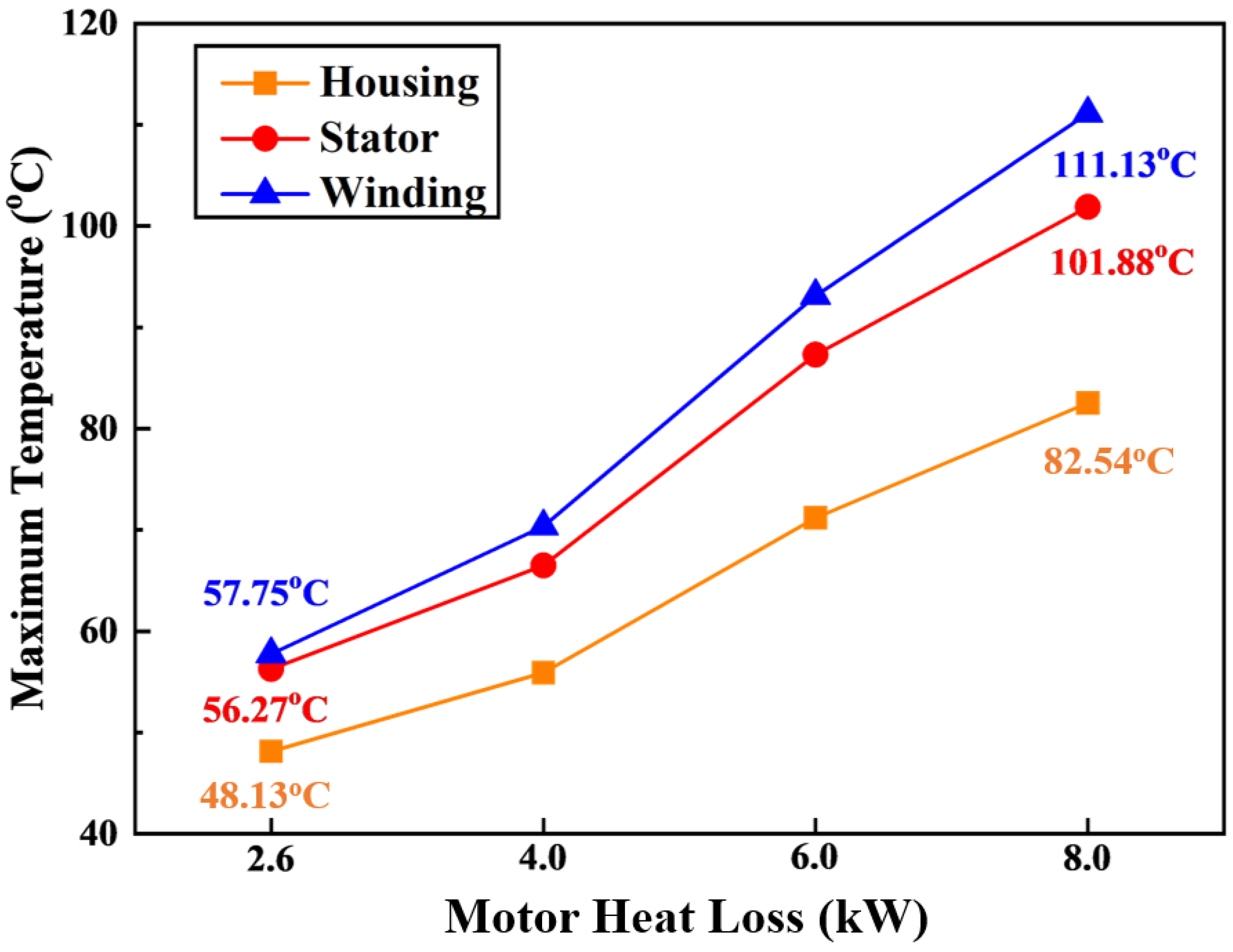
The effect of motor heat loss on the maximum temperature of the winding, stator and motor housing is presented in
Figure 14. The findings indicate that as the motor heat loss increases, the operating temperature of the motor components also rises significantly, reflecting the direct correlation between power input and heat generation. Specifically, when the motor heat loss increased from 2.6 kW to 8 kW, the maximum winding temperature rose from 57.75 °C to 111.13 °C, representing a substantial temperature increase due to the greater heat loss of the motor. Similarly, the motor housing and stator temperatures followed the same trend, increasing from 48.13 °C to 82.54 °C and from 56.27 °C to 101.88 °C in the same motor heat loss range. This temperature rise is attributed to the increased heat dissipation requirements, as higher motor power leads to greater heat loss in the form of heat, which must be effectively managed to maintain stable motor operation.
Figure 15 presents the distribution of temperatures across various components of the motor, including the winding, stator, and housing under different motor heat loss conditions. As the heat loss increases, the temperatures of the winding, stator and housing rise, highlighting the critical role of effective thermal management. These results demonstrated that the hybrid direct–indirect oil cooling system can maintain temperature levels within acceptable limits even under high heat losses.
The above research results demonstrates that, although the heat loss of the motor increased significantly, the hybrid direct–indirect oil cooling system provided superior cooling performance and maintained the operating temperature of the motor components within the optimal range (below 180 °C). Even at the maximum power level of 8 kW, the cooling system ensured that excessive overheating was prevented, highlighting its efficacy in handling high thermal loads. These results confirm that the optimized hybrid direct–indirect oil cooling configuration provides a reliable and efficient thermal management solution, making it a promising approach for next-generation high-power electric motors.
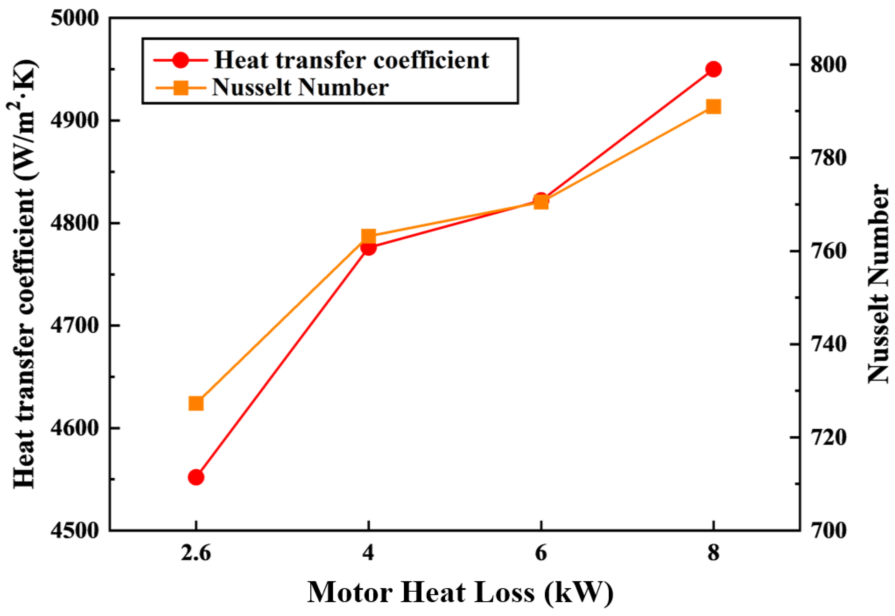
The variation in the HTC and Nusselt numbers with different motor heat loss levels is shown in
Figure 16. The findings indicated that both HTC and Nusselt numbers exhibit an increasing trend as motor heat loss increases. Specifically, when the motor heat loss increased from 2.6 kW to 8 kW, the HTC increased from 4552 W/m
2·K to 4950 W/m
2·K, while the Nusselt number increased from 727.28 to 790.99. This trend can be attributed to the enhanced heat absorption facilitated by the direct oil spray cooling mechanism. As the heat loss increases, a greater amount of thermal energy is dissipated from the winding and stator. Since the oil is evenly distributed over these surfaces, the convective heat transfer mechanism becomes more effective, resulting in an increased heat transfer rate. Consequently, the HTC and Nusselt numbers rise due to the higher thermal energy exchange between the motor components and the coolant oil, which maintains effective convective cooling at elevated heat loss levels. Therefore, this study demonstrates the superior cooling efficiency of the hybrid direct–indirect oil cooling method. This further strengthens its applicability to next-generation electric motors with increasing power demand and high heat loads.
4. Conclusions
This study investigated the heat transfer characteristics of a hybrid direct–indirect oil cooling system for electric motors, focusing on the effects of spray hole diameter, coolant oil volume flow rate, and motor heat loss. Through numerical simulations, heat transfer characteristics, including maximum winding, stator and housing temperatures, HTC, friction factor, pressure drop, and PEC, were analyzed to determine the best cooling configuration. The main conclusions of the current study are outlined below.
The spray hole diameter significantly affects the heat transfer characteristics of a hybrid direct–indirect oil cooling system. Among the tested configurations, the spray hole diameter of 1.7 mm achieves the best trade-off between cooling and energy consumption performances with the highest PEC value. Therefore, the spray hole diameter of 1.7 mm is proposed as the optimal configuration in the current hybrid direct–indirect oil cooling system.
As the flow rate increased from 10 LPM to 20 LPM, the maximum temperature of the winding, stator and motor housing decreased by 22.05%, 22.70%, and 24.02%, respectively. However, increasing the coolant flow rate also led to a substantial rise in pressure drop from 76.68 kPa to 281.41 kPa. The PEC analysis confirmed that a coolant flow rate of 20 LPM provided the best balance between heat dissipation and energy consumption, making it the optimal operating condition for effective motor cooling.
As motor heat loss increased from 2.6 kW to 8 kW, the maximum temperatures of the stator and the housing rose significantly, with the winding temperature increasing from 57.75 °C to 111.13 °C, the stator temperature increasing from 56.27 °C to 101.88 °C, and the housing temperature increasing from 48.13 °C to 82.54 °C. Additionally, the HTC and the Nusselt numbers showed strong increasing trends. Despite an increase in heat loss, the hybrid direct–indirect oil cooling system successfully maintained all motor component temperatures below the critical limit of 180 °C, demonstrating its capability to effectively manage heat dissipation even under high-power operating conditions.
The findings of this study confirm that the hybrid direct–indirect oil cooling system offers a highly effective thermal management solution for high power density electric motors. These findings contribute to the development of an advanced cooling strategy for electric motors, ensuring improved thermal management and long-term reliability in high-performance electric vehicle applications. Future studies will focus on evaluating the performances of electric motors with a proposed hybrid oil cooling system under various driving duty cycles followed by optimization of the geometrical and operating parameters.


