1. Introduction
The geometric profile and penetration depth of intersecting line welds in large double-curvature penetration structures exhibit spatial dependency. In thick-walled components with extensive groove dimensions, the substantial cross-sectional area requires systematic multi-layer multi-pass deposition. Conventional manual welding has several issues. These include high labor intensity, low productivity, and inconsistent joint quality caused by differences in operator skills. As a result, robotic welding systems have become a viable technological solution [
1,
2]. The core technical challenge in robotic welding implementation lies in trajectory planning for the welding torch [
3,
4]. Currently, robotic welding systems predominantly employ three operational paradigms: teach-and-repeat, offline programming, and sensor-assisted guidance [
5].
Conventional teach-and-repeat approaches exhibit limitations in programming large intersecting line welds with variable profiles, which are characterized by labor-intensive teaching processes, low efficiency, and trajectory instability due to human operator dependencies. Sensor-driven autonomous trajectory planning has emerged as a prominent research frontier, with two dominant technical paradigms: line-structured light guidance systems [
6,
7] and raster-stereo vision configurations [
8].
In the field of line-structured light guidance systems, J. Fan et al. [
9] developed a laser vision sensor with additional Light Emitting Diode (LED) lights for narrow seam welding, which solves the challenges of initial point alignment and seam tracking caused by insignificant laser stripe deformation in narrow seams through extracting weld feature points combined with visual models to obtain 3D coordinates. Researchers led by J. Gao et al. [
10] employed line-structured light technology to accurately extract weld position and gap features, providing crucial support for autonomous sensor path planning. Y. Zou et al. [
11] proposed a robotic seam tracking system integrating lightweight segmentation network design with ADMM-structured pruning, ensuring stable torch operation under strong interference. Wang et al. [
12] established a structured light vision system capable of identifying initial welding points for fillet welds. Liu et al. [
13] developed a novel sensor that locates initial weld points using combined information from crossed and parallel laser stripes, enhancing system adaptability to irregular workpieces.
Regarding line-structured light guidance systems, to overcome the inefficiency of conventional teaching programming, Zhang’s team [
14] developed a robot path-planning approach based on 3D visual guidance. Geng et al. [
15] obtained welding paths through multi-view point cloud stitching for complex main-intersection pipelines. Fang [
16] proposed a welding trajectory-planning method combining non-rigid point cloud registration with 3D model offline processing. Liu et al. [
17] employed deep learning networks combined with symbolic splicing to plan welding trajectories. Ma et al. [
18] proposed a deep neural network-based method for weld type recognition and initial point guidance, significantly enhancing the intelligence level of welding robots.
Researchers worldwide have carried out numerous studies on two methodologies—line-structured laser guidance and raster-based stereoscopic vision—within the domain of self-planning welding path sensors. The former focuses on seam tracking and initial weld point localization. However, its detection capabilities are largely limited to specific welding conditions, showing inadequate adaptability to complex and diverse working scenarios. Additionally, the complex detection equipment at the torch end is susceptible to arc light and spatter interference, resulting in system instability. The latter primarily involves constructing vision systems for different workpieces to plan paths, acquiring surface morphology information for welding trajectory planning. However, when handling irregular workpiece placement and environmental interference, technical immaturity issues persist, requiring improved adaptability to diverse scenarios. To summarize, sensor guidance technology remains relatively immature with poor adaptability.
Related Work
Using robot offline programming software for welding path planning of large saddle-shaped seams proves to be a highly effective approach. The template matching-based weld recognition method simplifies complex image processing procedures by constructing Computer-Aided Design (CAD) models and comparing them with point cloud data to obtain required weld seams and their characteristics.
Geng et al. [
19] proposed a 3D vision-based method for robotic welding of medium-thickness plates, using improved RANSAC to fit point cloud planes and extract weld seams via intersecting line analysis. The approach integrates geometric feature-based seam extraction for three structural models, combined with welding path planning according to seam spatial structure and a dihedral-based posture planning method, enabling teach-free automation. While effective for medium-thickness plate structures, the method’s multi-layer multi-pass path-planning algorithm relies on predefined geometric constraints, limiting flexibility in adapting to complex, variable cross-sectional weld profiles.
Curiel et al. [
20] introduced a symmetry-driven algorithm for tool path selection in robotic welding, leveraging profile scanning and CAD model integration. This method optimizes torch orientation and bead placement for thick-walled components with non-uniform grooves, enhancing efficiency in gas metal arc welding. However, their approach assumes symmetric joint configurations, which may not generalize to the asymmetric multi-layer multi-pass welds typical of large intersecting line workpieces.
Arko and Jezeršek [
21] presented an automated calibration procedure for 3D scanner-robot systems, achieving sub-0.06 mm accuracy through Powell’s optimization algorithm. This method ensures precise alignment between the scanner and robot coordinate systems, which is critical for adaptive welding of thick pipes and thin sheets. While their calibration framework enhances system stability, it does not explicitly address geometric feature extraction from scanned data.
Lei et al. [
22] proposed a row–column grayscale segmentation method to extract cross-sectional weld bead morphology, enabling quantitative assessment of contour and area with <10% error. This technique complements our trajectory-planning pipeline by providing post-weld quality insights. However, their focus is on offline analysis rather than real-time path adaptation.
Zhao et al. [
23] advanced the field by specifically targeting intersecting pipe structures, introducing a planning algorithm that accounts for spatial geometric constraints during multi-layer deposition. Their approach emphasizes kinematic optimization and groove profile analysis to generate collision-free paths, demonstrating improved accuracy for symmetric intersecting joints compared to traditional teach-and-repeat methods. However, this methodology exhibits limitations in handling asymmetric profiles and manufacturing tolerances, as it relies on idealized CAD models for initial path generation. In scenarios with significant assembly deviations, which are common in large-scale weldments like shipbuilding components, pre-defined geometric assumptions may lead to trajectory mismatches, compromising weld quality.
Neto and Mendes [
24] investigated the data-mapping process from virtual CAD models to real-world environments for automated robot path and program generation. Wang et al. [
25] innovatively integrated CAD model information with visual data, establishing new perspectives for enhancing the flexibility and reliability of spot-welding robot systems. Fu et al. [
26] proposed a template-based identification framework for aerospace components that integrates Hausdorff distance metrics with Monte Carlo simulations, optimizing template candidate screening processes. The research team under Zheng et al. [
27] introduced an integrated offline programming strategy that synergizes CAD modeling, visual perception, and their mutual interactions, markedly enhancing robotic welding performance in terms of productivity, accuracy, and adaptability for intricate workpieces.
However, conventional offline programming methodologies exhibit three critical limitations:
Reliance on idealized CAD models, neglecting actual manufacturing tolerances during path generation;
Omission of assembly-induced positional discrepancies between components;
Suboptimal bead-sequencing strategies in multi-layer multi-pass welding, especially when handling variable-profile joint configurations.
These issues are particularly pronounced in large-scale weldments for non-high-precision applications such as shipbuilding and construction [
28,
29,
30], where manufacturing tolerances vary substantially with production techniques and temporary tack-welded assemblies introduce stochastic positional variations. Consequently, robot trajectories generated from nominal CAD models prove non-executable in practical welding operations.
To address these challenges, a handheld 3D scanning system with superior metrological performance is implemented, outperforming raster-stereo vision systems in both accuracy and angular adaptability. An adaptive multi-layer multi-pass deposition algorithm is proposed, integrating model slicing, geometric feature extraction, and projective transformation-based bead sequencing for variable-profile groove welding. Sensor-derived 3D digital models enable more accurate path generation than conventional CAD-based offline programming, particularly for components with manufacturing variances. The proposed methodology extends the applicability of offline programming systems, demonstrating critical advancements in robotic welding applications with geometric uncertainties.
2. Materials and Methods
Figure 1 illustrates the proposed path-planning framework, which operates through eight sequential processing stages:
Acquisition of as-built component geometry using a handheld 3D scanning system, generating STL models, dense point clouds, and fiducial marker coordinates for spatial registration;
Implementation of RANSAC-based cylindrical fitting to establish the central branch pipe axis, followed by Euclidean distance thresholding for point cloud segmentation. This preprocessing stage eliminates geometrically irrelevant data points, optimizing computational load for subsequent operations;
Generation of a cutting plane around the pipeline axis and reconstruction of the topology of the disordered STL mesh, followed by calculation of the intersection of the cutting plane and the STL model to obtain the groove section;
Accurate extraction of groove feature points by straight line fitting and compensation of missing feature points by spatial interpolation of adjacent cross-sectional data;
To solve the geometric asymmetry and manufacturing tolerance problems of intersecting welds, a multi-layer and multi-pass adaptive arrangement of welds is implemented based on template affine projection transformation. This method can adapt to the changes in the cross-sectional profiles of different welding areas while maintaining the consistency of the weld pattern. This will be described in detail in
Section 2.3;
According to the planned cross-sectional sequence, the welding trajectory is generated according to the path on the groove and then transferred to the offline programming environment. Finally, an executable program is generated;
Virtual simulation motion is performed through kinematic simulation, which can verify the robot’s accessibility and eliminate the risk of collision before actual application;
To carry out coordinate system transformation, this paper generates corresponding user coordinate systems in the actual robot system and offline programming system according to the scanning positioning points and generates robot execution files in this coordinate system to complete the path planning of multi-layer and multi-pass offline programming of a large saddle-shaped welding workpiece.
The core technologies of this paper include STL model slicing, geometric feature extraction, and adaptive path planning based on template affine projection, which constitute the important components of the proposed 3D scanning-driven welding framework.
2.1. Scanned STL Model Slicing
To efficiently extract groove profiles from cutting planes, STL model slicing is implemented. The inherent disorder of triangular facet representations necessitates computationally intensive operations, including full facet traversal for intersection detection and subsequent segment ordering—processes that are particularly inefficient for dense scanning-derived STL models. Scanning-acquired STL models with ultra-dense facet distributions (typically in the tens of millions) exacerbate computational complexity, as brute-force traversal algorithms yield unordered intersection segments with O(n) time complexity. To address these issues, the following topological optimization was implemented on the STL structure, as illustrated in
Figure 2.
The optimization algorithm runs through five steps, as shown in
Figure 3:
Read the STL model and optimize the topology structure: First, the unordered triangles will be sorted into point set, line set, face set. The point object contains x, y, and z coordinate information and a flag flagPoint used to record the positional relationship with the plane; the edge object contains the two vertex pointers pt1 and pt2 that constitute the edge and the pointers face1 and face2 of the two triangles to which the edge belongs, as well as a flag flagEdge used to mark whether it intersects with the plane. Each face object contains the pointers edge_AB, edge_AC, and edge_BC that constitute the three edges of the triangle.
Determine the positional relationship: Traverse the point set and implement the CalPointFlag method in sequence to calculate the positional relationship between all points and the plane (i.e., on the plane, in the plane, and under the plane) and record them.
Generate the intersected edge set: Traverse the line set and implement the CalEdgeFlag method in sequence to calculate whether the line intersects with the plane. If the flagPoint attribute values of the two endpoints of the line are different, it is determined to be intersecting.
Construct an ordered intersected edge list: Randomly find an intersecting edge, use the FindAnotherInsectionEdge method of its member face1, find another edge in face1 that intersects with the plane, and record it as edgeNew. Then, use the FindAnotherInsectionFace method of edgeNew to find one of the two triangles to which edgeNew belongs that is not face1. Repeat this cycle until this edge is a boundary, and obtain an edge chain. Repeat the above steps until all intersecting edges have been calculated, and obtain multiple edge chains.
Obtain the sequence of intersection lines: Traverse the edge chain, calculate the intersection points of the edge and the triangle, and connect the intersection points in sequence to obtain a contour.
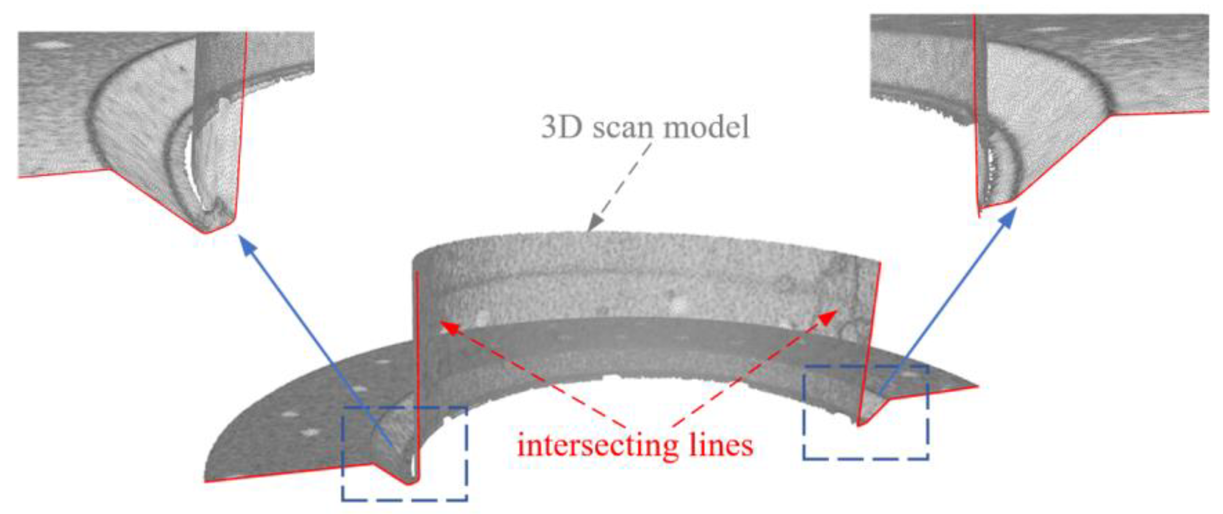
With this method, only the triangles that actually intersect the slice surface need to be traversed during one slicing process. At the same time, the obtained path segments are ordered, which is convenient for subsequent processing. The slicing effects on workpiece STL models through these steps are shown in
Figure 4, the greyscale parts in the picture are the scanned model, and the red line is the calculated intersection line.
In order to quantitatively describe the efficiency of the algorithm, the actual slicing time and effect of three STL models with different densities are statistically analyzed with or without topological structure optimization, as shown in
Table 1. It can be seen that topological structure optimization can significantly reduce the slicing time. When multiple slicing operations are performed on a model with a large number of triangles, the calculation time can be significantly shortened.
2.2. Feature Point Identification
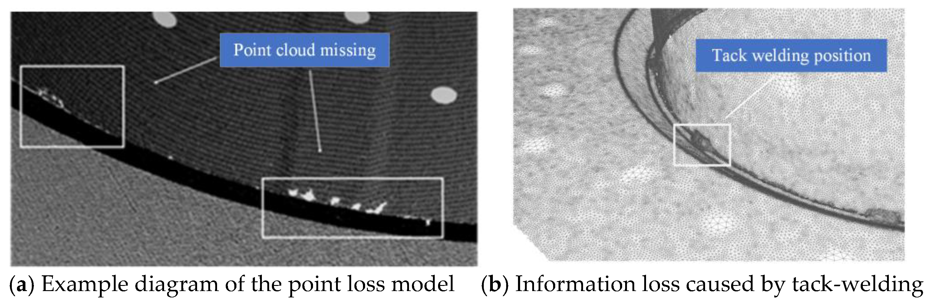
After obtaining cross-sectional contours, geometric feature identification is required for subsequent multi-layer multi-pass bead arrangement. For intersecting line welds, the narrow gap relative to the workpiece and highly reflective machined groove surfaces lead to scanning data loss near grooves when using handheld 3D scanners. Additionally, temporary tack-welding on large components causes groove information loss, as shown in
Figure 5.
Therefore, to achieve more accurate and stable feature point localization, this study employs least squares fitting of groove contours rather than inflection point detection through segment slope variations.
Figure 6 defines four characteristic points (Pt
1, Pt
2, Pc
1, Pc
2), and the intersection line welding groove is approximated by a quadrilateral.
The definition and fitting procedures for feature points are as follows:
Generate points with uniform distance distribution on the cross-sectional contour composed of ordered line segments.
First, calculate the equation of the straight line at the intersection of the cross-section and the branch pipe, use the Hough line transform algorithm to extract the straight line in the cross-sectional contour, and select the straight line l according to the angle range between the straight line and the cylinder axis of the branch pipe.
Calculate the distance from all other points on the contour to the straight line l. According to the design size of the groove, it is easy to find three distance intervals to ensure that the points in the corresponding distance intervals are at the main pipe, the main area of the groove, and the tongue area of the groove. Then, use the least squares method to fit the straight line to obtain l1, l2, and l3 respectively.
Calculate intersections of l1–l2 and l2–l3 as Pt1 and Pt2. Project these points onto line l to obtain Pc1 and Pc2. The quadrilateral formed by these four points effectively describes the groove morphology.
In order to mitigate the disappearance or error of feature positioning due to missing scan information, spline-based interpolation is used to correct data gaps and position errors. The final feature recognition results shown in
Figure 7 demonstrate robust performance, and the groove features can be stably detected despite the presence of point cloud defects and spot-welding interference.
The definition and fitting procedures for feature points are as follows:
Generate points with uniform distance distribution on the cross-sectional contour composed of ordered line segments.
First, calculate the equation of the straight line at the intersection of the cross-section and the branch pipe, use the Hough line transform algorithm to extract the straight line in the cross-sectional contour, and select the straight line l according to the angle range between the straight line and the cylinder axis of the branch pipe.
Calculate the distance from all other points on the contour to the straight line l. According to the design size of the groove, it is easy to find three distance intervals to ensure that the points in the corresponding distance intervals are at the main pipe, the main area of the groove, and the tongue area of the groove. Then, use the least squares method to fit the straight line to obtain l1, l2, and l3, respectively.
Calculate intersections of l1–l2 and l2–l3 as Pt1 and Pt2. Project these points onto line l to obtain Pc1 and Pc2. The quadrilateral formed by these four points effectively describes the groove morphology.
In order to mitigate the disappearance or error of feature positioning due to missing scan information, spline-based interpolation is used to correct data gaps and position errors. The final feature recognition results shown in
Figure 6 demonstrate robust performance, and the groove features can be stably detected despite the presence of point cloud defects and tack-welding interference.
2.3. Multi-Layer Multi-Pass Bead Arrangement and Planning Algorithm for Asymmetric Grooves
As shown in
Figure 8, the groove angles (∠A, ∠B, ∠C) vary across different positions of intersecting line welds. This requires weld torch posture to be planned differently for robotic welding at various spatial locations on the saddle-shaped surface.
The saddle-shaped geometry induces depth variations along the weld path, resulting in continuously changing cross-sectional profiles and areas, as shown in
Figure 9. Comparative cross-sectional views at positions A-A, B-B, and C-C reveal significant profile differences, necessitating multi-pass weld path planning with multiple layers on the varying cross-sections.
Current automatic planning algorithms (with constant height and constant area) use deposit height and volume to generate paths. However, complex spatial welds that require all-position welding processes usually rely on empirical weld bead arrangements derived through trial and error. According to the above analysis, the cross-sectional shapes of the grooves at different positions of saddle welds are not strictly equal, that is, the weld bead on the planned coordinate system cannot be mapped to the actual groove position only through rigid transformations such as rotation and translation. This study introduces an adaptive planning algorithm based on a template affine projection transformation that can be determined by engineers, which can adapt to cross-sectional changes in multi-layer and multi-pass weld workpieces.
Figure 10 compares rigid transformation (rotation/translation) with affine projection results. Rigid transformations fail to accommodate groove shape changes, while affine projection maintains bead pattern similarity. The specific implementation steps of the algorithm are as follows.
First, a local coordinate system X-O-Y is established on groove cross-sections (
Figure 11). Characteristic points pt
1(
x1,
y1), pt
2(
x2,
y2), pc
1(
x3,
y3), pc
1(
x4,
y4) are determined from K-type groove dimensions. Beads are uniquely defined by 2D coordinates and angles relative to the X-axis. Since the groove feature points (Pt
1, Pt
2, Pc
1, Pc
2) obtained by slicing and fitting are three-dimensional coordinates in the three-dimensional coordinate system of the model, and the template is established in a two-dimensional plane, the coordinate dimensions are different and cannot be directly transformed through transmission. To this end, the groove section should be rotated to a surface parallel to the X-O-Y plane in the three-dimensional coordinate system, so that its z-axis value becomes the same value. Ignoring the dimension of the z-axis, this transformation matrix can be calculated through the normal of the groove section and will not be repeated here. Suppose the coordinates of the groove feature points after rotation transformation are Pt
1(
x1′,
y1′,
C), Pt
2(
x2′,
y2′,
C), Pc
1(
x3′,
y3′,
C), Pc
1(
x4′,
y4′,
C), where C is an arbitrary constant. Let
H denote the affine transformation matrix from the template coordinate system to the groove coordinate system, which can be expressed as
The matrix components are determined through linear system solution:
Vector-described beads in spatial groove sections require additional direction parameters to fully define the robot pose. In offline programming systems, a coordinate system (tag point) uniquely defines the robot pose. This study uses section plane normals as the Y-axis, bead vectors as torch axes, and vector origins as coordinate system origins.
Figure 12 shows (a) a 2D bead pattern template; (b) projection-mapped beads on actual grooves; and (c) corresponding tag points in offline programming.
2.4. Coordinate System Calibration
Since the model is acquired by a handheld 3D scanner, all current operations are performed in the model coordinate system established based on the camera coordinate system of the first frame scan, and the robot lacks knowledge of the actual position of the workpiece. This paper establishes the corresponding user coordinate system in the workpiece and the robot system by scanning the positioning markers, so that the robot can find the workpiece position.
The robot user coordinate system is calibrated using the three-point calibration method, as shown in
Figure 13. Three label points are selected on the workpiece surface as the origin, a point on the X-axis of the user coordinate system, and a point on the X-O-Y plane. During the calibration process, the welding gun direction remains unchanged to minimize the tool coordinate system error. The three-point calibration is completed at the center of the welding wire contact marker point, thereby establishing the user coordinate system in the robot system.
On the model, three corresponding points P1, P2, and P3 are selected as the origin, X-axis point, and X-O-Y plane point of the user coordinate system.
The unit vectors for the user coordinate system’s X, Y, and Z axes are calculated as follows:
where
,
,
are vectors of the three tag points in the model coordinate system, and
,
are unit vectors of the user coordinate system’s axes. The transformation matrix from user coordinate systems to camera coordinates is
Consequently, the transformation from model coordinates
to user coordinates
follows Equation (5):
Figure 14 compares coordinate systems before/after transformation. Paths generated in this coordinate system can be directly converted into robot-executable programs.
3. Experiment and Discussion
The experimental system is shown in
Figure 15. The traveling mechanism is composed of two 9-degrees-of-freedom KUKA-R1610 manipulators from KUKA Robotics (Shanghai) Co., Ltd., Shanghai, China, with the workpiece placed in the middle position between the two robots. During actual welding, the two robots perform double-sided welding simultaneously. The selected handheld scanner is the ZhongGuan Scan 717 from Wuhan ZhongGuan Automation Technology Co., Ltd., Wuhan, China, featuring a scanning accuracy of 0.03 mm, as illustrated in
Figure 16. The large-scale pipe–pipe intersecting workpiece containing intersecting line welds is shown in
Figure 17, with the main pipe diameter being 10 m and the branch pipe diameter 0.3 m.
The offline programming system V1.0 was independently developed using C++ and Qt, integrating functions of model preprocessing, STL model slicing, groove feature recognition, and multi-layer multi-pass arrangement. As illustrated in
Figure 18, the system architecture primarily consists of three modules: model processing, planar weld bead layout, and robotic simulation motion.
3.1. Verification Experiment for Multi-Layer Multi-Pass Layout
To verify the algorithm’s efficacy, a comprehensive test of its workflow was conducted. Initially, the RANSAC cylinder fitting algorithm was used on the scanned model to reconstruct the branch pipe cylinder, as depicted in
Figure 19. Following that, the STL model’s topological structure was reconstructed, and cutting planes were generated at 1° intervals around the branch pipe’s central axis. Geometric feature points of the groove were identified on the sliced cross-sections, and a bead layout template was designed in the planar space. Welding paths were generated via projective transformation, with the template and path label points illustrated in
Figure 20. Finally, motion simulation was performed in the offline programming system, as shown in
Figure 21, and an executable file was generated with spline interpolation commands between path points.
Corresponding user coordinate systems were established in both the offline programming and physical robot systems using identical marker points. Weld bead trajectories and poses were converted from the world coordinate system to the user coordinate system, and robot-executable programs were generated for welding operations. The planned positions and poses of multi-layer multi-pass welds are depicted in
Figure 22. Observation shows that the actual robot poses match the planned templates exactly, validating the feasibility of the proposed path-planning algorithm.
3.2. Experimental Verification of System Accuracy
To validate system accuracy, a robot motion trajectory is created along the groove perimeter, where the welding torch’s advancing direction is normal to the cutting plane and its axis is perpendicular to the groove surface. The trajectory transitions from the groove base to the top, rotating 180° around the central axis. Five equally spaced detection points are positioned at 6 o’clock, 4:30, 3 o’clock, 1:30, and 12 o’clock orientations along the path. At each specific position of the manipulator, the distance from the tool tip to the workpiece perimeter is measured. The planned trajectory and detection point layout are illustrated in
Figure 23.
The measurement process and results are shown in
Figure 24 and
Table 2, respectively. For each test point, the average value is taken as the mean deviation of the point by finding three workers to estimate. The results show that all deviations are less than 1.0 mm, indicating that the proposed method meets the positioning accuracy requirements of large intersecting line groove welds. The system error sources include scanning error, robot tool coordinate system calibration error, robot user coordinate system calibration error, robot motion accuracy error, and groove feature extraction error, but the overall error is within an acceptable range.
4. Conclusions
In this study, a handheld 3D scanner was used to scan a pipe-to-pipe intersecting workpiece containing large-sized intersecting line welds to obtain an actual STL model of the assembled workpiece. The RANSAC cylindrical fitting method was used to fit the model and extract the linear equation of the central axis of the branch pipe. On this basis, the model was simplified and sliced circumferentially, and the geometric feature points of the actual weld groove were extracted according to the intersection line. Using template transmission projection, an adaptive-shape variable cross-section multi-layer multi-pass path-planning algorithm was implemented. Finally, the transformation matrix between the model coordinate system and the user coordinate system was derived using the marked positioning points on the workpiece surface, and the robot-executable file was generated. The multi-layer multi-pass arrangement test showed that the robot’s position at the variable cross-section groove was consistent with the planned position, verifying the effectiveness of the proposed algorithm. In addition, an accuracy verification path was generated along the outer edge of the groove. Field measurements showed that the deviation between the robot motion position planned by scanning and groove feature recognition and the actual position was less than 1.0 mm, which met the positioning accuracy requirements of arc welding for large double intersecting groove welds.
This study builds on traditional offline programming. It uses sensor-based online modeling to obtain the actual workpiece model. This model generates accurate welding paths. The approach solves the problem of invalid paths caused by large deviations between nominal CAD models and real workpieces in traditional offline programming. It also expands the application scope of offline programming. With the popularization of reverse modeling technology, the path generation algorithm based on this technology is expected to become an important research hotspot and development trend. However, the feature extraction algorithm proposed in this paper is only for the dual intersecting line model and relies on the threshold based on the standard model size in the feature extraction process, which has certain limitations. Future research will combine deep learning technologies such as PointNet++ to enhance the universality of the algorithm.


