Article

Analysis of Main Roof Mechanical State in Inclined Coal Seams with Roof Cutting and Gob-Side Entry Retaining

1
College of Energy Engineering, Xi’an University of Science and Technology, Xi’an 710054, China
2
Key Laboratory of Western Mine Exploitation and Hazard Prevention Ministry of Education, Xi’an 710054, China
3
Sichuan Xuyong No.1 Coal Mine Co., Ltd., Luzhou 646499, China
*
Author to whom correspondence should be addressed.
Symmetry 2025, 17(5), 723; https://doi.org/10.3390/sym17050723
Submission received: 18 April 2025 / Revised: 6 May 2025 / Accepted: 6 May 2025 / Published: 9 May 2025
(This article belongs to the Section Engineering and Materials)

Abstract

:
The non-uniform deformation and failure phenomena encountered in steeply inclined coal seams during roof-cutting and gob-side entry retaining operations demand urgent resolution. Taking the haulage roadway of the 3131 working face in Longmenxia South Coal Mine as the research background, the theoretical analysis method is adopted to explore the mechanical state of the main roof in inclined coal seams and the design of roadside support resistance. According to the structural evolution characteristics of the main roof, it is divided into four periods. Based on the elastic theory, corresponding mechanical models are established, and the mechanical expressions of the main roof stress and deflection are derived. The distribution characteristics of the main roof’s mechanical state in each zone and the influence law of the coal seam dip angle on the main roof’s mechanical state are studied. This study reveals a critical transition from symmetric to asymmetric mechanical behavior in the main roof structure due to the coal seam dip angle and roof structure evolution. The results show that, in the absence of roadside support, during the roadway retaining period, the upper surface of the main roof is in tension, and the lower surface is under compression. The stress value increases slowly from the high-sidewall side to the middle, while it increases sharply from the middle to the short-sidewall side. Under the inclined coal seam, as the dip angle of the coal and rock strata increases, the component load perpendicular to the roof direction decreases, and the roof deflection also decreases accordingly. On this basis, the design formula for the roadside support resistance of gob-side entry retaining with roof cutting in inclined coal seams is presented, and the roadside support resistance of the No. 3131 haulage roadway is designed. Building upon this foundation, a design formula for roadside support resistance in steeply inclined coal seams with roof-cutting and gob-side entry retaining has been developed. This formula was applied to the No. 3131 haulage roadway support design. Field engineering tests demonstrated that the maximum roof-to-floor deformation at the high sidewall decreased from 600 mm (unsupported condition) to 165 mm during the entry retaining period. During the advanced influence phase of secondary mining operations, the maximum deformation at the high sidewall was maintained at approximately 193 mm.

1. Introduction

In the southwestern region of China, inclined coal seams account for up to 80% of the total coal reserves, and most of them are high-quality and scarce coal resources. However, due to the complex occurrence conditions of coal seams and the increasing mining intensity year by year, engineering disasters, such as surrounding rock control, are on the rise [1]. Pillar-less mining technologies, such as gob-side entry retaining with roof cutting, have obvious technical advantages in improving coal recovery rate, optimizing ventilation methods, and alleviating the tight working-face replacement situation [2,3,4], and, thus, are widely used in coal seam mining. Gob-side entry retaining with roof cutting in inclined coal seams is different from that in horizontal coal seams. The stability of the roadway is more affected by mining activities, and both the dip angle of the coal seam and the non-uniform accumulation of gangue will influence the stability of the gob-side entry. Therefore, studying the control of roof strata in gob-side entry retaining with roof cutting in inclined coal seams is of great significance for the safe and efficient mining of inclined coal seams.
In the field of gob-side entry retaining and surrounding rock control in steeply inclined coal seams, numerous scholars have achieved substantial research advancements through theoretical analysis, numerical simulation, and other methodologies. Yu Guangyuan et al. [5] established simplified mechanical models of the surrounding rock in different zones and obtained the requirements for roof support resistance and deformation in different zones. Zhen Enze et al. [6] adopted a new type of gob-side entry retaining technology with roof-cutting and pressure-relief in inclined thick coal seams, and described, in detail, the roadside support system to ensure the roadway effect. Zhang Li et al. [7], in view of the unique characteristics of gangue rolling and accumulation in steeply inclined coal seams, proposed an innovative method for gob-side entry retaining through roof cutting in steeply inclined coal seams. This method can not only overcome the impact of rolling gangue on roadside support but also make the rolled and accumulated gangue serve as roadside support. Wang Hao et al. [8] focused their research on fully-mechanized caving faces in inclined coal seams. Through simulation and analysis under conditions of different coal-seam dip angles, thicknesses, widths of roadside support bodies, and in-roadway support resistances, they studied the dynamic evolution laws of stress and displacement of the surrounding rock of the gob-side entry as the working face advanced, as well as its plastic failure characteristics. Shi Weiping et al. [9] optimized the key parameters of gob-side entry retaining with roof cutting for thick and hard roofs in inclined coal seams through comprehensive methods, and revealed the optimal values of roof-cutting height and angle. Zhu Yongjian et al. [10] found, through research, that the key to the success of gob-side entry retaining in inclined fully-mechanized mining faces lies in optimizing the long-cantilever beam structure of rock block B. By using the roof-cutting and pressure-relief technology, the stress on the roadside support body and the solid coal rib can be effectively reduced, thus solving technical problems. Cao Shugang et al. [11] discovered during their research on gob-side entry retaining in inclined coal seams that there are differences in the roof activities of the air return roadway and the haulage roadway. When retaining the air return roadway, the roadside support resistance decreases as the coal-seam dip angle increases, while the opposite is true for the haulage roadway. Zhang Li et al. [12], through analyzing the roof stability and deformation in different stages of roadway formation by roof cutting in steeply inclined coal seams, found that the surrounding rock stability in the dynamic-pressure section of the retained roadway is the worst, and proposed collaborative support of strengthening support and gangue-blocking support. Yang Jun et al. [13,14], by analyzing the stress and deformation laws of the surrounding rock in the whole cycle of goaf-side entry retaining without coal pillars by roof-cutting and pressure-relief, found that the stability is the worst during the first mining stage in the process of retaining the roadway, and the surrounding rock stress increases significantly, with the most intense deformation of the roadway surrounding rock. Yang Hongyun et al. [15] analyzed the structural evolution of roadway formation by roof cutting of hard roofs, and found that, after roof-cutting and pressure-relief, the roof forms a short-cantilever beam, vertical tensile cracks occur in the deep part of the coal body, and then it rotates and deforms towards the goaf and contacts the cut-off roof collapsed in the goaf to reach equilibrium. Zhu Zhen [16,17], by establishing a model of the movement characteristics of the surrounding rock of the retained roadway, divided the movement characteristics of the gangue in the goaf into the rapid caving stage and the slow compaction stage. The interactions between gangue movement and the support structure are different in different stages. Liu Xiao [18] assumed the roadway as an elastic deformable body, analyzed the stress characteristics of the immediate roof, divided its deformation into five stages, established the mechanical models of the roadway and the immediate roof in each stage, and obtained the relationship between the deformation of the roadway roof and the stiffness of the support system. Hu Jinzhu [19] established an elastic mechanical model of the main roof through analysis, obtained the stress expression of any point on the main roof, and analyzed the stress distribution characteristics and crack evolution laws of the main roof.
The above-mentioned research mainly focuses on aspects such as the construction of mechanical models for gob-side entry retaining with roof cutting and surrounding rock control in inclined coal seams, the optimization of key parameters, the analysis of roof stability and deformation in different stages, and the interaction between the movement of gangue in the goaf and the support structure. However, there is scarce theoretical research on the influence of the dip angle on the stress state and deflection of the main roof. After roof cutting along the goaf, the structural shape of the surrounding rock and the stress distribution of the roof change significantly. Therefore, taking the gob-side entry retaining with roof cutting in the No. 3131 haulage roadway of Longmenxia South Coal Mine as the engineering background, this paper establishes a mechanical model of the main roof structure for gob-side entry retaining with roof cutting in inclined coal seams based on the evolutionary characteristics of the main roof structure. It analyzes the stress and deflection change characteristics of the main roof and explores the influence of laws of the coal-seam dip angle and support resistance on the stability of the main roof structure in gob-side entry retaining with roof cutting.

2. General Situation of No. 3131 Haulage Roadway Roof Cutting and Retaining Engineering

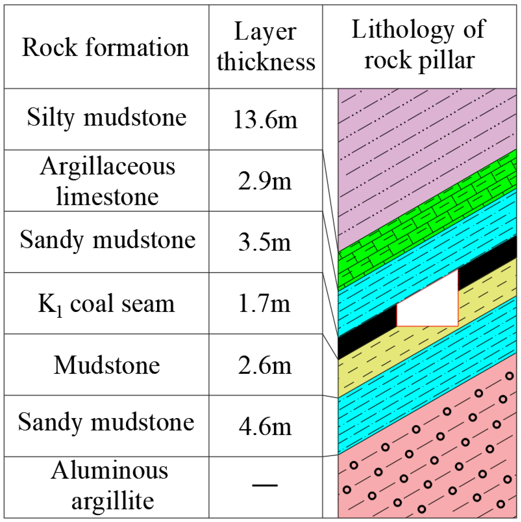
2.1. Overview of Production Geology

Affected by geological structures, the in situ stress of the Longmenxia South Coal Mine is dominated by horizontal stress. The average burial depth of the coal seam is 400 m, and the average dip angle of the coal seam is 30°. The borehole histogram of the working face is shown in Figure 1. Due to the undulation of the coal seam, the roadway section is designed to be irregular. Specifically, the height of the lower side of the excavated section is 2 m, the height of the higher side is 4.0 m, and the span reaches 4.2 m.

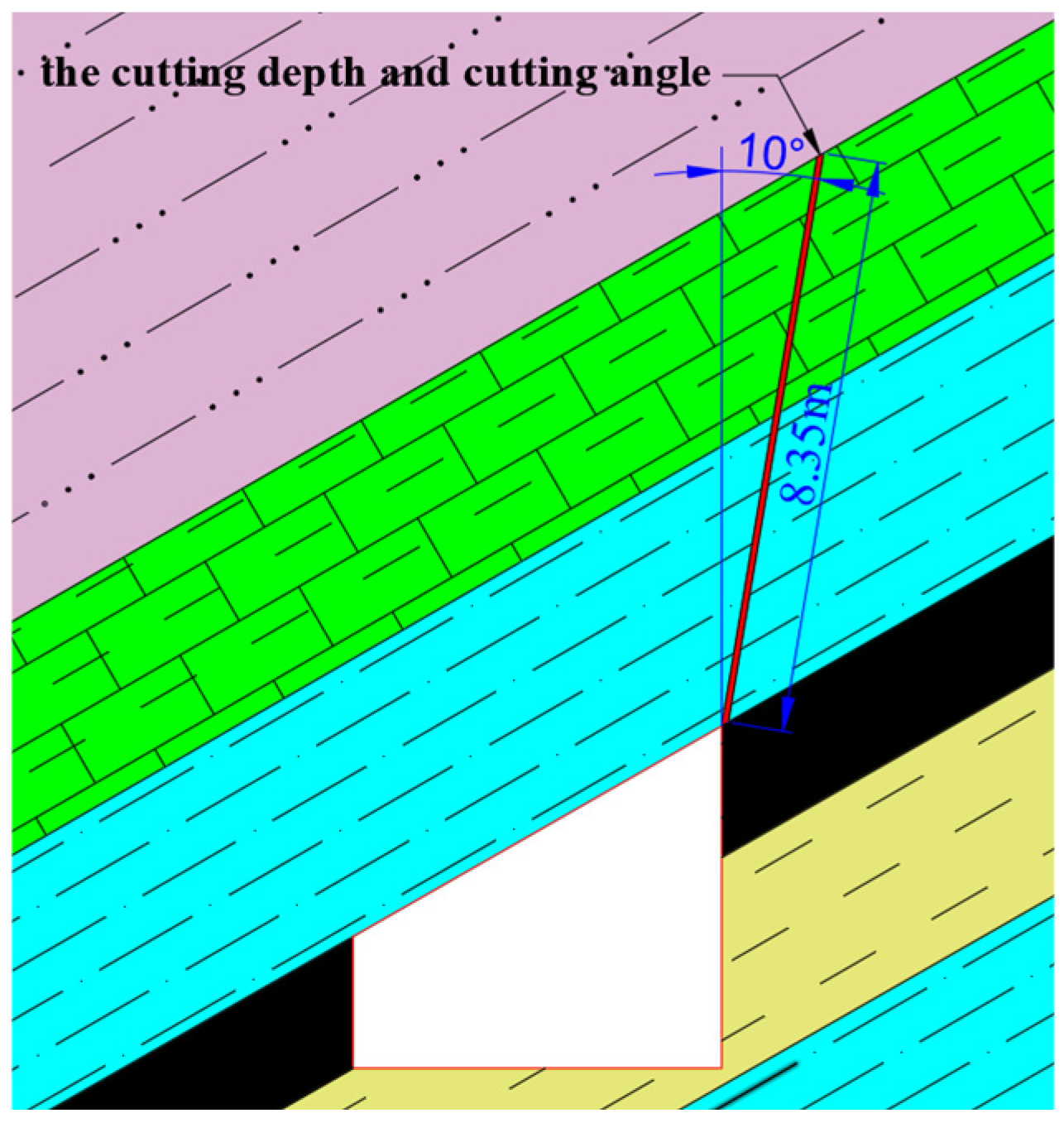
2.2. Engineering Parameters of Gob-Side Entry Retaining with Roof Cutting

(1)
Roof-cutting depth
To ensure that the roof on the goaf side can completely collapse along the pre-split cutting seam, it is necessary to set a reasonable roof-cutting depth [20].
In the formula, Hc represents the mining height, and K is the rock bulking coefficient, which generally ranges from 1.25 to 1.5.
Based on the on-site measurements at the 3131 working face, the mining height Hc = 1.7 m, and the rock bulking coefficient K = 1.3 m. Substituting these values into the above formula, the calculated cutting-seam depth should be at least 5.7 m. Considering the actual geological conditions, the roof-cutting depth needs to reach the argillaceous limestone layer of the main roof.
(2)
Roof-cutting angle
For the purpose of optimizing the cutting-off effect of the roof on the goaf side and reducing the frictional resistance between the cutting surfaces, the roof-cutting angle θ is required to satisfy the following condition [21]:
θ = φ arctan 2 h m Δ S L
Substitute the on-site data as follows: the internal friction angle of the rock block φ = 37°, the length of the roof rock block L = 18 m, the subsidence of the rock block ΔS = 1.7 m, and the thickness of the roof strata hm = 6.4 m into the above formula. The calculated result shows that θ ≥ 9.4°. For the convenience of on-site construction, the angle between the roof-cutting line and the vertical direction should be at least 10°.
(3)
Spacing between blasting boreholes
In the design process of blasting hole spacing, in order to ensure its rationality, it is necessary to determine the optimal blasting hole spacing based on the geological conditions of the site and the requirements of pre-splitting blasting technology [20]:
d 2 r b 1 + λ P b 1 D 0 σ t + p 1 δ
In the formula, d represents the distance between the centers of the blast holes; rb is the radius of the blast hole; λ is the lateral pressure coefficient, where λ = μ/(1 − μ), and μ is Poisson’s ratio; p is the in situ rock stress; Pb is the peak pressure of the shock wave on the blast-hole wall; D0 is the initial damage parameter of the rock mass; σt is the tensile strength of the rock; δ is the attenuation coefficient of the blasting stress wave, and δ = 2 − μ/(1 − μ).
Based on the diameter of the shaped charge tube, the diameter of the roof-cutting and pressure-relief blasting holes is determined to be 50 mm, that is, rb = 25 mm. Substitute μ = 0.22, p = 14 MPa, Pb = 1300 MPa, D0 = 0.55, and σt = 3.2 MPa into the above formula. The calculated result shows that d ≤ 735 mm. Considering the actual geological and engineering conditions of this working face, the final spacing of the roof-cutting and pressure-relief blasting holes is determined to be 500 mm.
In summary, as shown in Figure 2, the cutting depth and cutting angle are designed to be 8.35 m and 10°, respectively, and the blasting hole spacing is designed to be 500 mm.

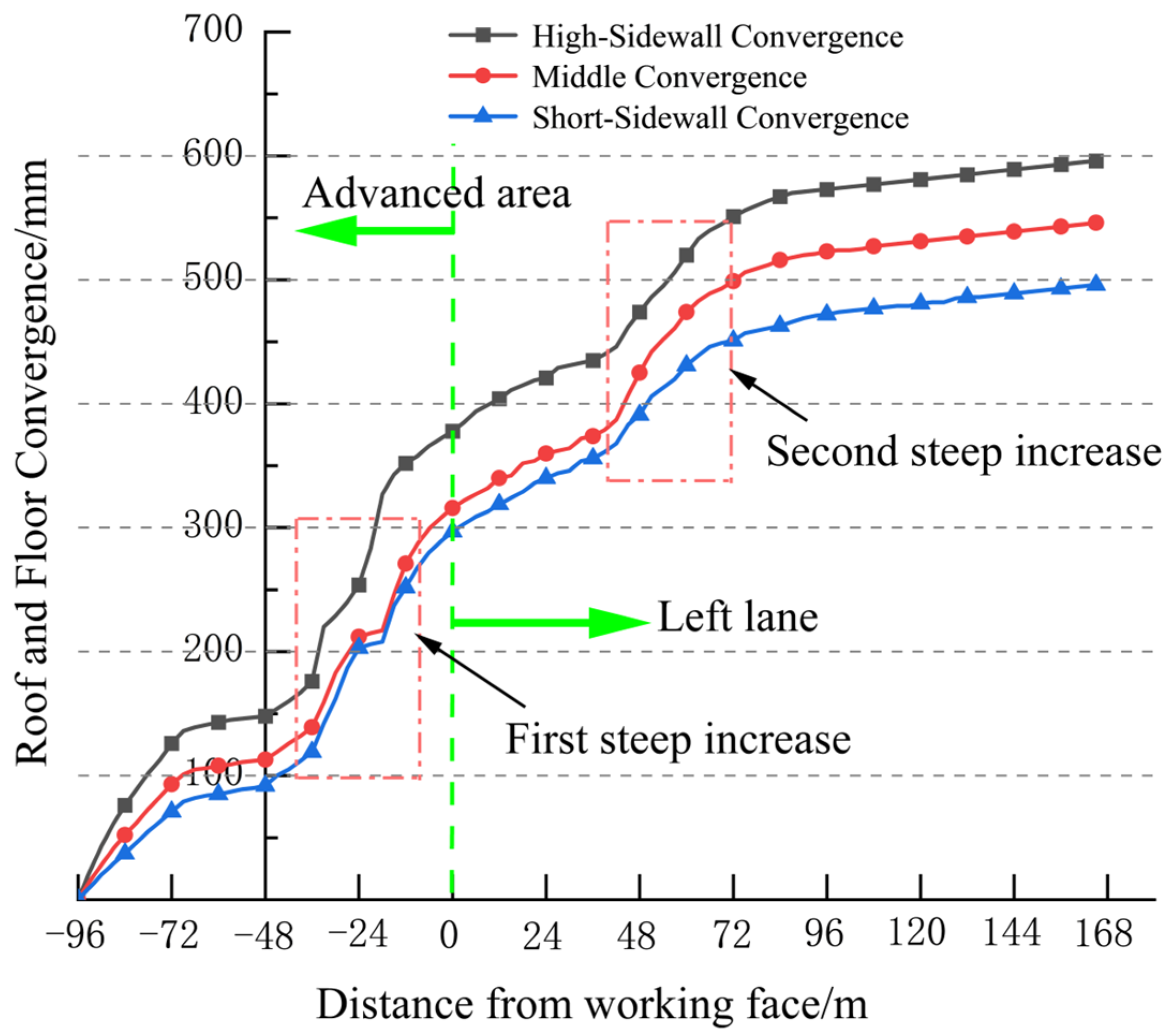
3. Deformation Characteristics of Surrounding Rock in 3131 Transport Roadway

In order to master the deformation and activity law of the surrounding rock in 3131 transport roadway during the driving period, primary mining period, and retaining period, surface displacement measuring stations were arranged at 30 m, 45 m, and 60 m from the open-off cut of 3131 working face in 3131 transport roadway. The curves of roof and floor convergence in different periods at 45 m from the open-off cut of 3131 working face are shown in Figure 3.
During these three periods, the roof-to-floor convergence showed a continuously increasing trend. The roof-to-floor convergence on the high side of the roadway was greater than that in the middle part of the roadway, and the roof-to-floor convergence in the middle part was greater than that on the low side of the roadway. Evidently, the surrounding rock exhibited non-uniform deformation characteristics. Meanwhile, during the first mining period and the roadway-retention period, the roof-to-floor convergence increased significantly and steeply.
The deformation and failure of the surrounding rock in the gob-side entry retaining with roof-cutting in the No. 3131 haulage roadway are related to the structural changes of the main roof and the support measures. Therefore, it is necessary to conduct an in-depth study on the mechanical state of the main roof.

4. Mechanical Analysis of Roof Structure of Gob-Side Entry Retaining with Roof Cutting

4.1. Analysis of Evolution Characteristics of Roof Structure

Following coal seam extraction in the working face, large-scale movement of overlying strata induces continuous stress redistribution, forming a mining-induced stress field. As the retained roadway is situated along the goaf edge, its roof becomes inevitably subjected to this stress field. After implementing advanced slotting pressure relief in the front roof of the working face, the overlying rock beams within the extraction space undergo dynamic evolution involving caving, accumulation, and compaction processes as mining progresses. Accordingly, the roof structure of the roadway demonstrates significant modifications. Building upon References [22,23], which classified horizontal roof-cut roadways into three zones based on roof-sidewall connectivity—working face advance zone (I), dynamic pressure zone of formed roadway (II), and stable pressure zone of formed roadway (III)—this study extends the classification to inclined roof-cut roadways and categorizing them into four distinct phases: roadway excavation period, primary mining advanced influence period, retained roadway period, and secondary mining advanced influence period.
Roadway excavation period: As shown in Figure 4a, the roof has not been cut in advance and is not affected by the mining work, and the roof structure has not changed significantly. Table 1 is the basic top structural mechanics hypothesis.
Advanced influence period of the first mining: As depicted in Figure 4b, after pre-splitting blasting is carried out on the roadway roof in front of the working face, the continuity between the roof of the working face and the roadway roof is disrupted. Most of the load originally acting on the rocks above the goaf gradually starts to transfer to the solid coal of the adjacent working face. This effectively reduces the pressure and potential risks exerted by the load on the roadway roof. Since the coal-mining working face is behind, the solid coal on the high side still supports the roadway roof. When the coal-mining work approaches the advanced cutting seam, due to the influence of advanced mining, the continuity between the roof of the working face and the roadway roof is basically severed. Table 2 is the basic top structural mechanics hypothesis.
Roadway-retaining period: After the advanced cutting-seam, as the coal-mining face advances, parts of the roof rocks collapse and roll down along the dip angle. The main roof gradually forms a hinged structure of rock block A and rock block B. Rock block B rotates and subsides towards the goaf side, gradually compressing the waste rocks until it finally stabilizes, as shown in Figure 4c. In contrast to horizontal gob-side entry retaining with roof cutting, the dip angle of strata induces gravitational sliding of rock block B, which exerts a compressive force FN on rock block A. Table 3 is the basic top structural mechanics hypothesis.
Advanced influence period of the second mining: Before the start of the second mining, the retained roadway roof has already experienced the impact of the first mining and formed a relatively stable structure. However, during the second mining, as the new working face advances, the advanced abutment pressure gradually increases, resulting in new subsidence and deformation of the roof. Nevertheless, the accumulated waste rocks provide a certain supporting force to the roof. The structural form of the surrounding rock is shown in Figure 4d. Table 4 is the basic top structural mechanics hypothesis.

4.2. Analysis on Mechanical State of Basic Roof of Gob-Side Entry Retaining with Roof Cutting

Compared with traditional roadway-retaining methods, after the advanced roof-cutting of the roadway, the structural form of the surrounding rock and the stress distribution of the roof change significantly. The roof beam changes from being fixed-supported at both ends to being fixed-supported at one end and simply-supported at the other end. At this point, the roof beam is in a statically indeterminate state. We assume that the length of the roof beam is l, the thickness of the roof is h, the angle between the roof beam and the horizontal is α, and the body force can be neglected.
The stress distribution and deflection of the roof can be deduced by using the semi-inverse method of elastic mechanics [24]. The compressive stress σy is mainly induced by the direct load q, and, since q does not vary with x, it can be assumed that σy is independent of x. In other words, σy is assumed to be a function of y only: σy = f (y). Substitute σy into the equilibrium differential equations to derive the full solution of the stress function:
ϕ = 1 2 x 2 f y + x f 1 y + f 2 y
Substituting it into the compatibility equation, the stress component can be obtained as follows:
σ x = 1 2 x 2 6 A 1 y + 2 A 2 + x 6 A 5 y + 2 A 6 2 A 1 y 3 2 A 2 y 2 + 6 A 8 y + 2 A 9 σ y = A 1 y 3 + A 2 y 2 + A 3 y + A 4 τ y x = x 3 A 1 y 2 + 2 A 2 y + A 3 3 A 5 y 2 + 2 A 6 y + A 7

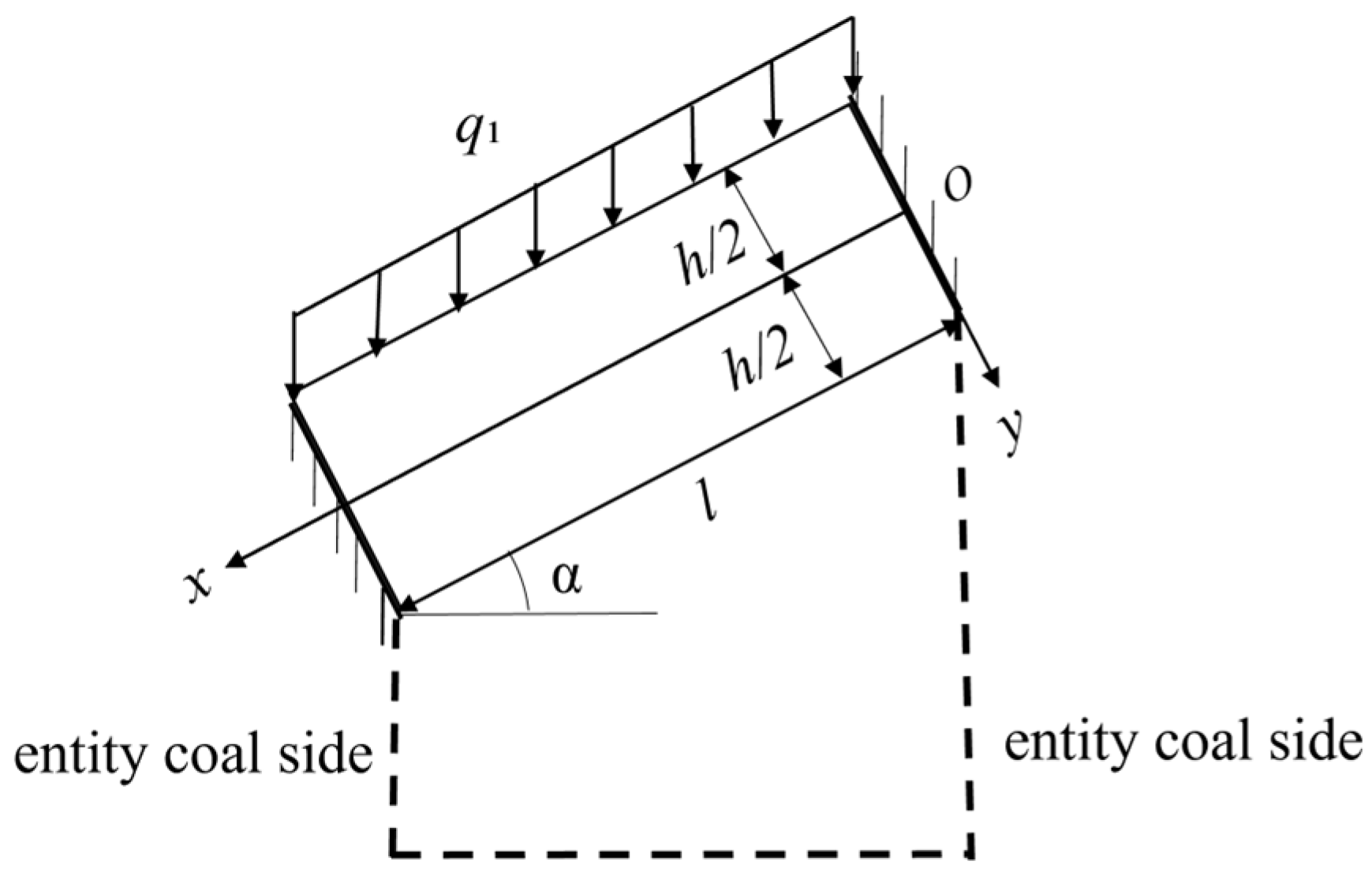
4.2.1. Analysis of Mechanical State of Basic Roof in Roadway Excavation Period

During the roadway development phase, the main roof can be conceptualized as a fixed-end beam structure, triple-statically indeterminate, anchored by intact coal ribs at both extremities The corresponding mechanical model is illustrated in Figure 5, where the uniformly distributed overburden load q1 is designated as 7100 KN/m.
The upper and lower boundaries of the beam constitute the majority of its total boundaries, thus representing the primary boundaries. On these primary boundaries, the stress boundary conditions must be strictly satisfied. For the small lateral boundaries (occupying a minor portion of the total boundaries), when boundary conditions cannot be strictly satisfied, Saint-Venant’s Principle may be invoked (hereinafter, the same applies).
According to the mechanical model, the primary boundary conditions for the upper and lower boundaries are as follows:
σ y y = h 2 = 0 , σ y y = h 2 = q 1 cos α τ y x y = h 2 = q 1 sin α , τ y x y = h 2 = 0
For the smallleft and right boundary conditions, the following is true:
u x = 0 , y = 0 = 0 , v x = 0 , y = 0 = 0 , v x x = 0 , y = 0 = 0 u x = l , y = 0 = 0 , v x = l , y = 0 = 0 , v x x = l , y = 0 = 0
Combined with geometric equations and physical equations, the stress component is solved:
σ x = q 1 cos α h 3 6 x 2 y + 6 l x y + 4 y 3 l 2 y + q 1 cos α 3 ( 2 + μ ) 2 h y μ 2 + q 1 sin α 1 h x + l 2 h σ y = q 1 cos α 2 h 3 y 3 + 3 2 h y 1 2 τ y x = q 1 cos α 6 h 3 x y 2 3 2 h x 3 l h 3 y 2 + 3 l 4 h + q 1 sin α 1 h y 1 2
The deflection equation is as follows:
v 1 y = 0 = q 1 cos α 2 E h 3 x 4 2 l x 3 + l 2 x 2
The deflection Equation (8) shows that the deflection is symmetrically distributed with the change of beam length, and its size is directly affected by the inclination angle and the thickness of the basic roof.
The relevant parameters of 3131 transport roadway are as follows: the thickness of basic roof rock beam h = 1.2 m, the length of beam l = 4.8 m, the dip angle of coal seam α = 30°, the elastic modulus E = 7.37 Gpa, and the Poisson‘s ratio μ = 0.22, which are substituted into the expression of stress and deflection (the same as below).
Of particular importance are the parametric requirements for the deflection equation, which must satisfy the following fundamental constraints:
The beam shall be a prismatic straight beam with uniform thickness, whose length-to-thickness ratio must satisfy the small deformation assumption of classical beam theory. The roof stratum is required to be a linearly elastic, isotropic, and homogeneous material, with the elastic modulus E and Poisson’s ratio μ maintained within their elastic ranges. The applied load q must constitute a uniformly distributed vertical load acting perpendicular to the horizontal plane (the same below).
The variation in the normal stress component is shown in Figure 6. Since the two ends of the main roof rock beam are fixed, the tensile stress concentration appears at both ends of the upper half of the rock beam, which is about three times that of the original rock stress, and the compressive stress concentration appears at both ends of the lower half of the rock beam, which is about 2.46 times that of the original rock stress.
The stress field exhibits symmetrical distribution characteristics, resulting in correspondingly symmetrical deflection, as depicted in Figure 7. Subjected to gravitational loading and roadway excavation effects, the main roof rock beam demonstrates a maximum subsidence of approximately 8.0 mm at its midspan region. The roadway maintains optimal stability due to the absence of additional engineering disturbances.

4.2.2. Analysis of Mechanical State of Main Roof in Advanced Influence Period of Primary Mining

During the advanced influence period of the first mining, the main roof can be regarded as a simply-supported beam structure, with one end fixed-supported by the solid coal of the next working face and the other end simply-supported on the solid coal of the current working face. This forms a first-degree statically indeterminate structure. The mechanical model of the main roof structure is shown in Figure 8. In the figure, q2 represents the uniformly distributed load of the overlying rock strata, and Fc represents the supporting force of the solid coal. Given that q2 = 4200 KN/m, and based on the law of action and reaction, Fc = q2 cosα = 3637 KN/m.
According to the mechanical model, the primary boundary conditions for the upper and lower boundaries are as follows:
σ y y = h 2 = 0     σ y y = h 2 = q 2 cos α τ y x y = h 2 = q 2 sin α     τ y x y = h 2 = 0
We use Saint-Venant’s Principle to obtain the left and right boundary conditions as follows:
h / 2 h / 2 ( σ x ) x = 0 d y = 0 h / 2 h / 2 ( σ x ) x = 0 y d y = 0 h / 2 h / 2 τ x y d y = F c
The stress expression is obtained as follows:
σ x = q 2 cos α 6 h 3 x 2 y + 4 h 3 y 3 3 5 h y + q 2 sin α 6 h 2 x y 1 h x + 12 F c h 3 x y σ y = q 2 cos α 2 h 3 y 3 + 3 2 h y 1 2 τ y x = q 2 cos α 6 h 3 x y 2 + 3 2 h x 6 F c h 3 y 2 + 3 F c 2 h + q 2 sin α 3 h 2 y 2 + 1 h y + 1 4
According to the displacement boundary conditions of the beam, the following is true:
u x = l , y = 0 = 0 , v x = l , y = 0 = 0 , v x x = l , y = 0 = 0
The geometric equations and physical equations are obtained, so that the deflection equation is as follows:
v 2 y = 0 = 1 E q 2 cos α 2 h 3 x 4 q 2 sin α h 2 x 3 3 ( μ + 2 ) q 2 cos α 4 h x 2 + q 2 cos α 2 l 3 h 3 + 3 ( μ + 2 ) l 2 h 3 l 5 h x + q 2 sin α 3 l 2 h 2 x 2 l 3 q 2 sin α h 2 + 3 q 2 cos α 10 h x 2 + q 2 cos α 3 l 4 2 h 3 3 ( μ + 2 ) l 2 4 h + 3 l 2 10 h 2 F c h 3 x 3 + 6 l 2 h 3 F c x 4 l 3 F c h 3
The variation in normal stress components is shown in Figure 9. In the upper part of the main roof, tensile stress is concentrated on the low side of the roadway, with the maximum tensile stress being approximately 3.2 times the in situ rock stress, while compressive stress exists on the high side. In the lower part of the main roof, compressive stress is concentrated on the low side of the roadway, with the maximum compressive stress being approximately four times that of the in situ rock stress, and tensile stress occurs on the high side.
As shown in Figure 10, the deflection profile under directional presplitting and stress distribution reveals exacerbated roof subsidence proximal to the high sidewall. The high-sidewall deflection reaches 42 mm, representing a 1.82-fold amplification compared to the mid-span deformation values.

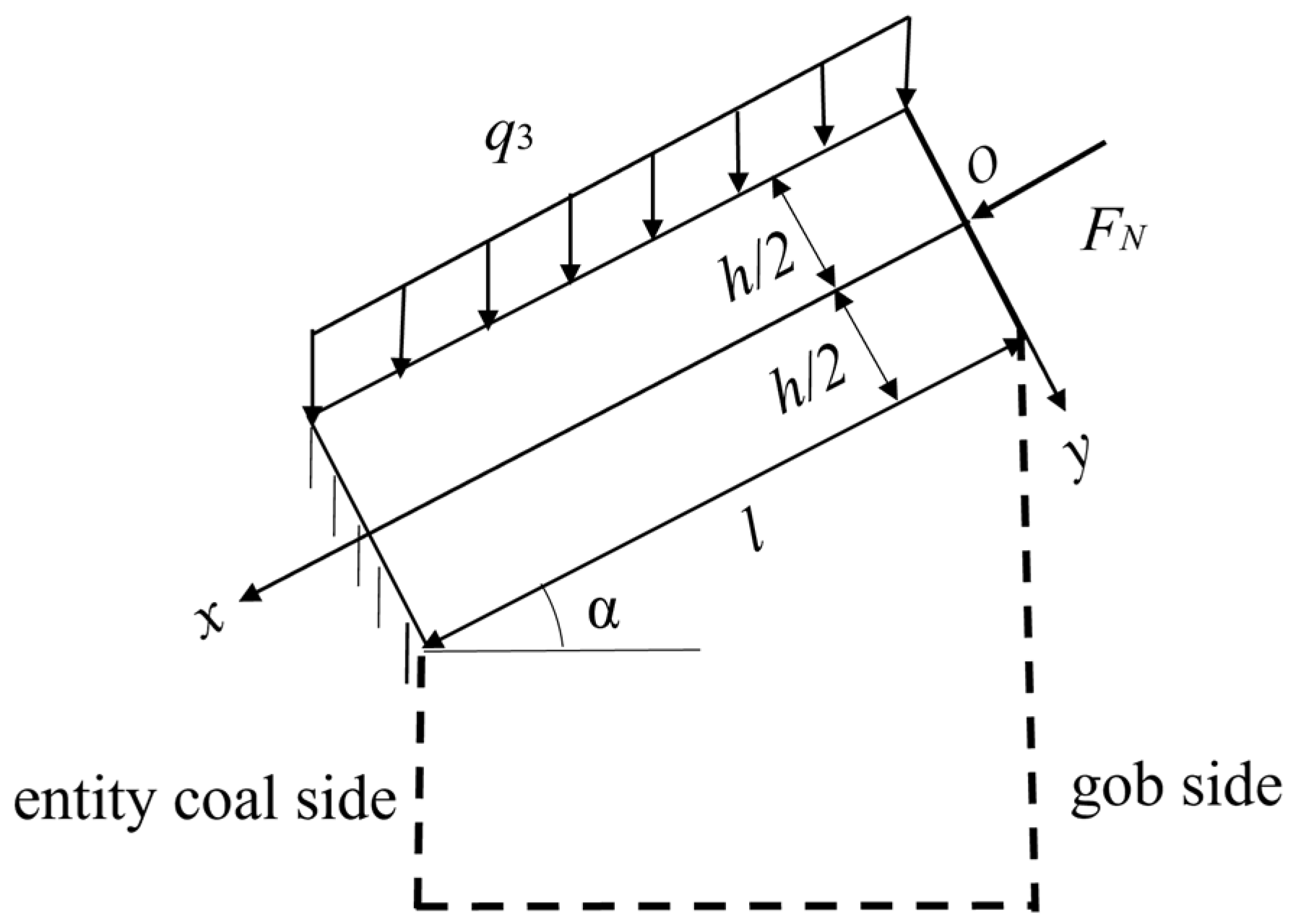
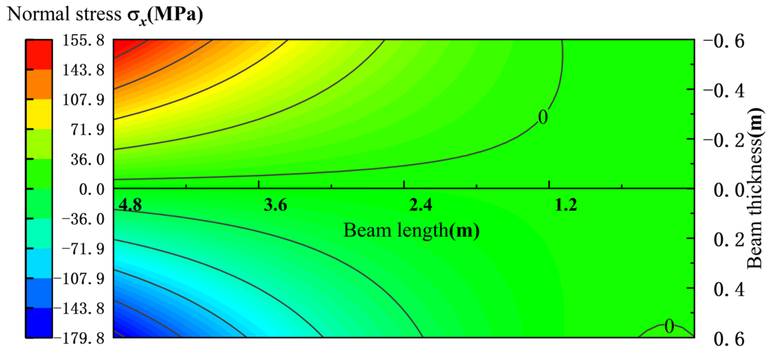
4.2.3. Analysis of Mechanical State of Basic Roof in Roadway Retaining Period

During the roadway-retaining period, the main roof can be regarded as a cantilever beam structure with one end fixed-supported on the solid coal and the other end exposed in the goaf. The mechanical model of the main roof structure is shown in Figure 11. In the figure, q3 represents the uniformly distributed load of the overlying rock strata, and q3 = 6800 KN/m. FN represents the lateral pressure of rock block B on rock block A. FN is taken as the self-weight component of rock block B along the x-axis, that is, FN = 1250 KN/m.
According to the mechanical model, the primary boundary conditions for the upper and lower boundaries are as follows:
σ y y = h 2 = 0     σ y y = h 2 = q 3 cos α τ y x y = h 2 = q 3 sin α     τ y x y = h 2 = 0
The left and right boundary conditions were established by applying Saint-Venant’s principle:
h / 2 h / 2 ( σ x ) x = 0 d y = F N h / 2 h / 2 ( σ x ) x = 0 y d y = 0 h / 2 h / 2 τ x y d y = 0
The stress expression is obtained as follows:
σ x = q 3 cos α 6 h 3 x 2 y + 4 h 3 y 3 3 5 h y + q 3 sin α 6 h 2 x y 1 h x F N h σ y = q 3 cos α 2 h 3 y 3 + 3 2 h y 1 2 τ y x = q 3 cos α 6 h 3 x y 2 + 3 2 h x + q 3 sin α 3 h 2 y 2 + 1 h y + 1 4
According to the displacement boundary conditions of the beam, the following is true:
u x = l , y = 0 = 0 , v x = l , y = 0 = 0 , v x x = l , y = 0 = 0
The geometric equations and physical equations show that the deflection equation is as follows:
v 3 y = 0 = 1 E q 3 cos α 2 h 3 x 4 q 3 sin α h 2 x 3 3 ( μ + 2 ) q 3 cos α 4 h x 2 + q 3 cos α 2 l 3 h 3 + 3 ( μ + 2 ) l 2 h 3 l 5 h x + 3 l 2 q 3 sin α h 2 x 2 l 3 q 3 sin α h 2 + 3 q 3 cos α 10 h x 2 + q 3 cos α 3 l 4 2 h 3 3 ( μ + 2 ) l 2 4 h + 3 l 2 10 h
The variation in normal stress components is shown in Figure 12. In the upper part of the main roof, tensile stress occurs in the middle and on the low side of the roadway, with tensile stress concentration at the sharp corners. The maximum tensile stress is approximately 7.79 times the in-situ rock stress, while the high side is under compressive stress. In the lower part of the main roof, compressive stress exists on the low side of the roadway, with compressive stress concentration at the sharp corners. The maximum compressive stress is approximately 8.99 times the in-situ rock stress, and the high side is hardly affected by tensile stress.
During the retained roadway period, the roof stress of the roadway increases compared to the primary mining advanced influence period, accompanied by a sharp rise in deflection. At the mid-section, the deflection reaches approximately 90.9 mm, representing an increase of about 67.9 mm relative to the primary mining advanced influence period. At the high-sidewall location, the deflection measures around 243.8 mm, with an increment of approximately 201.8 mm compared to the primary mining advanced influence period. The deflection variations are illustrated in Figure 13.

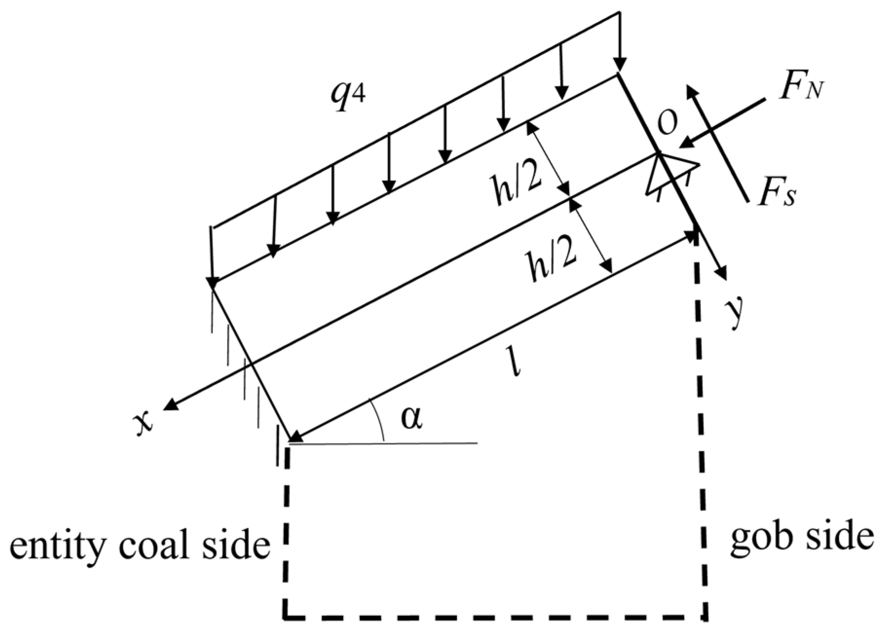
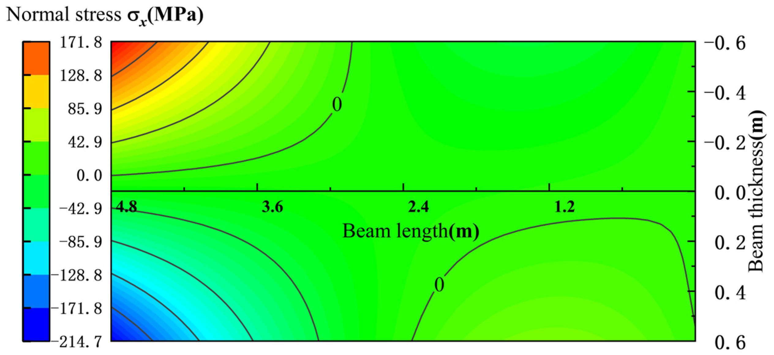
4.2.4. Analysis of Mechanical State of Main Roof in Advanced Influence Period of Secondary Mining

During the advanced influence period of the second mining, the main roof can be regarded as a simply-supported beam structure with one end fixed-supported by solid coal and the other end simply-supported by the goaf waste rocks. It is a first-degree statically indeterminate structure. The stress state of the roof structure is shown in Figure 14. In the figure, q4 represents the uniformly-distributed load of the overlying rock strata, and q4 = 10,100 KN/m. Fs represents the supporting force of the waste rocks, and FN represents the lateral pressure of rock block B on rock block A. FN is taken as the self-weight component of rock block B along the x-axis, that is, FN = 1250 KN/m.
According to the mechanical model, the primary boundary conditions for the upper and lower boundaries are as follows:
σ y y = h 2 = 0     σ y y = h 2 = q 4 cos α τ y x y = h 2 = q 4 sin α     τ y x y = h 2 = 0
We then use Saint-Venant’s Principle to obtain the left and right boundary conditions:
h / 2 h / 2 ( σ x ) x = 0 d y = F N h / 2 h / 2 ( σ x ) x = 0 y d y = 0 h / 2 h / 2 τ x y d y = F S
The stress expression is obtained as follows:
σ x = q 4 cos α 6 h 3 x 2 y + 4 h 3 y 3 3 5 h y + q 4 sin α 6 h 2 x y 1 h x F N h + 12 F S h 3 x y σ y = q 4 cos α 2 h 3 y 3 + 3 2 h y 1 2 τ y x = q 4 cos α 6 h 3 x y 2 + 3 2 h x + q 4 sin α 3 h 2 y 2 + 1 h y + 1 4 + 3 2 h 6 h 3 y 2 F S
According to the displacement boundary conditions of the beam, the following is true:
u x = l , y = 0 = 0 , v x = l , y = 0 = 0 , v x x = l , y = 0 = 0
The geometric equations and physical equations are such that the deflection equation is as follows:
v 4 y = 0 = 1 E q 4 cos α 2 h 3 x 4 q 4 sin α h 2 x 3 3 ( μ + 2 ) q 4 cos α 4 h x 2 + q 4 cos α 2 l 3 h 3 + 3 ( μ + 2 ) l 2 h 3 l 5 h x + 3 l 2 q 4 sin α h 2 x 2 l 3 q 4 sin α h 2 + 3 q 4 cos α 10 h x 2 + q 4 cos α 3 l 4 2 h 3 3 ( μ + 2 ) l 2 4 h + 3 l 2 10 h + 2 h 3 x 3 + 6 l 2 h 3 x 4 l 3 h 3 F S
The variation in normal stress components is presented in Figure 15. In the upper part of the main roof, the low side of the roadway is under tensile stress, with tensile stress concentration at the sharp corners. The maximum tensile stress is approximately 8.59 times the in-situ rock stress, while the high side is under compressive stress. In the lower part of the main roof, the low side of the roadway is under compressive stress, with compressive stress concentration at the sharp corners. The maximum compressive stress is approximately 10.7 times the in-situ rock stress, and the high side is hardly affected by tensile stress.
Subjected to secondary mining-induced disturbances, the overlying strata experienced intensified load transfer and substantial stress escalation, with corresponding deflection characteristics delineated in Figure 16. Compared to the retained roadway period, the roof deflection continues to increase, measuring approximately 118.9 mm at the mid-section (an increment of about 28 mm) and around 302.2 mm at the high-sidewall location (an increase of approximately 58.4 mm) relative to the retained roadway period.
In summary, during the roadway excavation period, the tensile stress concentration occurs in the upper half of the two sides of the main roof rock beam, while the compressive stress concentration occurs in the lower half. Meanwhile, among the four stress concentration areas, the stress concentration area in the upper half of the short-wall side is the smallest, and the stress concentration area in the lower half of the short-wall side is the largest.
During the process of the first mining-induced advanced influence period, the roadway retaining period and the second mining-induced advanced influence period, the tensile stress area in the upper half of the main roof rock beam first increases and then decreases, that is, the tensile stress area in the upper half of the main roof is the largest during the roadway retaining period; the tensile stress area in the lower half of the main roof rock beam first decreases and then increases, and the lower half of the main roof is hardly affected by tensile stress during the roadway retaining period.
The deflection of the main roof is the smallest during the roadway excavation period. From the first mining-induced advanced influence period, the roadway retaining period, to the second mining-induced advanced influence period, the most significant deflection growth appears on the high-wall side, while, on the relatively high-wall side, the deflection increase in the middle area is slight.

4.3. Design of Roadside Support Resistance

As analyzed in Section 4.2, the deflection intensifies at the beginning of the roadway-retaining period. Therefore, roadside support is required to bear the pressure transmitted from the roof so as to maintain the stability of the roadway. Then, the deflection during the roadway-retaining period can be expressed as follows:
v 3 y = 0 = 1 E q 3 cos α 2 h 3 x 4 q 3 sin α h 2 x 3 3 ( μ + 2 ) q 3 cos α 4 h x 2 + 3 q 3 cos α 10 h x 2 + q 3 cos α 2 l 3 h 3 + 3 ( μ + 2 ) l 2 h 3 l 5 h x + 3 l 2 q 3 sin α h 2 x 2 l 3 q 3 sin α h 2 + q 3 cos α 3 l 4 2 h 3 3 ( μ + 2 ) l 2 4 h + 3 l 2 10 h + 2 h 3 x 3 + 6 l 2 h 3 x 4 l 3 h 3 F S
Based on the deflection distribution described earlier, it is known that the deflection on the high-sidewall side is largest during the roadway-retaining period. After the roadside support is carried out during the roadway-retaining period, the most ideal roadway-retaining should ensure that the roof deformation no longer increases significantly. Therefore, it is assumed that the deflection at the point (0,0) on the high-sidewall side during roadway-retaining is the same as that during the first mining, that is, v2(0,0) = v3(0,0). Then, the relationship of the roadside support resistance, Equation (25), can be derived.
F s = q 3 cos α 3 l 8 3 ( μ + 2 ) h 2 16 l + 3 h 2 40 l h q 3 sin α 2 h 3 E v 2 4 l 3
The deflection change of the main roof with roadside support is shown in Figure 17. As can be seen from Figure 17, the deflection is approximately 49.1 mm, which is 194.8 mm lower than that without roadside support. This indicates that the control effect of the main roof is remarkable when roadside support is applied.
Based on Equation (24), the relationship between roadside support resistance and coal seam dip angle can be derived as shown in Figure 18 when beam length, rock beam thickness, and load remain constant. When the coal seam dip angle increases, the load component of the overlying load on the main roof along the direction perpendicular to the main roof decreases, thereby resulting in a decrease in the roadside support resistance.
Figure 18 provides a direct theoretical basis for the directional roof cutting and retained roadway support design in inclined coal seams. The dip angle-support resistance analysis enables cost-effective, high-safety, and self-adaptive support solutions. Successful field application in the No. 3131 roadway validates the engineering feasibility of this methodology, establishing a replicable design paradigm for mines under analogous geological conditions.

5. The Influence of Coal Seam Dip Angle on the Stability of Main Roof Rock Beam of Gob-Side Entry Retaining in Inclined Coal Seam

5.1. Influence of Dip Angle of Coal Seam on Stress State of Main Roof

Through the normal stress distribution map of each stage in Section 4.2, it is found that the stress distribution on the upper and lower sides of the main roof rock beam is complex, and the upper and lower sides of the main roof rock beam can represent the distribution of stress. Therefore, the influence of inclination angle on normal stress is analyzed for y = −h/2 and y = h/2, and the change of normal stress with inclination angle is shown in Figure 19.
During the roadway excavation period, in horizontal coal seams, the upper surface of the main roof exhibits tensile stress distribution at the low-wall side and high-wall side, while compressive stress dominates in the central region. Conversely, the lower surface demonstrates an inverse stress pattern. The overall stress distribution on the rock beam maintains symmetry under these conditions. However, when the coal seam contains a dip angle, this symmetry is disrupted, revealing pronounced asymmetric characteristics. Specifically, the maximum compressive stress in the central region of the upper surface shifts toward the low-wall side, whereas the maximum tensile stress in the central region of the lower surface migrates toward the high-wall side.
The advanced influence period of primary mining: near to the horizontal coal seam, the upper surface of the main roof rock beam is mainly subjected to tensile stress, and the lower surface is mainly subjected to compressive stress; as the dip angle of the coal seam increases, the area of the compressive stress on the upper surface gradually shifts from the high side to the low side, the area of the tensile stress decreases, and the lower surface is opposite to the upper surface.
Retaining period: The upper surface is generally in a state of tensile stress, while the lower surface is in a state of compressive stress. From the high side to the middle, the stress growth trend of the upper and lower surfaces is relatively flat. However, when moving from the middle to the low side, the stress value begins to rise sharply, forming a significant stress surge phenomenon.
The second mining advanced influence period: The stress state is similar to that of the first mining advanced influence period. The difference is that the stress value is significantly higher than that of the first mining advanced influence period and the retaining period.

5.2. Influence of Dip Angle of Coal Seam on Deflection Change of Main Roof

Substitute the relevant parameters of the 3131 working-face haulage roadway in Longmenxia South Coal Mine into Equations (8), (13), (18) and (23), and set the coal-seam dip angle α as a variable. Then, analyze the changing relationship between the main-roof deflection and the coal-seam dip angle.
As can be seen from Figure 20, when the length of the main roof beam is constant, the roof deflection of the (nearly) horizontal coal seams is the largest. As the dip angle of the coal seam increases, the component load perpendicular to the roof direction decreases, and the roof deflection decreases accordingly. Moreover, during the advanced influence period of the first mining activity, when the dip angle increases to 45 degrees, the maximum deflection value shifts from the high-rib side to the middle.
Integrated analysis of Figure 19 and Figure 20 demonstrates that increasing coal seam dip angles induce significant reductions in both maximum stress and deflection peaks across all operational stages. When the dip angle rises from 0° to 45°, the roadway excavation stage exhibits 13.6% stress peak reduction with a corresponding 29.6% deflection decrease. The primary mining advanced influence period shows 13.7% stress decline coupled with 90% deflection reduction. During the retained roadway phase, stress diminishes by 53.2% while deflection decreases by 54.2%, whereas the secondary mining advanced influence period achieves a 68.9% stress reduction and a 65.9% deflection mitigation. As summarized in Table 5, these systematic variations demonstrate distinct dip angle-dependent characteristics.

6. Engineering Practice

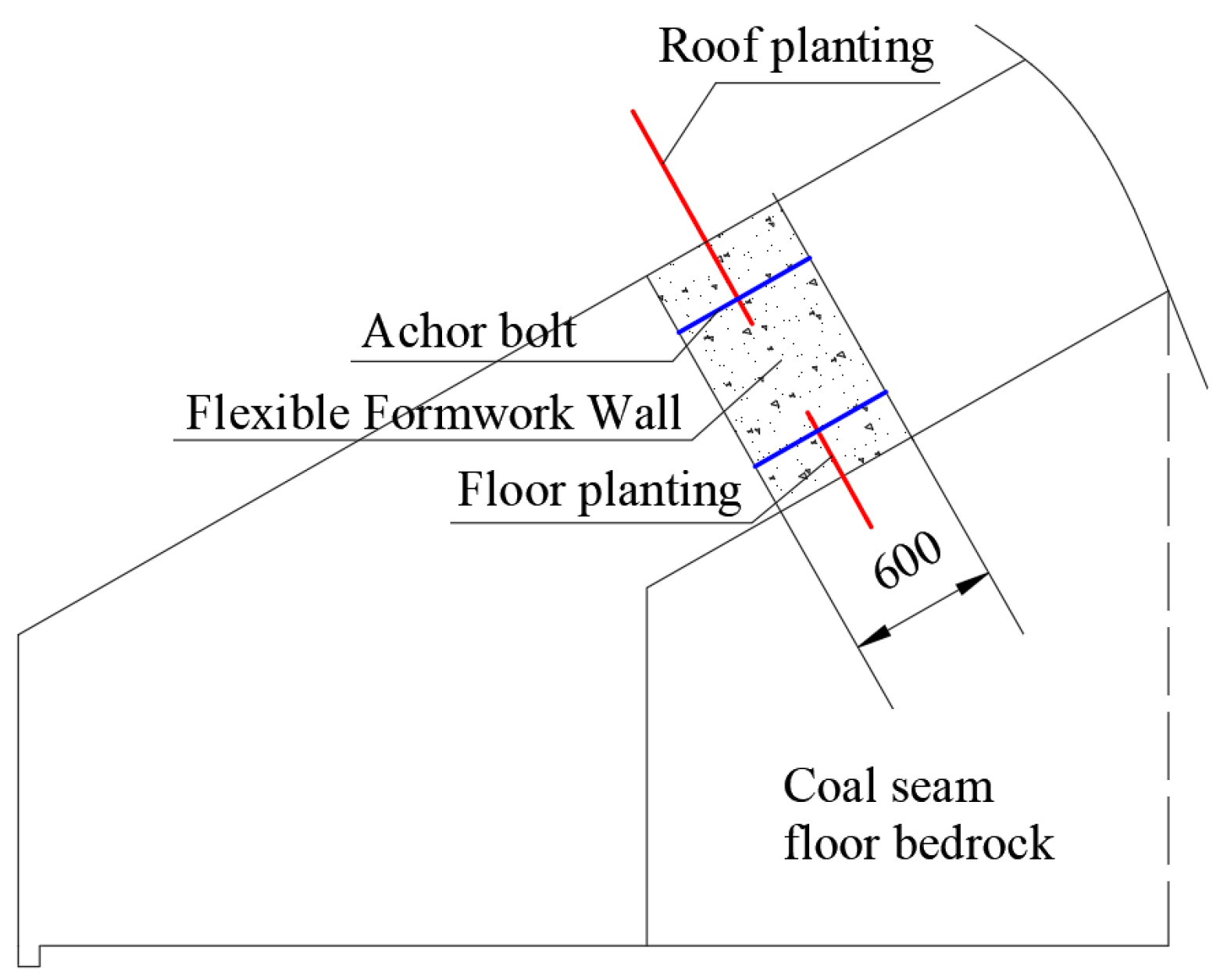
6.1. Design of Roadside Support for the No. 3131 Haulage Roadway

Based on the on-site geological conditions of the 3131 working-face haulage roadway in Longmenxia South Mine, it is designed to use stone powder cement slurry as the basic raw material for the flexible-formwork concrete wall. According to Equation (25), the calculated roadside support resistance for the No. 3131 haulage roadway is 5810 KN/m.
F s = q 3 cos α 3 l 8 3 ( μ + 2 ) h 2 16 l + 3 h 2 40 l h q 3 sin α 2 h 3 E v 2 4 l 3 = 6800 × cos 30 × 3 × 4.8 8 3 × ( 0.22 + 2 ) × 1.2 2 16 × 4.8 + 3 × 1.2 2 40 × 4.8 1.2 × 6800 × sin 30 2 1.2 3 × 7.37 × 10 6 × 0.2438 4 × 4.8 3 = 5810   KN / m
Based on the roadside support resistance, the designed strength of the wall is C20. Through experiments with different ratios of the basic raw materials, the concrete strength under each ratio was analyzed. Under the condition of meeting the strength requirements and considering economic rationality, it was determined that a ratio of stone powder to cement of 5:5 should be adopted for roadside filling. The underground construction effect of the roadside filling wall is shown in Figure 21.
The width of the designed roadside filling body is 0.6 m, and the height is 2 m. In order to enhance the anti-sliding and anti-overturning capabilities of the concrete wall and to restrain the lateral deformation of the concrete, reinforcement bars are planted at the top and bottom of the wall. The specific support scheme is shown in Figure 22.

6.2. On-Site Deformation Monitoring of Surrounding Rock

Through the field monitoring studies in Section 3, the deformation characteristics of the surrounding rock in the No. 3131 haulage roadway under non-backfilled roadside conditions were clarified for the roadway excavation period, primary mining period, and retained roadway period. The monitoring data revealed a maximum roof-to-floor deformation of 600 mm during the retained roadway period under these conditions. Combined with the theoretical calculations in Section 4.2.3 and Section 4.2.4, the basic roof deformation magnitudes during the retained roadway period and secondary mining advanced influence period were determined as 243.8 mm and 302.3 mm, respectively. Based on these findings, this study specifically designed roadside support resistance parameters, which were successfully implemented in engineering practice.
In order to verify the stability of the surrounding rock of the roadway after roadside filling support, monitoring stations are arranged in the No. 3131 haulage roadway to monitor the deformation of the high-sidewall side of the roadway. The monitoring results show that (1) behind the 3131 working face, the deformation of the surrounding rock tends to increase with the increase in the distance from the working face. When the distance from the 3131 working face is 35 m behind, the deformation of the roadway roof and floor reaches the maximum, that is, the maximum deformation of the roof and floor during the roadway-retaining period is about 165 mm. (2) With the continuous advancement of the 3112 working face, the deformation of the surrounding rock of the roadway near the 3112 working face is relatively large, and the maximum deformation of the roadway roof and floor is about 193 mm. At a relatively large distance from the 3112 working face, the maximum deformation of the roof and floor still remains at the level of the roadway-retaining period. The displacement of the surrounding rock of the roadway in each stage is within the allowable range, and the roadway-retaining effect is good. The monitoring results of the displacement of the roof and floor on the high-sidewall side of the No. 3131 haulage roadway are shown in Figure 23.
It is crucial to emphasize that the design methodology and parameters proposed in this study are derived from the specific geological conditions of the 3131 transport roadway in South Longmenxia Coal Mine, including an average burial depth of 400 m and a coal seam dip angle of 30°. Their practical application must be adaptively adjusted through comprehensive consideration of site-specific factors, including the physicomechanical properties of the coal and rock masses, mining-induced stress environment, and construction constraints.

7. Conclusions

(1)
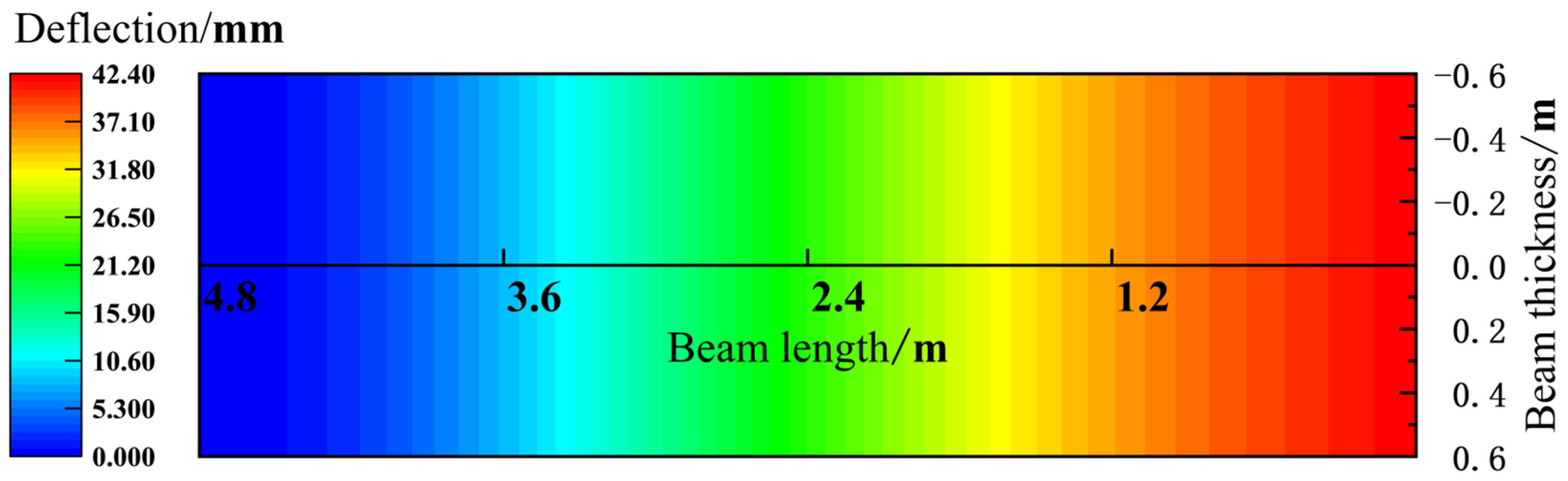
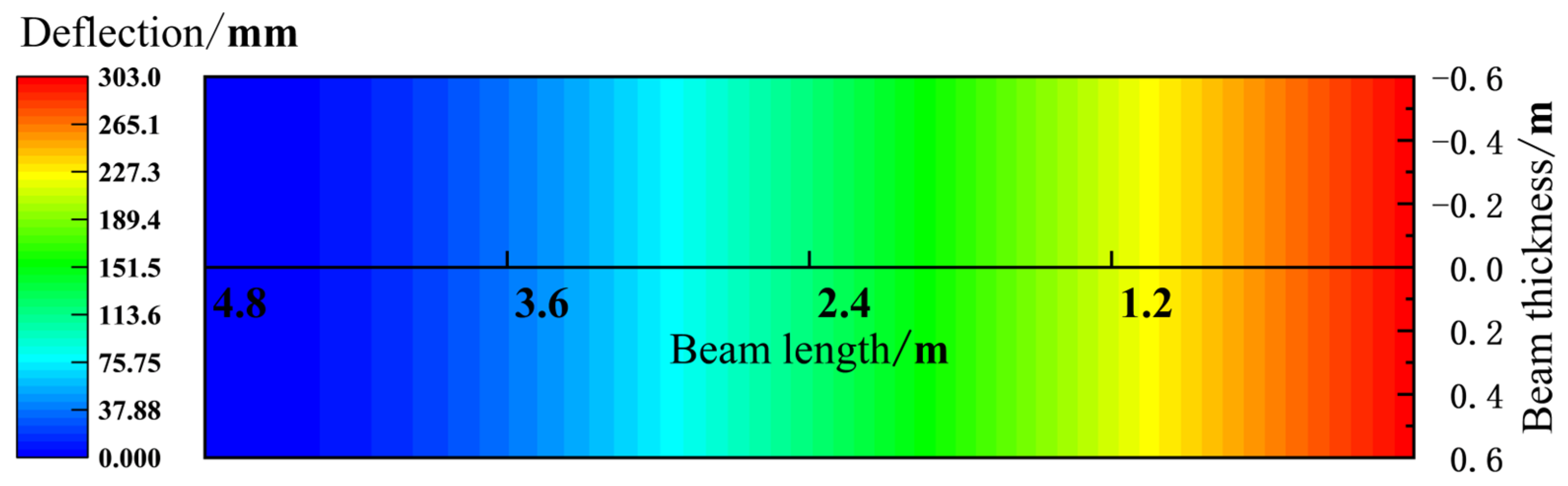
In the case where there is no roadside support in the No. 3131 haulage roadway, the main roof deflection is the smallest during the roadway excavation period. From the advanced influence period of the first mining activity, the roadway retaining period to the advanced influence period of the second mining activity, the deflection on the high-sidewall side shows the most significant growth, while the degree of deflection increase in the central area is relatively slight.
(2)
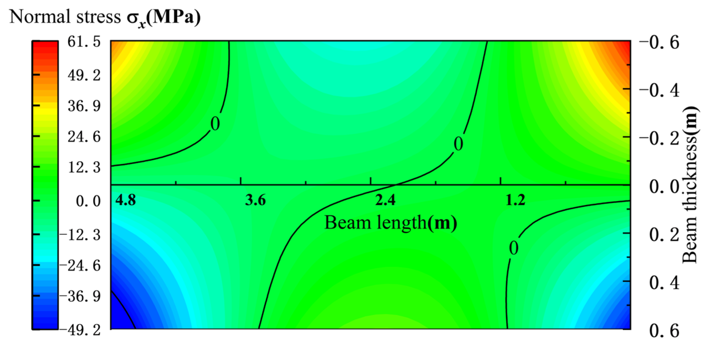
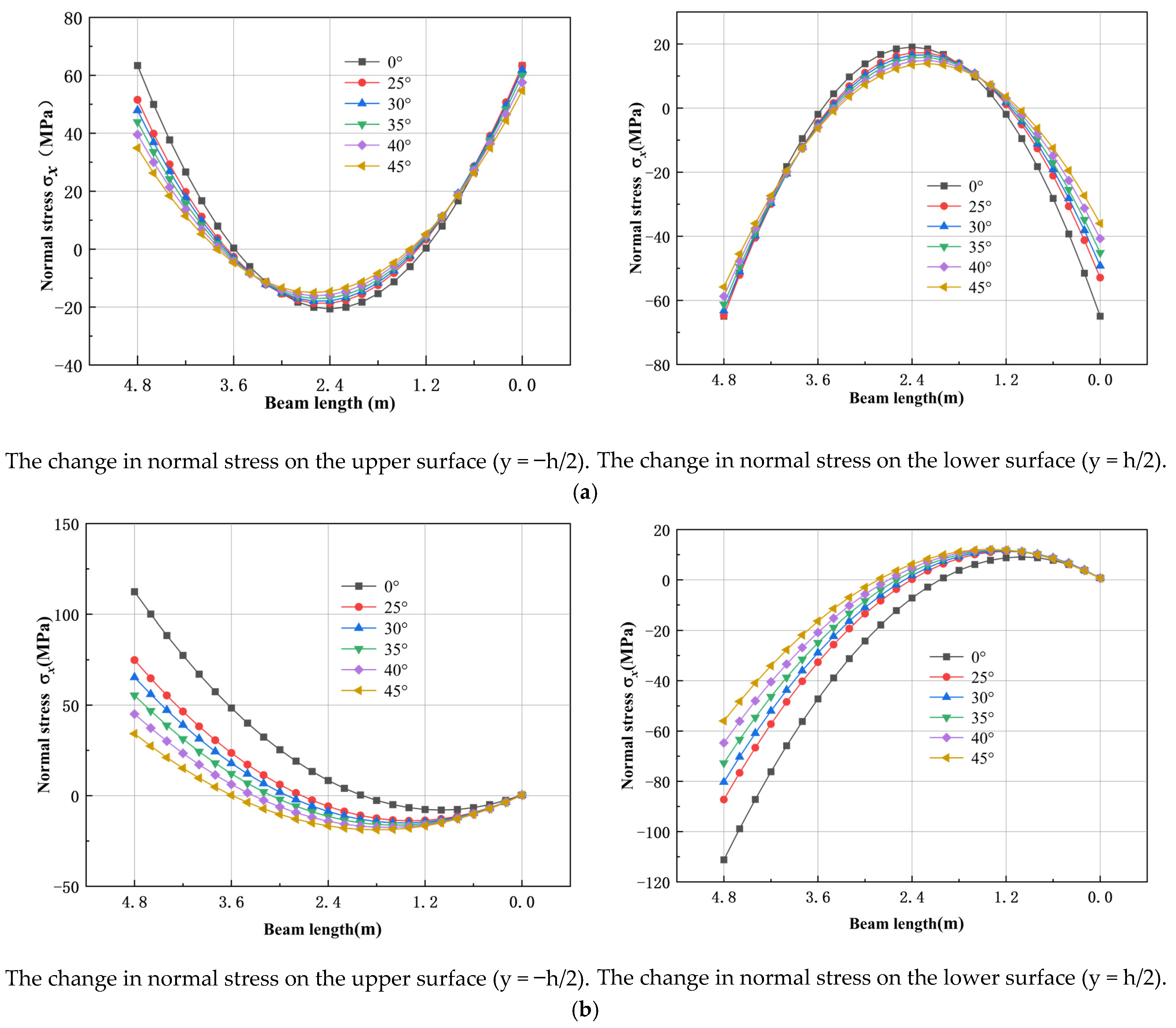
During the roadway excavation period, the normal stress σx of the main roof under the (nearly) horizontal coal seam shows a symmetrical distribution. As the coal seam dip angle increases, the maximum compressive stress in the middle of the upper surface shifts to the short-sidewall side, the maximum tensile stress in the middle of the lower surface shifts to the high-sidewall side, and the stress on the short-sidewall side decreases.
(3)
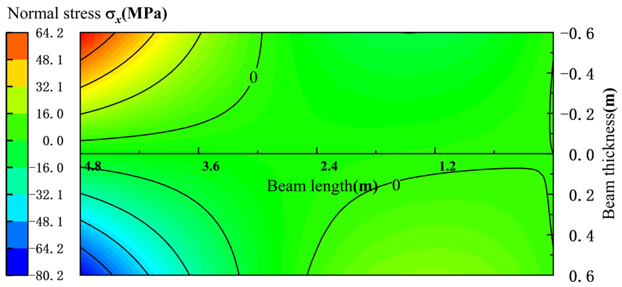
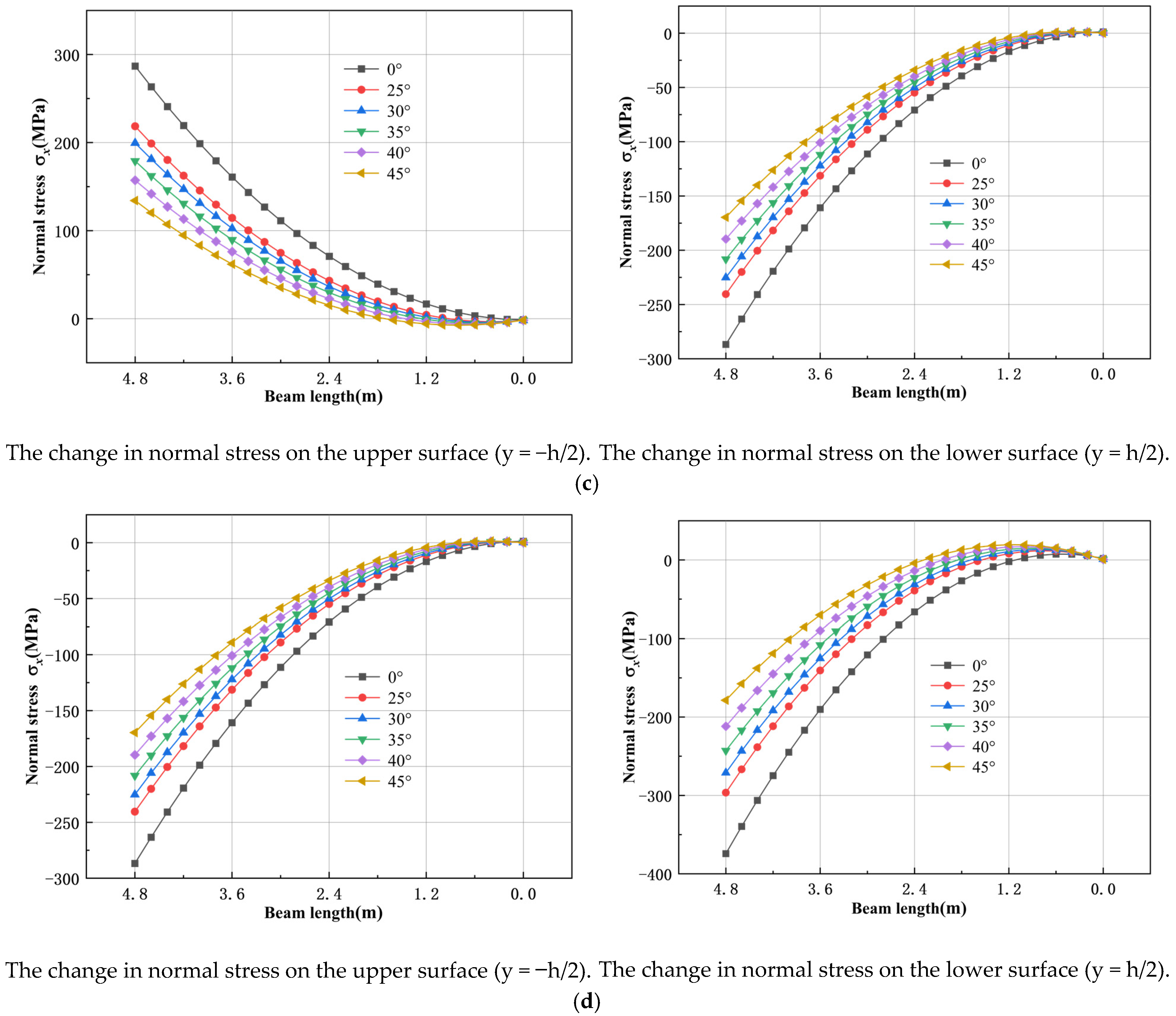
During the advanced influence period of the first mining activity and the advanced influence period of the second mining activity, the increase in the coal seam dip angle causes the compressive stress area on the upper surface of the main roof to expand from the high-sidewall side to the short-sidewall side, and the tensile stress area to decrease. The situation on the lower surface is the opposite, but the stress value is larger during the advanced influence period of the second mining activity.
(4)
During the roadway retaining period, the upper surface of the main roof is in tension, and the lower surface is under compression. The stress value increases slowly from the high-sidewall side to the middle, but sharply from the middle to the short-sidewall side.
(5)
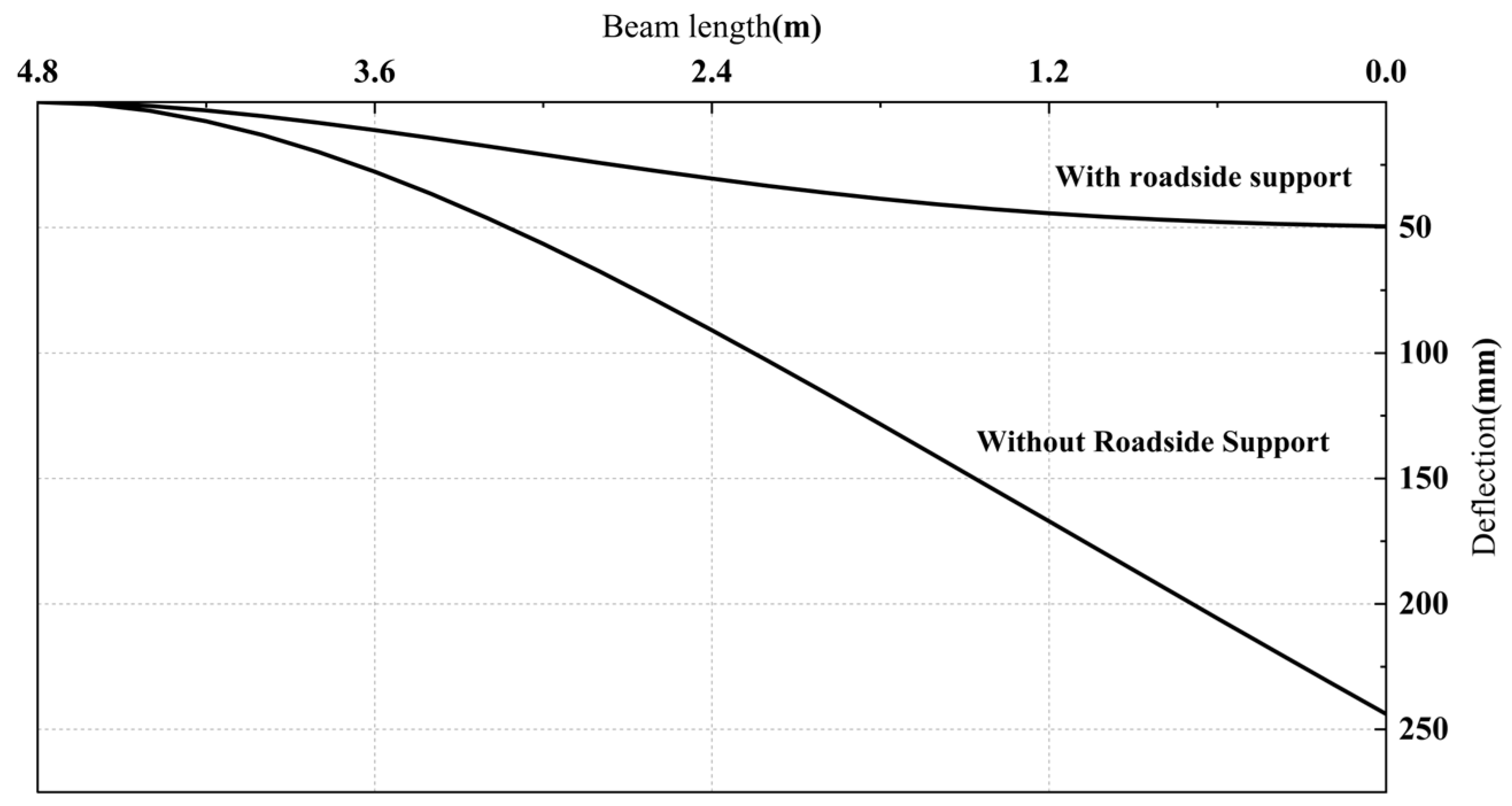
Under the inclined coal seam, as the dip angle of the coal and rock strata increases, the load component perpendicular to the main roof direction decreases, resulting in a decrease in the roof deflection and the roadside support resistance. The roadside backfill walls can be engineered based on the computational formulas for roadside support resistance, with specific design parameters calibrated according to in situ geological and operational conditions.

Author Contributions

Conceptualization, J.L., B.Y. and X.Q.; methodology, B.Y.; software, B.Y. and X.Q.; validation, B.Y.; formal analysis, B.Y. and X.Q.; resources, C.C., G.Z. and Y.Z.; data curation, B.Y. and J.D.; writing—original draft preparation, B.Y.; writing—review and editing, J.L. and X.Q.; visualization, B.Y., C.C., G.Z. and Y.Z.; supervision, J.L.; project administration, J.L. and J.D.; funding acquisition, J.L. All authors have read and agreed to the published version of the manuscript.

Funding

This research received no external funding.

Data Availability Statement

The raw data supporting the conclusions of this article will be made available by the authors on request.

Conflicts of Interest

Authors J.D., C.C., G.Z. and Y.Z. were employed by the Sichuan Xuyong No.1 Coal Mine Co., Ltd. The remaining authors declare that the research was conducted in the absence of any commercial or financial relationships that could be construed as a potential conflict of interest.

References

  1. Wang, X.; Wang, M.; Liu, J. Management of national planned coal mining areas and discrimination with coal mining areas. Coal Geol. Explor. 2019, 47, 219–222. [Google Scholar]
  2. Han, K.; Wang, Y. Developing trend and expectation of energy consume in China. J. China Univ. Min. Technol. 2004, 4–8. [Google Scholar] [CrossRef]
  3. Sun, H.; Zhao, B. Theory and Practice of Gob-Side Entry Retaining; Coal Industry Press: Beijing, China, 1993. [Google Scholar]
  4. Hua, X.; Li, C.; Liu, X.; Guo, Y.; Qi, Y.; Chen, D. Current situation of gob-side entry retaining and suggestions for its improvement in China. Coal Sci. Technol. 2023, 51, 128–145. [Google Scholar] [CrossRef]
  5. Yu, G.; Wang, J.; Ren, J.; Hu, J.; Pan, Z.; Wang, D.; Ming, W. Study on Surrounding Rock Structure Evolution Characteristics and Roof Control Techniques of the Retained Roadway Formed by Roof Cutting in Inclined Coal Seams. Shock Vib. 2021, 2021, 7491887. [Google Scholar] [CrossRef]
  6. Zhen, E.; Gao, Y. Application of Roof-Cutting and Pressure-Release Entry Retaining in Inclined Coal Seams: A Case Study. Geotech. Geol. Eng. 2020, 38, 2559–2572. [Google Scholar] [CrossRef]
  7. Zhang, L.; Zhao, J.; Zang, C.; Wang, S. An Innovative Approach for Gob-Side Entry Retaining by Roof Cutting in Steeply Pitching Seam Longwall Mining with Hard Roof: A Case Study. Min. Metall. Explor. 2020, 37, 1079–1091. [Google Scholar] [CrossRef]
  8. Wang, H.; Zhang, P.; Wang, M. Numerical study on the stability of surrounding rock of gob-side entry retaining along the fully mechanized working face in inclined seam. China Sci. Pap. 2015, 10, 2568–2573. [Google Scholar]
  9. Shi, W.; Li, Z.; Liu, C.; Lv, Y.; Zhang, H.; Yang, T. Study on optimization of key parameters of thick hard roof cutting and retaining roadway in inclined coal seam. Coal Sci. Technol. 2024, 52, 11–24. [Google Scholar]
  10. Zhu, Y.; Ren, H.; Wang, P.; Li, P.; Wang, X.; Wei, M. Stability control of gob-side entry retention under the condition of inclined thick layer and hard roof. J. Cent. South Univ. Sci. Technol. 2023, 54, 956–966. [Google Scholar]
  11. Cao, S.; Wang, Y.; Zou, D. Mechanical model analysis of roadway along the roadway in inclined coal seam. J. Chongqing Univ. Nat. Sci. Ed. 2013, 36, 143–150. [Google Scholar]
  12. Zhang, L.; Zhao, J.; Wang, S. Research on the roof structure evolution and control technology of gob-side entry retaining with cutting the roof in steeply dipping seam. J. Min. Sci. Technol. 2020, 5, 169–178. [Google Scholar] [CrossRef]
  13. Yang, J.; Fu, Q.; Gao, Y.; Cheng, Y.; Zhang, J. Research on roof deformation laws and mechanism in a non-pillar mining method with entry automatically formed during the whole cycle. J. China Coal Soc. 2020, 45, 87–98. [Google Scholar] [CrossRef]
  14. Yang, J.; Wei, Q.; Wang, Y.; Gao, Y.; Hou, S.; Qiao, B. Roof deformation mechanism and control measures of pillarless mining with gob-side entry retaining by roof cutting and pressure relief. Rock Soil Mech. 2020, 41, 989–998. [Google Scholar] [CrossRef]
  15. Yang, H.; Li, Y.; Liu, Y.; Cao, S.; Pan, R.; Wang, H.; Wang, B.; Chen, X.; Zhao, X. Structure evolution and stability control mechanism of hard-roof cutting for roadway retaining. J. Min. Saf. Eng. 2021, 38, 766–773. [Google Scholar] [CrossRef]
  16. Zhu, Z.; Zhang, K.; Yuan, H. Control Technology and Its Application of Roadway Side Wall Formed by Gangue in Gob-Side Entry Retaining Formed by Roof Cutting and Pressure Releasing. Coal Sci. Technol. 2018, 46, 25–32. [Google Scholar] [CrossRef]
  17. Zhu, Z.; Yuan, H.; Zhang, K.; Gao, Y. Analysis and control technology of roof subsidence in non-pillar gob-side entry retaining formed by roof cutting and pressure release. Coal Sci. Technol. 2018, 46, 1–7. [Google Scholar] [CrossRef]
  18. Liu, X.; Hua, X.; Yang, P.; Huang, Z. A Study of the Mechanical Structure of the Direct Roof during the Whole Process of Non-Pillar Gob-Side Entry Retaining by Roof Cutting. Energy Explor. Exploit. 2020, 38, 1706–1724. [Google Scholar] [CrossRef]
  19. Hu, J.; Ma, Z.; Guo, P.; Hu, Y. Fracture Evolution of the Main Roof in Gob-Side Entry Retaining by Roof Cutting of an Inclined Coal Seam. Energy Explor. Exploit. 2023, 41, 1396–1414. [Google Scholar] [CrossRef]
  20. He, M.; Ma, Z.; Guo, Z.; Chen, S. Key parameters of the gob-side entry retaining formed by roof cutting and pressure release in deep medium-thickness coal seams. J. China Univ. Min. Technol. 2018, 47, 468–477. [Google Scholar] [CrossRef]
  21. Chen, S.; Zhao, F.; Wang, H.; Yuan, G.; Guo, Z.; Yang, J. Determination of key parameters of gob-side entry retaining by cutting roof and its application to a deep mine. Rock Soil Mech. 2019, 40, 332–342+350. [Google Scholar] [CrossRef]
  22. Gao, Y.; Guo, Z.; Yang, J.; Wang, J.; Wang, Y. Steady analysis of gob-side entry retaining formed by roof fracturing and control techniques by optimizing mine pressure. J. China Coal Soc. 2017, 42, 1672–1681. [Google Scholar] [CrossRef]
  23. Huo, X. Evolution Characteristics of Surrounding Rock Deformation and Its Control Technology of Gob-Side Entry Retaining by Roof; Shandong University of Science and Technology: Qingdao, China, 2021. [Google Scholar]
  24. Xu, Z. A Concise Course in Elasticity; Higher Education Press: Beijing, China, 2018; ISBN 978-7-04-049871-4. [Google Scholar]
Figure 1. Comprehensive geological columnar section of the coal seam.
Symmetry 17 00723 g001
Figure 2. Cut top schematic diagram.
Symmetry 17 00723 g002
Figure 3. Curve of roof−to−floor convergence of 3131 transport roadway.
Symmetry 17 00723 g003
Figure 4. Structural morphology of surrounding rock movement. (a) Roadway excavation period; (b) advanced influence period of the first mining; (c) roadway retaining period; (d) the advanced influence period of secondary mining.
Symmetry 17 00723 g004
Figure 5. Mechanical model of roadway excavation period (three times hyper-static beam).
Symmetry 17 00723 g005
Figure 6. Distribution of normal stress in roadway excavation period.
Symmetry 17 00723 g006
Figure 7. Deflection distribution in roadway excavation period.
Symmetry 17 00723 g007
Figure 8. Mechanical model of advanced influence period of primary mining (one-time hyper-static beam).
Symmetry 17 00723 g008
Figure 9. Normal stress distribution in advanced influence period of primary mining.
Symmetry 17 00723 g009
Figure 10. Deflection distribution in advanced influence period of primary mining.
Symmetry 17 00723 g010
Figure 11. Mechanical model of roadway retention period.
Symmetry 17 00723 g011
Figure 12. Distribution of normal stress in roadway retention period.
Symmetry 17 00723 g012
Figure 13. Deflection distribution in roadway retention period.
Symmetry 17 00723 g013
Figure 14. Mechanical model of secondary mining advanced influence period (primary statically indeterminate beam).
Symmetry 17 00723 g014
Figure 15. Stress distribution of secondary mining in advanced influence period.
Symmetry 17 00723 g015
Figure 16. Deflection distribution of secondary mining advanced influence period.
Symmetry 17 00723 g016
Figure 17. The deflection change during the period of retaining the roadway.
Symmetry 17 00723 g017
Figure 18. Relationship between roadside support resistance and coal-rock dip angle.
Symmetry 17 00723 g018
Figure 19. The relationship between stress and inclination angle. (a) Roadway excavation period; (b) advanced influence period of the first mining; (c) roadway retaining period; (d) the advanced influence period of secondary mining.
Symmetry 17 00723 g019aSymmetry 17 00723 g019b
Figure 20. Relationship between dip angle and deflection of coal rock. (a) Roadway excavation period; (b) the advanced influence period of the first mining activity; (c) roadway retaining period; (d) the advanced influence period of the second mining activity.
Symmetry 17 00723 g020
Figure 21. Roadside filling wall underground construction effect diagram.
Symmetry 17 00723 g021
Figure 22. Roadside filling wall design parameters section diagram.
Symmetry 17 00723 g022
Figure 23. Displacement monitoring curve of roof and floor on high side of 3131 transport roadway.
Symmetry 17 00723 g023
Table 1. Mechanical hypothesis of main roof structure in roadway excavation period.
LoadBoundary ConditionsSupport Assumptions
Uniform overburden load q1 perpendicular to the horizontalThe main boundary conditions on the upper and lower sides and the small boundary conditions on the left and right sidesFixed supports at both ends (solid coal ribs)
Table 2. Mechanical hypothesis of main roof structure in advanced influence period of the first mining.
LoadBoundary ConditionsSupport Assumptions
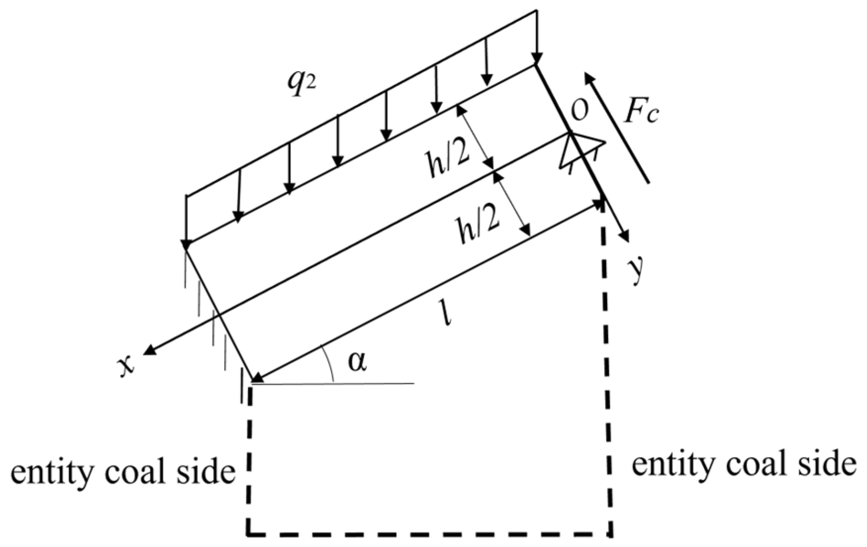
Uniform load q2 and lateral force Fc from adjacent coalThe main boundary conditions on the upper and lower sides and the small boundary conditions on the left and right sidesFixed support at low-sidewall coal, simple support at high-sidewall coal
Table 3. Mechanical hypothesis of main roof structure in roadway-retaining period.
LoadBoundary ConditionsSupport Assumptions
Uniform load q3 and lateral force FN from collapsed rock block BThe main boundary conditions on the upper and lower sides and the small boundary conditions on the left and right sidesFixed support at low-sidewall coal, free end over goaf
Table 4. Mechanical hypothesis of main roof structure in advanced influence period of the second mining.
LoadBoundary ConditionsSupport Assumptions
Uniform load q4, lateral force FN, and goaf support FsThe main boundary conditions on the upper and lower sides and the small boundary conditions on the left and right sidesFixed support at low-sidewall coal, simple support from compacted goaf
Table 5. Stress maximum and deflection peak.
Stress Maximum/MPaDeflection Peak/mm
25°30°35°40°45°25°30°35°40°45°
Roadway excavation period63.3863.3661.859.957.554.79.18.28.07.46.96.4
The advanced influence period of the first mining activity112.474.865.355.345.034.296.948.042.231.620.69.6
Roadway retaining period286.8218.5199.5179.0157.1134.0353.8267.8243.8218.1190.6161.7
The advanced influence period of the second mining activity374.3256.9225.2191.1154.6116.2485.4342.1302.2259.2213.5165.3
Disclaimer/Publisher’s Note: The statements, opinions and data contained in all publications are solely those of the individual author(s) and contributor(s) and not of MDPI and/or the editor(s). MDPI and/or the editor(s) disclaim responsibility for any injury to people or property resulting from any ideas, methods, instructions or products referred to in the content.

