Article

Experimental Investigation into the Mechanical Performance of Foam-Filled 3D-Kagome Lattice Sandwich Panels

by
Zhangbin Wu
1,2,
Qiuyu Li
1,2,
Chao Chai
3,
Mao Chen
1,2,
Zi Ye
1,2,
Yunzhe Qiu
1,2,
Canhui Li
1,2 and
Fuqiang Lai
1,2,*
1
School of Mechanical Engineering and Automation, Fuzhou University, Fuzhou 350116, China
2
Institute of Metal Rubber & Vibration Noise, Fuzhou University, Fuzhou 350116, China
3
China State Shipbuilding Corporation Fenxi Heavy Industry Co., Ltd., Taiyuan 030027, China
*
Author to whom correspondence should be addressed.
Symmetry 2025, 17(4), 571; https://doi.org/10.3390/sym17040571
Submission received: 12 March 2025 / Revised: 1 April 2025 / Accepted: 7 April 2025 / Published: 9 April 2025
(This article belongs to the Special Issue Symmetry/Asymmetry in Mechanics of Materials)

Abstract

:
3D-Kagome lattice sandwich panels are mainly composed of upper and lower panels and a series of symmetrically and periodically arranged lattices, known for their excellent high specific stiffness, high specific strength, and energy absorption capacity. The inherent geometrical symmetry of the 3D-Kagome lattice plays a crucial role in achieving superior mechanical stability and load distribution efficiency. This structural symmetry enhances the uniformity of stress distribution, making it highly suitable for automotive vibration suppression, such as battery protection for electric vehicles. In this study, a polyurethane foam-filled, symmetry-enhanced 3D-Kagome sandwich panel is designed following an optimization of the lattice structure. A novel fabrication method combining precision wire-cutting, interlocking core assembly, and in situ foam filling is employed to ensure a high degree of integration and manufacturability of the composite structure. Its mechanical properties and energy absorption characteristics are systematically evaluated through a series of experimental tests, including quasi-static compression, three-point bending, and low-speed impact. The study analyzes the effects of core height on the structural stiffness, strength, and energy absorption capacity under varying loads, elucidating the failure mechanisms inherent to the symmetrical lattice sandwich configurations. The results show that the foam-filled sandwich panels exhibit significant improvements in mechanical performance compared to the unfilled ones. Specifically, the panels with core heights of 15 mm, 20 mm, and 25 mm demonstrate increases in bending stiffness of 47.3%, 53.5%, and 51.3%, respectively, along with corresponding increases in bending strength of 45.5%, 53.1%, and 50.9%. The experimental findings provide a fundamental understanding of foam-filled lattice sandwich structures, offering insights into their structural optimization for lightweight energy-absorbing applications. This study establishes a foundation for the development of advanced crash-resistant materials for automotive, aerospace, and protective engineering applications. This work highlights the structural advantages and crashworthiness potential of foam-filled Kagome sandwich panels, providing a promising foundation for their application in electric vehicle battery enclosures, aerospace impact shields, and advanced protective systems.

1. Introduction

The pursuit of lightweight, high-strength, and energy-absorbing materials in automotive and aerospace fields has intensified research into sandwich structures based on periodic metal distribution (PCM) [1]. Among these, symmetrically arranged lattice-based sandwich panels, featuring geometrically symmetric and periodically distributed metal struts between the panels, have garnered significant attention due to their superior specific stiffness, strength, and energy absorption capacity [2]. In particular, 3D-Kagome lattice configurations exhibit high shear resistance and excellent out-of-plane compressive performance, making them promising candidates for crashworthiness applications [3].
The integration of lightweight and high-strength composite materials has emerged as an effective strategy to meet the dual demands of weight reduction and crash safety in sections such as automotive battery packs and aerospace structures. Interlocking lattice sandwich structures, as a class of periodic porous materials, offer advantages including high specific strength, high specific stiffness, and cost-effective manufacturability [4]. These properties have led to their widespread application in the aircraft wings [5], brake discs [6], high-strength concrete [7], and automotive collision-absorbing boxes [8].
The 3D-Kagome lattice configuration, characterized by its intrinsic geometric symmetry, demonstrates remarkable potential for sandwich structure applications. This structural symmetry ensures uniform stress distribution and enhances stability, making it particularly effective for crashworthiness applications. Moreover, polyurethane foam filling enhances both mechanical performance and thermal dissipation properties, rendering these structures well-suited for advanced engineering applications [9]. The periodic and symmetrical arrangement of the lattice struts contributes to the even distribution of external loads, minimizing localized stress concentrations and improving energy absorption efficiency. As a result, symmetry-based lattice designs, such as the Kagome configuration, are increasingly explored for applications in high-impact environments, including automotive crash protection, aerospace shielding, and protective engineering.
Recent studies have explored various fabrication techniques and topological core designs to develop Kagome sandwich structures, accompanied by extensive mechanical characterization. Wang et al. [10] performed compression and shear tests on Kagome lattice sandwich panels produced via fusion mold casting, revealing that these structures exhibit higher strength and yield resistance compared to tetrahedral structures. Similarly, Lim et al. [11] introduced a novel triaxial braiding method for fabricating ideal trusses and analyzed the mechanical properties of tetrahedral and Kagome lattice sandwich panels under compression and bending loads, both theoretically and experimentally. Their findings indicate that failure primarily occurs through the plastic yielding of the struts under out-of-plane compression and bending. Notably, Kagome sandwich panels displayed dual peak loads in load–displacement curves, suggesting superior energy absorption capabilities.
Further advancements include the development of reinforced Kagome lattice configurations. Gautam et al. [12] optimized the Kagome structure, resulting in improved compressive performance compared to traditional lattices of the same density, as demonstrated through experimental and numerical analysis. The research group led by Prof. Kang at Chonnam National University, South Korea [13,14,15,16,17,18], extensively investigated the out-of-plane compression, in-plane shear, and bending properties of stainless steel Kagome lattice structures fabricated using braiding techniques, leading to successful applications across various engineering domains. Additionally, Song et al. [19] studied the effects of different structural dimensions through bending tests, analyzed the influence of structural dimensions on bending stiffness and sandwich density, revealed the variation laws of bending stiffness and strength of sandwich structures, and determined the optimal size design ratio.
In parallel, Li et al. investigated the dynamic response and failure mechanisms of CFRP-based Kagome lattice sandwich panels under low-velocity impact, revealing that both face sheet stiffness and core geometry significantly affect energy absorption behavior and damage modes [20]. Their findings offer valuable insights for improving crashworthiness in composite lattice systems. Moreover, Habashneh et al. introduced a reliability-based topology optimization framework considering geometrical imperfections and load position uncertainty, emphasizing the importance of robustness and probabilistic design strategies for advanced sandwich structures subjected to variable loading conditions [21].
Despite these advancements, current research on foam-filled Kagome lattice sandwich structures remains limited in key areas, with the influence of foam density and core height on mechanical failure mechanisms remaining underexplored. Comprehensive experimental validation of energy absorption efficiency (EAE) across compression, bending, and impact scenarios is lacking. Optimization strategies for tailoring foam-filled lattice structures for high-speed impact applications require further investigation.
This study proposes a novel 3D-Kagome lattice sandwich panel enhanced by polyurethane foam filling and manufactured using a hybrid technique involving precision wire cutting, interlocking core assembly, and in situ foam integration. Compared with conventional bonded or molded core designs, this interlocking configuration provides improved geometric control, manufacturing efficiency, and structural integration between the foam and lattice core.
The originality of this work lies in combining structural symmetry with advanced filling methods to develop crashworthy lattice sandwich structures with enhanced performance under multi-mode loading. The core contributions include fabrication and characterization of 304 stainless steel-based Kagome lattice sandwich panels filled with polyurethane (PU) foam, utilizing wire cutting, interlocking assembly, and adhesive bonding techniques. A systematic evaluation of mechanical properties, including compressive strength, flexural behavior, and impact resistance, is conducted under quasi-static and dynamic loading conditions. The influence of core height variations on load-bearing capacity, failure modes, and energy absorption efficiency (EAE) is analyzed.
The results demonstrate that the foam-filled 3D-Kagome structure significantly improves structural performance and energy dissipation capacity. These findings provide new insights for the design and optimization of lightweight crash-resistant structures, offering potential applications in electric vehicle battery protection, aerospace shielding, and high-impact defense systems.

2. Materials and Methods

2.1. Design of Kagome Interlocking Lattice Sandwich Structures

In this study, a novel Kagome-inspired lattice structure was developed using an interlocking assembly method. This innovative configuration, termed the ‘Kagome Interlocking Lattice Sandwich Structure’, offers advantages such as a simplified assembly process and cost-effective manufacturing. By incorporating polyurethane (PU) foam filling, a foam-filled interlocking lattice sandwich panel is produced, enhancing both mechanical performance and energy absorption capabilities.
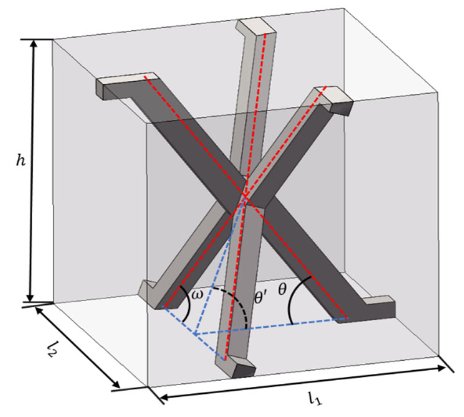
The unit cell of Kagome interlocking lattice sandwich structure consists of X-shaped struts and inclined struts, the two of which are joined together through a groove-based interlocking mechanism. The geometric configuration of the unit cell is depicted in Figure 1. The red dotted line in the figure represents the centerline of the structure. This structure exhibits a high degree of geometric symmetry, where the periodic arrangement of struts forms a uniform load-bearing network. The symmetrical nature of the Kagome lattice plays a crucial role in ensuring even stress distribution and minimizing localized deformation under loading conditions.
The spatial arrangement of the Kagome interlocking lattice core structure forms a rectangular unit cell, which is orderly and symmetrically distributed between the upper and lower face sheets. Specifically, the X-shaped struts form an angle of θ′ = 70.53° with the upper and lower panels, while the inclined struts form an angle of θ = 54.74° relative to the panels. Additionally, the X-shaped struts intersect at an angle of ω = 60°, as illustrated in Figure 2. The red dotted line in the figure is used to describe the shape of the rod to make the angle clearer. The angles shown in Figure 2—namely θ′ = 70.53°, θ = 54.74°, and ω = 60°—are determined from the spatial configuration of the interlocking Kagome lattice unit cell. These values correspond to the inclination angles between the X-shaped struts and the face sheets, as well as the intersection angles between diagonally crossing members, and are based on an idealized tetrahedral geometry.
The inherent symmetry of the Kagome structure enhances its mechanical efficiency by optimizing load transfer pathways, reducing stress concentrations, and improving structural stability. These characteristics make it particularly suitable for lightweight, impact-resistant applications in the automotive, aerospace, and defense sectors, where structural resilience and energy absorption are critical considerations.

2.2. Preparation of Foam-Filled Interlocking Lattice Sandwich Panels

The core and face sheets of the sandwich structure were fabricated from SUS304 stainless steel, chosen for its high strength and corrosion resistance, with a core thickness of 1.5 mm and a panel thickness of 0.5 mm. The lattice core struts have a thickness of 1.5 mm, while the face sheets have a thickness of 0.5 mm. The filling material consists of rigid polyurethane (PU) foam. To minimize the impact of the cutting process on material properties, X-shaped and W-shaped struts were precisely machined using electrical discharge machining (EDM). Following this, the struts were assembled via an interlocking groove mechanism to form the Kagome lattice core. The face sheets were then bonded to the assembled core using EAE-120HP metal adhesive produced by Loctite company in Yantai, China, and the completed sandwich structure was allowed to cure for 24 h to ensure optimal adhesion.
The polyurethane foam was prepared by mixing isocyanate and combined polyether in a 1:1 ratio, followed by thorough stirring with an electric mixer in the presence of a foaming agent. The liquid polyurethane mixture was then poured into square molds containing the Kagome interlocking sandwich structures. The foam was allowed to expand and cure for 12 h, ensuring the complete filling of the lattice core. The sample preparation process is illustrated in Figure 3. The red arrow in Figure 3a represents the removal of excess material through electrical cutting to produce a specific shaped rod. The red arrow in Figure 3b represents the assembly of two types of rods through grooves.
Uniaxial compression tests were performed on both the polyurethane (PU) foam and the adhesive specimens. The PU foam samples had dimensions of 100 × 300 × 25 mm, while the adhesive specimens were cylindrical, with a diameter of 46.5 mm and a height of 9.5 mm. Unloading was initiated when the loading displacement reached 8 mm. The resulting stress–strain curves are presented in Figure 4, and the corresponding compressive properties, including elastic modulus and peak stress, are summarized in Table 1.
Both foam-filled and unfilled sandwich panels were fabricated with core heights of 15 mm, 20 mm, and 25 mm. Representative samples of these sandwich panels are shown in Figure 5. The density variation in sandwich panels arises primarily from geometric differences in their unit cell configurations. By modifying the dimensions—width (t), length (l), and height (h)—the unit cell volume is determined. Since the full sandwich structure comprises a periodic array of these unit cells, its total volume can be derived, directly influencing the panel density. Additionally, the polyurethane infusion quantity significantly affects the structural filling ratio, introducing secondary density variations. The structural parameters of the foam-filled sandwich panel samples are detailed in Table 2, while those of the unfilled sandwich panel samples are listed in Table 3.

2.3. Methods of Mechanical Testing

2.3.1. Out-of-Face Compression Test

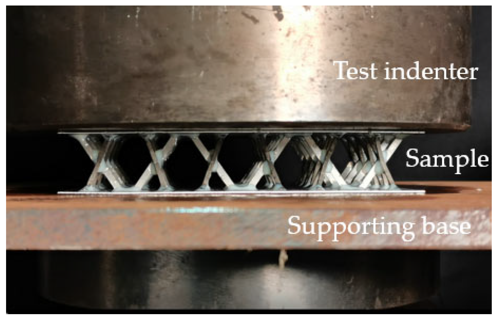
Following the ASTM C365/C365M-11 standard for planar compression testing [22], a preloading procedure was implemented by bringing the indenter into contact with the sandwich panel sample and applying a standardized preload of 45 N before zeroing the data. The compression tests were conducted using a WDW-T200 electronic universal testing machine by Jinan Tianchen Testing Machine company (Jinan, China), operating in displacement-controlled mode with a loading rate of 1 mm/min. The loading process was terminated upon observation of significant sample failure. The test setup is shown in Figure 6.
To ensure experimental reliability and reproducibility, three independent tests were conducted on samples of each height dimension, with the mean values adopted as the final results. The study primarily focused on evaluating the in-plane compressive behavior and failure mechanisms of the foam-filled interlocking lattice sandwich panels. Key mechanical responses, such as load–displacement curves, peak stress, and failure modes, were recorded and analyzed to assess the impact of foam filling and core height variations on structural integrity.

2.3.2. Three-Point Bending Test

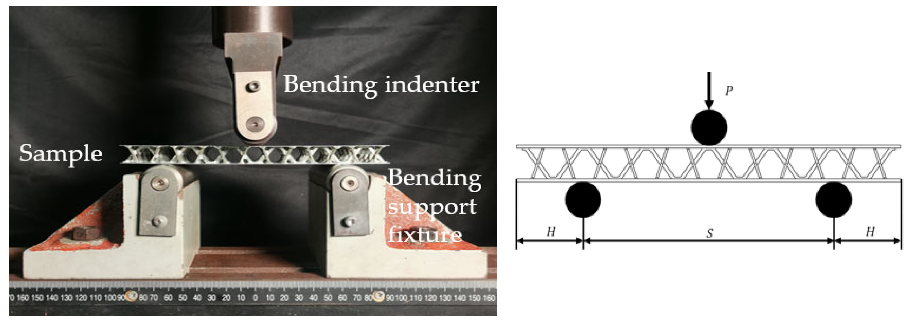
Following the ASTM C393/C393M-11 standard [23], the three-point bending tests were conducted using a WDW-T200 electronic universal testing machine in displacement-controlled mode at a loading rate of 1 mm/min. Before testing, proper alignment between the specimen and the indenter was ensured in accordance with ASTM C393. To prevent any displacement of the specimen prior to loading, a small preload of 10 N was applied through the indenter. This precaution may have introduced minor local deformation at the contact area. The experimental setup for the bending tests is illustrated in Figure 7. The test configuration was designed to evaluate the flexural stiffness, load-bearing capacity, and failure mechanisms of both foam-filled and unfilled interlocking lattice sandwich panels.
To ensure experimental reliability and reproducibility, three independent tests were conducted on samples of each height dimension, with the mean values adopted as the final results. The bending response of the specimens was analyzed based on key parameters such as maximum load, deflection, and failure modes. Special attention was given to the influence of core height and foam filling on the overall structural integrity and energy dissipation characteristics of the sandwich panels.

2.3.3. Low-Velocity Drop Hammer Impact Test

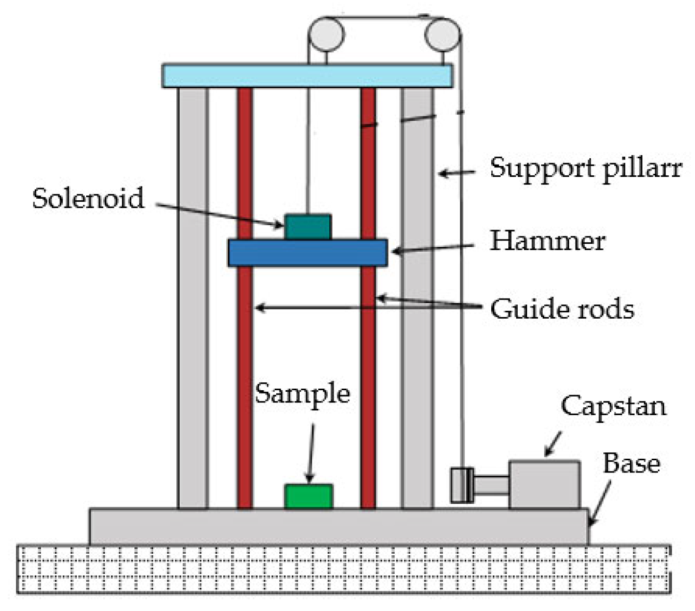
The low-velocity drop hammer impact tests were conducted in accordance with the ASTM D7136/D7136M-05 standard [24] to evaluate the impact resistance of the sandwich panels. A drop hammer with a mass of 76 kg was utilized to impact the sample at an initial velocity of 1.5 m/s, corresponding to a drop height of 115 mm and an impact energy of 85.5 J. The test setup is illustrated in Figure 8.
A high-precision magnetic grating displacement sensor (resolution: 0.01 mm) and a dynamic impact force sensor (capacity: 200 kN; resolution: 0.01 kN) were integrated into the drop hammer system to enable real-time monitoring of displacement and force signals during testing. To ensure data accuracy and repeatability, two repeated impact tests were conducted for each core height configuration. Precautions were taken to minimize excessive vibration in the sensor cables, which could otherwise affect signal stability. The impact tests were performed on both foam-filled and unfilled Kagome interlocking lattice sandwich panels to assess the influence of foam filling and core height on impact energy absorption. The peak impact force (PIF), deformation characteristics, and failure modes were recorded and analyzed to determine the effectiveness of the foam-filled lattice structure in mitigating impact loads. The impact performance metrics, including peak impact force, peak displacement, and energy absorption efficiency, were obtained based on the average values from two repeated tests.

3. Results and Discussion

3.1. Analysis of the Results of the Out-of-Face Compression Test

3.1.1. Compression Properties of Sandwich Panels

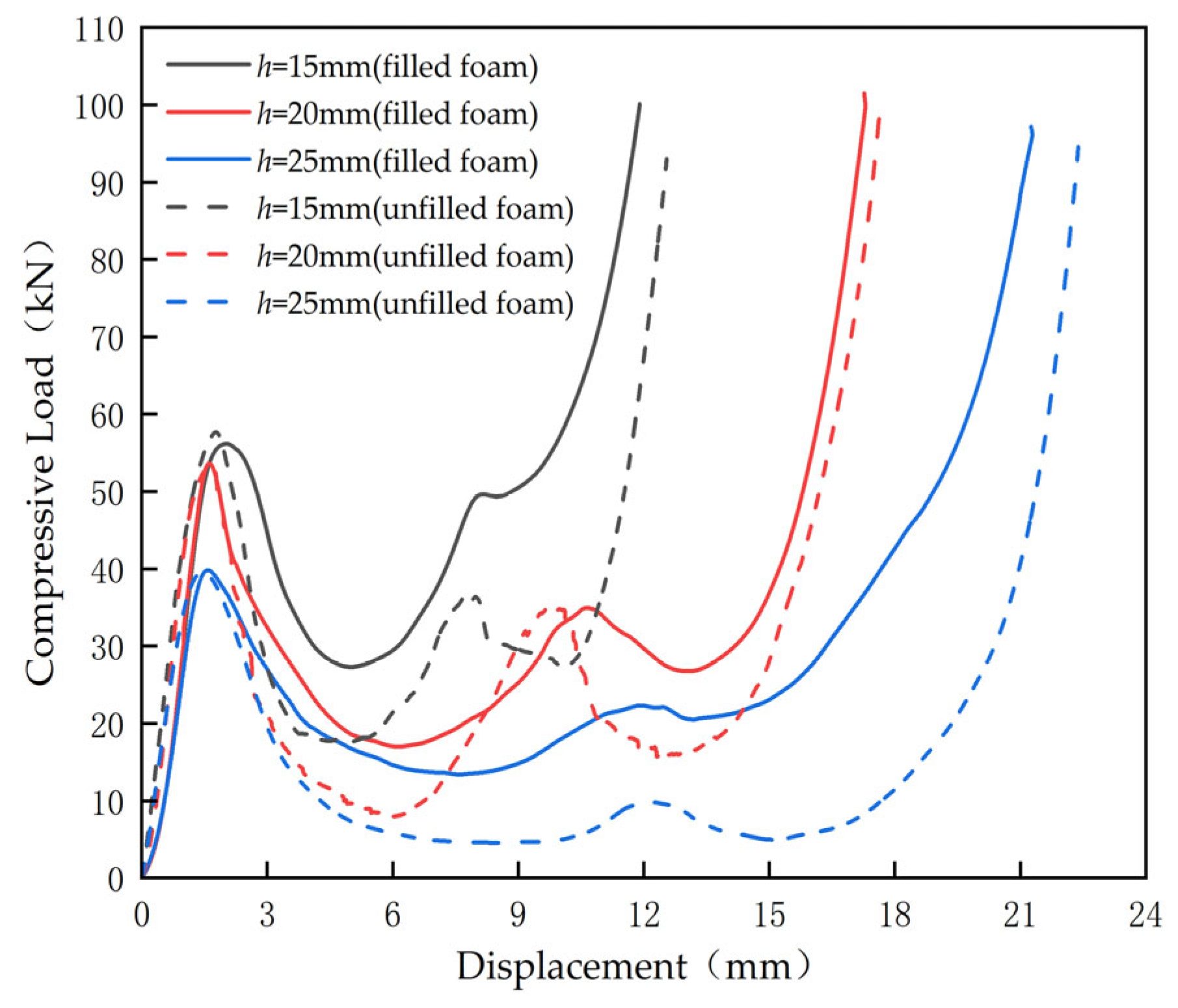
The mean load–displacement curves for both foam-filled and unfilled sandwich panels with three distinct core heights were experimentally obtained and are illustrated in Figure 9.
The analysis of the load–displacement curves reveals that sandwich panels with varying core heights exhibit similar deformation trends. The compression process of the sandwich structure can be categorized into three distinct stages: elastic, plastic, and densification. During the initial elastic stage, the compressive load increases linearly with displacement. Following this, partial core yielding occurs as the structure reaches its peak strength.
As the loading progresses, localized failure of the core and face sheets is accompanied by an audible crisp ringing sound, marking the onset of the softening phase. This results in the formation of the first plateau region, where partial strut softening occurs. The remaining intact struts continue to bear the load, generating a secondary wave followed by another softening region, forming the second plateau phase. Eventually, the core undergoes densification, characterized by a sharp increase in compressive load, which significantly enhances the load-bearing capacity of the sandwich panel. At this stage, complete core failure was observed, and the test was terminated.
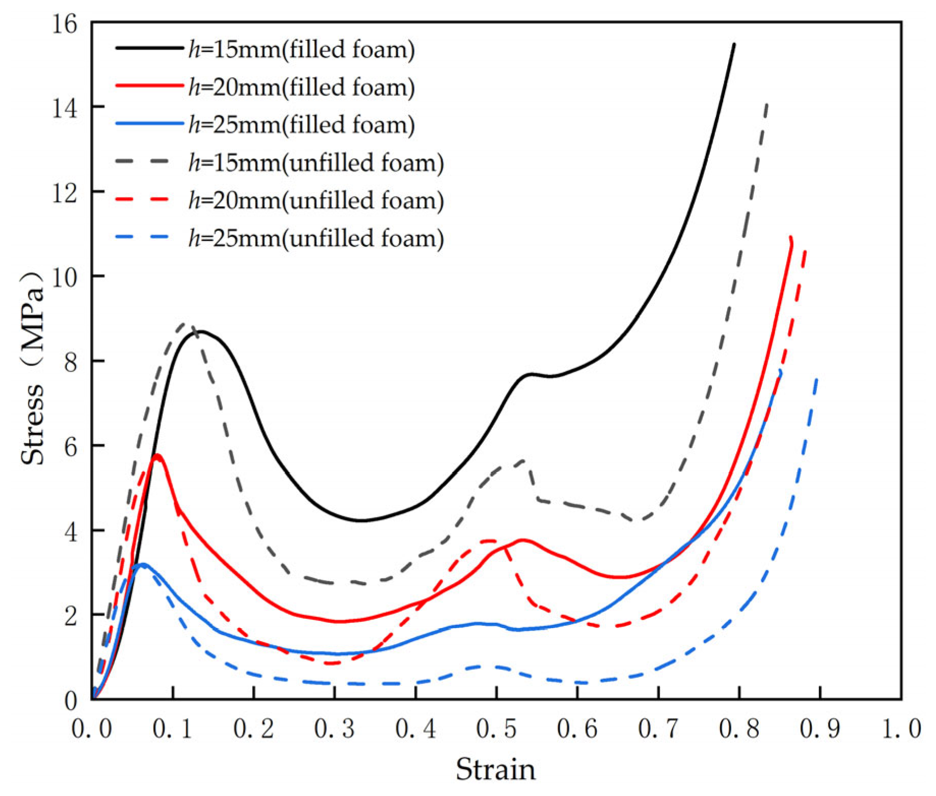
From the compressive load–displacement curves, the corresponding stress–strain curves were derived, as shown in Figure 10.
The compressive modulus was determined from the slope of the stress–strain curve within the elastic deformation region, in accordance with the standard for flatwise compression testing [18]. Specifically, the modulus was calculated over the strain range of 0.02 to 0.04, using the following expression:
E = σ 0.04 σ 0.02 0.02
where σ0.04 and σ0.02 represent the stresses corresponding to strains of 2% and 4%, respectively.
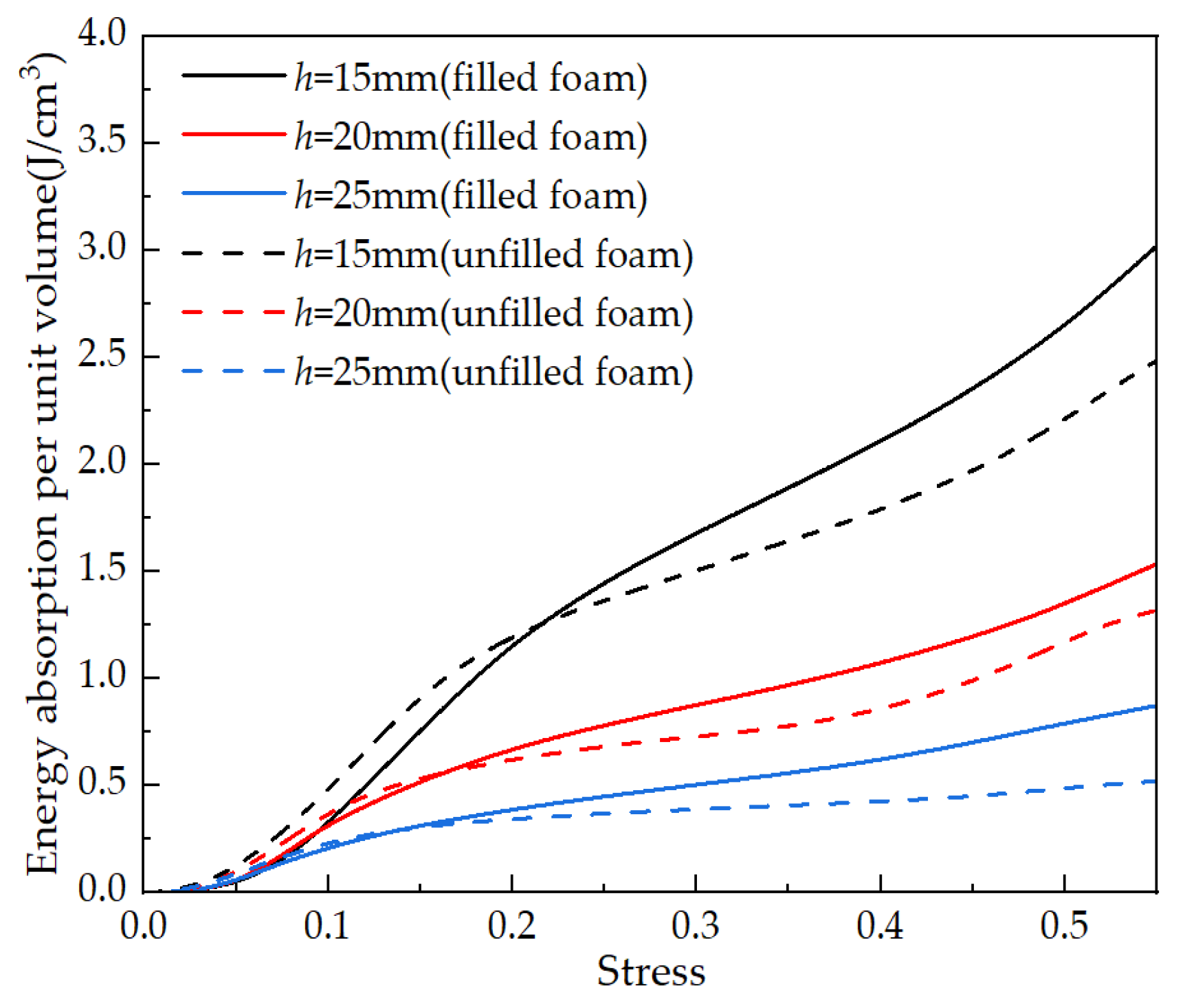
The stress–strain behavior of the sandwich panels provides insights into their energy absorption capacity. However, their validity is limited to a specific range. Thus, energy absorption characteristics were analyzed for structures that did not undergo complete failure prior to reaching a compressive strain of 55%. By integrating the data from Figure 10, the energy absorption per unit volume as a function of stress was derived, as illustrated in Figure 11.
Based on Figure 10 and Figure 11, three key mechanical parameters were extracted: elastic modulus, compressive strength, and energy absorption per unit volume, as presented in Table 4.
As shown in Table 4, the compressive modulus of the sandwich panels initially increases and then decreases with increasing core height. At a core height of 25 mm, the foam-filled sandwich panel exhibits a higher compressive modulus than its unfilled counterpart. Furthermore, the compressive strength of the panels decreases as the core height increases. Notably, at core heights of 20 mm and 25 mm, the foam-filled sandwich panels demonstrate greater compressive strength than the unfilled ones. Additionally, at a strain of 0.55, the energy absorption per unit volume of the foam-filled panels exceeds that of the unfilled panels, although it shows a decreasing trend with increasing core height. These findings suggest that the incorporation of polyurethane foam improves the compressive performance and energy absorption capacity of sandwich panels.

3.1.2. Damage Morphology of Sandwich Panels Under Compressive Loading

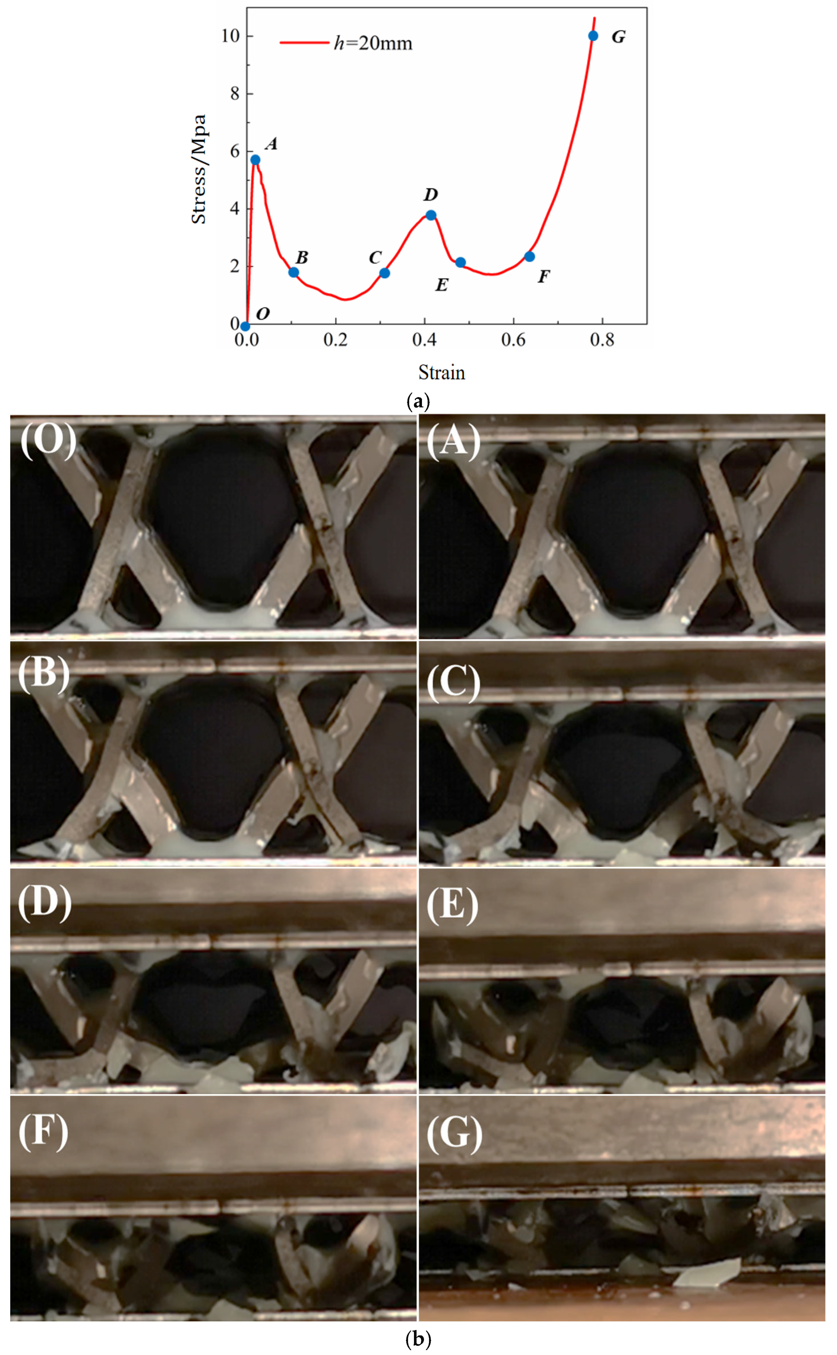
Since the polyurethane foam fully fills the sandwich panel pores, internal failure mechanisms are challenging to observe directly. However, given the consistent deformation behavior across panels with different core heights, the damage morphology analysis was conducted using a representative 20 mm core height sample, as shown in Figure 12.
As illustrated in Figure 12, the primary failure modes observed in the sandwich panels during compression include face-core debonding and strut deformation. The OA and CD segments of the stress–strain curve represent the elastic phase, where stress increases linearly, leading to gradual strut buckling and destabilization, corresponding to the peak stress observed in the curves. The AB and DE segments correspond to the plastic yielding stage, characterized by a gradual stress decline, accompanied by audible fracture of the adhesive and partial debonding between the core and face sheets. The BC and EF segments represent the softening and energy absorption phases, where the angle between struts and the horizontal plane decreases, leading to a plateau phase with minimal stress variation but increasing strain. Finally, in the FG segment, the densification stage begins, causing a sharp stress increase due to the expanded contact area between struts and face sheets, a phenomenon that significantly improves the load-bearing capacity of the sandwich panel.

3.2. Analysis of the Results of the Three-Point Bending Test

3.2.1. Bending Properties of Sandwich Panels

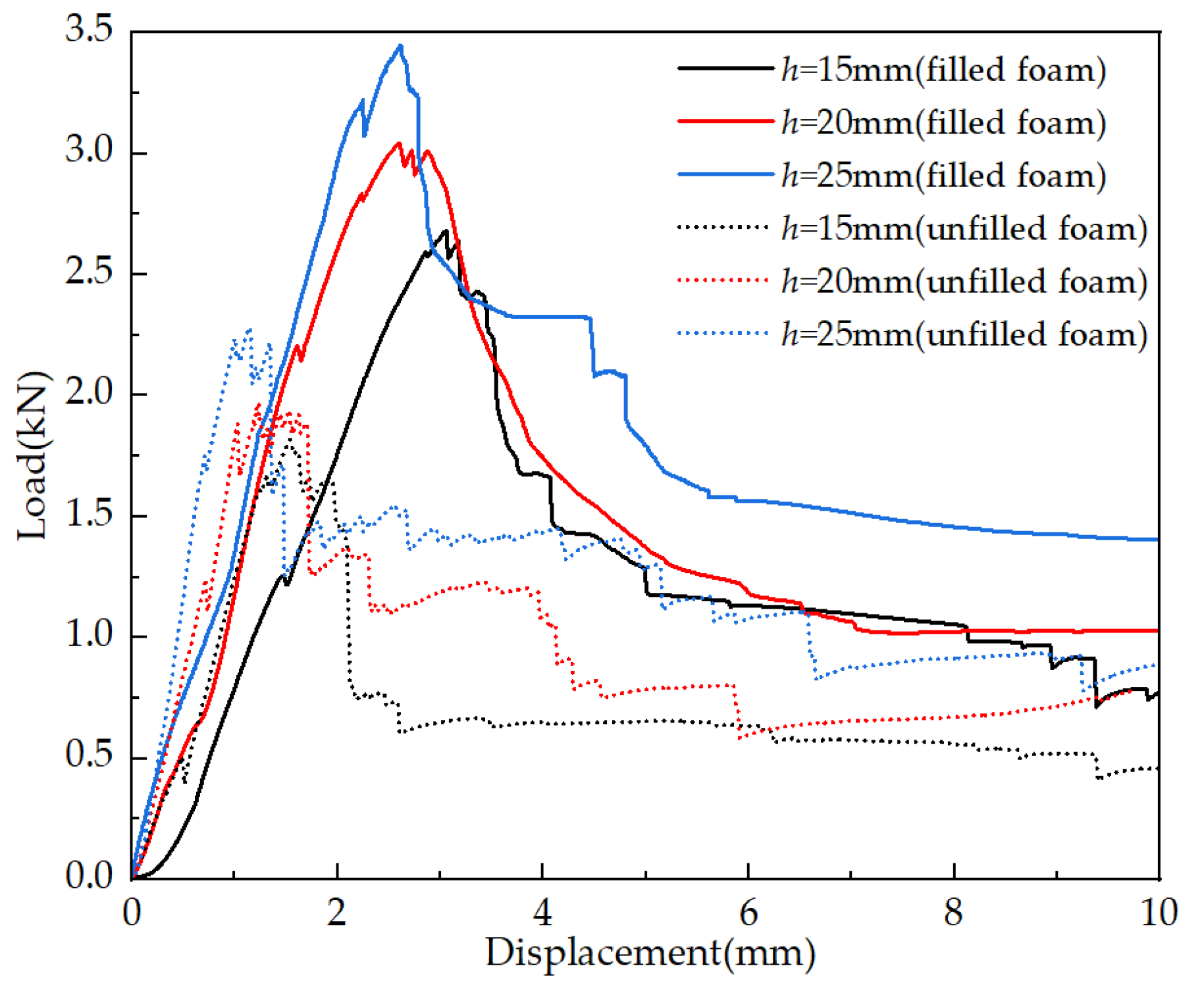
The load–displacement curves of the sandwich panels with varying core heights were experimentally measured and are illustrated in Figure 13. The overall trends of the curves remain consistent across different core heights, though minor fluctuations are observed due to variations in processing accuracy and bonding strength between the face sheets and core. The curves can be categorized into three distinct phases: linear zone, yield zone, and failure zone.
During the linear zone, the slope of the curve and the peak load increase with core height, whereas the corresponding displacement at failure decreases. Beyond the yield point, the curve enters a plateau zone, the magnitude of which increases with higher core height.
Under three-point bending conditions, the upper face sheet resists compressive forces, while the lower face sheet experiences tensile forces. The core mainly withstands shear stresses, with additional localized compressive stresses beneath the indenter. The bending stiffness (D) and bending strength (σf) were calculated using the following equations [25,26]:
D = P L 3 48 B w
σ f = P L 4 B t f ( h t f )
where D is the bending stiffness (N·mm), L is the span of the lower support of the bending device (mm), B is the width of the panel (mm), P is the applied bending load (N), σf is the bending strength (MPa), h is the panel height (mm), and tf is the face sheet thickness (mm).
The obtained bending stiffness and bending strength values are presented in Table 5.
The bending stiffness and bending strength of the polyurethane foam-filled samples exhibit a significant improvement compared to the unfilled samples, with bending stiffness increasing by 47.3%, 53.5%, and 51.3%, respectively, and the bending strength increasing by 45.5%, 53.1%, and 50.9%, respectively. This improvement is attributed to the enhanced energy absorption capacity of the polyurethane foam, which effectively reinforces the bending resistance of the sandwich panels.
Additionally, for both foam-filled and unfilled specimens, the bending strength consistently decreases as the core height increases from 15 mm to 25 mm. This indicates that while increasing core height improves bending stiffness due to an extended moment arm, it also introduces a greater risk of face-core debonding and local buckling, both of which can result in reduced bending strength. This behavior reflects a trade-off between stiffness and stability, where higher cores offer increased resistance to flexural deformation but become more susceptible to shear-induced interfacial failure and instability within the core.

3.2.2. Damage Morphology of Sandwich Panels Under Bending Loads

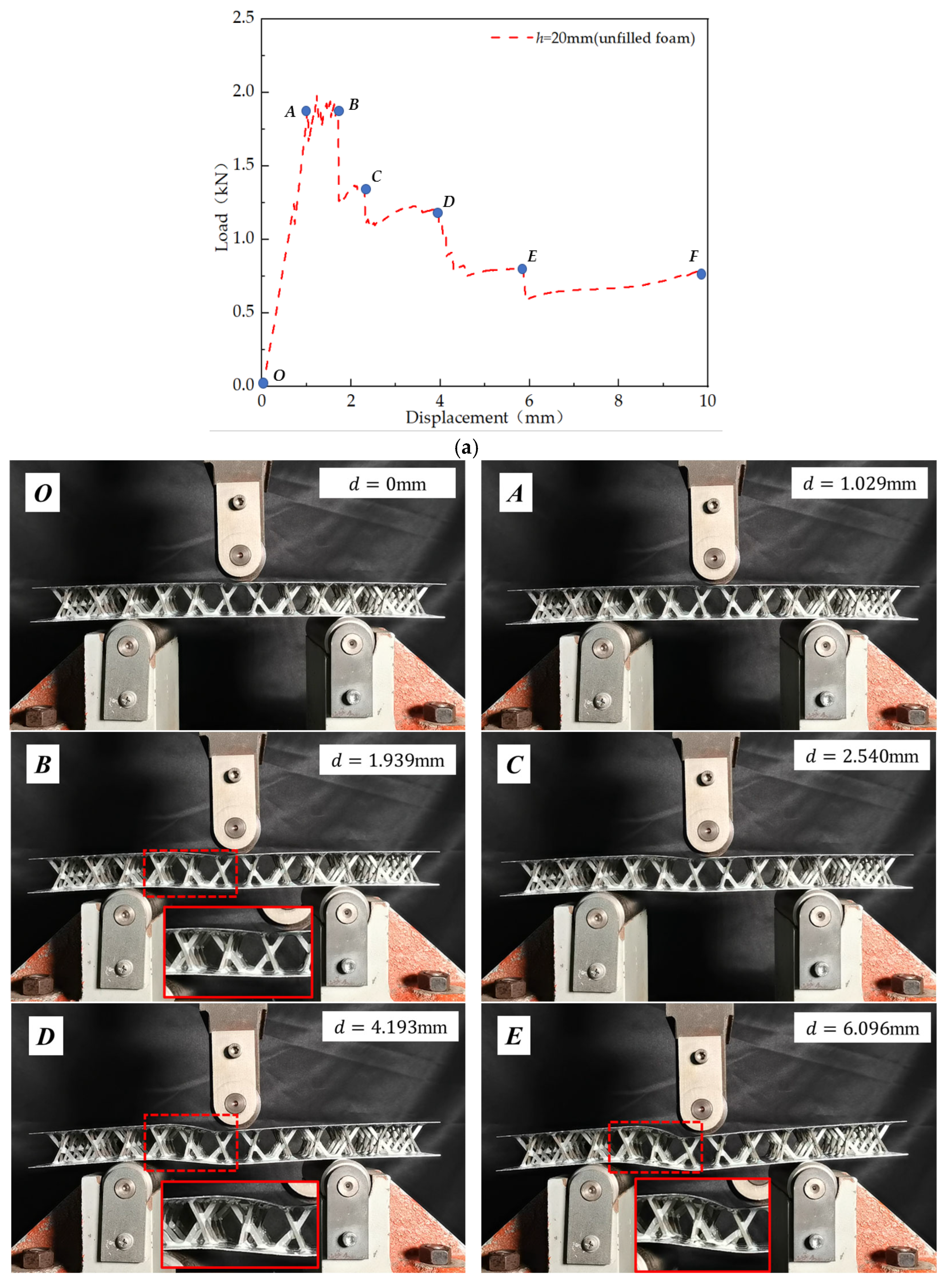
Since the polyurethane foam completely fills the sandwich panel, internal damage morphology is challenging to directly observe. Moreover, as the deformation process of sandwich panels with different core heights remains consistent during three-point bending tests, a 20 mm unfilled sandwich panel was selected as a representative sample for damage morphology analysis, as shown in Figure 14.
During loading, the sandwich structure exhibited three primary failure modes: face sheet wrinkling, core-face debonding, and strut deformation. All red bounding boxes in the figure indicate the failure area of the sandwich panel, and all red implementation boxes are enlarged of the failure area.
The OA segment represents the elastic deformation stage, where the structure deforms elastically under the applied load. Beyond point A, partial detachment of the X-shaped struts from the face sheets was observed, inducing serrated fluctuations in the curve between points A and B. At point B, debonding and yielding of the W-shaped struts and face sheets occurred, accompanied by a distinct fracture sound, marking the transition to the plastic yielding stage, as highlighted in the dashed box in Figure 14.
At points D, E, and F, progressive panel wrinkling, core-face debonding, and strut deformation were recorded, leading to a gradual decline in load-bearing capacity. Notably, at point E, the struts within the dashed box were fully debonded, with significant face sheet wrinkling. The EF segment represents the final failure stage, during which the structure experienced complete loss of integrity, as shown in Figure 14. The G in Figure 14b enlarges the failure area in label F.

3.3. Analysis of the Results of the Low-Velocity Drop Hammer Impact Test

3.3.1. Impact Resistance of Sandwich Panels

The impact force–time response curves of sandwich panels with different core heights are shown in Figure 15. The curves exhibit oscillatory variations, attributed to the ‘punch oscillation’ phenomenon [27], which arises when the natural frequency of the punch influences the impact response. If the impact sensor is not securely installed, this oscillation effect becomes more pronounced.
As shown in Figure 15, the impact load–time curves for sandwich panels with different core heights follow a distinct ‘mountain peak’ pattern. Notably, the h = 20 mm panel exhibits more pronounced fluctuations. The impact load initially increases to a peak, enters a fluctuation phase, and subsequently declines after reaching a second peak. This response suggests that the upper face sheet initially absorbs the impact energy upon collision with the falling hammer, with the impact load reaching its first peak as the panel reaches its damage threshold.
Subsequently, the core and polyurethane foam absorb the impact, and once the core fully fails, the lower face sheet begins to sustain the impact, causing the second peak in the impact load–time curve.
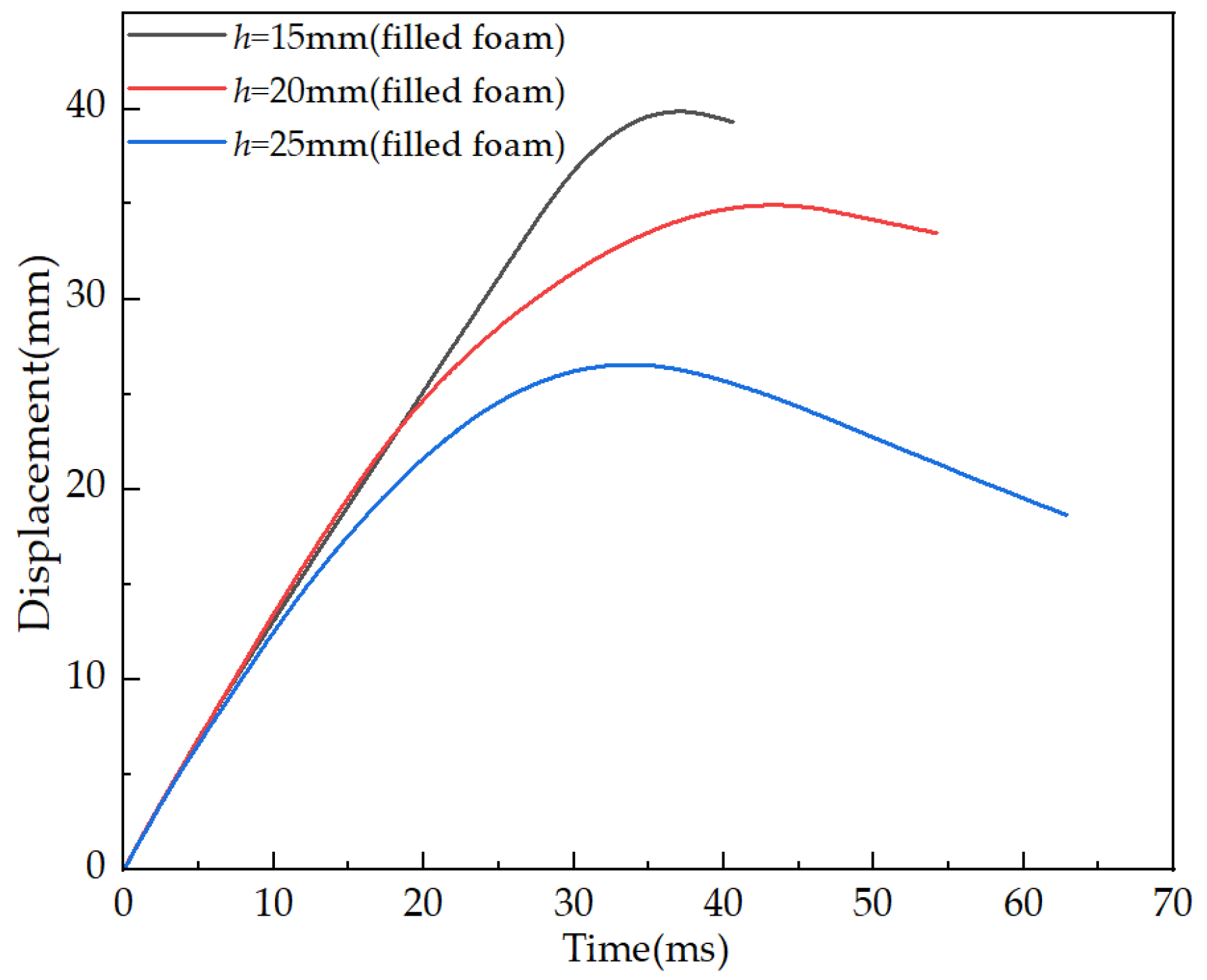
The displacement–time curves for sandwich panels with different core heights are shown in Figure 16. During the initial impact phase, the hammer strikes the central area of the specimen, causing localized deformation. The displacement–time curves for all three core height configurations exhibit a similar initial upward trend. However, specimens with greater core heights show a lower slope and smaller peak impact displacement, indicating enhanced stiffness. As the impact progresses, the hammer begins to rebound due to the restoring force provided by the sandwich panel. A higher core height leads to greater structural resistance, which, in turn, results in a more pronounced rebound displacement of the hammer.
This behavior suggests that increasing the core height enhances the structural capacity to absorb and redistribute impact energy. The higher the core, the greater the deformation length available for progressive collapse of the lattice and foam, a phenomenon that leads to reduced displacement and improved impact resistance. This trend is reflected in both the mechanical response and the observed failure morphology described in Section 3.3.2.
The analysis reveals that core height is inversely correlated with peak impact displacement—the higher the core, the lower the peak displacement. Additionally, an increase in core height results in an extended rebound duration and greater rebound displacement, indicating enhanced impact resistance.
By integrating the impact load–displacement curves from Figure 15, the absorbed energy–time curves for the sandwich panels were obtained, as shown in Figure 17.
The total impact energy imparted to the system was 85.5 J. The three panel configurations absorbed 14.61 J, 63.51 J, and 60.52 J, respectively, corresponding to energy absorption efficiencies of 17.1%, 74.3%, and 70.8%.
The impact performance parameters of foam-filled interlocking lattice sandwich panels with different core heights are summarized in Table 6. The results indicate that higher core heights lead to improved impact resistance.

3.3.2. Damage Morphology of Sandwich Panels Under Impact Loading

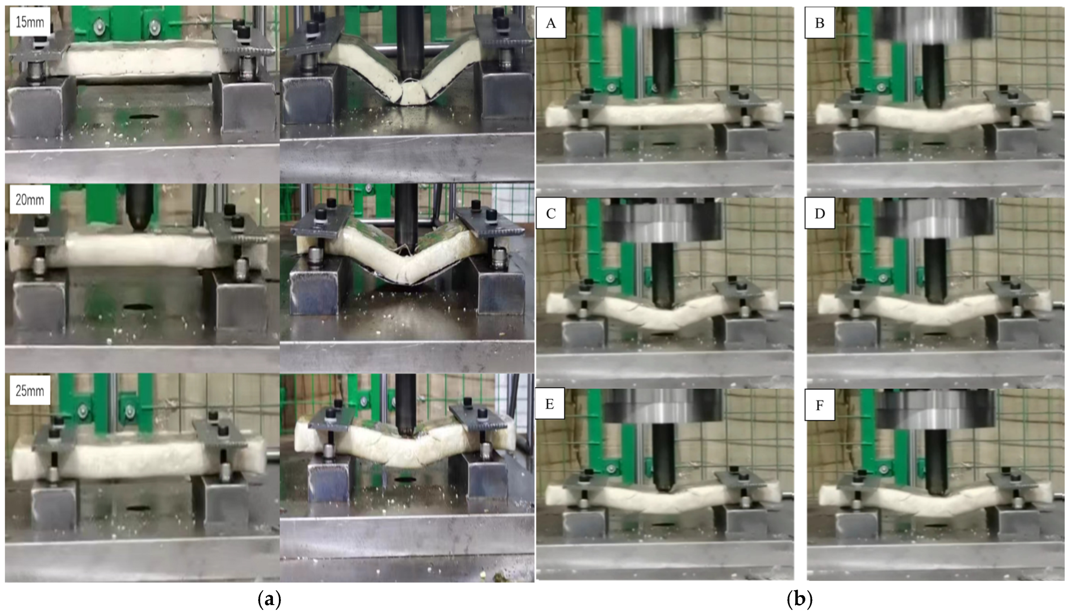
During impact testing, two primary failure mechanisms were observed: face sheet yielding and core compression. Figure 18 illustrates the damage morphology of the sandwich panels under impact loading.
The damage morphology of the three samples varies depending on the height of the core layer. The 15 mm panel demonstrates complete core crushing and densification in the central region, whereas the 20 mm panel exhibits localized core crushing and densification under equivalent loading conditions. In contrast, the 25 mm panel sustains minimal damage in the central zone, primarily characterized by lattice structure deformation, which enhances its energy absorption capacity. Furthermore, the foam-filled lattice structure facilitates effective impact force dissipation, mitigating abrupt structural collapse and improving load redistribution. For the h = 25 mm panel, shown in Figure 18b, the deformation process exhibits a progressive and continuous response, primarily characterized by sequential buckling of the core pillars and gradual densification. The central region of the core displays limited deflection, further confirming its enhanced energy absorption mechanism. This highlights the critical role of core height and foam filling in mitigating high-impact loads and optimizing structural resilience.
These findings reinforce the potential of foam-filled Kagome lattice sandwich structures in high-energy impact applications, such as automotive crash components and aerospace protective structures.

4. Conclusions

In this study, a foam-filled interlocking lattice sandwich structure was designed and fabricated, and its compressive, bending, and impact properties were systematically investigated. The key findings from the experimental analysis are summarized as follows:
(1)
Structural design and fabrication: the integration of a cutting–interlocking–gluing approach significantly streamlined the fabrication process of the foam-filled lattice sandwich panels, ensuring structural integrity and manufacturability. The Kagome lattice structure, with its periodic and symmetric arrangement, contributes to an even distribution of mechanical loads which enhances its structural stability and mechanical performance. The proposed hybrid manufacturing method combining precision wire-cutting, interlocking assembly, and in situ foam filling represents an innovative approach to improve structural integration and reproducibility of sandwich panels.
(2)
Compressive performance: the load–displacement curves obtained from compression testing revealed that panels with lower core heights exhibited superior compressive mechanical properties. The primary failure mechanisms observed were face-core debonding and strut deformation, with the foam-filled configurations exhibiting greater energy absorption efficiency and a more progressive failure process. The geometric symmetry of the Kagome lattice ensures uniform stress distribution during compression, leading to a more stable load-bearing response and improved energy absorption capacity.
(3)
Bending performance: the bending tests confirmed that bending stiffness increased with core height, while bending strength showed a decreasing trend with increasing core height. The primary failure modes included core debonding, face sheet wrinkling, and strut deformation. The foam-filled panels exhibited enhanced bending resistance, attributed to the stabilizing effect of the foam within the lattice structure. The symmetrical nature of the Kagome lattice enables balanced load transfer between the core and the face sheets, reducing localized stress concentrations and enhancing structural integrity under bending loads.
(4)
Impact resistance: drop hammer impact testing demonstrated that higher core heights correlated with increased peak impact force, reduced impact displacement, and enhanced impact resistance. Foam-filled sandwich panels exhibited improved energy absorption capacity, with the failure modes primarily consisting of panel bending and core compression. The symmetrical configuration of the Kagome lattice promotes effective energy dissipation by allowing the structure to deform progressively, distributing impact forces more evenly across the core and face sheets.
(5)
Overall mechanical efficiency: the results indicated that foam filling effectively enhanced the structural performance of interlocking lattice sandwich panels, improving load distribution, energy dissipation, and mechanical robustness under different loading conditions. The inherent symmetry in the lattice arrangement not only optimizes mechanical efficiency, but also improves impact resistance by ensuring a more uniform structural response under external loads. These enhancements confirm the synergy between structural symmetry and foam integration in improving mechanical behavior under complex load scenarios.
This study introduces a novel approach to lattice sandwich panel design by integrating symmetric geometric features with advanced foam-filling techniques. The findings from this study suggest that symmetry-enhanced foam-filled interlocking lattice sandwich panels possess excellent lightweight and crash-resistant properties, making them highly suitable for applications in electric vehicle (EV) battery protection, aerospace shielding, and defense impact-resistant designs. The demonstrated improvements in structural response and energy absorption capacity highlight the potential for tailoring such sandwich configurations in multifunctional, high-performance engineering systems. Moreover, the structural trends and failure mechanisms observed in this study—such as the effects of core height variation and foam filling—are expected to be extensible to other lattice geometries and material systems, offering guidance for broader engineering applications beyond the configurations tested. This study reinforces the importance of integrating symmetry-driven design strategies to enhance mechanical efficiency, load-bearing capacity, and failure resistance in advanced engineering structures.

Author Contributions

Conceptualization, methodology, and investigation, Z.W.; software, Q.L., C.L. and M.C.; validation, Z.W., C.C. and Y.Q.; formal analysis, F.L.; resources, Q.L., M.C. and Z.Y.; data curation, Q.L., C.L. and M.C.; funding acquisition, Z.W.; writing—original draft preparation, Q.L., Z.Y. and Y.Q.; writing—review and editing, Z.W.; visualization, F.L.; supervision, Z.W. All authors have read and agreed to the published version of the manuscript.

Funding

This work was supported by the Young and Middle-aged Teachers Education and Research Project (Science and Technology) of Fujian Province (No. JAT210022), the Starting Grants of Fuzhou University (No. GXRC-21052) and National Natural Science Foundation of China (Grant No. 52205185).

Data Availability Statement

The original contributions presented in this study are included in the article. Further inquiries can be directed to the corresponding author.

Acknowledgments

The authors would like to express sincere gratitude for the strong support from the three research projects listed in the Funding section. Additionally, we would like to thank former graduate student Zixu Jia and former undergraduate student Yunyi Chen for their valuable assistance with specimen fabrication and experimental testing during the course of this study.

Conflicts of Interest

The author Chao Chai is employed by the company China State Shipbuilding Corporation Fenxi Heavy Industry Co., Ltd. The remaining authors declare that the research was conducted in the absence of any commercial or financial relationships that could be construed as a potential conflict of interest.

References

  1. Cui, T.N.; Qin, Q.H. Ballistic performance of lightweight cellular sandwich structure: A review. Adv. Mech. 2023, 53, 395–432. [Google Scholar]
  2. Khan, S.A.; Rahman, M.A.; Khraisheh, M.; Hassan, I.G. Advances in 3D printed periodic lattice structures for energy research: Energy storage, transport and conversion applications. Mater. Des. 2024, 239, 112773. [Google Scholar] [CrossRef]
  3. Ullah, l.; Brandt, M.; Feih, S. Failure and energy absorption characteristics of advanced 3D truss core structures. Mater. Des. 2016, 92, 937–948. [Google Scholar] [CrossRef]
  4. Bin, H.; Lin, Z.W.; Jian, X.; Li, M.; Wen, Y.; Yang, J. Mechanical properties of a node-interlocking pyramidal welded tube lattice sandwich structure. Mech. Mater. 2019, 129, 290–305. [Google Scholar]
  5. Zaharia, S.M.; Enescu, L.A.; Pop, M.A. Mechanical Performances of Lightweight Sandwich Structures Produced by Material Extrusion-Based Additive Manufacturing. Polymers 2020, 12, 1740. [Google Scholar] [CrossRef] [PubMed]
  6. Hu, C.L.; Hong, W.H.; Xu, X.J.; Tang, S.F.; Du, S.Y.; Cheng, H.M. Sandwich-structured C/C-SiC composites fabricated by electromagnetic coupling chemical vapor infiltration. Sci. Rep. 2017, 7, 13120. [Google Scholar] [CrossRef] [PubMed]
  7. Ha, N.S.; Lu, G.X. A review of recent research on bio-inspired structures and materials for energy absorption applications. Compos. Part B-Eng. 2020, 181, 107496. [Google Scholar] [CrossRef]
  8. Al-Saedi, D.S.J.; Masood, S.H.; Faizan-Ur-Rab, M.; Alomarah, A.; Ponnusamy, P. Mechanical properties and energy absorption capability of functionally graded F2BCC lattice fabricated by SLM. Mater. Des. 2018, 144, 32–44. [Google Scholar] [CrossRef]
  9. Somarathna, H.M.C.C.; Raman, S.N.; Mohotti, D.; Mutalib, A.A.; Badri, K.H. The use of polyurethane for structural and infrastructural engineering applications: A state-of-the-art review. Constr. Build. Mater. 2018, 190, 995–1014. [Google Scholar] [CrossRef]
  10. Wang, J.; Evans, A.G.; Dharmasena, K.; Wadley, H.N.G. On the performance of truss panels with Kagome cores. Int. J. Solids Struct. 2003, 40, 6981–6988. [Google Scholar] [CrossRef]
  11. Lim, J.; Kang, K. Mechanical behavior of sandwich panels with tetrahedral and Kagome truss cores fabricated from wires. Int. J. Solids Struct. 2006, 43, 5228–5246. [Google Scholar] [CrossRef]
  12. Gautam, R.; Idapalapati, S. Performance of strut-reinforced Kagome truss core structure under compression fabricated by selective laser melting. Mater. Des. 2019, 164, 107541. [Google Scholar] [CrossRef]
  13. Lee, B.; Kang, K. A parametric study on compressive characteristics of wire-woven bulk Kagome truss cores. Compos. Struct. 2010, 92, 445–453. [Google Scholar] [CrossRef]
  14. Lee, M.G.; Yoon, J.W.; Han, S.M.; Suh, Y.S.; Kang, K.J. Bending response of sandwich panels with discontinuous wire-woven metal cores. Mater. Des. 2014, 55, 707–717. [Google Scholar] [CrossRef]
  15. Lee, M.G.; Hoang, V.M.; Yoon, J.W.; Han, S.M.; Suh, Y.S.; Kang, K.J. Compressive strength of wire-woven bulk Kagome with various orientations. Procedia Mater. Sci. 2014, 4, 329–334. [Google Scholar] [CrossRef]
  16. Lee, M.G.; Yoon, J.W.; Han, S.M.; Suh, Y.S.; Kang, K.J. Effects of gaps between discontinuous wire woven Kagome cores upon bending of sandwich panels. Procedia Mater. Sci. 2014, 4, 203–208. [Google Scholar] [CrossRef]
  17. Li, M.Z.; Kang, K.J. The compressive characteristics of the convex type wire-woven bulk Kagome truss PCM. In Proceedings of the KSME Conference, Jeju, Republic of Korea, 6–9 November 2024; The Korean Society of Mechanical Engineers: Seoul, Republic of Korea, 2008; pp. 138–143. [Google Scholar]
  18. Choi, D.H.; Lee, M.G.; Han, S.C.; Jeong, Y.C.; Cho, J.S.; Kang, K. Mechanical behavior of Microlattice with or without in-plane elements added on the outer faces. Int. J. Mech. Sci. 2018, 149, 311–325. [Google Scholar] [CrossRef]
  19. Song, S.J.; Xiong, C.; Tao, F.H.; Yin, J.H.; Zhang, Y.; Zhang, S. Size effect of composite Kagome honeycomb sandwich structure reinforced with PMI foams under quasi-static bending: Experiment tests and numerical analysis. Compos. Struct. 2022, 296, 115832. [Google Scholar] [CrossRef]
  20. Li, J.F.; Zhang, W.; Wang, Z.P.; Wang, Q.; Wu, T.X.; Qin, Q.H. Dynamic response and failure of CFRP Kagome lattice core sandwich panels subjected to low- velocity impact. Int. J. Impact Eng. 2023, 181, 104737. [Google Scholar] [CrossRef]
  21. Habashneh, M.; Cucuzza, R.; Aela, P.; Rad, M.M. Reliability-based topology optimization of imperfect structures considering uncertainty fo load position. Structures 2024, 69, 107533. [Google Scholar] [CrossRef]
  22. ASTM C365/C365M-11; Standard Test Method for Flatwise Compressive Properties of Sandwich Cores. ASTM International: West Conshohocken, PA, USA, 2011. Available online: https://www.antpedia.com/standard/6278552.html (accessed on 11 January 2025).
  23. ASTM C393/C393M-11; Standard Test Method for Core Shear Properties of Sandwich Constructions by Beam Flexure. ASTM International: West Conshohocken, PA, USA, 2011. Available online: https://www.antpedia.com/standard/6263326.html (accessed on 5 February 2025).
  24. ASTM D7136/D7136M-05; Standard Test Method for Measuring the Damage Resistance of a Fiber-Reinforced Polymer Matrix Composite to a Drop-Weight Impact Event. ASTM International: West Conshohocken, PA, USA, 2005. Available online: https://www.antpedia.com/standard/5704063.html (accessed on 12 March 2025).
  25. Zhu, P.Q. Research on The Collision Protection of Electric Vehicle Battery Box Based on The New Lattice Sandwich Structure. Master’s Thesis, Harbin Institute of Technology, Harbin, China, 2021. [Google Scholar]
  26. Zhang, H. Structural Analysis and Optimization of Foam-Filled Corrugated Sandwich Panels. Master’s Thesis, Jilin University, Jilin, China, 2018. [Google Scholar]
  27. Pei, Y.Y. Design and Mechanical Properties of Kagome Lattice Sandwich Composite Structure. Master’s Thesis, University of Chinese Academy of Sciences, Beijing, China, 2022. [Google Scholar]
Figure 1. Geometry of X-shaped struts and diagonal struts.
Symmetry 17 00571 g001
Figure 2. Geometric shape of the Kagome interlocking unit.
Symmetry 17 00571 g002
Figure 3. Preparation process of foam-filled interlocking lattice sandwich panel samples. (a) Core material EDM cutting. (b) Core assembly. (c) Panel and core bonding. (d) Foam padding.
Symmetry 17 00571 g003
Figure 4. Stress–strain of polyurethane foam and adhesive.
Symmetry 17 00571 g004
Figure 5. Sample sandwich panels with varying core heights.
Symmetry 17 00571 g005
Figure 6. Sandwich panel prototype and test setup.
Symmetry 17 00571 g006
Figure 7. Three-point bending test setup and sandwich panel samples.
Symmetry 17 00571 g007
Figure 8. Drop hammer impact test setup.
Symmetry 17 00571 g008
Figure 9. Compression load–displacement mean curve of sandwich panels.
Symmetry 17 00571 g009
Figure 10. Stress–strain curve for sandwich panels.
Symmetry 17 00571 g010
Figure 11. Energy absorption–strain curve per unit volume for sandwich panels.
Symmetry 17 00571 g011
Figure 12. Damage morphology analysis of a 20 mm sandwich panel under compression loading. (a) Stress–strain curves of 20 mm interlocking lattice sandwich panels. (b) Deformation process of sandwich panels under compression loading.
Symmetry 17 00571 g012
Figure 13. Bending load–displacement curves for sandwich panels.
Symmetry 17 00571 g013
Figure 14. Damage morphology analysis of sandwich panels under bending loads. (a) Load–displacement curves for 20 mm interlocking lattice sandwich panels. (b) Deformation process of sandwich panels under bending loads.
Symmetry 17 00571 g014aSymmetry 17 00571 g014b
Figure 15. Impact load–time curve for sandwich panels.
Symmetry 17 00571 g015
Figure 16. Displacement–time curve for sandwich panels.
Symmetry 17 00571 g016
Figure 17. Energy absorption–time curve for sandwich panels.
Symmetry 17 00571 g017
Figure 18. Morphological analysis of the damage to sandwich panels under impact loading. (a) Damage profiles of sandwich panels with different core heights. (b) Deformation process of 25 mm sandwich panel under impact loading. (A) Hammer-panel initial contact. (B) Panel core bends. (C) peak central bending. (D) core densification. (E) Falling hammer rebound. (F) Final panel form after impact.
Symmetry 17 00571 g018
Table 1. Compressibility of adhesive and polyurethane foam.
Material TypeCompressive Stiffness/MPaCompressive Strength/MPa
Adhesive4.9532.654
Polyurethane foam16.5782.995
Table 2. Structural dimensional parameters of foam-filled interlocking lattice sandwich panel samples.
Core Height
h/mm
Aspect Ratio of Struts l/tDensity
ρ/(kg/m3)
Core Mass m/gLength × Width of Panel/mm × mm
156.56868.0385.3365 × 200
208.75719.79134.0890 × 250
2510.94576.96576.96100 × 300
Table 3. Structural dimensional parameters of Kagome interlocking lattice sandwich panel samples.
Core Height h/mmAspect Ratio of Struts l/tDensity
ρ/(kg/m3)
Core Mass m/gLength × Width of Panel/mm × mm
156.56309.3532.2165 × 200
208.75213.5741.5190 × 250
2510.94155.7450.78100 × 300
Table 4. Compression performance parameters of sandwich panels.
Core Height
h/mm
Compressive Modulus
E/MPa
Compressive Strength
σ/MPa
Energy Absorption per Unit Volume
(J/cm3)
Foam filled or notFilledUnfilledFilledUnfilledFilledUnfilled
1561.66106.748.6878.9123.022.48
2077.87108.8765.7545.6871.531.32
2574.3670.5843.1883.1670.8730.519
Table 5. Bending performance parameters of sandwich panels.
Core Height
h/mm
Bending Stiffness/(N·m)Bending Strength/MPa
Foam-filled or notFilledUnfilledFilledUnfilled
151230.83835.86169.52116.53
201492.32971.97112.1973.28
251543.391019.9891.3450.54
Table 6. Impact performance parameters of sandwich panels of different core heights.
Core Height
h/mm
Peak Impact Load/kNMaximum Displacement/mmEnergy Absorption Efficiency (%)
152.0139.8517.1
203.0634.9374.3
253.7726.5470.8
Disclaimer/Publisher’s Note: The statements, opinions and data contained in all publications are solely those of the individual author(s) and contributor(s) and not of MDPI and/or the editor(s). MDPI and/or the editor(s) disclaim responsibility for any injury to people or property resulting from any ideas, methods, instructions or products referred to in the content.