1. Introduction
Compared with traditional plug-in charging methods, wireless power transmission technology has widely spread due to its security and convenience [
1]. Its applications in biomedical implants [
2,
3,
4,
5], consumer electronics [
6], underwater loads, electric vehicles (EVs) [
7,
8], and sightseeing cars [
9] have drawn much attention. With the wider application of the WPT system, higher requirements are put forward for the output power level and power quality of the system [
10].
The series–series (SS) compensation topology is widely applied in the WPT system, which benefits from its simple structure [
11] and feasibility [
12]. The equivalent load of the primary side is negatively correlated with the mutual inductance, so a higher output power with low mutual inductance can be transferred by the SS compensation topology. However, it also suffers from the overcurrent issue as the primary side behaves as if short-circuited when the receiver is open-circuited. The choice of the maximum current in the primary side coil is necessary for the safety of the SS compensation WPT system.
At present, the main purposes of the WPT system control focus on two aspects: maximum energy efficiency tracking (MEET) and maximum power point tracking (MPPT). For the MEET strategies, it is usually achieved by tracking the maximum output power point of the secondary side [
13] or the minimum input power point [
14] of the primary side. In [
15], the maximum efficiency output was also achieved by controlling the voltage ratio. Feedback signals from the receiver to the transmitter via a wireless communication system [
14] or Bluetooth [
16] are generally required to calculate the phase angle [
17] or the coupling coefficient [
18] in an SS compensation WPT system. However, an additional wireless communication system introduces extra volume and cost. To address this issue, the maximum efficiency transmission point of the tracking system is transformed into the minimum power input point of the tracking system by keeping the output voltage constant [
14]. The DC–DC converter of the secondary side is tuned to realize the output voltage as constant, while the primary side controller tracks the minimum power input point of the system. However, this strategy adds an extra conversion circuit. In [
19], the maximum efficiency tracking is achieved by switching the device network of the primary side, while the operating frequency of the system is always maintained at the optimal. To achieve maximum efficiency transmission, the load conditions are analyzed, and a method for tracking the maximum efficiency point of the system by adding an inductance network is proposed in [
20]. Although communication and additional converters of the primary and secondary sides in the aforementioned two methods are not necessary, in essence, the compensation circuit needs to be improved and adjusted. In [
21], when the mutual inductance is greater than a certain value, the optimal comprehensive energy efficiency is achieved by tracking the operation of the maximum output power of the SS compensation WPT system, according to the analysis of the output power and transmission efficiency. Therefore, the MPPT control mode is needed to take full advantage of SS compensation.
Most of the research focuses on the analysis of load characteristics and load matching, while control strategies are rarely discussed for the MPPT of an SS compensation WPT system. The characteristics of the optimal load for the maximum power transmission in an IPT system are analyzed in [
22]. The results demonstrate that the optimal load of an SS compensation IPT system is mainly determined by the quality factor of the primary side under tight coupling and of the secondary side under loose coupling. To extend the impedance-matching range, a novel impedance matching method based on the combined continuous conduction mode (CCM) and discontinuous conduction mode (DCM) operation of an impedance matching converter is proposed in [
23]. Based on this strategy, a maximum power transfer tracking method was developed, and the performance of an IPT system with a wider range of load and coupling coefficient variation adaptation was improved. With lower mutual inductance, SS compensation WPT systems transfer power with a higher level. Compared with a complex higher-order compensation topology, SS compensation WPT is suitable for more demanding applications due to its higher flexibility [
24], for example, the rail tram with high power requirements but limited space for a coupling mechanism. However, its behavior as a voltage source also puts forward higher requirements for the control strategy [
25]. At present, in the application process of a wireless charging system, it is mostly oriented to non-pure resistive loads such as supercapacitors [
26] and batteries [
27], and the load characteristics are more complex. Therefore, improving the dynamic performance of an SS compensation WPT system without any communication between the transmitter and the receiver is the key issue. In this article, an improved variable step-size maximum power point tracking control strategy with the mutual inductance identification for SS compensation WPT systems is proposed. Compared with the conventional P&O control, it can achieve a faster response and more accurate tracking, which is very important for the WPT for the rail transit. Without any communication between the transmitter and the receiver, the converters of the two sides are independently controlled to transfer high-level power and improve the dynamic performance of the system.
Nowadays, more and more intelligent control algorithms are also applied to the efficiency and power optimization of WPT systems. A wireless power transmission system is proposed based on the traditional wireless power transmission system; a wireless power transmission system is proposed to predict and stabilize the variable impedance so as to stably track the efficiency of the system in the resonant frequency range [
28]. The implementation of a machine learning (ML) strategy based on neural networks for the real-time range-adaptive automatic impedance matching of wireless power transfer (WPT) applications is discussed, aiming to achieve an effective automatic impedance matching over a wide range of relative distances [
29]. Three types of machine learning-based model-free controllers, i.e., an artificial neural network controller, a fuzzy logic controller, and a reinforcement learning-based deep
Q-network controller, are designed for HESS DC–DC converters aimed at tracking optimal power [
30]. However, there are many problems, such as strong data dependence and high cost of computing resources and time, and there is still a long way to explore the popularization and promotion of intelligent algorithms.
The application background of this paper is based on a rail tram, which requires sufficient power with limited size. The MPPT can be more meaningful and take full advantage of SS compensation. Firstly, the characteristics of an SS compensation WPT system were analyzed, and the relationship between the equivalent load of the secondary side and the mutual inductance was obtained with the system transferring the maximum output power. Furthermore, to realize the accurate identification of the mutual inductance without direct communication means between the transmitter and the receiver, a method of the mutual inductance identification based on the weight of parameter sensitivity was proposed. Based on the results of the identified mutual inductance, to make the system transfer the maximum power, the duty ratio of the receiver was adjusted to approach the corresponding equivalent load. To deal with the change of the mutual inductance, a condition of terminating the searching process of the maximum power point and re-identifying the mutual inductance was proposed. Finally, the control strategy was verified by both simulation and experiment. The advantage of an SS compensation WPT system was fully realized by the proposed control strategy, and the dynamic performance was improved with shorter settling time and more accurate maximum power point tracking.
The advantages of this article are reflected in the following aspects:
- (1)
Power: maximum output power tracking achieved to ensure the system power level.
- (2)
Efficiency: in the case of the mutual inductance level, the system tracks the maximum output power while ensuring transmission efficiency.
- (3)
Cost: communication between the transmitter and the receiver is not required. No communication equipment required, saving costs.
- (4)
Design complexity: the power conversion circuit is the basic structure; the system design is not complicated.
- (5)
Accuracy: no climbing process; fast and accurate tracking.
For SS WPT systems, the features of previous papers and this paper are listed in
Table 1.
2. Characteristic Analysis of SS Compensation WPT Systems
2.1. Circuit Topology Design
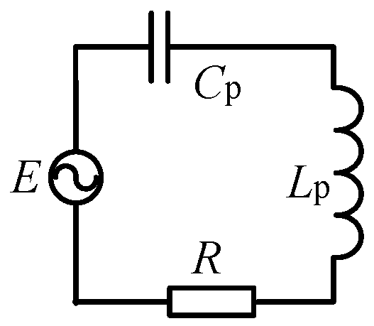
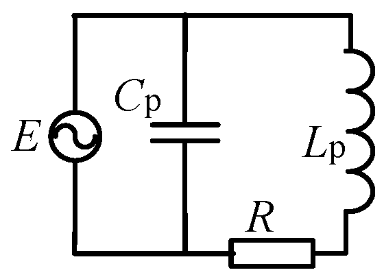
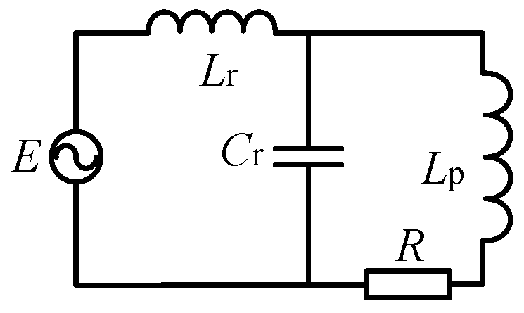
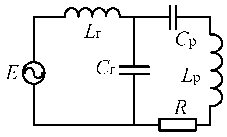
A conventional SS compensation WPT system consists of an inverter at the transmitter side to maximize the overall system efficiency typically by phase control or frequency control, and a DC–DC converter at the receiver side to regulate the charging current and voltage of the battery load. Several common resonance compensation topological characteristics are shown in
Table 2.
In the table, Lr, Cr and Cp are the resonance compensation elements, Lp is the coil inductance, R represents the load resistance, ω is the resonant angular frequency, and P is the active power on the load resistance R. The coil plays an important role in energy transfer and often uses a large amount of wire. Therefore, the self-inductance Lp is larger (usually about 100 μH), and the operating frequency is higher (20–50 kHz), and the coil equivalent impedance ωLp is much larger than the load resistance R. The application background of this paper is based on a rail tram. Due to the limited installation space of a coupling mechanism under the tram, the coupling mutual inductance is low, therefore, the voltage of the secondary side is also low. In order to output a higher level of power at a lower mutual inductance, the SS resonance compensation topology was selected. The receiving side adopted the boost converter to improve the output voltage level and meet the output demand.
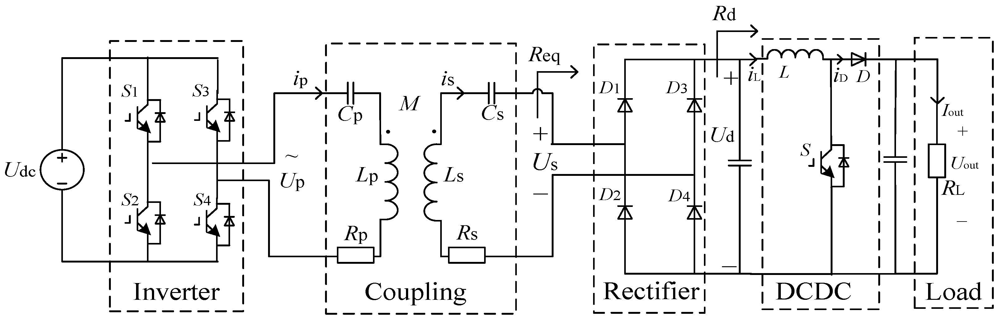
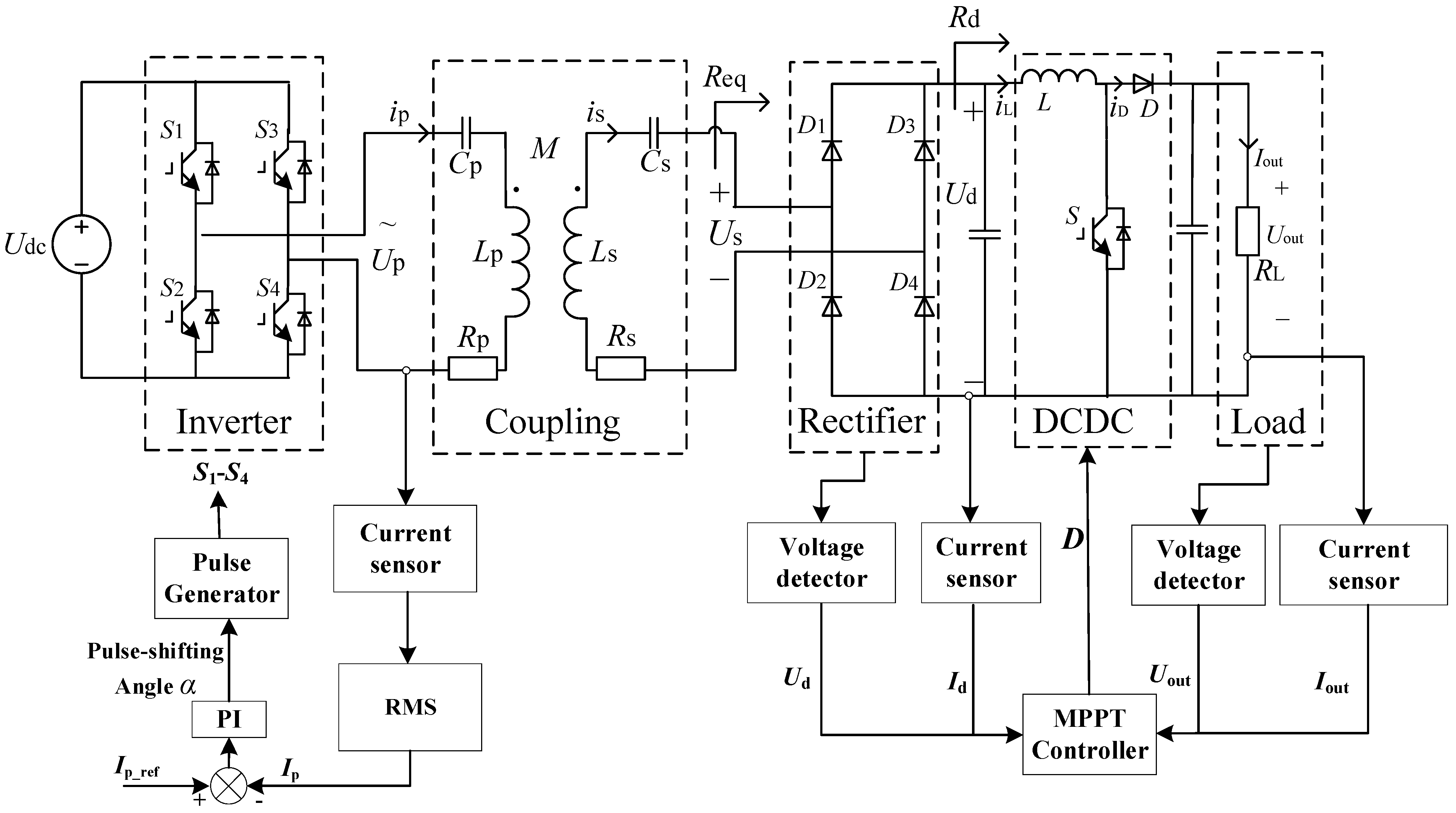
The basic structure of SS compensation WPT systems is depicted in
Figure 1.
Udc is the DC bus voltage. It is converted to high-frequency AC by an Inverter. Based on the principle of electromagnetic induction, the high-frequency induction voltage is coupled to the secondary side by a Coupling mechanism to realize wireless power transmission. The induced high-frequency AC voltage is rectified by a Rectifier to obtain the DC voltage, and then the voltage is adjusted by the DCDC circuit to supply energy to the load.
Up and Ip are the high-frequency AC voltage and current at the primary side. Us and Is are the induced voltage and current at the secondary side. The mutual inductance between the primary and the secondary sides is denoted as M. Lp and Ls denote the self-inductance of the primary and secondary coils, respectively. Meanwhile, Cp and Cs denote the series resonant capacitors. Rp is the equivalent series resistance (ESR) of the primary side (including the self-inductance Lp and the resonant capacitor Cp), while Rs is the ESR of the secondary side with the self-inductance Ls and the resonant capacitor Cs. Req, Rd, and RL are the equivalent resistance of the rectifier, DC–DC converter, and the load resistance, respectively.
2.2. Analysis of the Basic Parameters
To compensate the self-inductance of coils at both the primary side and the secondary side,
Cp and
Cs should satisfy the following requirement:
where
ω = 2π
f is the system operating angular frequency and
f is the system operating frequency.
The equivalent resistance can be expressed as follows:
where
D is the duty ratio of the DC–DC converter.
The equivalent impedance of the primary side can be expressed as follows:
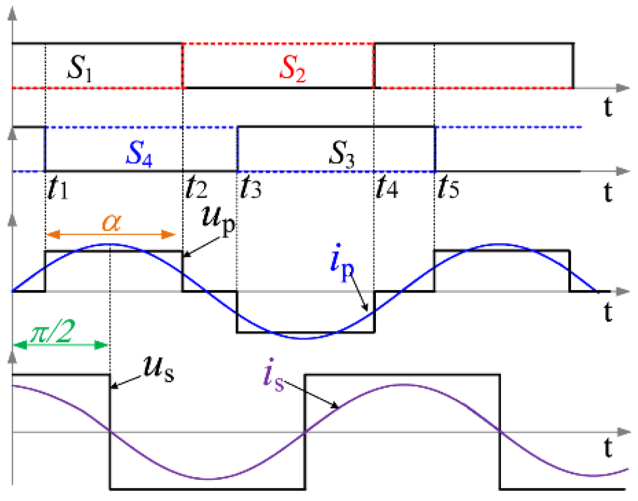
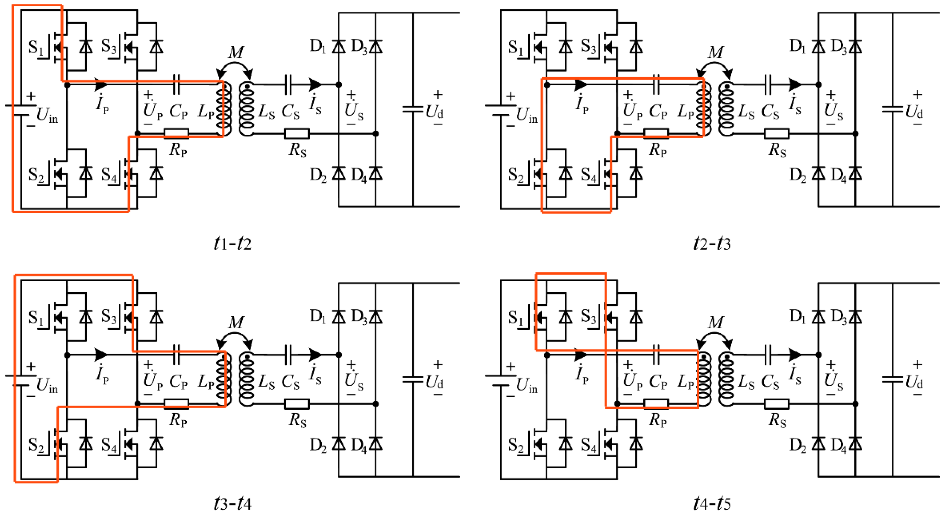
The fundamental harmonic approximation (FHA) method is used to analyze WPT systems since the resonant fundamental current is considerably larger than the harmonics due to the resonant network. The root mean square (rms) value of the inverter fundamental output voltage and the rms value of the primary current can be expressed as follows:
where
α is the conducting angle of the inverter. See “
Appendix A” for the formula derivation and current path of phase shift control.
By regulating α, the fundamental component of Up can be adjusted to suit the output voltage requirement with the varying load and mutual inductance.
For
α =
π, i.e., when the maximum primary voltage is reached, (4) results in:
In addition, the rms value of the primary current Ip also changes with the variation of the load and the mutual inductance.
Compared with other typologies, the output power of the SS compensation topology can be much higher with a relatively low mutual inductance. To fully take advantage of the SS compensation topology, the rms value of the current on the primary side should be kept maximum by regulating α.
Therefore, if
Ip =
Ipmax,
Up =
Upmax, that is:
According to (7), once the required equivalent load Req and the mutual inductance M are achieved, the maximum output power point of the system is located.
2.3. Analysis of Power and Efficiency
Based on the basic parameters above, the transmission efficiency and output power of the system can be expressed as follows:
According to Equation (7), the matching relationship between the equivalent load and the mutual inductance when the system output power is optimal can be obtained as follows:
By substituting Equation (10) into Equation (9), the expression of transmission efficiency under the condition of the maximum output power can be obtained.
In the range of the coupling mutual inductance
M > 0, there is always the following:
Therefore, when the mutual inductance M is greater than a certain efficient mutual inductance value, such as the mutual inductance value at η = 85%, the maximum power tracking can ensure that the transmission efficiency is always greater than 85%. While ensuring the power advantage of the system, the efficiency is also at a high level.
3. Mutual Inductance Identification Based on Parameter Sensitivity
It has been well-studied that the mutual inductance can be obtained by only measuring the voltage and the current on the primary side [
31]. However, during the actual operation of the system, the voltage and the current fluctuate to a certain extent, and the coupling mutual inductance identified is also different. Thus, in this section, a mutual inductance identification method based on parameter sensitivity is proposed to provide the basic parameters of the MPPT strategy. To maintain the system’s overall stability and performance, a wide range of coupling conditions caused by the arbitrary relative movement between the transmitter and the receiver should be considered during the coupling mechanism’s design process, i.e., the range of the mutual inductance [
Mmin,
Mmax] should be determined. Therefore, the range of the equivalent load [
Req1,
Req2] with respect to the variable mutual inductance should be calculated with (7) to achieve the MPPT.
When the equivalent load
Req is small, the system operates under the conditions of
Up =
Upmax and
Ip <
Ipmax. The input power, the output power, and the transmission efficiency can be expressed as follows:
When the equivalent load
Req is large, the system operates under the conditions of
Up <
Upmax,
Ip =
Ipmax. The input power, the output power, and the transmission efficiency can be expressed as follows:
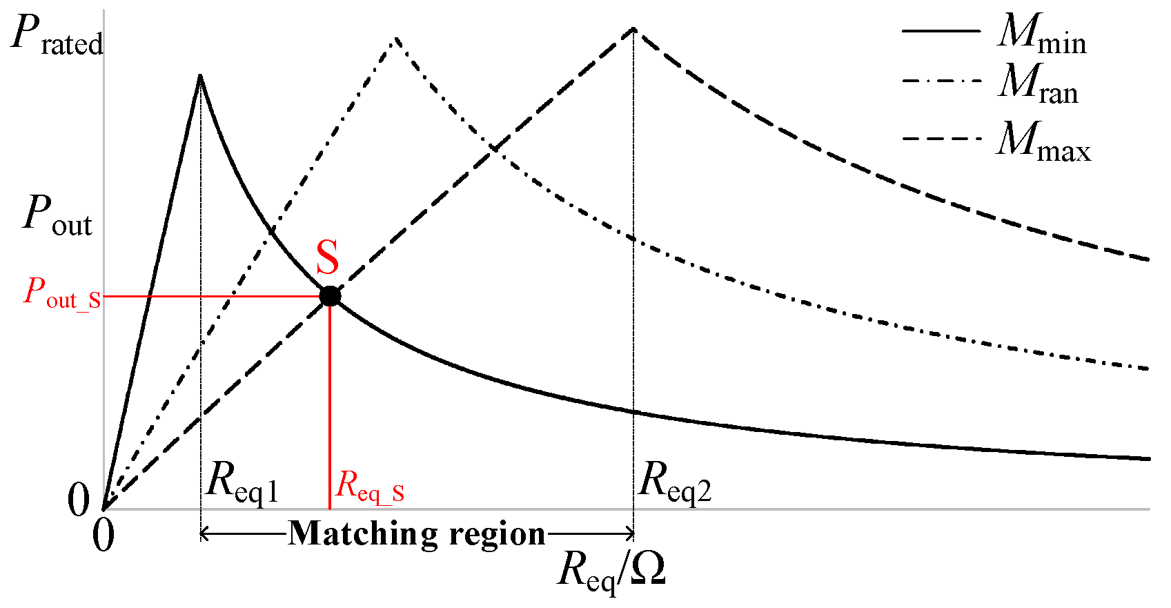
The output power profile varies with the equivalent load under different mutual inductance values as shown in
Figure 2.
Mmin and
Mmax are the minimum and maximum values of the variable mutual inductance, and
Mran is the random mutual inductance selected between
Mmin and
Mmax. It can be observed in the figure that in the equivalent load range of the matching area [
Req1,
Req2], to perform the accurate MPPT,
Req1 and
Req2 are the minimum resistance and the maximum resistance, respectively.
Therefore, it can be observed in
Figure 2 that in the matching region, the boundaries of which are determined by
Req1 and
Req2, there are two values of the mutual inductance with respect to a certain output power and the equivalent load. For example, the operating point S in the matching region can be determined by the output power
Pout_S and the equivalent load
Req_S, but there are two values of the mutual inductance,
Mmin and
Mmax, accordingly.
However, in the regions (0, Req1) and (Req2, +∞), there is only one mutual inductance, which is determined by the output power and the equivalent load. Therefore, identification of the mutual inductance should be realized in the regions of (0, Req1) and (Req2, +∞) with the output power and the equivalent load, correspondingly.
Accordingly, the mutual inductance identification equation can be expressed as follows:
Equations (19a) and (19b) is relatively complicated, with many variables. In addition, for a system with a high power level, the inertia is high, and the dynamic performance of the output power changing with the mutual inductance is poor. Therefore, compared with the output power, voltage and current are more suitable for the mutual inductance identification. The variation of the voltage and the current with the equivalent load under the different mutual inductance values mentioned above is shown in
Figure 3.
It can be seen that, similar to the output power, if the equivalent load is not in the matching region, the working point determined by
Us or
Is corresponds to a unique mutual inductance. Therefore, the mutual inductance identification equation can be obtained through voltage observation as follows:
It can also be obtained through current observation as follows:
Based on the above analysis, both Us and Is can be used for the mutual inductance identification. However, in practice, the real values drift away from the expected values. Thus, the mutual inductance identified by (20a,b) and (21a,b) is different.
The sensitivity analysis method can increase the reliability of the system analysis results and determine the main parameters and the secondary parameters according to the sensitivity of parameter changes. Therefore, in order to further improve the accuracy of parameter identification, a method based on parameter sensitivity weight combining voltage and current was proposed to obtain the mutual inductance.
The voltage and the current of the secondary side can be expressed as follows:
The parameter sensitivities
A and
B of the mutual inductance with respect to the voltage and the current of the secondary side can be expressed as follows:
Then, the parameter sensitivity weights
a and
b of the mutual inductance related to the voltage and current are obtained as follows:
Substituting (23) into (24) and then using Equations (20a,b) and (21a,b), the mutual inductance can be obtained as follows:
The initial equivalent load is generally high to ensure the safety of the startup process, and the secondary side can obtain the load change in real time through the measurement of voltage and current. Therefore, (25b) is adopted in the following sections.
4. Improved Variable Step-Size MPPT Control Strategy
Based on the relationship between the equivalent load and the mutual inductance, which is identified in
Section 3 at the maximum output power operating point in (7), an improved variable step-size MPPT control strategy without communication between the primary and secondary sides is proposed in this section.
4.1. Accurate Steady-State Tracking
Through the equivalent load, the relationship between the output power and the duty ratio of the DC–DC converter can be obtained as follows:
Assumption that the load
RL is constant in (26) and the output power varies with the duty ratio
D of the DC–DC converter under a certain mutual inductance is shown in
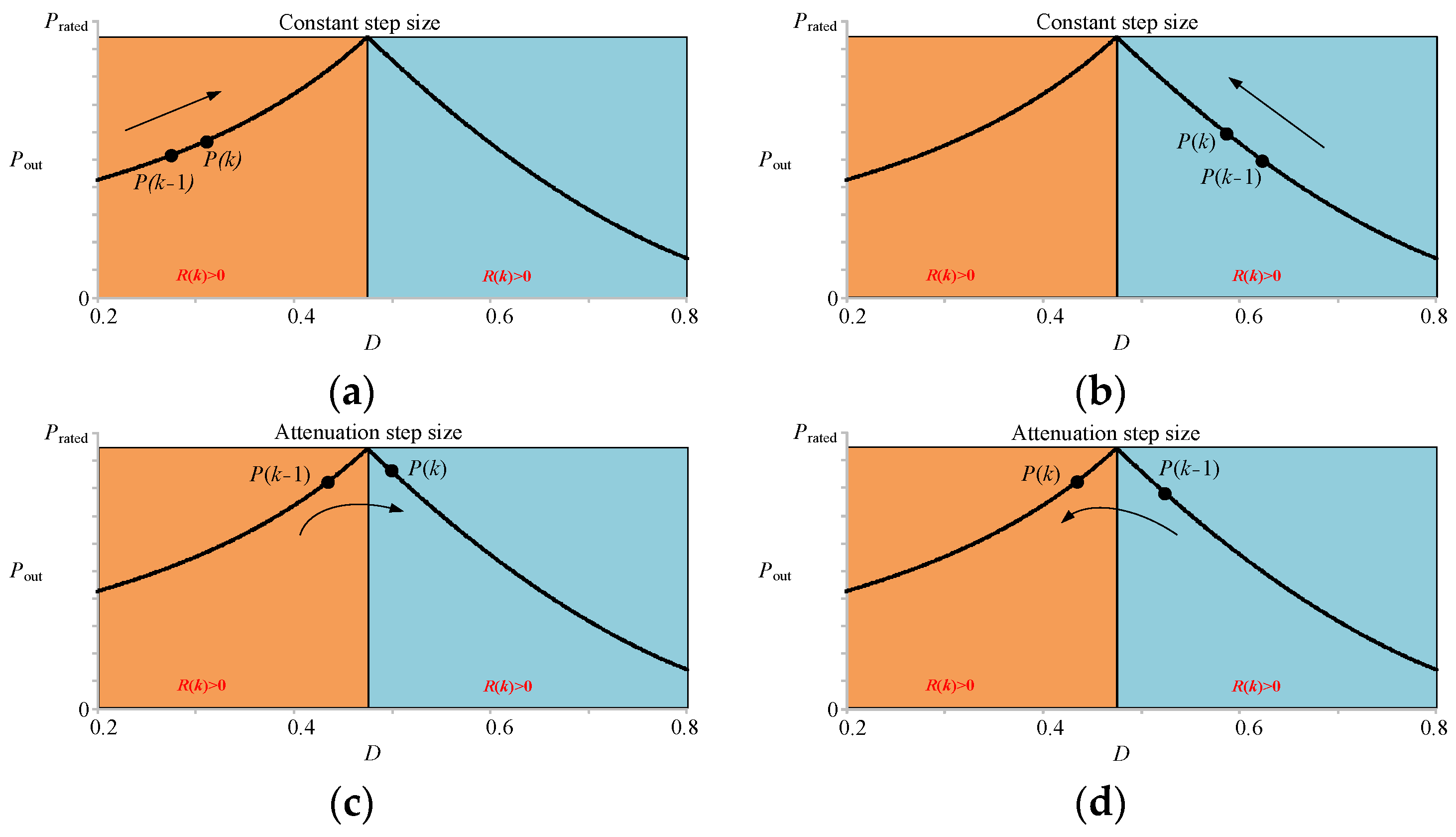
Figure 4. Similarly to the output power profile with the equivalent load, the output power increases at first and then decreases with respect to the duty ratio, and the maximum output power is reached when (7) holds. The output power profile is similar to a hill, and when climbing along one side of the “hill”, the step size should remain large; while approaching the “summit”, the step size should be reduced to improve the accuracy of the results. In order to clarify the searching direction,
R(
k) is defined as the slope of the curve at the point of the
kth step as follows:
where
R(
k) and
R(
k − 1) are the slopes of the output power profile in the
kth and (
k − 1)th searching steps, respectively.
As shown in
Figure 4a, if
R(
k) > 0 and
R(
k − 1) > 0, the search proceeds on the left side of the “hill”, and the step size of the MPPT algorithm should remain large to improve the tracking speed of the system. If
R(
k) < 0 and
R(
k − 1) < 0, a large step size is still needed for the searching process on the right side of the “hill”. However, if the searching process approaches the “summit” of the “hill”, the direction should be reversed, and the step size should be reduced to improve the accuracy of the MPPT algorithm. Further, the conditions of
R(
k) < 0 and
R(
k − 1) > 0 shown in
Figure 4c indicate that the searching process is over the “summit”, and climbing from the right with a shortened step size should be executed for the next step. On the contrary, as shown in
Figure 4d, if
R(
k) > 0 and
R(
k − 1) < 0, the searching process of the next step should be on the left side of the “hill”, and the step size should be shortened.
To sum up, for situations in
Figure 4c,d, the following relationship is satisfied:
To reduce the searching step size, the following is true:
where
C is the decay coefficient of the step size.
In this paper, according to the Hua Loo-Keng optimization method,
C was set to 0.382 (the symmetric value of the golden ratio of 0.618) to find the maximum power operating point in as few steps as possible. Therefore, for the
nth optimization step, the following equation is true:
Therefore, the system should converge to a small step size approaching 0 and oscillate near the maximum power point.
According to (30), the maximum power point of the system is reached with infinite optimization steps. However, in practice, the step size ΔDstep should be set to a relatively small value to make not only the controller sensitive to the change of the mutual inductance, but also the system able to approach the maximum power point with sufficient time.
4.2. Responding Quickly to the Variation of the Mutual Inductance
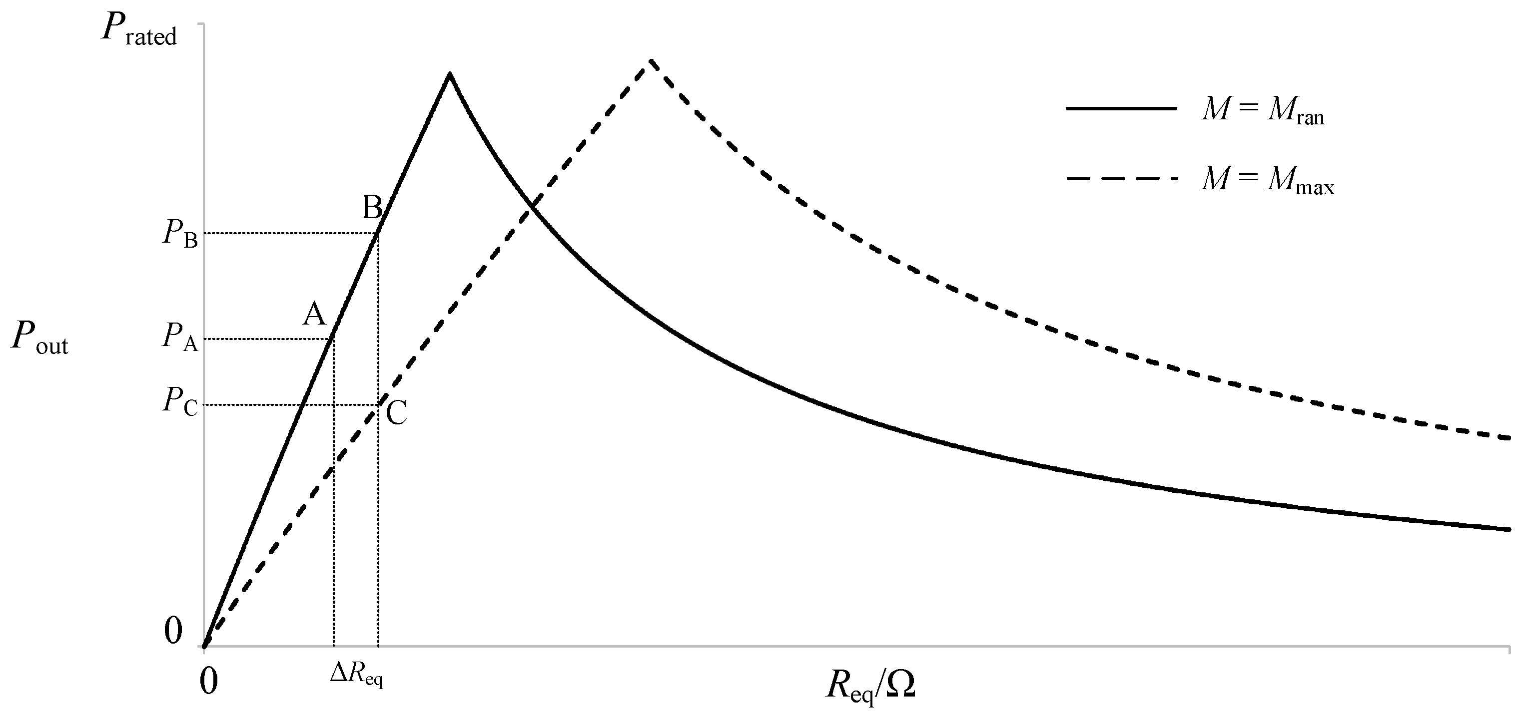
The maximum power point of the system can be reached quickly by applying the aforementioned design strategy. However, once the mutual inductance changes beyond a certain range, the waveform of the output power characteristics change accordingly, thus the results of the searching process are affected, as shown in
Figure 5.
Figure 5 shows the variation of the output power with the equivalent load under the mutual inductance values
Mran and
Mmax, respectively. When the system operates at point A with the mutual inductance
M =
Mran, the output power
Pout is
PA. The controller adjusts the duty ratio
D of the DC–DC converter with a step change Δ
Dstep, so that the equivalent load changes with Δ
Req. If the mutual inductance
Mran remains constant, the operating point moves from Point A to Point B, and the output power
Pout is
PB. However, during the MPPT searching process, if the mutual inductance changes from
Mran to
Mmax due to the change of the coupling conditions, the operating point is located at Point C with Δ
Req, and the output power
Pout is
PC. Note that
PC is smaller than
PA, which leads to searching process moving towards the reverse direction. The chaos causes a delay for the controller to find the correct direction. In addition, much more time is needed to locate the maximum power point.
In order to overcome this issue, the controller should respond quickly to the variation of the mutual inductance. In this paper, the searching process of the maximum power point should be terminated immediately if the following is true:
where
Pout(
k − 1) is the output power of the (
k − 1)th step,
Pout(
k) is the output power of the
kth step, and
ε is a positive constant, which should be selected to identify whether the change of power is caused by the step size or the variation of the mutual inductance.
Once (31) holds, the controller calculates the mutual inductance again, then initializes the step size and searches for the maximum power point with the new mutual inductance. Therefore, the searching time of the maximum power point is reduced and the dynamic performance of the WPT system is improved.
5. Simulation Verification
In order to verify the identification method and the control strategy proposed in this paper, the combination of high-power simulation and low-power experimental verification was adopted. The simulation was realized using the MATLAB/Sumilink software 2020b. The system’s control block diagram is shown in
Figure 6. The simulation parameters are shown in
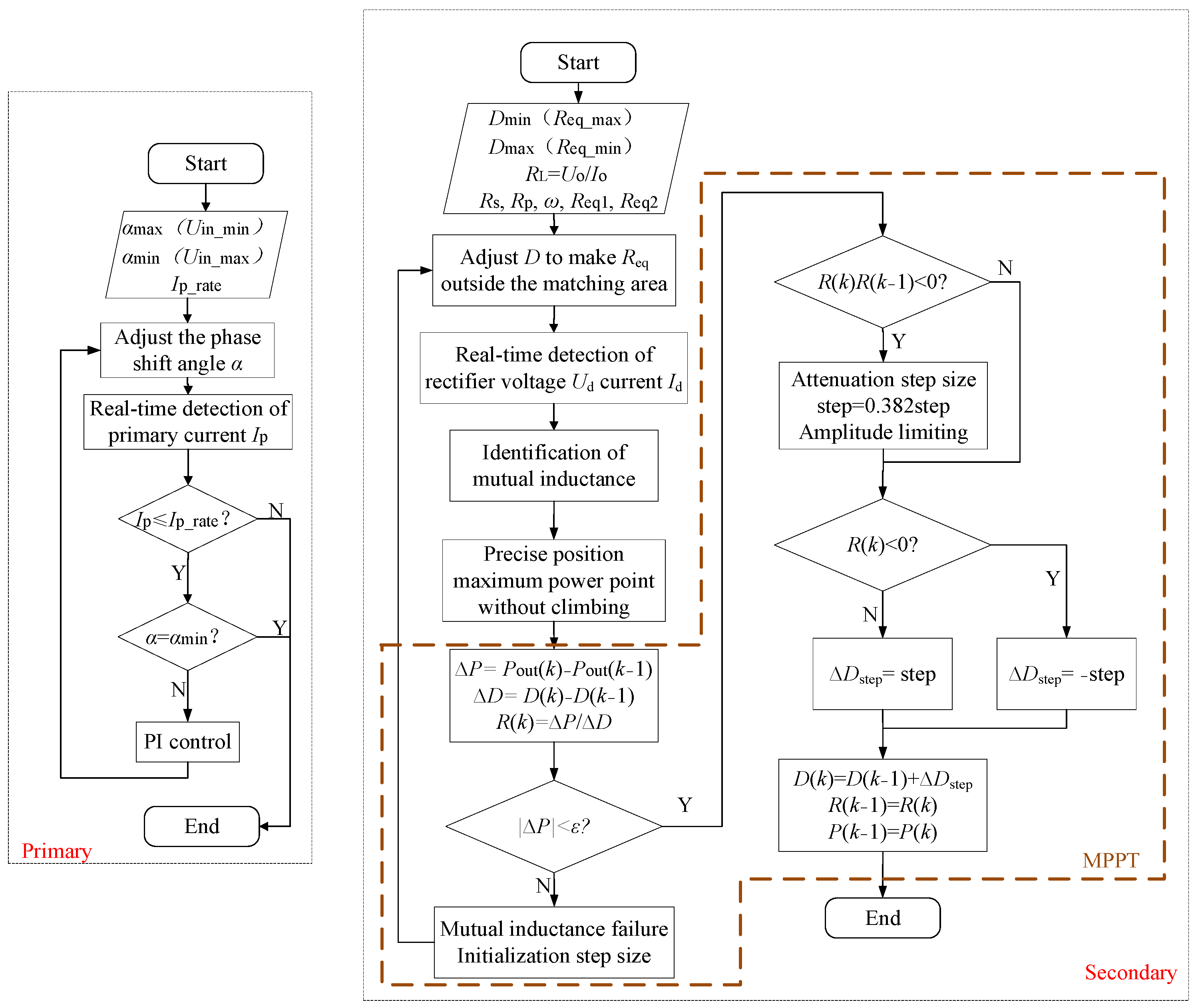
Table 3. The control flow chart of the primary and secondary sides is shown in
Figure 7.
For the purpose of high-output power and stability of the system on the primary side, a PI controller was selected to follow Ipmax and reach the maximum output power point quickly.
For the secondary side, in order to achieve the MPPT of the system, the duty ratio of the DC–DC converter was controlled to make the equivalent load match the mutual inductance, as in (7). Firstly, according to the mutual inductance identification method above, the mutual inductance of the system was obtained at the beginning of the control procedure. Further, according to the identified results, the equivalent load Req was calculated using Equation (7), and the duty ratio D was adjusted to locate the MPPT. Due to the deviation between the identified and real results, the located maximum output power point was also different from the real one. Therefore, the proposed searching process with a variable step size was conducted to locate the maximum output power point more accurately. Further, if the power value measured in the (k − 1)th step is significantly different from that in the kth step, as in (28), caused by the variation of the mutual inductance, the process of searching for the maximum power point with a variable step size should be terminated, and then the mutual inductance needs to be re-identified, and the step size should be initialized.
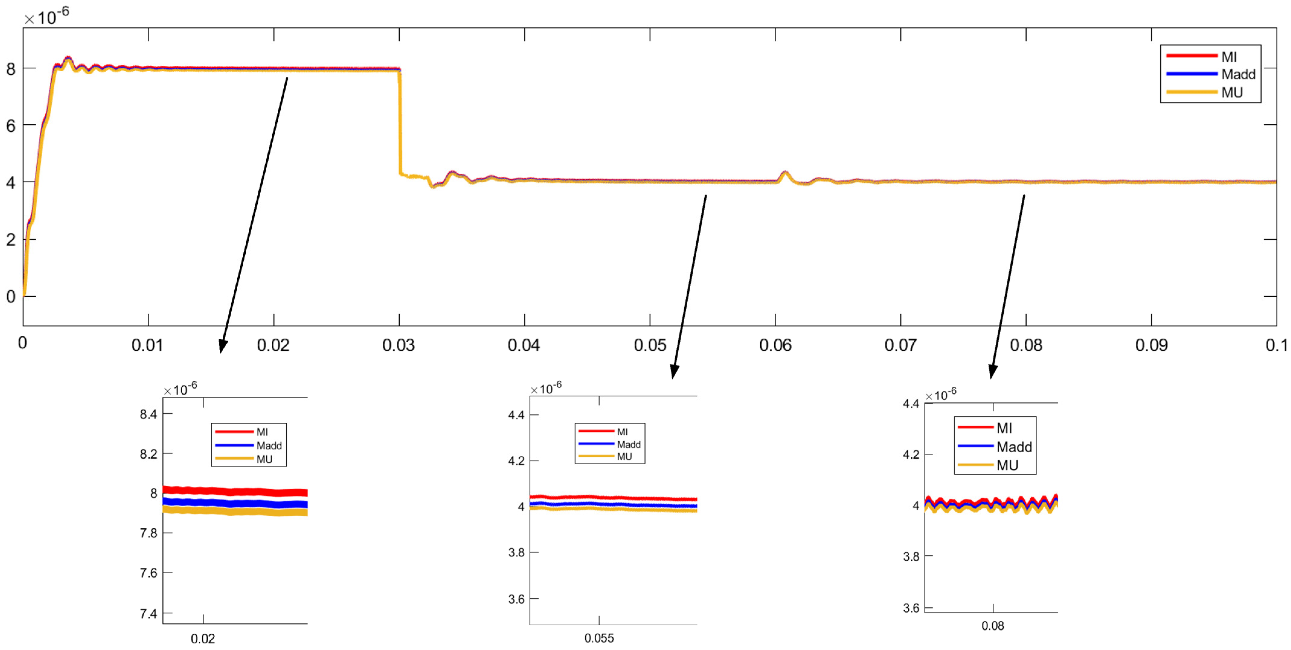
To verify the accuracy of the proposed mutual inductance identification method, three identification methods were compared, including the voltage, the current and the proposed weight identification methods, and the simulation results are shown in
Figure 8. The initial value of the load resistance and the mutual inductance were 5 Ω and 8 μH, respectively. At 0.03 s, the mutual inductance changed from 8 μH to 4 μH, and the load resistance remained unchanged. Then, at 0.06 s, the load resistance changed from 5 Ω to 10 Ω with the unchanged mutual inductance of 4 μH.
When the mutual inductance and the load resistance varied at 0.03 s and 0.06 s, respectively, the input power changed accordingly. To keep the current of the primary side constant, the voltage of the primary side needed to be regulated, which led to the fluctuation of the identified mutual inductance. It can be seen that the settling time was less than 0.01 s, which indicates that the system responded quickly to the variation of the coupling condition and the load. The step cycle is the operating interval of two steps, and it was set to 0.01 s.
Compared to the real value, the mutual inductance values identified using the
Us,
Is, and the proposed sensitivity weight methods and identification errors are summarized in
Table 4. It can be seen from the simulation results that the identification errors obtained by the three identification methods were small, and the highest accuracy was obtained using the proposed sensitivity identification method.
Then, the proposed variable step-size MPPT control strategy based on the mutual inductance identification was verified compared with the traditional P&O MPPT control strategy. The mutual inductance
M was set to 8 μH. The comparison of the two control strategies is shown in
Figure 9. According to the simulation results, the same result was achieved by the two control strategies. However, the hill-climbing search was needed for the traditional P&O MPPT strategy. Therefore, the initial searching step size needed to be large, and more time was required for the controller to locate the maximum power point. Significant overshoot and apparent fluctuation occurred, and several cycles were needed to locate the maximum power point. The mutual inductance was identified at the beginning of the proposed variable step-size MPPT control procedure, and the operating point could be located accurately in the first step cycle.
Therefore, without the hill-climbing searching process, the maximum power point was located quickly, and thus the initial step size was quite small. As a result, the fast location and accuracy tracking of the maximum power point performance was well-demonstrated in the WPT system with the proposed control strategy.
6. Experiment Verification
Experimental verification of the merits of the proposed control strategy is provided in this section. A 1 kW experimental platform is shown in
Figure 10. To meet the requirements of precisely controlling the WPT system with the operating frequency of 30 kHz, TMS320F28335 DSP was taken as the controller to realize the sampling voltage and current, regulating the PWM signal and other functions. To meet the requirement of the WPT system power level and operating frequency, the IPP051N15N5 MOSFET (Infineon, Neubiberg, Germany) was selected as the switches for both the inverter and the DC–DC converter. A diode bridge rectifier on the secondary side was built with a Schottky diode (VISHAY V40150C). Each pair of power devices was connected in parallel to increase the current capacity. Voltage sampling used a differential amplifier circuit to reduce the detection voltage in equal proportions and connect to the AD input port of the DSP. Current sensor LEM HO 60-P could collect the current in the range of ±150 A and the output of 0–5 V. The current value collected by the current sensor was transformed and adjusted before being sent to the DSP for control. Forty points were sampled in each operating frequency period, and the average of the maximum and absolute minimum values was taken as the current amplitude to calculate the effective value of the current. Thirty effective values could be obtained in 30 cycles, and the average of 30 effective values was taken as the control variable.
Experiments were carried out under different air gaps to verify the power efficiency optimization performance. The experimental results of the system power efficiency under different air gaps are summarized in the
Table 5, where
M is the mutual inductance obtained by online identification.
Based on the experimental results, the longitudinal comparison shows that the output power and the transmission efficiency gradually decreased when the air gap increased and the coupling mutual inductance decreased, which is consistent with the theoretical analysis of the circuit. For transverse comparison, under the same air gaps and mutual inductance, the simulation results were basically consistent with the theoretical values, and the errors were within 0.5%. The simulation state was close to ideal, and the effect was good. As for the experimental results, when the coil’s mutual inductance changed with the adjustment of the air gap during the experiment, the self-inductance also changed slightly, so the transmitter and receiver ends were not perfectly resonant, which led to the increase in the reactive power of the system, and the experimental results were lower than the simulation results and the theoretical values. However, the relative error was basically kept within 13%, and the transmission power was basically rated, and the efficiency was basically kept above 80%, which is within the acceptable range.
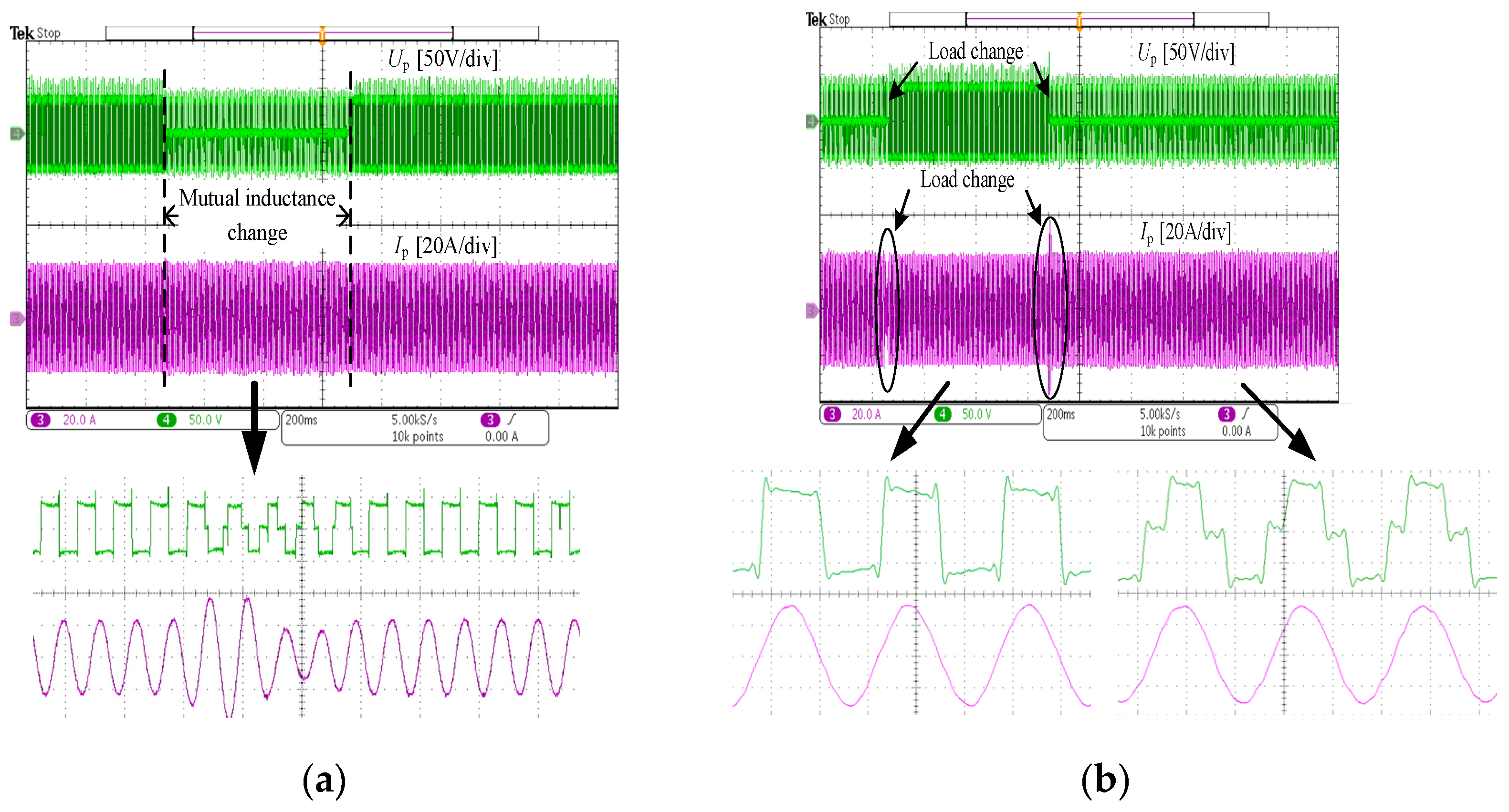
Firstly, the dynamic performance of the system was verified. The experimental results under the condition of the changing mutual inductance and load are shown in
Figure 11. During the experiment, mutual inductance was changed by adjusting the coil air gap, as shown in
Figure 11a. The process of the mutual inductance change was relatively smooth. During the 600 ms change process, the system realized a rapid response and maintained the current
Ip stability. By adjusting the electronic load to achieve a sudden change in the load, as shown in
Figure 11b, the system achieved a rapid adjustment within 20 ms to ensure that the current returned to the rated state.
According to the results, it performed well in responding to fast dynamic changes of the mutual inductance and the load and adjusting the phase shift angle to keep the primary current constant.
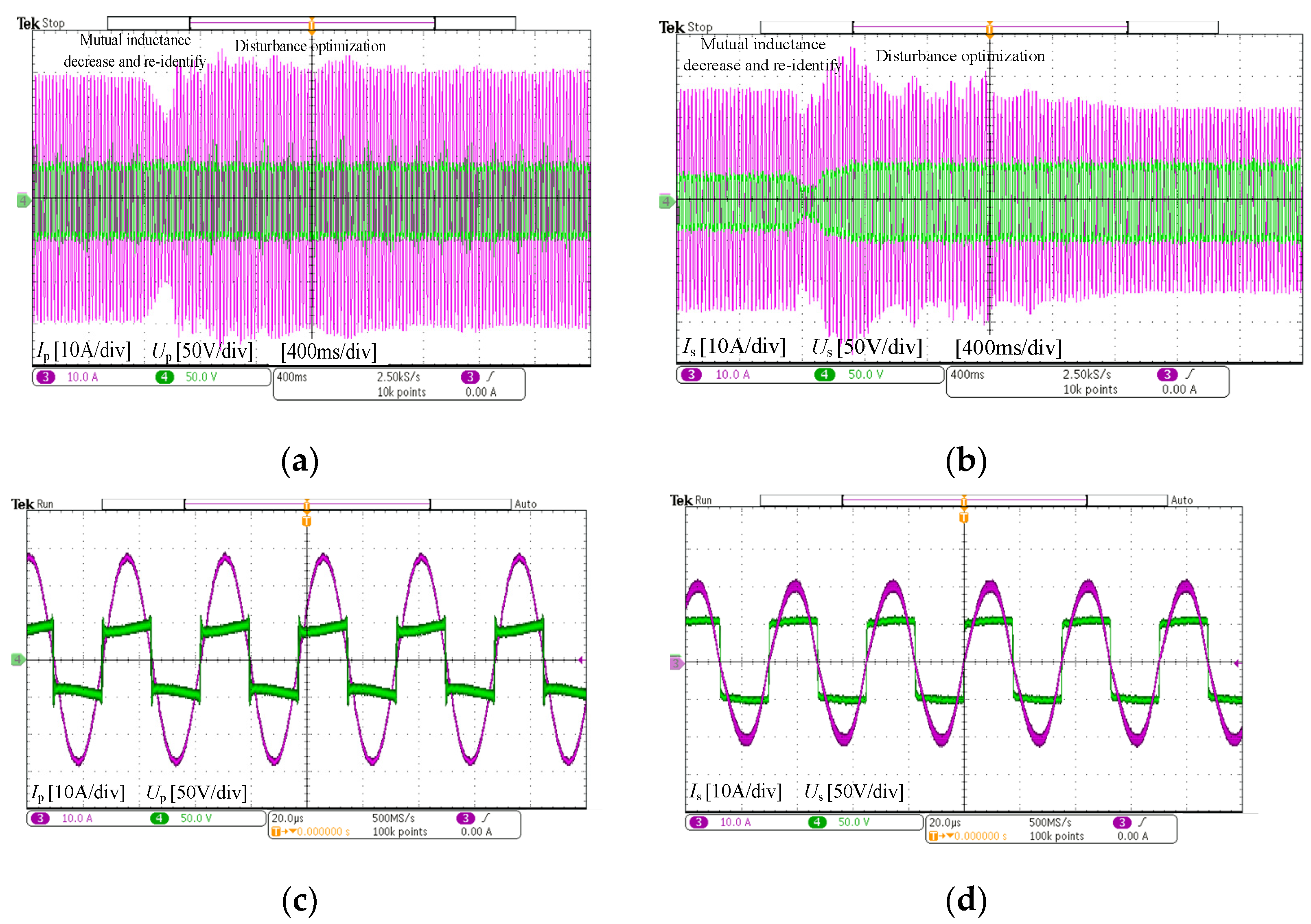
Then, the experimental verification based on the proposed variable step-size MPPT control strategy was carried out under the condition of the mutual inductance value increasing and decreasing abruptly to verify the dynamic performance and output capacity of the system. Because the mutual inductance cannot change abruptly, the step cycle of the experiment was set to 100 ms.
Figure 12 and
Figure 13 show the experimental results of the increasing and decreasing mutual inductance, respectively. It can be seen that, within one step cycle, the hill-climbing searching process was terminated, the mutual inductance was re-identified, and the step size was reset once the mutual inductance changed. Then, the variable step-size hill-climbing searching process was carried out near the optimal operating point to maximize the power output capacity of the system.
On the premise that the control methods shown in
Figure 12 and
Figure 13 can realize a rapid response to the mutual inductance changes, the output power and the transmission efficiency of the stabilized system are summarized in
Table 6, which can be combined with
Table 4. Although the output power decreased with the mutual inductance, the power transfer level did not degrade. As a result, the advantages of the SS compensation topology in transferring high power under weak coupling conditions were fully realized, and the disadvantages of poor dynamic performance were significantly improved by the proposed control strategy.
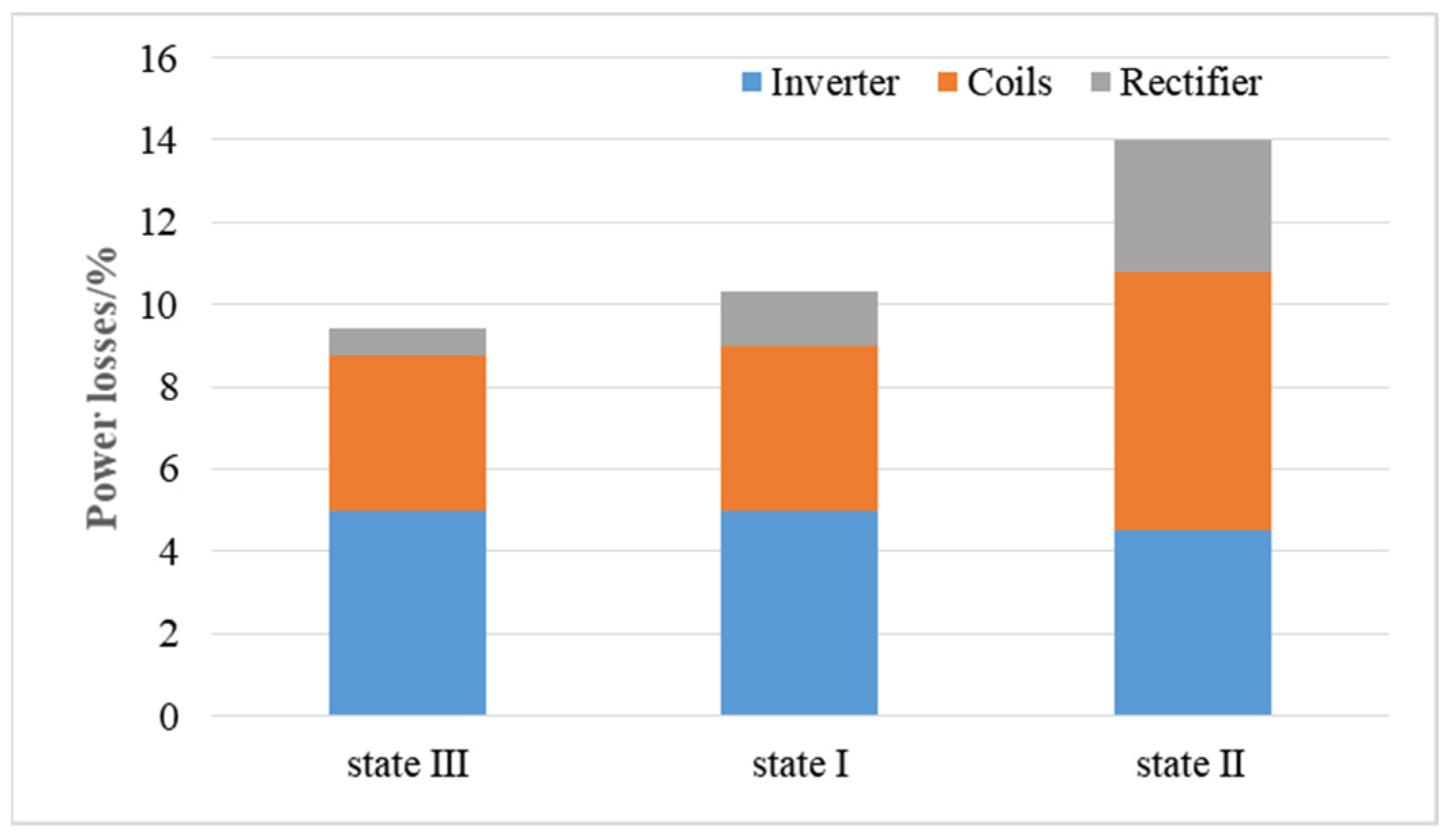
By measuring the power of each circuit, the power loss distribution could be obtained as
Figure 14.
7. Conclusions
This paper presents an improved variable step-size MPPT control strategy for SS compensation WPT systems. Compared with the conventional P&O control, it can achieve a faster response and more accurate tracking, which is very important for the WPT for rail transit. The proposed control strategy has three characteristics:
- (1)
No communication between the transmitter and the receiver. Lack of communication between the two sides is achieved by the mutual inductance identification based on parameter sensitivity. The system requires no additional communication equipment, which can save space and costs and effectively avoid the hidden danger of information delay and errors.
- (2)
Steady-state tracking accuracy. Based on the results of the mutual inductance identification, the optimal operation point can be precisely determined. Then, the steady-state tracking accuracy of the system is improved by the exponential attenuation of the disturbance step.
- (3)
Quick response to changes in the mutual inductance.
In case of an apparent change in the mutual inductance, the system terminates the hill-climbing searching process, relocates the operating point, and initializes the step size to improve the dynamic performance of the system.
To sum up, lack of communication between the transmitter and the receiver, fast and accurate tracking of the maximum power output points, and quick response to disturbance can be realized. The advantages of SS compensation in transferring high-level output power under the low mutual inductance are fully utilized, and the dynamic performance of the system is distinctly improved. The experimental results show that the system has a fast response to variation, and can achieve accurate location and tracking of the maximum power output point within one step cycle to ensure the maximum output level of the system.
The method is designed for WPT systems used in trams, because the rail is limited to only one degree of freedom in the horizontal direction and the change of the mutual inductance in the dynamic process is relatively stable and can be roughly limited to a range. However, for electric vehicles or other equipment, the horizontal offset freedom is large, and the change range of the mutual inductance is also large, but if the mutual inductance is clearly within a fixed range, this algorithm can be used.
At the same time, the current research has some limitations. First, the advantages of higher-order topologies such as LCC are becoming more and more obvious, and they have a better performance than basic topologies. Future research should make more attempts for higher-order topologies. Secondly, the control strategy in this paper was based on the default primary side voltage retention rating, but in the actual application process, voltage fluctuations have a large impact on the stability of the system. Further, during the actual operation of the system, the fluctuation of the air gap causes a change of the coil’s self-inductance, resulting in an incomplete resonance state of the system, which has a great impact on the transmission efficiency and device stress. In the future, the dynamic induction and adjustment of the frequency are also issues that need to be considered. Finally, the application of radio energy transmission systems in electric vehicles and other transportation fields has become an inevitable trend, and integration with the existing infrastructure and reduction of the difficulty of large-scale application are the problems that the wireless charging industry needs to consider.


