1. Introduction
QKD protocols are central to quantum cryptography in the quantum era, harnessing the principles of quantum mechanics to establish secure communication channels. These protocols facilitate secure two-party communication by exploiting quantum phenomena to detect eavesdropping attempts, thereby ensuring information-theoretic security. The BB84 protocol [
1,
2,
3,
4], one of the most recognized schemes, serves as a foundation for numerous subsequent protocols designed to enhance security and efficiency.
The B92 [
5,
6] protocol simplifies key exchange by using only two non-orthogonal quantum states, but its practical implementation often requires additional error correction due to noise and errors in detection, which can impact the key exchange process. The six-state protocol (SSP) [
7,
8] extends BB84 by employing three mutually unbiased bases, increasing eavesdropper detection at the cost of greater resource consumption. The differential phase shift (DPS) protocol [
9,
10] leverages coherent pulse sequences, improving robustness against photon-number splitting (PNS) attacks and facilitating integration with fiber-based networks.
To optimize QKD for long distances, the Coherent One-Way (COW) protocol [
11,
12] uses coherent states with temporal modes, maintaining security through coherence monitoring. The SARG04 protocol [
13,
14], a BB84 variant, enhances resilience against PNS attacks by modifying basis selection. These protocols underscore the theoretical security of QKD while adapting to practical implementation constraints.
With the expansion of quantum networks, scalable QKD solutions are essential. The trusted-node architecture [
15,
16] extends QKD over long distances by relaying quantum signals but introduces vulnerabilities if nodes are compromised. To mitigate this, MDI-QKD [
17,
18] eliminates attacks on photon detectors, enhancing security despite requiring complex quantum relay stations.
The TF-QKD protocol [
19,
20] addresses signal attenuation by exploiting quantum interference between distant sources, significantly improving long-distance communication. However, its implementation demands precise control of quantum states and advanced optical infrastructure. Despite these advancements, challenges in scalability, security, and technological feasibility persist. Future research must refine protocols like MDI-QKD and TF-QKD to ensure the reliable and widespread adoption of QKD in quantum networks.
In this work, we introduce the Loop-Back QKD protocol, a novel scheme specifically designed for secure key distribution in multiuser ring topologies. Unlike trusted-node QKD, it preserves quantum integrity throughout the transmission process by ensuring that secret keys are never processed by intermediate nodes. Additionally, it differs from MDI-QKD and TF-QKD as it does not rely on entanglement or complex quantum measurement setups, making it well suited for near-term deployment in local and metropolitan-scale quantum networks. Furthermore, Loop-Back QKD does not require the public revealing of the measurement bases, significantly enhancing its security. The concept of not requiring basis disclosure was introduced earlier by the same authors in [
21,
22]. The proposed Loop-Back QKD protocol leverages symmetry principles in its bidirectional transmission and structured turn-based mechanism, ensuring balanced key distribution across network nodes. This inherent symmetry enhances the protocol’s scalability and robustness against adversarial attacks, making it well suited for secure multiuser quantum networks.
Loop-Back QKD, operating in a ring topology, supports an arbitrary number of participants by assigning sequential transmission turns and allowing each node to randomly select the pulse direction. This structure not only ensures scalability but also enhances security against intercept–resend (IR) attacks, a practical form of MitM attack. Furthermore, by leveraging a multi-pulse transmission scheme, the protocol effectively reduces the QBER, increasing robustness against adversarial interference.
The remainder of this paper is structured as follows.
Section 2 presents the Loop-Back QKD protocol in a linear topology, covering its Single-Pulse, Hybrid Loop-Back-BB84, and Multi-Pulse variants, along with a comparative analysis of single-pulse and double-pulse configurations.
Section 3 extends the protocol to multiuser scenarios, describing its implementation in a ring topology.
Section 4 explores scalability considerations and the optical hardware requirements for practical deployment. Finally,
Section 5 summarizes our findings and outlines directions for future research.
2. Loop-Back QKD in a Linear Topology
The Loop-Back QKD protocol provides a versatile framework for quantum key distribution, allowing for different implementations depending on security requirements and network constraints. While the standard protocol follows a direct interaction between Alice and Bob, its design naturally extends to multiuser environments, supporting various network architectures.
This section introduces the Loop-Back QKD protocol in a linear topology, detailing both its standalone implementation and its hybrid integration with BB84. The following section explores a ring topology optimized for multi-node quantum networks. Each approach strikes a balance between efficiency, security, and feasibility, allowing the protocol to adapt to various operational environments. A comparative analysis is provided to emphasize the strengths and trade-offs of each configuration.
2.1. Single-Pulse Loop-Back QKD
In the IR attack, Eve deploys a measurement device similar to Bob’s to measure the quantum states sent by Alice over the channel. After obtaining the measurement results, Eve generates a pulse and sends it to Bob’s station. This type of attack is referred to as a MitM attack.
The Loop-Back QKD protocol was specifically designed to detect MitM attacks. It builds on the BB84 protocol, where Alice takes on the role of Bob, thereby eliminating the need to reveal the measurement bases. Specifically, while Bob does not measure the quantum state received from Alice, he polarizes it in one of the bases and then returns it to Alice. In this context, polarizing refers to preparing the quantum state using optical polarizers aligned with a specific basis , rather than applying a quantum gate or performing a measurement. This approach ensures that the state remains within a well-defined basis, analogous to how BB84 encodes information using polarizers.
Upon receiving the returned state, Alice measures it in the same basis she originally used to send the state. If the measurement result corresponds to a state orthogonal to the one sent, Alice can deduce the basis used by Bob. Alice and Bob use the identification of bases to encode the shared bits: cases where Bob selects the Z-basis represent 0, while those where he chooses the X-basis represent 1.
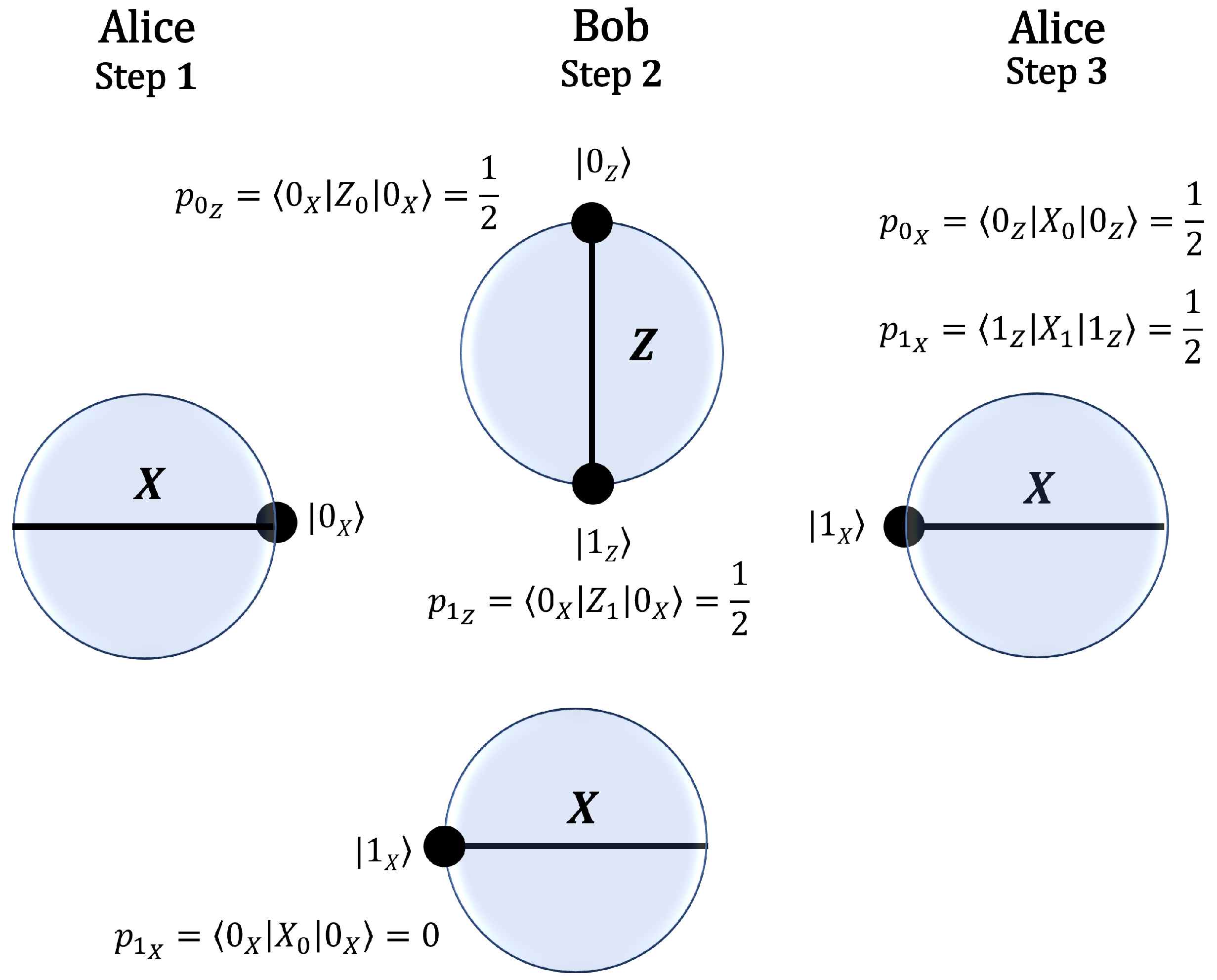
In the protocol, Alice prepares and sends a quantum state
to Bob using the
X basis. Bob then randomly selects a measurement basis, either
X or
Z, and applies the corresponding polarization.
Figure 1 illustrates in the Bloch sphere, the case where Alice sends
. If Bob measures in the
Z basis, the resulting state is an equal superposition of
and
, leading to a probability of 0.5 for Alice to obtain the orthogonal state
upon measuring in the
X basis. If Bob measures in the
X basis, the probability of obtaining
is zero. Since Alice performs her measurement in the same basis she used to prepare
, whenever she obtains the orthogonal state
, she can conclusively infer Bob’s choice of basis.
Conversely,
Figure 2 depicts, in the Bloch sphere, the scenario where Alice sends
. If Bob measures in the
X basis, the probability of obtaining
is unity. Alice then measures in the
X basis, and, if she obtains
, this outcome could have originated from Bob measuring in either the
X or the
Z basis. Thus, in this case, Alice cannot infer Bob’s choice of basis.
In the previous explanation, we adopted a quantum mechanical approach to describe state transformations and measurement probabilities. However, in the following sections, we will minimize the use of this formalism to facilitate the exposition of QKD protocols while preserving the essential quantum principles.
The probabilities associated with the
state are provided in
Table 1, which allows us to deduce that the protocol’s efficiency (
) in an ideal channel reaches 25%.
To provide a clearer understanding of the notation used in this work, we define the symbols in
Table 2.
The protocol can be summarized in the following steps:
Alice prepares a quantum state in either the X or Z basis, such that , and sends to Bob.
Bob, without measuring the state, applies a polarization operation using either the X or Z basis and returns the state to Alice.
Alice measures the returned state using the same basis in which she originally prepared it.
If the state remains unchanged, Alice cannot determine Bob’s basis choice. However, if the measurement result is orthogonal to the originally prepared state (), this indicates that Bob used a basis different from Alice’s preparation basis, allowing her to infer Bob’s choice.
Alice and Bob use the basis identification process to generate a shared secret key.
2.2. Hybrid Loop-Back-BB84 QKD
The Loop-Back protocol can be integrated with BB84 to create a hybrid configuration that enhances security against MitM. Under this protocol, Bob may modify the state returned to Alice according to the following schemes: (1) polarize the state in one of the bases , (2) leave the state unpolarized (return it as received), or (3) measure it in one of the bases . In essence, this setup combines a traditional BB84 protocol with an inverted protocol executed by Alice. Finally, the states returned unaltered by Bob to Alice allow her to verify the integrity of the quantum channel.
Alice and Bob have synchronized systems and are aware of the quantum channel’s losses and error rate (e). The system requires Alice to use a detection setup identical to Bob’s, and Alice knows the round-trip time of a quantum pulse.
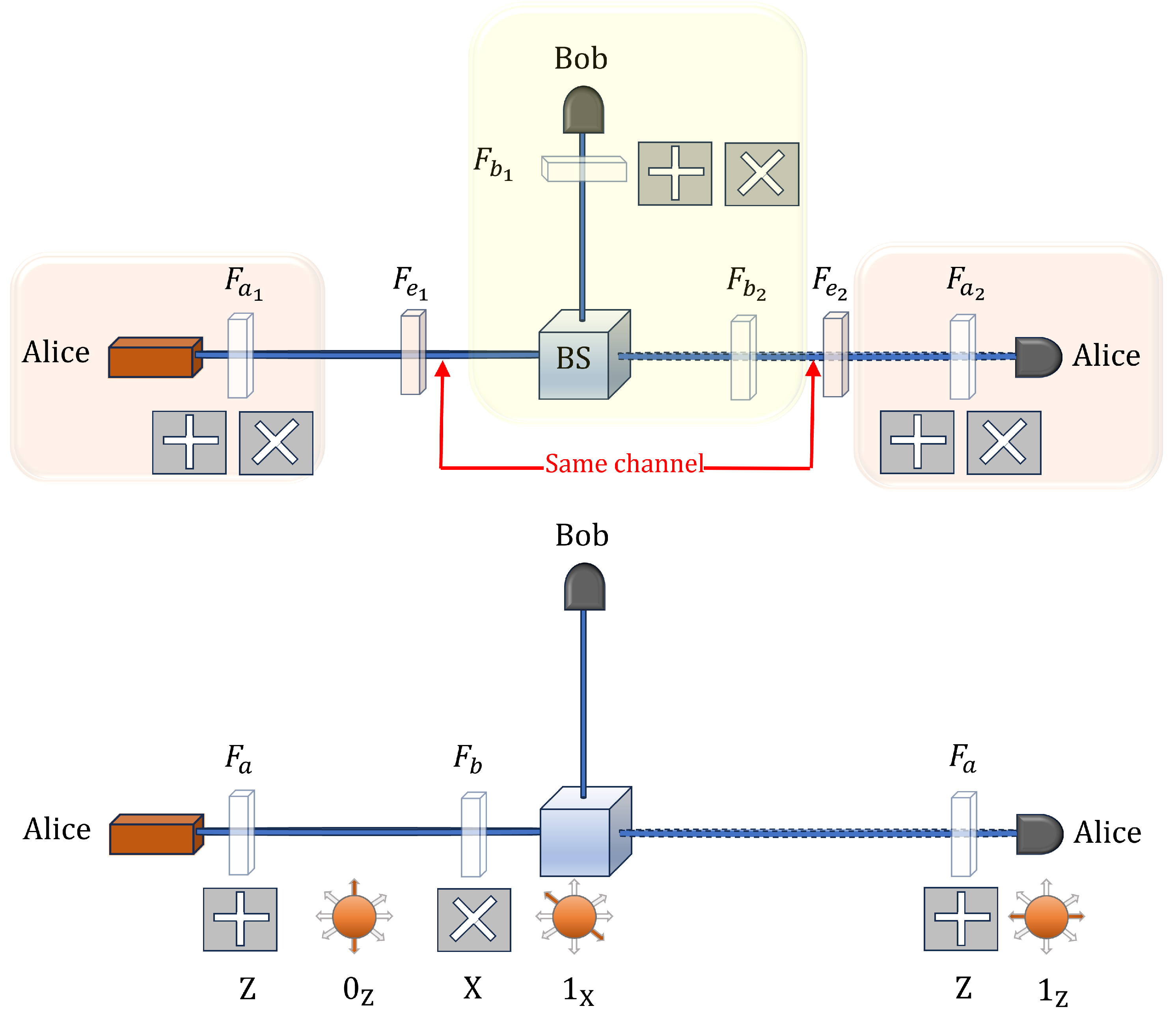
The upper schematic in
Figure 3 shows the optical setup the protocol, where Alice first acts as the transmitter and subsequently as the receiver. The communication occurs via the same optical channel in both directions, as indicated in the figure. The solid line denotes the initial transmission from Alice to Bob, while the faded line represents the return transmission from Bob to Alice at a later stage. Bob performs an intermediate measurement using a randomly selected basis, after which the signal continues to Alice, who also selects a basis for detection.
It is important to highlight that Bob’s polarizers, labeled
and
in the figure, can be reduced to a single polarizer, as illustrated in the lower schematic of
Figure 3. This reduction arises from the fact that Bob either measures the incoming pulse in a chosen basis or polarizes it before retransmission, but he cannot perform both operations simultaneously. Consequently, a single polarizer suffices to fulfill both functions. Similarly, for Alice, the polarizer
is identical to
, as required by the structure of the protocol. This optimization simplifies the optical setup while ensuring the integrity of the quantum state transmission is preserved.
During a MitM attack, Eve installs two devices: one that measures the state sent by Alice and allows her to resend a pulse to Bob with the polarization of the result obtained from her measurement, and another that measures the state returned by Bob, which Eve then forwards to Alice.
Protocol Description
Alice and Bob follow these steps:
Alice randomly selects a basis and prepares a state , such that , and sends to Bob.
Bob applies one of three possible operations:
- (1)
Polarize and resend: Bob selects a basis , polarizes the state accordingly, and sends it back to Alice.
- (2)
Forward unchanged: Bob does not modify the state and simply returns it as received.
- (3)
Measure the state: Bob measures in a randomly chosen basis (X or Z), collapsing the quantum information.
Alice measures the returned state. If Bob did not discard the state in case (3), Alice measures it using her original basis .
Bob announces his operations. Over a classical channel, Bob reveals which of the three operations he applied. If he performed a measurement (as described in operation (3)), he also discloses the basis he used.
Alice classifies the results:
- —
Sifting cases: If Alice’s measurement result is orthogonal to her original state (), she can deduce the basis used by Bob. These cases are used for key generation.
- —
Channel verification cases: If Bob returned the state unchanged, Alice uses these events to monitor the quantum channel’s error rate. Deviations from the expected error rate may indicate the presence of an eavesdropper, serving as the first strategy for attack detection.
Key reconciliation and privacy amplification.
- —
Alice and Bob reconcile their keys using the sifting cases.
- —
They apply error correction and privacy amplification to generate two secure keys: one from the direct transmission () and another from the full round trip ().
- —
The final key is obtained by applying an XOR operation to and to enhance security.
Table 1 presents the probability distribution of the Loop-Back protocol in an ideal quantum channel.
Table 3, on the other hand, illustrates the distribution in the presence of Eve conducting a MitM attack on the quantum channel.
Based on these results, we now describe the second method for detecting the presence of Eve in the quantum channel.
Table 4 presents a comparison of the performance of the BB84 and Loop-Back protocols. The column labeled
is the throughput of the protocol, i.e., the total number of events eligible for distillation. As shown in the BB84 protocol,
remains unchanged before and after the attack. Therefore, it is necessary to sacrifice a portion of the bits to measure the error rate of the protocol. In contrast, the Loop-Back protocol exhibits a 12.5% increase in
, meaning that no bits need to be sacrificed to measure the error rate. Instead, it is sufficient to evaluate
directly for the protocol.
As a third measure to detect the MitM attack, Alice can determine Eve’s presence in the channel because Eve is unable to control the delay caused by the attack. Although may be very small, Eve introduces a constant delay of in the link. If Alice measures the round-trip time of the pulse using a sufficiently accurate clock, she will notice this delay compared to the value set during the initial system calibration, thereby concluding with the presence of Eve.
2.3. Multi-Pulse Loop-Back QKD
This enhanced version of the Loop-Back QKD protocol introduces a double-pulse scheme, which increases security and error tolerance by mitigating quantum bit errors. The general case of n pulses will be addressed in Section Efficiency Trade-Off. However, this improvement comes at the cost of lower efficiency compared to the single-pulse version. Unlike BB84, where key generation relies on basis matching, in this protocol, the key is determined based on Bob’s polarization choices.
A key motivation for using double pulses is the reduction in the effective QBER. In a single-pulse scheme, the probability of an error occurring is given by e, where e represents the intrinsic error rate of the quantum channel. In the double-pulse scheme, a valid key bit is generated only when both received states satisfy the orthogonality condition. If an error occurs in only one of the pulses, the event is classified as ambiguous and discarded.
The basic principle is that Alice transmits two quantum states per round, ensuring that both states are prepared in the same basis, either X or Z. The transmitted pairs are selected from the following sets:
- —
In the Z basis:
- —
In the X basis:
Alice is the only one who knows the basis on which each pair was prepared. Upon reception, Bob independently selects a random basis (X or Z) for the pair, polarizes the states accordingly, and returns them to Alice. An attacker cannot distinguish whether a transmitted pair belongs to the set of parallel states or to the set of orthogonal states .
Moreover, even if partial information about one of the states were extracted, it would not reveal additional information about the other state in the pair. This fundamental quantum property ensures that no meaningful knowledge about the transmitted pairs can be obtained by an eavesdropper.
Alice then measures the received states in the same basis as the original preparation (X or Z). Thus, she only accepts events where the measured pair is orthogonal to the originally sent pair.
The specific steps of the Multi-Pulse Loop-Back QKD protocol are detailed in the following procedure.
State preparation: Alice randomly selects a basis and prepares a pair of quantum states and she sends these states to Bob.
Bob’s polarization: Upon receiving the states, Bob selects a quantum basis to polarize both states:
- —
If , the state remains unchanged.
- —
If , the state is polarized onto the new basis with equal probability ().
Bob then returns the polarized states to Alice.
Alice’s measurement and validation: Alice measures the received states in the original basis
. She accepts only those cases where the measured pair satisfies the orthogonality condition:
Any other outcome is considered ambiguous and discarded.
Classical reconciliation: Alice and Bob communicate over a classical channel to confirm which events were accepted, without revealing their bases or individual state values.
Key assignment: The secret key bits are assigned based on Bob’s polarization choices:
- —
If Bob used the Z basis, the accepted pair represents bit 0.
- —
If Bob used the X basis, the accepted pair represents bit 1.
Table 5 presents the probability distribution for the Loop-Back QKD protocol when Alice sends the state pair (
,
). The table details the basis selection by Bob, the possible polarization outcomes, and the results obtained when Alice performs a
Z-basis measurement.
Only cases where Alice’s measurement results in (, ) are considered successful, as these satisfy the orthogonality condition required for key generation. The probability of success is calculated as , indicating that the acceptance rate in this scheme is lower than in the single-pulse protocol, but with an improved robustness against errors.
Entries where at least one state does not meet the orthogonality condition are marked as ambiguous and discarded, reducing the probability of an erroneous bit being included in the final key. As a result, doubling the number of pulses per round reduces the effective QBER to .
Compared to the single-pulse variant, the double-pulse approach offers the following advantages:
- —
The effective error rate is reduced from e to , significantly minimizing the impact of quantum bit errors on the final key.
- —
The requirement for both states to be orthogonal on Alice’s side enhances resistance to MitM attacks.
- —
Alice can more reliably determine Bob’s basis choices, reducing bit loss due to basis ambiguity.
3. Loop-Back QKD in a Ring Topology
The Loop-Back QKD protocol extends naturally to multiuser scenarios, enabling secure key distribution in a network setting. Unlike conventional QKD protocols designed for point-to-point communication, this approach supports an arbitrary number of users by leveraging a bidirectional optical ring. In each round, a designated node transmits quantum states while the other nodes interact with the pulses according to predefined rules.
At any given time, only one transmission direction is active, randomly determined by the transmitting node to introduce additional security against eavesdropping. Each participating node can perform one of the following actions upon receiving a pulse:
- —
Transmit and Measure: The designated node sends a polarized quantum state into the ring and later measures the pulse after it has either been reflected or has completed a full circuit around the ring if all intermediate nodes act transparently.
- —
Reflect with polarization: Apply a unitary transformation in a randomly chosen basis (X or Z) and return the pulse to the sender.
- —
Forward without polarization: Preserve the pulse’s original state and transmit it unchanged.
A fundamental rule governs the interactions: a node can either reflect the pulse with polarization or forward it without polarization, regardless of the pulse’s incoming direction. Since a pulse propagates through the network, it continues traveling through transparent (forwarding) nodes until it encounters the first reflecting node (see
Figure 4). At this point, the pulse is returned to the sender, allowing them to establish a correlated result with the reflecting node. This structured interaction ensures that sifting occurs efficiently without requiring additional coordination among intermediate nodes.
This mechanism introduces three key security properties. First, since the pulse direction is randomized, an eavesdropper cannot predict or manipulate the transmission path without introducing detectable anomalies. Second, because the reflection process occurs independently of the pulse’s initial direction, an adversary cannot infer information based on routing behavior. Third, the protocol ensures that a number of pulses will always return to their origin after completing the full ring, preserving the same polarization state in which they were originally sent.
To illustrate the protocol’s operation in a networked environment, we consider the simplest multiuser scenario involving three nodes: A, B, C and D. These nodes are interconnected in a ring topology, allowing bidirectional communication as indicated in
Figure 4. In this network, some nodes B, C act as transparent forwarders, while D applies polarization and reflection. The protocol generalizes to any number of users by maintaining the sequential turn system and the rule for polarization and forwarding. The synchronization of turns and direction selection are easily managed through classical communication channels.
Key reconciliation relies on the progressive establishment of correlations between nodes over multiple rounds of transmission. In a given round, A transmits, and the first reflecting node is D, establishing a correlation between them. In subsequent rounds, different nodes take turns transmitting, each time forming a new correlation with the first encountered reflecting node. After a sufficient number of rounds, all nodes in the ring will have established shared correlations. In the ideal case, where no errors occur, these correlations enable the distillation of a global group key among all nodes. Alternatively, depending on network conditions and security requirements, subgroups of nodes (e.g., {A, D}, {A, B, D}, …) can derive independent shared keys based on their accumulated correlations.
A full characterization of the key reconciliation process requires experimental validation or numerical simulation to determine the efficiency of correlation establishment and the impact of quantum channel noise on key rates. Such an analysis would provide insights into the feasibility of group key agreement and the practical security of the multiuser ring-based Loop-Back QKD protocol.
This structure not only ensures scalability but also reinforces security, as the correlations formed naturally limit an adversary’s ability to manipulate the key distribution process without introducing detectable anomalies.
4. Discussion
The design of Loop-Back QKD is primarily motivated by its ability to detect IR attacks, a practical variant of the MitM attack that has been successfully demonstrated in real-world QKD systems [
23]. Unlike other theoretical attack models, the IR attack represents a tangible threat to current QKD implementations, making its detection a critical security requirement. Additionally, the Multi-Pulse Loop-Back QKD variant further strengthens security by reducing the effective QBER, enhancing the protocol’s resilience against adversarial interference.
Another security advantage of Loop-Back QKD is its intrinsic resistance to PNS attacks. This resilience stems from the fact that Bob does not perform measurements on the received quantum states but instead applies polarization before returning them to Alice. Consequently, there is no need for basis revelation, which is a common vulnerability in traditional QKD protocols. In PNS attacks, an eavesdropper (Eve) intercepts and stores a portion of the transmitted quantum states, waiting for basis disclosure to extract information about the final key. However, since Loop-Back QKD does not involve basis revelation, any information obtained by Eve remains useless, effectively neutralizing this type of attack. This design choice reinforces the protocol’s overall security, ensuring that adversarial attempts to extract information through state replication and delayed measurement are fundamentally thwarted.
Beyond security, the protocol’s multiuser design supports scalable key distribution in a ring topology while maintaining an efficient use of the optical channel by enabling bidirectional transmission one direction at a time. Additionally, the random selection of pulse direction and the polarization rules contribute to its robustness against MitM attacks.
A key distinction between Loop-Back QKD and other multiuser quantum communication frameworks lies in its avoidance of trusted-node architectures. Traditional QKD networks often rely on trusted nodes to extend the range of key distribution beyond direct optical transmission limits. In such networks, quantum keys are established between adjacent nodes, but the end-to-end key must be reconstructed through a chain of relays. Each trusted node decrypts and re-encrypts the key, introducing a critical security vulnerability—if a node is compromised, the entire key exchange process is at risk [
24,
25]. In contrast, Loop-Back QKD maintains quantum integrity throughout the network by allowing pulses to propagate unmeasured until they interact with a designated reflecting node. This approach eliminates the need for intermediate nodes to process secret keys, reducing security dependencies and enhancing resilience against adversarial attacks. As a result, Loop-Back QKD is particularly well suited for secure key distribution in local and metropolitan-scale networks, where quantum security must be ensured without relying on trusted infrastructure.
4.1. Security Considerations
A key feature of the Loop-Back QKD protocol is its inherent robustness against depolarization in the quantum channel. Unlike conventional QKD protocols, where quantum bit errors directly impact the key rate, Loop-Back QKD relies solely on the basis used by Bob rather than the exact transmitted state. Since Bob does not measure the incoming quantum state but instead applies a unitary polarization transformation in a randomly chosen basis, the final measurement performed by Alice is only sensitive to the basis alignment, not to the specific state received.
For example, if Alice transmits and Bob chooses the basis X, he applies a polarization operation resulting in . The quantum channel may induce a depolarization, flipping the state to . However, when Alice measures in the original Z basis, she obtains , which still provides unambiguous information about Bob’s basis choice. This property ensures that the protocol remains functional even in the presence of channel-induced depolarization, significantly improving its robustness against noise.
Then, what is the origin of the transmission errors in this protocol? As shown in
Table 6, errors arise from false positives in cases where Bob polarizes the state in the same basis in which it was prepared by Alice, but the channel depolarizes it during its return. This causes Alice to detect it as an orthogonal state, thereby generating an error (assuming ideal detectors).
Depolarization is influenced by the length of the path, which in this protocol is twice the distance of a unidirectional link. However, according to [
26], the QBER increases linearly with distance, while at long distances, fiber losses become the dominant factor contributing to the total QBER.
Since the error-free scenario (when Bob measures in a basis opposite to Alice’s) and the error-prone scenario (when Bob measures in the same basis as Alice) are equally probable, the average channel error rate is expected to be comparable to that of a unidirectional link, as in the BB84 protocol.
However, as depolarization increases, the protocol’s error rate remains below 25%. This behavior arises from the distribution of outcomes, wherein half of the cases remain unaffected by errors, as demonstrated in
Table 6. In other words, even if complete depolarization occurs in all cases where Bob polarizes in the same basis as the state prepared by Alice, the channel error rate would still be bounded at 25%, assuming ideal detector efficiency. An experimental verification of this model will be essential to confirm these limits.
On the other hand, we expect that the absence of measurement basis disclosure in this protocol provides a significant advantage in mitigating more advanced attacks, such as collective and coherent attacks. These attacks typically optimize the measurement of intercepted states by exploiting the publicly disclosed information from Bob [
27].
4.2. Scalability Considerations
A key advantage of the Loop-Back QKD protocol is that its efficiency and security remain unaffected by the number of users in the network. Unlike other multiuser QKD schemes, where additional users introduce complexity in key reconciliation or increase the risk of eavesdropping, Loop-Back QKD maintains a simple and consistent structure:
In any given round of the protocol, only two nodes participate in key establishment: the transmitting node and the first reflecting node encountered along the pulse trajectory. All other nodes act as transparent relays and do not impact the protocol’s efficiency or security.
This property ensures that the overall transmission rate, error resilience, and security mechanisms remain independent of network size, making the protocol inherently scalable. The only practical limitation arises from optical losses due to imperfect transparency in intermediate nodes, which can be mitigated through high-efficiency optical components and careful system calibration.
In an ideal scenario, transparent nodes should allow pulse transmission without introducing attenuation or depolarization. In reality, minor imperfections in optical components, such as beam splitters and fiber couplers, can lead to cumulative losses as the number of intermediate nodes increases. This effect could reduce the key generation rate due to lower detection probabilities at the receiver.
To mitigate these losses, several strategies can be considered. The use of low-attenuation optical fibers and highly efficient optical switches can minimize insertion losses at each node. Additionally, adaptive power balancing techniques may be implemented to compensate for attenuation, ensuring that pulses maintain sufficient intensity upon reaching the reflecting node. While optical amplifiers could theoretically counteract signal loss, their introduction would compromise the quantum security guarantees of the protocol. Thus, optimizing the optical transparency of the network remains the most viable approach for maintaining high efficiency in large-scale deployments.
While it is expected that increasing the number of pulses per round reduces the QBER from e to , this reduction significantly increases the proportion of valid key-generation events. If the effective QBER is sufficiently low, post-processing error correction might become unnecessary or require minimal adjustments. However, in cases where residual errors persist due to optical imperfections or environmental noise, a lightweight reconciliation mechanism such as Cascade could be employed. Unlike forward error-correction schemes that introduce redundant bits, Cascade efficiently detects and corrects errors through interactive parity checks while preserving security. Future work should explore its integration within the multiuser Loop-Back QKD framework, optimizing its performance for large-scale deployments.
Efficiency Trade-Off
Taking
Table 5 as a reference, we calculate the success probability
when Alice sends
n pulses to Bob as described in
Section 2.3.
Table 7 illustrates the probability of a successful measurement outcome in a scenario where Alice sends
n pulses and Bob performs measurements in randomly chosen bases. Since only one of Bob’s basis choices is orthogonal to Alice’s states, its probability is
. Each polarization result that Bob obtains, also occurring with probability
, propagates through Alice’s measurement process, where each measurement outcome maintains the same probability. Given that there are
possible states in Alice’s system and that each step contributes a factor of
, the overall success probability, denoted as
, follows as indicated in Equation (
1).
Beyond the degradation of the success probability, the occurrence of errors in the interpretation of multiple detection events follows a rate of
, as each detection error occurs independently with probability
e, leading to a cumulative probability. By generalizing the secret key rate expression
, originally derived for the BB84 protocol to evaluate individual attacks, we obtain the generalized form given in Equation (
2).
where
H denotes the Shannon entropy, defined as
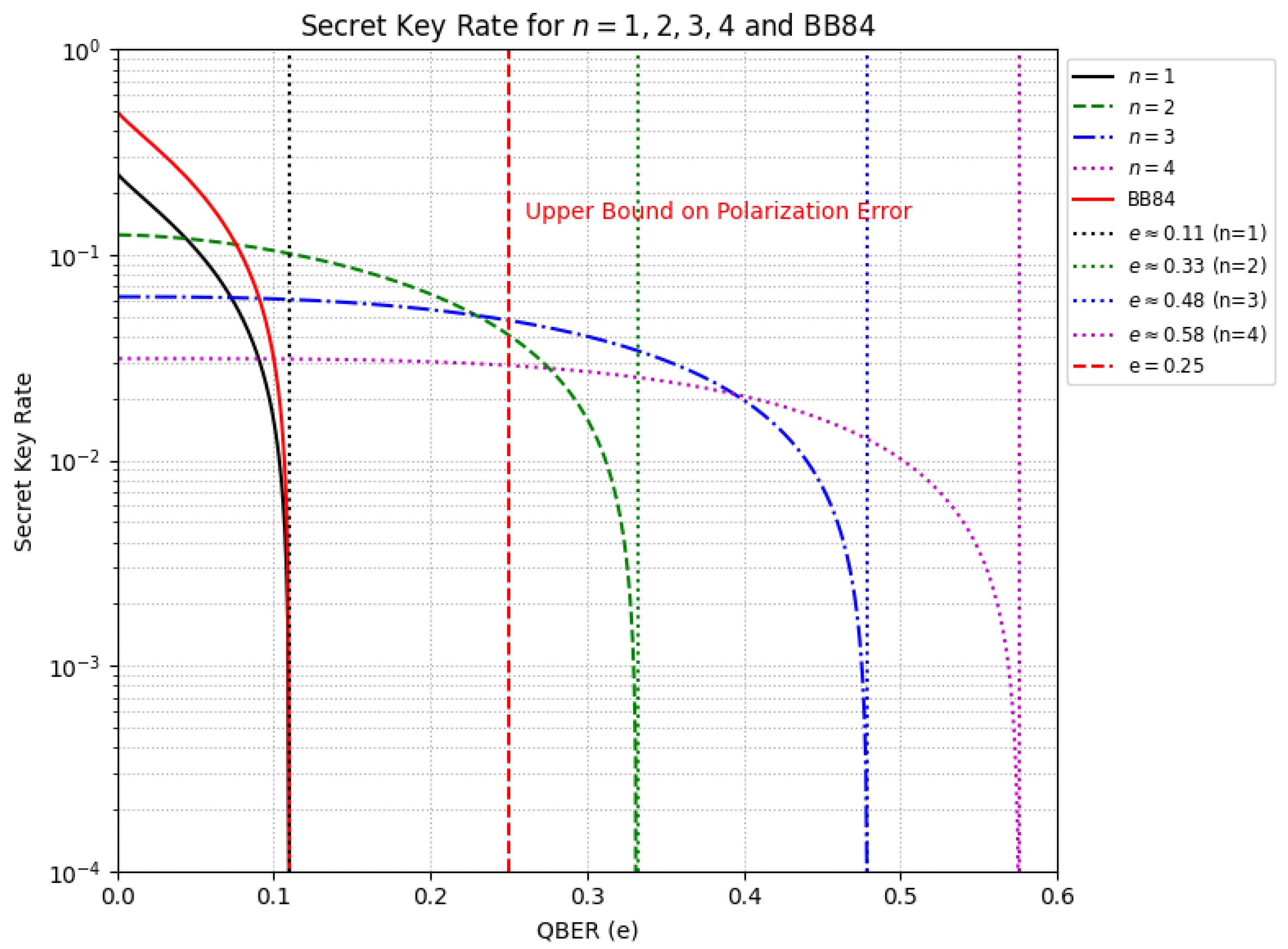
The analysis of
Figure 5 highlights a trade-off between security and efficiency as
n increases. The zero-crossing points mark the threshold beyond which the protocol becomes insecure, as Eve may acquire more information than Alice and Bob. For BB84, this threshold is approximately
. In contrast, for
and 4, it shifts to
and
, respectively, indicating that higher
n allows for greater quantum bit error rates (QBER) before security is compromised. Moreover, as
n increases, the quantum channel error tolerance asymptotically approaches unity, since
when
for
. Provided
, then,
holds while
n increases, so
e must vary accordingly. We obtain
, which leads to the derivation of Equation (
3).
This results in Equation (
4).
Thus, as n grows, e asymptotically approaches 1. However, this advantage comes at the cost of a reduced initial secret key rate, which declines from to . Therefore, while the protocol becomes more resilient to errors, it experiences a lower key generation rate.
The previous results contrast with the reported limits for BB84 (11%), SARG04 (9.68%), and Six-State (12.6%) as presented in [
28]. Future experimental studies may provide further validation of these findings.
4.3. Optical Hardware
Implementing the Loop-Back QKD protocol requires an optical setup capable of supporting bidirectional pulse reflection with polarization transformation. A key challenge arises when a node operates in reflection mode while ensuring that the polarization transformation is consistently applied, regardless of the incoming pulse direction. The protocol’s reliance on multi-pulse interactions introduces the need for precise timing synchronization. Moreover, practical deployment in quantum networks will necessitate compatibility with existing infrastructure, which may impose additional constraints on system design.
The configuration must include a beam splitter to divide incoming pulses into two internal paths, an optical switch to determine whether the node remains transparent or reflects, and a set of wave plate modulators to introduce the polarization transformation. A dielectric mirror or Faraday retroreflector redirects the pulse back toward its source while maintaining the intended polarization. The pulse is reinjected into the fiber by a polarization-sensitive optical coupler to minimize losses and maintain coherence.
In normal operation, the node remains transparent, allowing pulses to traverse uninterrupted. When set to reflection mode, the optical switch directs the pulse to the polarization control unit, where it is routed based on its direction of arrival. The pulse then undergoes transformation using a quarter-wave plate (QWP) or half-wave plate (HWP), followed by reflection and reinsertion into the fiber. To measure the pulse, regardless of whether it arrived through reflection or after completing the full ring, the node leverages a measurement setup that allows it to track the state of the pulse.
The measurement process involves routing the pulse through a polarization analyzer after the polarization transformation. The node can detect the polarization state by comparing it against a known reference basis (either X or Z) using a set of polarization beam splitters (PBS) or other suitable polarization-sensitive detectors. This reference basis corresponds to the basis in which the transmitting node initially polarized the pulse, regardless of the pulse’s initial direction. An alternative approach involves using a Sagnac interferometer, ensuring bidirectional polarization transformation and simultaneous pulse measurement. Additionally, an electro-optic modulator (EOM) can be incorporated into the reflection path for real-time polarization adjustments.
4.4. Comparative Analysis
Table 8 provides a qualitative comparison of different QKD protocols in terms of security model, scalability, complexity, and key rate efficiency. Trusted-Node QKD relies on classical relays, making it highly scalable but vulnerable to node compromises. MDI-QKD and TF-QKD improve security by removing detector vulnerabilities, but they require complex setups, with TF-QKD additionally demanding phase stabilization for long-distance communication. In contrast, Loop-Back QKD offers a multiuser scheme that maintains quantum integrity without trusted nodes, achieving high scalability in local and metropolitan networks while maintaining moderate complexity. This trade-off makes Loop-Back QKD a practical alternative for scalable, secure key distribution in short-to-medium-range quantum networks.
5. Conclusions
We have presented a scalable and secure QKD protocol that originates from a linear topology and extends naturally to multiuser ring configurations. The Loop-Back QKD protocol was first designed for two-party communication, where it provides strong resilience against IR attacks while maintaining high efficiency. The single-pulse variant offers a straightforward and effective key distribution mechanism, whereas the multi-pulse variant enhances security by reducing the effective QBER. Our analysis indicates that Loop-Back QKD with multi-pulses can tolerate higher QBER thresholds than several well-known QKD protocols, including BB84 and SARG04. This suggests that it may offer enhanced robustness in high-noise environments, although further investigation is needed to establish the security bounds. However, this increased tolerance comes at the cost of a reduced key rate efficiency, as the secret key rate scales as , making the protocol less efficient compared to traditional QKD schemes.
Additionally, the hybrid LB-BB84 configuration enhances the detection of MitM attacks by enabling bidirectional key distillation, leveraging the strengths of both protocols to improve security against active adversaries. These linear configurations demonstrate significant security advantages over traditional point-to-point QKD schemes.
Building on this, Loop-Back QKD extends naturally to ring topologies, enabling secure multiuser communication. The sequential turn system ensures that each node participates in a structured manner, optimizing network efficiency while maintaining security. By leveraging random pulse direction, the protocol mitigates MitM attacks and provides robust error correction and key reconciliation.
This makes Loop-Back QKD particularly well suited for secure communication in local quantum networks, where multiple offices or facilities are interconnected in a metropolitan-scale infrastructure.
Unlike other multiuser QKD schemes that rely on trusted relays or entanglement-based setups, Loop-Back QKD ensures quantum integrity across the entire network without requiring intermediate nodes to reconstruct secret keys. This significantly reduces potential vulnerabilities in large-scale quantum communication systems and makes it a practical candidate for real-world deployment.
While the progressive establishment of correlations allows for multiuser key distillation, practical implementations will require careful error correction strategies to maintain high fidelity in key reconciliation. Analyzing the optimal balance between transmission rounds and error thresholds remains an open question for future work.
Furthermore, Loop-Back QKD naturally mitigates PNS attacks by eliminating basis revelation and strengthens security against IR attacks, which pose practical threats to QKD systems. The protocol’s ability to verify channel integrity through unpolarized pulses further enhances its robustness against adversarial interference.
Future work will focus on the experimental implementation of the protocol, validating its feasibility in real-world network environments. This includes developing a physical setup, assessing the impact of practical noise sources, and optimizing key generation rates under realistic conditions.
Additionally, integrating Loop-Back QKD with existing quantum communication frameworks will be essential to evaluate its interoperability and scalability in metropolitan-scale networks.


