Article

Strain Response Analysis and Experimental Study of the Cross-Fault Buried Pipelines

1
School of Energy and Power Engineering, Xi’an Jiaotong University, Xi’an 710049, China
2
Construction Project Management Branch of National Petroleum and Natural Gas Pipe Network Group Co., Ltd., Langfang 065001, China
3
School of Aerospace Engineering, Xiamen University, Xiamen 361000, China
4
PipeChina Engineering Technology Innovation Co., Ltd., Tianjin 300457, China
*
Author to whom correspondence should be addressed.
Symmetry 2025, 17(4), 501; https://doi.org/10.3390/sym17040501
Submission received: 15 February 2025 / Revised: 17 March 2025 / Accepted: 19 March 2025 / Published: 26 March 2025
(This article belongs to the Special Issue Advances in Design and Analysis of Asymmetric Structures)

Abstract

:
Monitoring and early warning systems for cross-fault buried pipelines are critical measures to ensure the safe operation of oil and gas pipelines. Accurately acquiring pipeline strain response serves as the fundamental basis for achieving this objective. This study proposes a comprehensive analytical methodology combining finite element analysis (FEA) and experimental verification to investigate strain responses in cross-fault buried pipelines. Firstly, a finite element modeling approach with equivalent-spring boundaries was established for cross-fault pipeline systems. Secondly, based on the similarity ratio theory, an experimental platform was designed using Φ89 mm X42 steel pipes and in situ soil materials. Subsequently, the finite element model of the experimental conditions was constructed using the proposed FEA. Guided by simulation results, strain sensors were strategically deployed on test pipelines to capture strain response data under mechanical loading. Finally, prototype-scale strain responses were obtained through similarity ratio inverse modeling, and a comparative analysis with full-scale FEA results was performed. The results demonstrate that strike-slip fault displacement induces characteristic “S”-shaped antisymmetric deformation in pipelines, with maximum strain concentrations occurring near the fault plane. Both the magnitude and location of maximum strain derived from similarity ratio inverse modeling show close agreement with FEA predictions, with relative discrepancies within 18%. This consistency validates the reliability of the experimental design and confirms the accuracy of the finite element model. The proposed methodology provides valuable technical guidance for implementing strain-based monitoring and early warning systems in cross-fault buried pipeline applications.

1. Introduction

Buried oil and gas pipelines frequently have to cross potentially risky geological structures, e.g., seismic faults, to maximize their role as an “underground national energy lifeline” as policymakers push on with stringent environmental protection and land supply regulations. In the past, earthquakes, for example, the 1971 San Fernando earthquake [1], the 1999 Taiwan earthquake [2], the 2008 Sichuan earthquake [3], and the 2010 Chile earthquake [4], have caused significant damage to pipelines. Given the accelerated advancement of pipeline construction technology, it is becoming imperative to ensure pipelines work under safe conditions. The current principal approaches to analyzing fault crossings include theoretical analysis, FEA, and model experiments, which provide scientific backing for pipeline safety.
Theoretical analysis has long been regarded as a fundamental approach in pipeline engineering due to its computational efficiency in strain prediction for fault-crossing scenarios. The evolution of pipeline tensile strain computation methods has been substantially enhanced by iterative optimization, with progressive developments spanning decades [5]. Scholars Newmark [6], Kennedy [7], and Wang [8,9] proposed models based on various assumptions and constitutive relations, designed to refine pipeline strain analysis based on multiple deformed segments to obtain pipeline stress and strain, a method which is still widely in use today. These analytical models, employing cable/beam theory approximations, continue to serve as industry-standard references for stress–strain evaluation in pipeline design. Building upon this foundation, Karamitros et al. [10] introduced an innovative approach to determining the equivalent stiffness of the plastic deformation interval. Trifonov, O.V. et al. [11,12] took into account the axial force to optimize the model and enhance computational accuracy. Nevertheless, conventional analytical approaches exhibit three principal limitations in pipeline mechanical analysis: (1) incapability to perform compressive stress evaluation under axial loading conditions; (2) inability to characterize cross-sectional ovalization induced by large plastic deformation; and (3) failure to predict localized failure modes, including pipeline wall buckling phenomena and associated strain concentration mechanisms.
With the advancement of computer technology, FEA has emerged as a predominant approach for investigating pipeline responses under fault displacement scenarios. Contemporary simulation methodologies predominantly adopt two modeling frameworks: beam theory-based element models and continuum shell element models. While the beam element model remains prevalent in engineering practice due to computational simplicity [13], the shell element model can simulate the pipe’s local deformation behavior more accurately, albeit suffering from computational complexity and convergence instability. To balance computational efficiency with computational accuracy, researchers have developed the hybrid shell–beam model [14] and the equivalent-boundary finite element model [15]. In terms of the simulation of pipeline–soil interaction, a range of investigations based on the soil spring-based model and nonlinear contact algorithms [16,17] led to pipeline–soil interaction impacts on developing a nonlinear finite element model that required fewer computation efforts and involved simpler elements [18,19]. Based on the FEA, Li et al. [20] investigated the mechanical behavior of buried polyethylene (PE) pipe crossing active strike-slip faults through FEA. A comparison between the finite element model and experimental results showed good agreement between the two. Zhang et al. [21] investigated the mechanical properties of a buried steel pipeline crossing active faults by FEA. Huang et al. [22] used three-dimensional finite element modeling of pipelines across faults to study the mechanical reaction/response of corroded pipelines under the action of slant-slip faults and its influencing factors. Many other scholars [23,24,25,26] have studied in depth the simulation and analysis of buried pipelines under earthquakes, providing practical tools and laying a solid foundation for pipeline design and risk assessment. Nevertheless, most previous studies rely on FEA to study the strain of buried pipelines. Only Li et al. [20] verified the finite element by comparing it with experimental results, but their simulation object was targeted at PE pipes, which did not apply to the study of strain in large-diameter, high-steel-grade, full-size pipelines.
However, theoretical analysis and FEA are application-limited because simulated assumptions and prototype-scale conditions differ. The experimental approach provided a novel perspective on pipeline issues as advancements in scientific experiment equipment were launched. Takada [27] made the first breakthrough by developing a soil mass subsidence test chamber to conduct the first experimental strain analysis for fault crossings, providing a critical reference for subsequent research. Following that, scholars developed an experimental platform using advanced shake table testing [28,29,30] and geotechnical centrifuge modeling [31,32,33] in a range of experiments, thereby arriving at valuable conclusions [34,35]. Although full-scale pipeline experiments are a rare sight due to equipment and budget constraints, some scholars have tried exploring this domain [36,37,38,39,40].
The shake table test and geotechnical centrifuge modeling remain the mainstream research methods for cross-fault buried pipelines due to equipment and economic viability analysis posing a challenge to full-scale experiments with large-diameter, high-grade-steel pipelines. However, there are constraints on the model experiment, such as the boundary effect and the failure to replicate the full ratio of similarity. Therefore, the model experiment is limited regarding its application to aseismic design quantification. At present, the model experiment is primarily employed in qualitative analysis. It is necessary to explore more effective means of experimentation in the future to enhance model accuracy and applicability and better support seismic designs for larger-diameter buried pipelines.
To address the critical need for accurate strain prediction in cross-fault buried pipeline systems, this study proposes an integrated strain response analysis and experimental validation framework. The objective was to put forward an accurate strain response prediction method by establishing a map between the model experiment and the prototype-scale conditions of fault crossings.

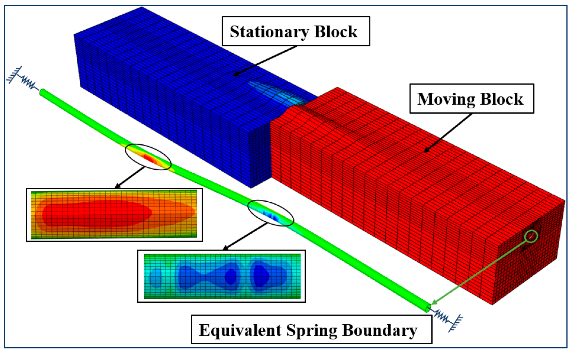
2. Equivalent-Spring Boundary-Based Finite Element Model of the Fault Crossing

2.1. Key Assumptions in the Finite Element Modeling

The mechanical response analysis of buried pipelines crossing active faults represents a highly nonlinear problem with numerous factors affecting the accuracy of simulation results. To enhance the reliability of the simulation model, appropriate simplifications were made in the finite element model through the following assumptions:
(1)
Fault movement is modeled as the relative displacement between the hanging wall and footwall along the fault plane, neglecting the influence of the fault fracture zone.
(2)
In the pipeline’s small deformation zones, it is assumed that no lateral displacement occurs between the pipeline and surrounding soil, with only minor axial strains present.
(3)
This study focuses specifically on the strain response of fault-crossing pipelines, excluding other factors such as seismic wave propagation and soil liquefaction.
(4)
The analyzed pipeline is assumed to be in optimal condition without initial defects, operating normally within its design lifespan.

2.2. Establishment of the Finite Element Model

2.2.1. Equivalent-Spring Boundary Theory

Large-displacement fault effects on pipelines can propagate hundreds of meters along the pipeline route. Theoretically, free boundary conditions can accurately replicate field conditions provided the numerical model achieves a sufficient spatial extent. However, this approach incurs prohibitive computational costs, with model length extension leading to exponential growth in solution time. Appropriate computational domain selection and the establishment of equivalent-spring boundaries were combined to build a model to achieve axial compensation for pipe ends. Based on current norms [41], from Equation (1) through to Equation (3), the empirical formula was employed to work out the soil’s axial friction force per unit length on the pipe’s outer surface:
f s = μ 2 W + W P
W = ρ s D H g
W p = π D t t ρ m + π 4 D 2 t 2 ρ g
where fs stands for the soil’s axial friction force per unit length, N/m; μ stands for the friction coefficient between the soil and the outer surface; W stands for soil gravity per unit length between the pipe top and the trench’s upper surface, N/m; Wp stands for the dead load of the pipe and internal medium combined, N/m; ρs stands for soil density, kg/m3; H stands for burial depth, m; g stands for gravitational acceleration, 9.8 m/s2; ρm stands for pipe material density, kg/m3; ρ stands for medium density, kg/m3; D stands for the outer diameter of the pipe, m; and t stands for the wall thickness of the pipe, m.
The relationship between external force and spring elongation was worked out and is shown in Equation (4) [42]:
F = 2 f s A E Δ L
where F stands for the external force on the nonlinear spring, N; A stands for pipe sectional area, m2; and ΔL stands for spring extension under external force, m.

2.2.2. Geometric Modeling and Meshing

The mechanical response of buried pipelines to fault displacement exhibits intrinsic nonlinearity due to multi-physics coupling effects, necessitating strategic model simplification. First, the effect of the fault zone’s width was omitted. Second, it was assumed that the axial strain occurred in the pipe’s minor deformed segments. Third, the impact of seismic waves, etc., was omitted.
To establish a computationally efficient yet accurate geometric model, it is necessary to select from the semi-infinite soil domain a specific computational domain for pipeline–soil interaction. In this study, the length and width of the computational domain for the chosen soil mass were about 60 and about 11 times the pipe diameter, respectively [19]. As for meshing, a total of 18160 S4R shell elements in Abaqus were designated for the pipe, a total of 32800 C3D8R solid elements were designated for the soil mass model, and structured meshing was used for the soil mass end faces. The model has a total of 55,412 nodes. Using the Abaqus mesh quality diagnostics, the meshes were checked, and the results showed that the meshes were of good quality. In this study, the explicit dynamics solver was used to solve the finite element model.

2.2.3. Nonlinear Contact and Boundary Conditions

Given material nonlinearity and complex contact interactions in the pipeline–soil system, this study selected general contact formulation with penalty friction (0.3) for tangential behavior and hard contact, allowing separation for normal behavior.
For boundary conditions, the top surface remains unconstrained to represent the free ground surface, while the bottom surfaces were fully fixed during the application of the gravity load. Normal displacement constraints were applied to the side surfaces, and the endpoints of equivalent spring boundaries were fully fixed. During the application of fault displacement to the moving block, the pipe spring remained stationary on the outer side, and the inner side was released. Meanwhile, the moving block allowed the spring’s inner side to be relieved of constraints, and the outer side of the moving block underwent displacement coupled with soil movement. When applying displacement to the moving block, the outer side of the spring on the stationary block’s pipe remained fixed, while the inner side was released from constraints. For the moving block’s pipeline, the inner side of the spring was released from constraints, and the outer side underwent synchronized displacement with the soil block. The finite element model is shown in Figure 1:

3. Model Experiment Design for Fault Crossings

3.1. Model Experiment Design Theory

Scaled physical modeling, as a similarity theory-driven experimental methodology, employs dimensionally reduced prototypes to replicate full-scale pipeline behavior under governing similitude laws. It can simulate and predict prototype-scale conditions in the scenario of a similar system of forces and check theoretical and simulation computations. The geometric similarity ratio, mechanical similitude indices, and data acquisition reliability of the model experiment are directly correlated to experiment accuracy [43].
If a model experiment involves a physical quantities and b fundamental dimensions, the system can be characterized by (ab) independent dimensionless π-terms through Buckingham’s π-theorem, and the combination of these dimensionless unknown parameters can be designated as π. It was assumed that the model experiment involves physical parameters (X1, X2Xa) and b fundamental dimensions, as shown in Equation (5):
f ( X 1 , X 2 , , X a ) = 0  
Equation (5) can be expressed in terms of a-b independent equations containing π, as shown in Equation (6):
φ ( π 1 , π 2 , , π a b ) = 0
Two similar physical processes must be equal in terms of the value of π. Then, the condition of similarity was determined based on the principle [44].
The study designed an experiment based on the object’s stress state, displacement field, and material property conditions. The equilibrium principle, geometric relationship, and linear elasticity equations were used to derive conditions similar to those shown in Equations (7) and (8) [45].
C γ C l = C σ ;   C ε C l = C δ ;   C σ = C ε C E
σ = γ H ,   γ = ρ g
where Cγ stands for the soil mass’ unit weight similarity ratio; Cl stands for the geometric similarity ratio; Cσ stands for the stress similarity ratio; Cε stands for the strain similarity ratio; Cδ stands for the displacement similarity ratio; CE stands for the elastic modulus similarity ratio; σ stands for stress, Pa; γ stands for the soil mass’ specific weight, N/m3; ρ stands for density, kg/m3; and g stands for gravitational acceleration, m/s2.
Geometric similarity is most crucial to the model experiment design, so Cl was determined as n. Based on Cl, Cσ of the pipe-surrounding soil mass was configured as 1, and Cσ was 1. Because Cl = n, the burial depth (H) for the model test was configured to be 1/n times that of the prototype-scale conditions. Because σ = γH, σ was 1/n times the original value. Consequently, to ensure Cσ = 1, Cγ should be 1/n, but soil material of such a weight was hard to obtain. Therefore, this study applied equivalent pressure application to the soil mass to ensure Cσ = 1. The effect was equivalent to an n-fold weight increase for the soil mass.
The equivalent pressure application on the soil mass was calculated using Equation (9):
p = γ ( H p H m )
where Hp stands for the prototype-scale burial depth, m, and Hm stands for the model pipe’s burial depth, m.
After the equivalent pressure was applied and the soil mass’ stress similarity ratio (Cσ) became 1, the elastic modulus similarity ratio and strain similarity ratio (CECε) became 1, as indicated in Equation (7). In this study, the materials working under prototype-scale conditions were selected for the model experiment to ensure the physical quantities had similarity ratios as shown in Table 1.

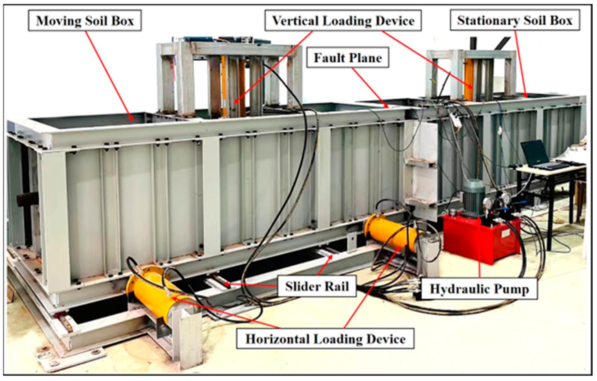
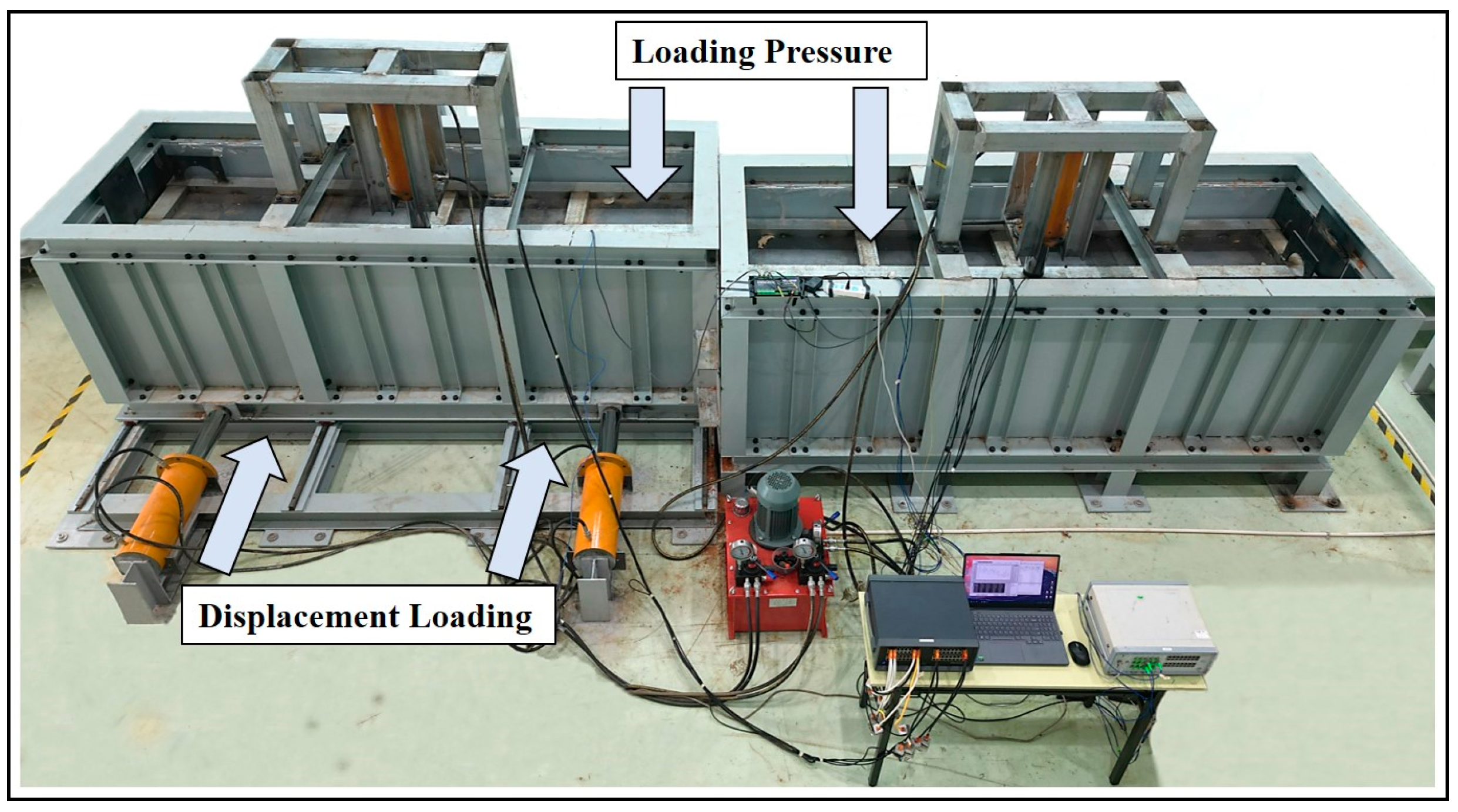
3.2. Experimental Platform Design

Based on the similarity ratios, the basic length, width, and height of the experimental platform were configured as 6.3 m, 1.2 m, and 1.1 m, respectively. To eliminate the boundary effects on the structure, the boxes must be more than 60D long and more than 11D wide; therefore, the platform can conduct experiments on pipes with a diameter of 100 mm or less.
The platform was designed for strike-slip fault crossings based on the relevant basic dimensions, stability, and interchangeability. The platform comprised primarily the stationary soil box, moving soil box, slider rails, vertical loading devices, and horizontal loading devices. The fault angle was 90°. The horizontal loading devices enabled the moving soil box to slide along the slider rails to simulate displacement at the strike-slip fault crossing. The vertical loading devices were composed of jacks and compression plates. The compression plates resting on the pipeline–soil system applied pressure to the soil mass with the aid of the jacks to achieve the required stress similarity ratio. The entire platform is shown in Figure 2.

3.3. Design of Model Experiment Conditions

The research was conducted under prototype-scale conditions with soil extracted from the site and a pipe with a 1219 mm diameter. The design’s geometric similarity ratio (n) was 13.7. The pipe measured 89 mm in diameter and 4 mm in thickness. The pipe and the soil mass worked under prototype-scale conditions. Based on the similarity ratios proposed in this study, the relationship between the prototype-scale and experimental conditions is shown in Table 2.
The prototype-scale burial depth (Hp) was 2 m. Based on the geometric similarity ratio, the model burial depth (Hm) was determined to be 0.15 m. To achieve a stress similarity ratio (Cσ) of 1, there must be an additional 0.04 MPa pressure on the soil mass, as shown in Equation (8).

4. Model Experimental System Installation

4.1. FEA of the Experimental Conditions

The initial phase to achieve the proper installation of strain sensors is to simulate and analyze the experimental conditions to evaluate the pipe’s global strain distribution. A test of the experimental material must be performed to enhance the reliability and accuracy of the finite element model and the constitutive model. The basic parameters of the X42 pipe are shown in Table 3.
The mechanical performance testing was conducted using a universal testing machine (UTM). Uniaxial tensile tests were conducted to determine the true stress–strain relationship with mathematical definitions, as shown in Figure 3.
An SLB-1 stress and strain-controlled triaxial shear tester was used in combination with a high-pressure oedometer to test the soil mass. The soil parameter tests are shown in Figure 4.
The Mohr–Coulomb model parameters of the soil obtained from the experiment are shown in Table 4.
Following the determination of the material’s constitutive parameters, a model was built to simulate the experimental conditions using the FEA described in this study. The boundary conditions of the finite element model were consistent with the experimental conditions. The axial strain distribution curve along the pipeline was derived by simulation under the experimental conditions, as shown in Figure 5.

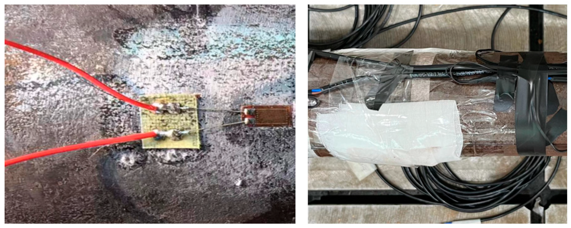
4.2. Sensor Selection and Deployment

Because the pipe’s axial strain was primarily distributed within 0.5–1 m from the fault plane, as shown by the simulation results under the experimental conditions, sensors were more closely deployed within the range, and only a few sensors were deployed within the remaining part within a 2 m distance from the fault plane. Based on FEA results under experimental conditions, the maximum axial strain in the pipe is predominantly distributed within 0.5-1 m from the fault plane. Accordingly, a higher density of sensors was deployed in this critical zone, while only a limited number of sensors were placed in the remaining section (2 m from the fault plane). The strain test involved a 120-10AA foil strain gauge with a resistance of 120 ± 1 Ω, a sensitivity of 2.0 ± 1%, and a range of 20,000 με. The sensors were deployed as shown in Figure 6, and the sensor installation strategy and protection scheme are shown in Figure 7.

4.3. Experiment System Installation

The experiment system was installed after the determination of the test materials, sensor configurations, and deployment locations. First, the sensors were installed at the corresponding locations according to the deployment scheme. Second, soil was transferred into the boxes in steps in the form of a 100 mm thick layer at a time until reaching the burial depth. Following pipe laying, more soil was transferred into the boxes to a predetermined height before further compaction, intending to achieve the prescribed density. Finally, the vertical loading devices were installed, and the sensors were connected to the data acquisition system, computer, etc., to complete the installation of the entire experiment system.

4.4. Soil Loading

Following the initialization of the model experiment, the complete experimental system was installed and made operational. First, soil loading was commenced using vertical loading devices until soil stress reached the prescribed stress similarity ratio (0.04 MPa). Subsequently, the hydraulic system was switched to the pressure maintenance mode. Second, the moving soil box was loaded using the horizontal loading devices in a way that dislocated the moving soil box from the stationary soil box. The boxes were loaded until 0.4 m, with 0.1 m at a time. The loading operation for the experiment system is shown in Figure 8.

5. Fault-Crossing Experiment Evaluation

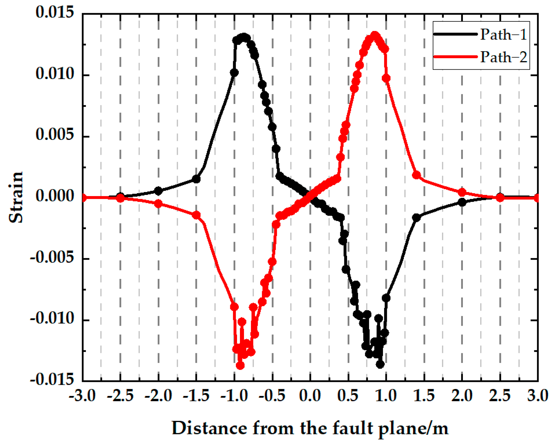
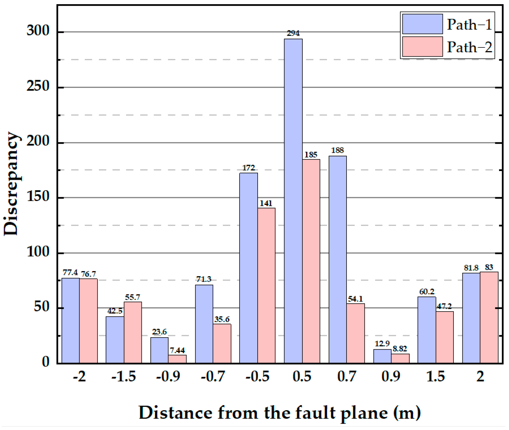
5.1. Analysis of Model Experimental Results

The pipe was lifted out of the soil after the loading experiment and strain data collection. The data were compared with the FEA results under the experimental conditions to obtain the details of pipe deformation under fault displacement, as shown in Figure 9. It was observed that due to fault displacement, the model pipe underwent evident deformation at locations largely distributed antisymmetrically, with the greatest strain occurring at a certain distance from the fault plane. Plus, in terms of deformation, the model pipe exhibited the same phenomena as in the FEA, indicating that the FEA can reflect pipe deformation under fault displacement satisfactorily.
The model experiment data were extracted as a basis for drawing strain distribution curves corresponding to the two paths in the pipe’s axial direction in different scenarios of fault displacement. To mitigate the influence of uncertainty factors, we conducted four identical experimental trials and calculated the average of the corresponding results. The curves were compared with the FEA results under model working conditions.
As shown in Figure 10, the maximum values of tensile strain and compressive strain were not symmetrical relative to the fault plane. Under minor fault displacements, the pipeline experienced lower overall strain levels without significant strain concentration. However, as fault displacement increased, specific pipeline segments exhibited enhanced strain concentration and more intense strain responses. Notably, the strain distribution along the tensile stress region of the pipeline remained relatively uniform.
The discrepancies between the simulation and experimental results for 0.4m displacement loading are demonstrated in Figure 11. The discrepancy value at 0.9m from the fault plane is smaller, while the discrepancies are larger closer to the fault surface. Combined with Figure 10’s analysis, the deformation of the pipe in the FEA is a gradual process, so the curve is smoother, while the results obtained from the test show large deformations in the local areas of the pipe, and the deformation area is more concentrated, which leads to a larger discrepancy in other locations. However, the simulation and test results have the same trend, indicating that the FEA could reflect the maximum strain data in the model experiment and at corresponding locations.

5.2. Analysis of Results for Prototype-Scale Conditions Analysis and Comparison of Prototype-Scale FEA Results with Experimental Results

Similarity ratio inverse modeling and FEA were conducted for the prototype-scale conditions to check model experiment design schemes and the reliability of the FEA. The pipes and soil mass working under prototype-scale conditions were the same as those used in the model experiment.
First, the model experimental data underwent similarity ratio inverse modeling. The pipe’s maximum strain and the corresponding location under prototype-scale conditions were worked out based on a strain similarity ratio (Cε) of 1 and a geometric similarity ratio (Cl) of 13.7. Subsequently, the FEA proposed in this study was employed to build the finite element model based on the equivalent-spring boundaries of the fault crossing. The pipeline–soil calculation domain was configured as 80 m × 15 m × 10 m. As shown in Figure 12, the FEA results based on the prototype-scale conditions were worked out, and the maximum axial tensile and compressive axial strains and the locations were derived.
Next, the similarity ratio inverse modeling results were compared with the FEA results to produce the findings shown in Table 5.
As can be seen from Table 5, under prototype-scale conditions, the maximum tensile strain derived based on similarity ratio inverse modeling deviated by 17.73% from that derived from FEA, and the maximum compressive strain derived based on similarity ratio inverse modeling deviated by 15.04% from that derived from FEA. Meanwhile, under prototype-scale conditions, the location of the maximum tensile strain derived based on similarity ratio inverse modeling deviated by approximately 8.11% from that derived based on FEA, and the location of the maximum compressive strain derived based on similarity ratio inverse modeling deviated by 5.35% from that derived based on FEA. Consequently, the model experimental inversion findings based on the similarity ratio proved to be largely in agreement with the findings of the FEA of the prototype-scale conditions. The findings substantiated the reliability of the model’s experiment design. In addition, it signified that the equivalent-spring boundaries based on FEA were accurate enough to predict the strain response well.

6. Conclusions

This study proposed a set of simulation and experiment methods designed to analyze the strain response of cross-fault buried pipelines accurately. First, a method was presented to build a finite element model of the fault crossing based on the equivalent spring boundary. Secondly, an experimental platform was erected to obtain model experimental data. Lastly, the prototype-scale conditions were analyzed based on the similarity ratio inverse modeling of the model experimental results and FEA to finish evaluating the set of strain response analyses. The major conclusions are presented as follows:
First, as indicated by the model experiment, the movement of the strike-slip fault caused the pipe to undergo “S”-like antisymmetric deformation, with the maximum strain observed near the fault plane. The model test results consisted highly of the pipe’s axial strain distribution curves derived from the FEA and substantiated the finite element method’s accuracy concerning the representation of the maximum strain values and locations under the experimental conditions.
Second, as shown in the analysis with prototype-scale conditions, under prototype-scale conditions, the maximum tensile strain derived based on similarity ratio inverse modeling deviated by 17.73% from that derived from FEA, and the maximum compressive strain derived based on similarity ratio inverse modeling deviated by 15.04% from that derived from FEA. Meanwhile, under prototype-scale conditions, the location of the maximum tensile strain derived based on similarity ratio inverse modeling deviated by approximately 8.11% from that derived based on FEA, and the location of the maximum compressive strain derived based on similarity ratio inverse modeling deviated by 5.35% from that derived based on FEA. These findings substantiated the reliability of the model experiment as well as the accuracy of the finite element model this study built for cross-fault buried pipelines.
For large-diameter, full-scale pipelines, the experimental investigation of strain response presents significant challenges. FEA provides an effective alternative for predicting strain behavior in fracture zones. The current research methodology involves three mutually validating components: (1) establishing a 1:1 finite element model based on the experimental setup, (2) verifying the finite element model’s accuracy through experimental results, and (3) developing a prototype-scale finite element model using similarity theory. This validated finite element model can be extended to predict the behavior of full-scale pipelines under actual working conditions and further serve as a foundation for simulating more complex scenarios. However, compared with the test conditions in this study, the situation in practice is more complex, and there are many factors to consider, so there are still many aspects of this study that could be explored further. However, compared to the model test conditions, the actual operating conditions are more severe, and thus this study has certain limitations. For example, The model test of this study is large and only considers the case of 90° strike-slip faults, and different forms of displacement such as oblique faults can be considered in the follow-up; the model test did not consider the influence of internal pressure in practical applications, so the follow-up work could investigate this in more detail.

Author Contributions

Conceptualization, Y.L. (Yuan Li); Methodology, S.C. and Z.C.; Software, S.C.; Validation, L.F. and J.W.; Formal Analysis, Y.H.; Investigation, W.X.; Resources, W.X.; Data Curation, Y.H. and Y.L. (Yanbin Li); Writing—Original Draft Preparation, S.C.; Writing—Review & Editing, Z.C.; Visualization, L.F.; Supervision, J.W.; Project Administration, Y.L. (Yanbin Li); Funding Acquisition, Y.L. (Yuan Li). All authors have read and agreed to the published version of the manuscript.

Funding

This research was funded by [Large Strain-based Oil and Gas Pipe Safety Early Warning Technology] grant number [No: GWHT20230013782] And The APC was funded by [No: GWHT20230013782].

Data Availability Statement

The original contributions presented in this study are included in the article. Further inquiries can be directed to the corresponding author(s).

Conflicts of Interest

Author Yanbin Li was employed by the company Construction Project Management Branch of National Petroleum and Natural Gas Pipeline Network Group Corporation. The remaining authors declare that the research was conducted in the absence of any commercial or financial relationships that could be construed as a potential conflict of interest.

References

  1. O’Rourke, T.D.; Mccaffrey, M.A. Buried pipeline response to permanent earthquake ground movements. In Proceedings of the Eighth World Conference on Earthquake Engineering, San Francisco, CA, USA, 21–28 July 1984; Prentice-Hall, Inc.: Upper Saddle River, NJ, USA, 1984; Volume 7. [Google Scholar]
  2. Chen, W.W.; Shih, B.J.; Chen, Y.C.; Hung, J.H.; Hwang, H.H. Seismic response of natural gas and water pipelines in the ji-ji earthquake. Soil Dyn. Earthq. Eng. 2002, 22, 1209–1214. [Google Scholar] [CrossRef]
  3. Wang, X.; Guo, E.; Zhang, M. Analysis of and solutions to seismic damages of gas pipeline networks in the Wenchuan earthquake. World Earthq. Eng. 2012, 28, 44–50. [Google Scholar]
  4. Vigny, C.; Socquet, A. The 2010 Mw 8.8 Maule megathrust earthquake of central Chile, monitored by GPS. Science 2011, 332, 1417–1421. [Google Scholar] [CrossRef]
  5. Chiou, Y.J.; Chi, S.Y.; Chang, H.Y. A study on buried pipeline response to fault movement. J. Press. Vessel. Technol.-Trans. Asme 1994, 116, 36–41. [Google Scholar] [CrossRef]
  6. Newmark, N.M.; Hall, W.J. Pipeline design to resist large fault displacement. In Proceedings of the US National Conference on Earthquake Engineering, Ann Arbor, MI, USA, 18–20 June 1975; pp. 416–425. [Google Scholar]
  7. Kennedy, R.P.; Williamson, R.A.; Chow, A.M. Fault movement effects on buried oil pipeline. J. Transp. Eng. 1977, 103, 617–633. [Google Scholar]
  8. Wang, L.R.L.; Yeh, Y.H. A refined seismic analysis and design of buried pipeline for fault movement. Earthq. Eng. Struct. Dyn. 1985, 13, 75–96. [Google Scholar] [CrossRef]
  9. Wang, L.R.L.; Wang, L.J. Parametric study of buried pipelines due to large fault movements. In Proceedings of Third China-Japan-US Trilateral Symposium on Lifeline Earthquake Engineering; Kobe Univ. of Japan: Kobe, Japan, 1995; pp. 165–172. [Google Scholar]
  10. Karamitros, D.K.; Bouckovalas, G.D.; Kouretzis, G.P. Stress analysis of buried steel pipelines at strike-slip fault crossings. Soil Dyn. Earthq. Eng. 2007, 27, 200–211. [Google Scholar] [CrossRef]
  11. Trifonov, O.V.; Cherniy, V.P. A semi-analytical approach to a nonlinear stress strain analysis of buried steel pipelines crossing active faults. Soil Dyn. Earthq. Eng. 2010, 30, 1298–1308. [Google Scholar] [CrossRef]
  12. Trifonov, O.V.; Cherniy, V.P. Elastoplastic stress-strain analysis of buried steel pipelines subjected to fault displacements with account for service loads. Soil Dyn. Earthq. Eng. 2012, 33, 54–62. [Google Scholar] [CrossRef]
  13. Guo, E.; Feng, Q. A seismic analysis method for buried steel pipes crossing faults. Earthq. Eng. Eng. Vib. 1999, 19, 43–47. [Google Scholar]
  14. Takada, S.; Hassani, N.; Fukuda, K. A new proposal for simplified design of buried steel pipes crossing active faults. Earthq. Eng. Struct. Dyn. 2001, 30, 1243–1257. [Google Scholar] [CrossRef]
  15. Liu, A.W.; Hu, Y.X.; Zhao, F.X.; Li, X.J.; Takada, S.; Zhao, L. An equivalent-boundary method for the shell analysis of buried pipelines under fault movement. Acta Seismol. Sin. 2004, 26 (Suppl. S1), 141–147. [Google Scholar] [CrossRef]
  16. Yan, X.; Zhang, L.; Yang, X. Strain response study of oil-gas pipelines crossing earthquake faults based on the pipe-soil coupling and the large deformation shell model. China Civ. Eng. J. 2010, 43, 132–139. [Google Scholar]
  17. Joshi, S.; Prashant, A.; Deb, A.; Jain, S.K. Analysis of buried pipelines subjected to reverse fault motion. Soil Dyn. Earthq. Eng. 2011, 31, 930–940. [Google Scholar] [CrossRef]
  18. Fadaee, M.; Farzaneganpour, F.; Anastasopoulos, I. Response of buried pipeline subjected to reverse faulting. Soil Dyn. Earthq. Eng. 2020, 132, 1–9. [Google Scholar] [CrossRef]
  19. Vazouras, P.; Karamanos, S.A.; Dakoulas, P. Mechanical behavior of buried steel pipes crossing active strike-slip faults. Soil Dyn. Earthq. Eng. 2012, 41, 164–180. [Google Scholar] [CrossRef]
  20. Li, L.; Qiao, L.; Fan, J.; Zhang, Y. Mechanical behavior of polyethylene pipes under strike-slip fault movements. Polymers 2022, 14, 987. [Google Scholar] [CrossRef]
  21. Zhang, R.; Wang, C.; Li, S.; Zhang, J.; Liu, W. Numerical simulation study on the performance of buried pipelines under the action of faults. Appl. Sci. 2023, 13, 11266. [Google Scholar] [CrossRef]
  22. Huang, D.-L.; Cen, H.; Wang, H.-Y.; Liu, Q.; Zong, Z.-L.; Tang, A.-P. Tang. Study on response patterns and influencing factors of buried pipelines with corrosion defects under fault action. Appl. Eng. Sci. 2024, 18, 100176. [Google Scholar] [CrossRef]
  23. Makrakis, N.; Psarropoulos, P.N.; Sextos, A.; Tsompanakis, Y. Do Soft Soil Layers Reduce the Seismic Kinematic Distress of Onshore High-Pressure Gas Pipelines? Bull. Earthq. Eng. 2024, 22, 159–189. [Google Scholar] [CrossRef]
  24. Zhang, W.; Ayello, F.; Honegger, D.; Taciroglu, E.; Bozorgnia, Y. Comprehensive numerical analyses of the seismic performance of natural gas pipelines crossing earthquake faults. Earthq. Spectra 2022, 38, 1661–1682. [Google Scholar] [CrossRef]
  25. Gu, X.-T.; Zang, X.-R.; Zhang, Z.-Y.; Yang, P.; Miao, W.-Z.; Cao, P.; Zhao, B. Reliability analysis of large-diameter high-grade-steel natural gas pipelines under fault action. Pet. Sci. 2022, 19, 2387–2398. [Google Scholar] [CrossRef]
  26. Tan, N.; Zhou, L.; Zheng, W.; Song, H.; Sun, Z.; Wang, Z.; Wang, G.; Wang, G.; Zhang, L.; Zhou, X. Using finite element method for stress-strain evaluation of commonly used buried pipelines in fault. Energies 2022, 15, 1655. [Google Scholar] [CrossRef]
  27. Takada, S. Experimental study on the mechanical properties of PVC pipes during soil subsidence. In Earthquake Resistance of Underground Pipelines; Hong, Z.L., Ed.; Academic Book Press: Beijing, China, 1987; pp. 204–214. [Google Scholar]
  28. Sim, W.W.; Towhata, I.; Yamada, S.; Moinet, G.J.M. Shaking table tests modelling small diameter pipes crossing a vertical fault. Soil Dyn. Earthq. Eng. 2012, 35, 59–71. [Google Scholar] [CrossRef]
  29. Zhang, Z.; Wang, J.; Xu, Y. Shaking table test for cross-fault buried pipelines (I)—Model design. China Civ. Eng. J. 2011, 44, 93–98. [Google Scholar]
  30. Deng, L.S.; Zhang, W.Z.; Dai, Y.; Fan, W.; Li, Y.B.; Ren, S.; Li, P. Seismic response of a water transmission pipeline across a fault zone adopting a large-scale vibration table test. Front. Earth Sci. 2021, 9, 777551. [Google Scholar] [CrossRef]
  31. Liu, W.; Huang, C.J.; Zhang, S.F.; Song, Z.Y. Centrifuge tests of large-diameter steel pipes crossing strike-slip faults. Eng. Struct. 2023, 279, 115124. [Google Scholar] [CrossRef]
  32. Liu, W.; Huang, C.J.; Zhang, S.F.; Miao, H.Q. Centrifuge test of large-diameter segmented ductile iron pipes crossing strike-slip faults. Structures 2023, 57, 105218. [Google Scholar] [CrossRef]
  33. Rojhani, M.; Moradi, M.; Galandarzadeh, A.; Takada, S. Centrifuge modeling of buried continuous pipelines subjected to reverse faulting. Can. Geotech. J. 2012, 49, 659–670. [Google Scholar] [CrossRef]
  34. Choo, Y.W.; Abdoun, T.H.; O’Rourke, M.J.; Ha, D. Remediation for buried pipeline systems under permanent ground deformation. Soil Dyn. Earthq. Eng. 2007, 27, 1043–1055. [Google Scholar] [CrossRef]
  35. Ha, D.; Abdoun, T.H.; O’Rourke, M.J.; Symans, M.D.; O’Rourke, T.D.; Palmer, M.C.; Stewart, H.E. Centrifuge modeling of earthquake effects on buried high-density polyethylene (hdpe) pipelines crossing fault zones. J. Geotech. Geoenviron. Eng. 2008, 134, 1501–1515. [Google Scholar] [CrossRef]
  36. Rofooei, F.R.; Jalali, H.H.; Attari, N.K.A.; Alavi, M. Full-scale laboratory testing of buried pipelines subjected to permanent ground displacement caused by reverse faulting. In Proceedings of the 15th World Conference on Earthquake Engineering, Lisbon, Portugal, 24–28 September 2012. [Google Scholar]
  37. Kim, J.; Nadukuru, S.S.; Pour-Ghaz, M.; Lynch, J.P.; Michalowski, R.L.; Bradshaw, A.S.; Green, R.A.; Weiss, W.J. Assessment of the behavior of buried concrete pipelines subjected to ground rupture: Experimental study. J. Pipeline Syst. Eng. Pract. 2012, 3, 8–16. [Google Scholar] [CrossRef]
  38. Rofooei, F.R.; Jalali, H.H.; Attari, N.K.A.; Kenarangi, H.; Samadian, M. Parametric study of buried steel and high density polyethylene gas pipelines due to oblique-reverse faulting. Can. J. Civ. Eng. 2015, 42, 178–189. [Google Scholar] [CrossRef]
  39. Zhang, L. Numerical Simulations of Full Scale Tests Investigating Effect of Fault Movement on Buried Pipeline. Ph.D. Thesis, Delft University of Technology, Delft, The Netherlands, 2015. [Google Scholar]
  40. Demofonti, G.; Ferino, J.; Karamanos, S.; Vazouras, P.; Dakoulas, P. An integrated experimental—Numerical approach to predict strain demand for buried steel pipelines in geo-hazardous areas. In Proceedings of the Rio Pipeline Conference and Exposition, Rio de Janeiro, Brazil, 24–26 September 2013. [Google Scholar]
  41. Ministry of Housing and Urban-Rural Development of the People’s Republic of China. Seismic Technical Code for Oil and Gas Transmission Pipeline Engineering; Beijing China Planning Publishing House: Beijing China, 2017; pp. 22–23. [Google Scholar]
  42. Li, Y.; Yu, J.X.; Yu, Y. Research on local buckling and strain response prediction of submarine pipelines across strike—slip faults. World Earthq. Eng. 2019, 35, 105–131. [Google Scholar]
  43. Luo, X.; Cheng, S.; Zhang, Z.; Tang, K. Study of similarity theory of geomechanical model experiment in an electromagnetic field. Rock Soil Mech. 2011, 32, 1035–1039. [Google Scholar]
  44. Jiang, H.; Li, R.; Yan, R. Impact of geometric scale similarity levels on tunnel model experiment and its deductive computational difference. Rock Soil Mech. 2015, 36 (Suppl. S1), 270–276. [Google Scholar]
  45. Xiong, T.F.; Shao, S.; Wang, T.M.; Gao, Z.H. Research on physical model experiment of Xi’an metro tunnels orthogonally crossing ground fissures. Rock Soil Mech. 2010, 31, 179–186. [Google Scholar]
Figure 1. Finite element modeling of a fault crossing.
Symmetry 17 00501 g001
Figure 2. Experimental platform for the strike-slip fault crossing.
Symmetry 17 00501 g002
Figure 3. True stress–strain curve of the model pipe.
Symmetry 17 00501 g003
Figure 4. Soil parameter test.
Symmetry 17 00501 g004
Figure 5. Axial strain distribution.
Symmetry 17 00501 g005
Figure 6. Foil strain gauge deployment for the model pipe.
Symmetry 17 00501 g006
Figure 7. Sensor installation and protection.
Symmetry 17 00501 g007
Figure 8. Loading the experiment system.
Symmetry 17 00501 g008
Figure 9. Pipe deformation at a strike-slip fault crossing.
Symmetry 17 00501 g009
Figure 10. Model experiment and pipe strain distribution curves derived using the finite element.
Symmetry 17 00501 g010
Figure 11. Discrepancy analysis under 0.4 m displacement loading.
Symmetry 17 00501 g011
Figure 12. Simulated strain distribution curve under prototype-scale conditions.
Symmetry 17 00501 g012
Table 1. Similarity ratios for each physical quantity.
Physical QuantityRelationsSimilarity Constant
εCε1
lCln
ρCρ1
ECE1
μCμ1
γCγ = CρCg1/n
σCσ = CρCgCl1
δCδn
HCHn
Table 2. Prototype-scale conditions vs. experimental conditions.
Physical QuantityD/mmt/mmH/mδ/mσ/MPa
Prototype-scale conditions121954.825.480
Experimental conditions8940.150.40.04
Table 3. Material parameters of the test pipes.
D/mmt/mmE/MPavρ/kg × m³
894210,0000.37850
Table 4. Soil parameters.
E/MPavρ/kg × m³ϕc/kPa
6.00.422307.3654.42
Table 5. Similarity ratio inverse modeling results vs. FEA results.
Physical Quantityεtεclεt/mlεc/m
Model finite element0.01330.01370.840.92
Model experiment0.01410.01330.90.9
Inversion0.01410.013312.3312.33
Finite element analysis0.01160.011311.3311.67
D-value17.73%15.04%8.11%5.35%
Disclaimer/Publisher’s Note: The statements, opinions and data contained in all publications are solely those of the individual author(s) and contributor(s) and not of MDPI and/or the editor(s). MDPI and/or the editor(s) disclaim responsibility for any injury to people or property resulting from any ideas, methods, instructions or products referred to in the content.

