Article

High-Performance Sensorless Control of Induction Motors via ANFIS and NPC Inverter Topology

1
National School of Engineers of Gabes, Gabes University, Gabes 6029, Tunisia
2
National School of Engineers of Gafsa, Gafsa University, Gafsa 2112, Tunisia
*
Author to whom correspondence should be addressed.
Symmetry 2025, 17(11), 1996; https://doi.org/10.3390/sym17111996
Submission received: 1 September 2025 / Revised: 2 November 2025 / Accepted: 12 November 2025 / Published: 18 November 2025
(This article belongs to the Section Engineering and Materials)

Abstract

This paper presents a high-performance sensorless control strategy for induction motors using an Adaptive Neuro-Fuzzy Inference System (ANFIS) for rotor speed estimation, eliminating the need for mechanical sensors. The ANFIS approach leverages stator voltages and currents, reducing costs and complexity. The motor is controlled via Indirect Stator Field Orientation Control (ISFOC) with a three-level Neutral–Point–Clamped (NPC) inverter employing Space Vector Modulation (SVM). Symmetry in the motor’s magnetic structure and SVM’s switching patterns enhances control precision, stability, and efficiency while minimizing harmonic distortion. Simulation results validate the proposed ANFIS-based estimator’s superior performance compared to a MRAS-based Luenberger observer under various operating conditions, demonstrating accurate speed tracking and robustness against load disturbances.

1. Introduction

Induction motors are widely used in systems that control mechanical motion as well as in household appliances. Their simple and robust construction, low energy consumption, minimal maintenance requirements, and compatibility with AC drives make them a preferred choice in industries such as aviation, petrochemicals, and healthcare. However, their control remains challenging due to the nonlinear coupling between flux and torque, which makes performance regulation more complex than in DC motors. Despite this complexity, advancements in control devices and techniques have significantly expanded the use of induction motors in industrial applications.
One of the most prominent control strategies is flux vector control, introduced by Blaschke in 1972 [1,2,3]. This method enables precise torque and speed control by decoupling the flux and torque components, allowing induction motors to achieve performance comparable to that of DC motors in demanding applications. This strategy exploits the inherent symmetry of the motor’s magnetic and structural properties to ensure effective decoupled control. The balanced and symmetrical design of the stator and rotor windings promotes a uniform magnetic field distribution, directly supporting the principles of vector control and improving both precision and robustness.
The device that converts DC power into AC power is known as an inverter. The inverter’s DC input, typically obtained from a rectifier or a battery, is converted into an alternating output signal by periodically reversing the current flow. The frequency of the output voltage can be adjusted as needed. Inverters are widely used in various applications, including control systems, railway traction, electric vehicles [4,5], and marine propulsion systems.
Among inverter topologies, multilevel inverters—particularly the three-level Neutral–Point–Clamped (NPC) inverter—have gained significant attention due to their ability to produce high-quality output voltages with reduced harmonic distortion [6,7,8,9,10]. The diode-clamped configuration is the most common multilevel design, using diodes as clamping devices to stabilize the DC bus voltage and generate stepped output levels. Nabae, Takahashi, and Akagi first proposed this configuration in 1981 [11], introducing a three-level diode-clamped inverter. The shared DC bus among phases exploits electrical symmetry, reducing the number of capacitors required and maintaining uniform voltage levels across all phases. This topological symmetry enhances efficiency, minimizes electromagnetic interference, and improves thermal balance, making it ideal for high-performance applications such as adjustable-speed drives and high-voltage interconnections [12,13,14,15,16].
In motor drive systems, inverters generate variable voltage outputs for the motor, and the inverter’s performance depends largely on its control strategy. The literature offers various inverter control techniques, including Space Vector Modulation (SVM) [17,18] and conventional Pulse Width Modulation (PWM). Recently, the SVM approach has attracted considerable interest [7]. Multilevel inverters often employ SVM, an advanced PWM technique, to reduce harmonic distortion and enhance voltage utilization. SVM synthesizes the desired output voltage by representing the inverter’s switching states as vectors in the complex plane. The geometric symmetry inherent in this space vector representation minimizes switching losses while maintaining voltage balance—crucial for the precise and efficient operation of induction motor drives [12,14,16,19,20,21].
In induction motor drive systems, sensors such as tachometers, resolvers, or digital encoders are typically used to measure rotor speed and provide feedback signals. However, these sensors increase system cost, occupy additional space, and can compromise reliability due to wiring complexity and potential failure points. Eliminating such sensors can simplify the system and enhance its reliability. Consequently, several sensorless speed estimation methods have been proposed, including the Model Reference Adaptive System (MRAS) [22,23,24,25,26,27], Extended Kalman Filter (EKF) [28,29], Sliding Mode Observer (SMO) [30,31,32,33], simplified nonlinear observers, MRAS-based Kalman filters [34], and MRAS-based Luenberger observers [34]. Model-based methods, however, rely heavily on precise mathematical models, making them sensitive to parameter variations and modeling inaccuracies. Moreover, these algorithms often involve complex computations and can struggle to achieve accurate speed estimation under varying operating conditions [19,35,36,37].
In contrast, soft computing techniques such as the Fuzzy Inference System (FIS), Artificial Neural Networks (ANN), and Adaptive Neuro-Fuzzy Inference System (ANFIS) do not require explicit mathematical models, making them particularly effective for power electronics and observer-based control of induction machines [22,38,39,40,41,42]. Their main advantage lies in the reduced mathematical complexity and adaptability to nonlinearities and uncertainties. However, conventional fuzzy-logic controllers (FLCs) typically operate over limited speed ranges and require extensive manual tuning. Likewise, developing comprehensive training datasets for ANNs that accurately represent all operating modes remains challenging [36,43,44,45].
To address these limitations, ANFIS combines the interpretability of fuzzy logic with the learning capability of neural networks. This hybrid structure offers rapid convergence through hybrid learning and allows flexible design of membership functions. ANFIS exhibits superior tracking accuracy and adaptability compared to conventional observers [35]. Interestingly, symmetry also plays an important role in ANFIS design: a symmetric structure in training data and membership function distribution enhances generalization, improves convergence behavior, and reduces overfitting, resulting in smoother estimator performance.
To exploit the combined benefits of ANFIS, the three-level NPC inverter, and the SVM control strategy, this study investigates a sensorless Indirect Stator Flux Orientation Control (ISFOC) scheme for three-phase induction motors. An efficient rotor speed estimator based on ANFIS is developed to overcome the limitations of traditional sensors. The motor is powered through a three-level NPC inverter controlled via SVM. To validate the effectiveness of the proposed estimator, a comparative analysis with a MRAS-based Luenberger observer is performed under various operating conditions, including variable speeds, field-weakening regions, and load disturbances. The proposed ANFIS-based ISFOC scheme achieves accurate speed tracking, smooth operation, and reduced sensitivity to system disturbances.
The remainder of this paper is organized as follows. Section 2 presents the mathematical model of the induction motor. Section 3 describes the ISFOC method. Section 4 details the design of the ANFIS speed estimator. Section 5 discusses the configuration of the three-level NPC inverter. Section 6 provides simulation results, followed by the conclusions and directions for future work.

2. Induction Motor

To advance toward the simulation and implementation stages, it is first necessary to perform the fundamental step of modeling. In this stage, selecting an appropriate model is essential to accurately capture and understand the underlying phenomena. The system designer’s objective is to ensure that the model highlights the key behaviors of the system and allows reliable prediction of its performance under both dynamic and steady-state conditions. Table 1 presents different motor parameters that are used thereafter in equation system.
The dynamic representation of the three-phase induction motor is outlined through Equations (1)–(7).
V d s = r s i d s + d ϕ d s d t
V q s = r s i q s + ω s ϕ d s
V d r = 0 = r r i d r + d ϕ d r d t ( ω s ω ) ϕ q r
V q r = 0 = r r i q r + d ϕ q r d t + ( ω s ω ) ϕ d r
where
ω r = ω s ω
The electromagnetic structures of the three-phase induction motor in the (d,q) reference model are expressed by the fluxes of the stator and rotor (6).
ϕ d s = L s i d s + M i d r ϕ q s = L s i q s + M i q r ϕ d r = L r i d r + M i d s ϕ q r = L r i q r + M i q s
The electromagnetic torque of a three-phase induction motor, as a function of the rotor flux and the stator currents, can be represented by the subsequent Equation (7).
C e = p ( ϕ d s i q s ϕ q s i d s )
The corresponding variables in the (d,q) reference frame are derived from the (a, b, c) variables through a mathematical transformation using the matrix conversion indicated by Equation (8), commonly referred to as the Park transformation.
P β = 2 3 cos ( β ) cos ( β 2 π 3 ) cos ( β + 2 π 3 ) sin ( β ) sin ( β 2 π 3 ) sin ( β + 2 π 3 ) 1 2 1 2 1 2

3. ISFOC Vector Control by Stator Flux Orientation

To manage the vector flux of an asynchronous machine through stator flux orientation, it is necessary to align the reference frame (d, q) with the stator flux, which involves orienting along the d axis by nullifying the q axis stator flux component (9), as it mentioned in Figure 1. Given the ease of observing stator currents, the torque equations associated with them are utilized to regulate the induction machine’s torque and speed. Critical reference parameters include the slip speed and the direct stator flux [46].
ϕ d s : ϕ s = ϕ d s
i d s = 1 + τ r s ϕ d s + L s τ r σ i q s ω r L s τ r σ s + 1
i q s = τ r 1 σ ϕ d s L s ( 1 + τ r σ s ) 2 + ( τ r σ ω r ) 2 ω r
V d s = r s i d s + s ϕ d s
V q s = r s i q s + ω s ϕ d s
C e = p ϕ d s 2 τ r 1 σ L s ( 1 + τ r σ s ) 2 + ( τ r σ ω r ) 2 ω r
C e = p ϕ d s 2 τ r 1 σ L s ( 1 + τ r σ s ) 2 ω r

4. Speed Estimation

4.1. ANFIS Algorithm

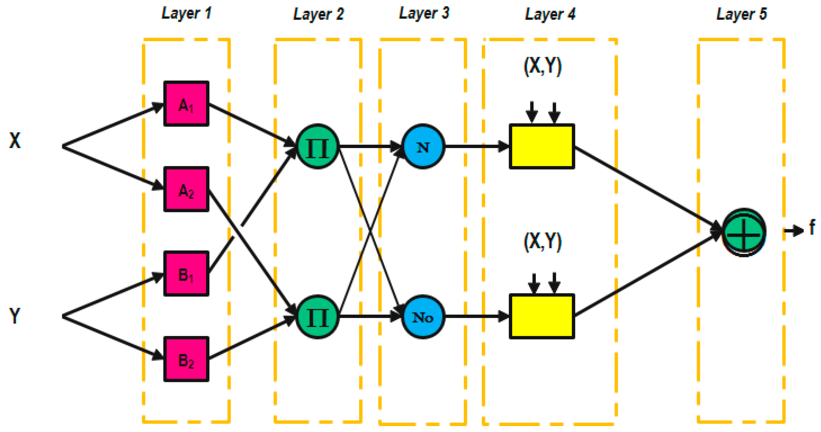
The Takagi–Sugeno fuzzy inference approach is utilized in hybrid systems known as Adaptive Neuro-Fuzzy Inference Systems (ANFIS). Figure 2 illustrates the five layers that form the ANFIS architecture. During the training process, the gradient descent (backpropagation) algorithm is used to optimize the parameters of the premise layer, while the least squares method is applied to identify the consequent parameters and minimize the overall error. For simplicity, a system with a single output (y) and two inputs (x1 and x2) is considered, represented by a Takagi–Sugeno–Kang (TSK) fuzzy model consisting of two rules [32].
if x1 is A1 and x2 is B1 then y1 = f1(x1, x2) = a1x1 + b1x2 + c1
if x1 is A2 and x2 is B2 then y2 = f1(x1, x2) = a2x1 + b2x2 + c2
Jang proposed in [30] a representation of the rule base adaptive network of Figure 2.
The adaptive network ANFIS is a multilayer structure with unweighted connections. Its nodes are categorized into two types according to their functions: square (adaptive) nodes contain parameters, whereas circular (fixed) nodes do not. However, each node, regardless of type, processes incoming signals through a specific function. As shown in Figure 2, all nodes within the same layer use functions belonging to the same functional family, which will be described in detail below. The output O ( i , k ) of node i in layer k (denoted as node (i, k)) depends on the signals from the preceding layer (k − 1) and on the parameters associated with node (i, k), as expressed in Equation (18).
O (i, k) = f (O (1, k − 1)…O (nK − 1, k − 1), a, b, c …).
where n k 1 indicates the quantity of nodes in layer k 1 , and a , b , c , represent the attributes of node ( i , k ) . As for the circular node, these attributes do not apply.
  • Layer 1: Generation of the membership degree:
Each node possesses tunable parameters. The function of the node corresponds to the membership function of a fuzzy subset within the domain of the inputs.
O(i, l) = f(i, l) (x) = ȠAi(x)
where x is the input of node i and Ai the linguistic term associated with its function η A i . In other words, O   ( i , 1 ) is the membership degree of x to A i defined by a membership function η   A i   ( x ) .
  • Layer 2: Rule i generation weight:
The node designated as (pi) is a circular node and represents a Sugeno fuzzy rule. It processes the outputs from the fuzzification nodes and determines its activation. The combination of the antecedents is executed using the product operator.
Wi = ȠAi(x1).ȠBi−2(x2), i = 1…2
  • Layer 3: Rule i normalization weight:
This layer features a circular node referred to as N. At this stage, a specific fuzzy rule is applied to compute the normalized activation level. The value derived signifies the impact of the fuzzy rule’s contribution, which constitutes the final outcome.
V i = W i W 1 + W 2
  • Layer 4: Rules calculation output:
This layer displays a square node performing a function with the subsequent computation.
O(i, 4) = vi.f = vi (aix1 + bix2 + ci)
where vi is the output of layer 3, and {ai, bi, ci} is the set of adjustable output parameters of rule i.
  • Layer 5: ANFIS calculation by sum generation:
It produces the result from ANFIS by adding together the outputs of all the defuzzification nodes.
O   ( i ,   5 ) = y = i v i . f i

4.2. ANFIS Speed Estimator

A novel approach for controlling the speed of induction motors without the use of sensors is presented. Rather than relying on a mechanical sensor, this new technique calculates rotor speed through an adaptive neural fuzzy inference system (ANFIS). The simulation is conducted with MATLAB R2019 software, where ANFIS is acquired using the anfisedit command in the command window, employing a hybrid learning algorithm that combines back propagation with the least squares method. This model delivers excellent outcomes in approximating nonlinear functions.
A novel sensorless control approach for induction motor speed regulation is presented. Instead of employing a mechanical sensor, the proposed method estimates the rotor speed using an Adaptive Neuro-Fuzzy Inference System (ANFIS). The simulations are carried out in MATLAB, where the ANFIS model is created using the anfisedit command. A hybrid learning algorithm combining backpropagation and the least squares method is used for training. This model demonstrates excellent performance in approximating nonlinear functions.
The following steps summarize the procedure for implementing the ANFIS in MATLAB:
  • Select an appropriate set of membership functions.
  • Provide the input–output data required for ANFIS training.
Since speed estimation relies entirely on measurable stator quantities—namely stator currents and voltages—these variables are used as inputs to the ANFIS block. It is important to note that accurate system representation at the modeling stage is crucial for achieving reliable learning outcomes.
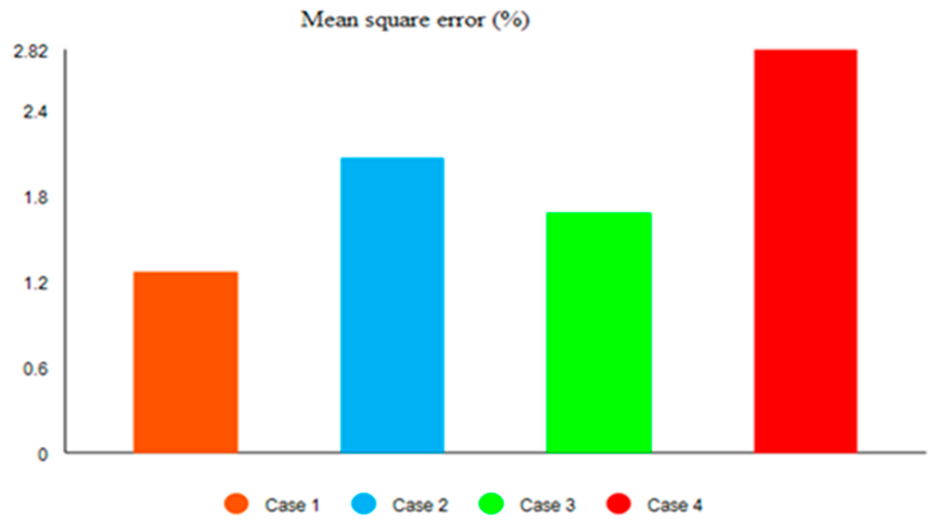
To evaluate the ANFIS configuration, a series of simulations are performed in MATLAB/Simulink by varying both the number and types of membership functions. The optimal configuration is determined based on the Root Mean Square Error (RMSE) obtained during training, the number of rules, and the convergence time. Five types of membership functions are tested to identify the most suitable structure. The RMSE values corresponding to different membership function shapes are summarized in Table 2 and illustrated in Figure 3. The results clearly show that the triangular membership function yields the lowest error, indicating that it provides the most accurate prediction performance.
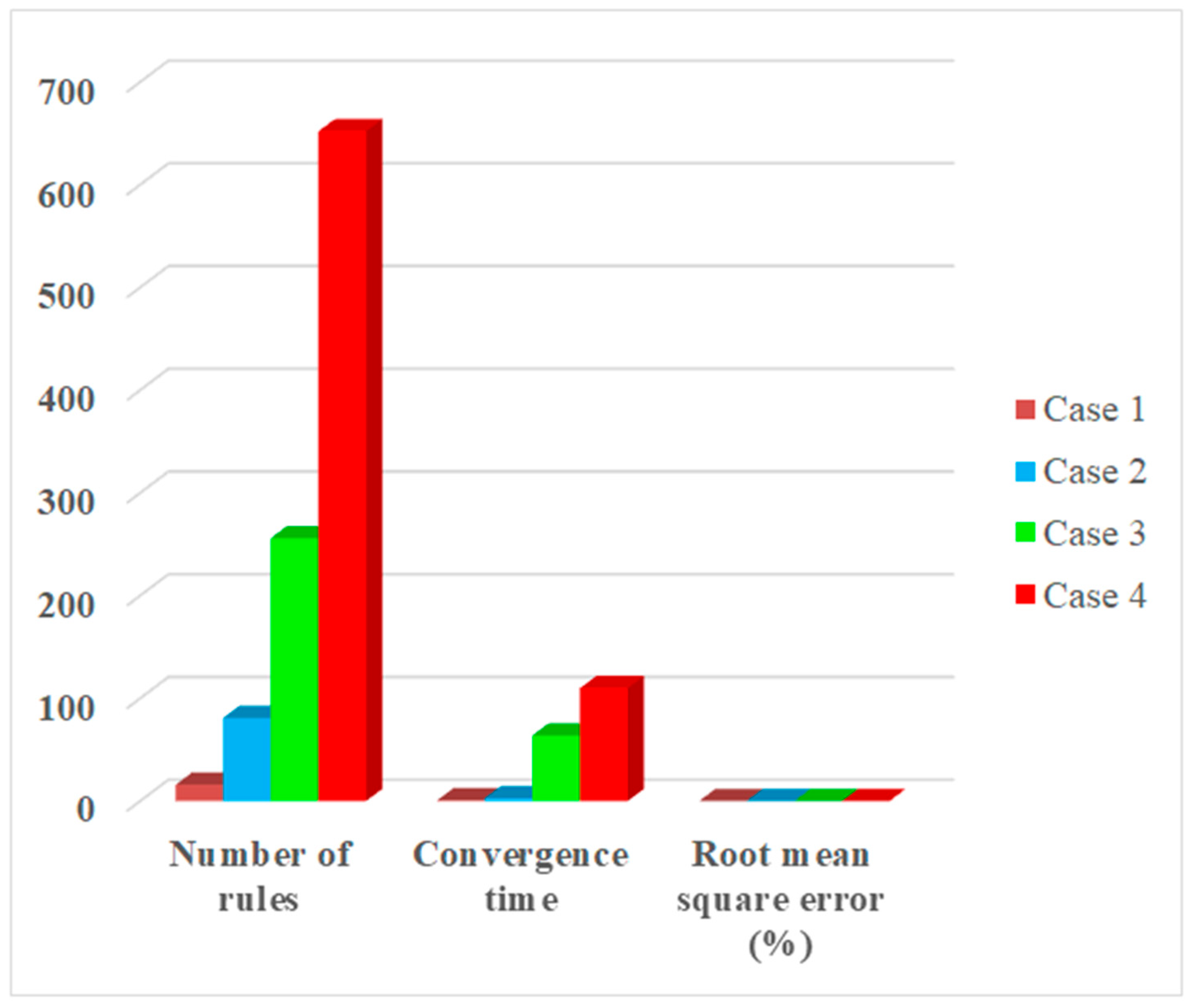
During the evaluation of the ANFIS under different numbers of membership functions, data such as the number of rules, convergence time, and root mean square error (RMSE) during training were collected, as summarized in Table 3 and illustrated in Figure 4. Increasing the number of membership functions enhances prediction accuracy; however, it also leads to a higher number of fuzzy rules, which negatively affects the convergence speed and increases the system’s computational complexity.
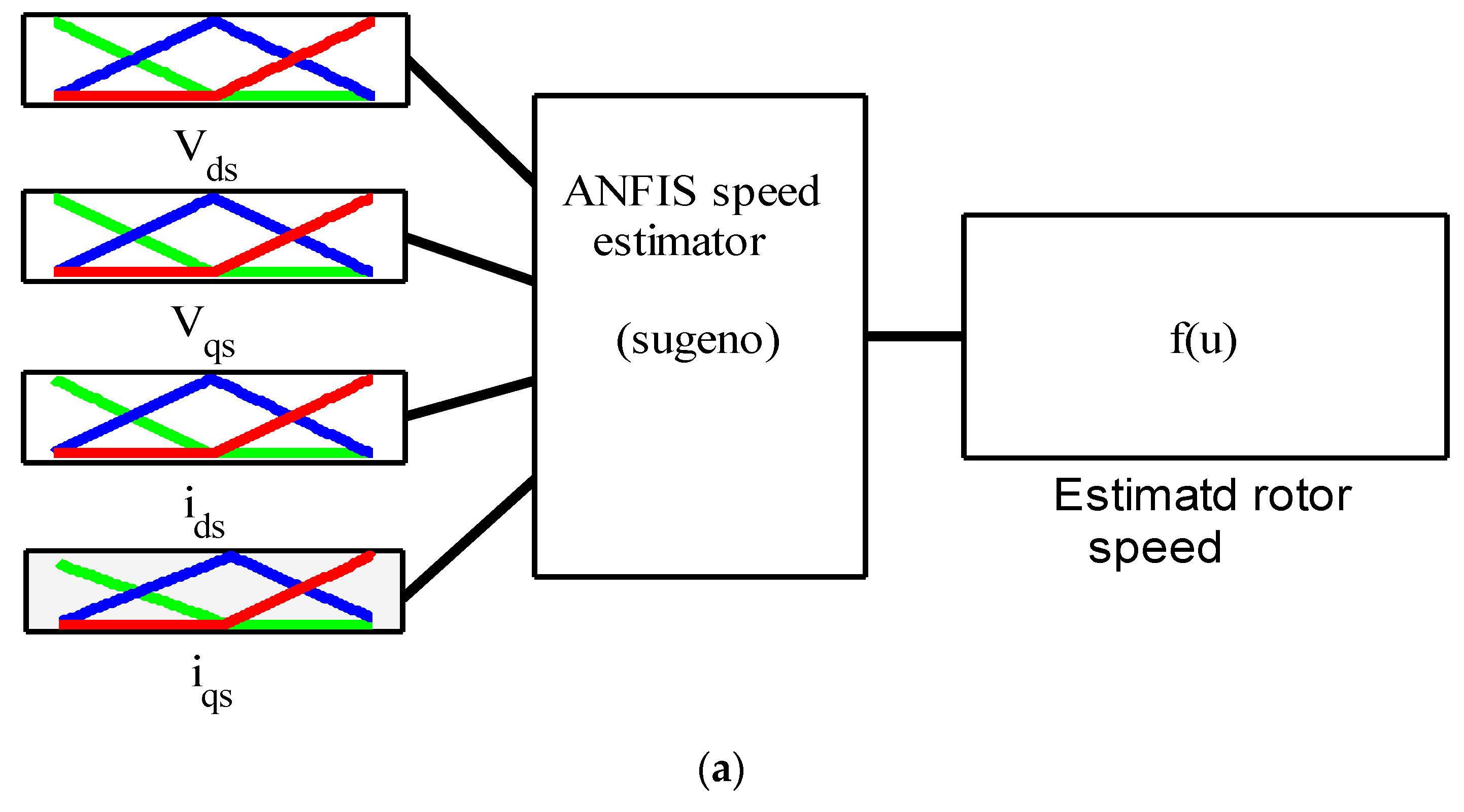
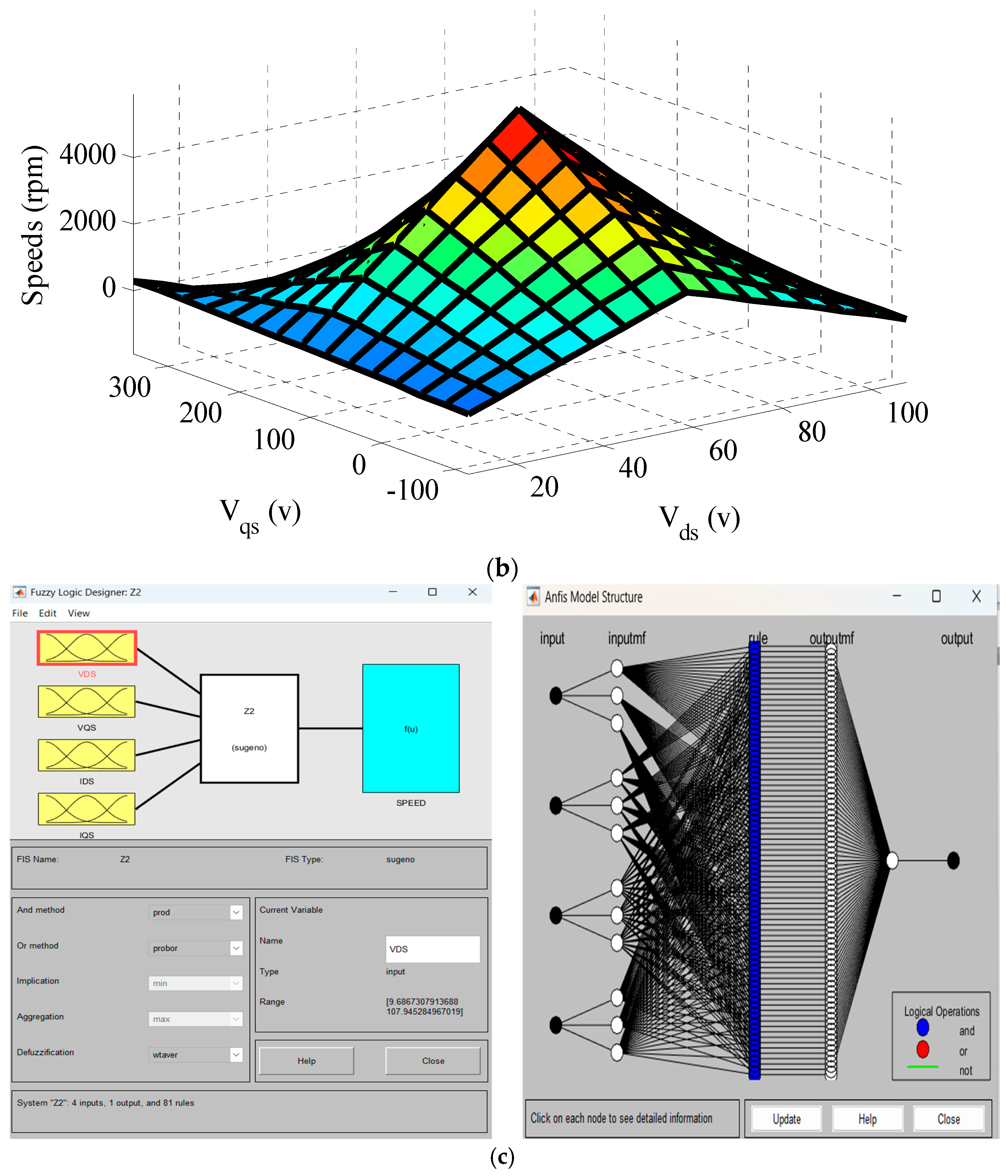
Table 4 outlines the parameters of the optimized ANFIS configuration for rotor speed estimation and Figure 5 illustrates the features of the suggested ANFIS in terms of design and surface view. It presents also parameters of suggested ANFIS. The rules ‘number that is here 81 is generated automatically by ANFIS, it depends on inputs number and membership function and number of membership functions chosen. Here in our study, we have chosen 3 as number of membership functions. Integrated inputs for our ANFIS estimation are stator currents and stator voltages.

4.3. MRAS-Based Luenberger Speed Observer

The mathematical representation of the full order Luenberger observer is outlined in terms of the state and output equations. It is expressed using (24).
x ˙ o t = F   x o t + G   u t + M L o y o t y t y o t = H   x o t
Here, the subscript “o” indicates the measured values. Matrices F , G and H represent the equivalent state space of the three-phase induction motor in the d, q reference frame. The matrix M L o indicates the gain of the full-order Luenberger observer. The vector x o t represents the observed state, while u t denotes the input vector of the system. The vectors y t and y o t refer to the system’s output and its observed value, respectively.
The observed state vector is described as:
x o t = i d s o i q s o Φ d s o Φ q s o Φ d r o Φ q r o T
The input vector is composed of the direct and reverse components of the stator voltage in the d, q reference frame.
u ( t ) = V d s V q s T
The direct and reverse components of the stator current in the d, q reference frame are the two components of the output vector.
y ( t ) = i d s i q s T
The full-order Luenberger observer matrix gain M L o is chosen such that the poles ensure the stability of the matrix F M L o   H .
To estimate the rotor speed, a model reference mechanism is utilized. This mechanism consists of two models. The reference model selected is the voltage model, which is associated with the rotor speed. The full Luenberger observer is chosen as an adjustable model. The speed MRAS estimator is represented by the following mathematical Equation (28).
ω o = G p i d s i d s o Φ q r o + G i i d s i d s o Φ q r o d t
where G p and G i are the proportional and integral coefficients.

4.4. Comparative Study of Performance of Speed Estimators

The performance of the ANFIS speed estimator was compared with three established methods: MRAS-based Luenberger observer, Extended Kalman Filter (EKF), and Sliding Mode Observer (SMO). Similar comparative frameworks have been reported in recent studies on sensorless induction motor control [47,48]. Table 5 summarizes key performance metrics, including root mean square error (RMSE), convergence time, and robustness to load disturbances. The ANFIS estimator achieves the lowest RMSE (0.005 rpm) and fastest convergence (5 s), outperforming MRAS (RMSE: 0.008 rpm, 7 s), EKF (RMSE: 0.010 rpm, 8 s), and SMO (RMSE: 0.012 rpm, 6 s). These results are consistent with previous work demonstrating that ANFIS-based estimators improve dynamic accuracy and robustness in low-speed and field-weakening regions due to their adaptive fuzzy-neural structure [49]. However, this approach requires higher computational resources owing to the large rule base (81 rules for 3 MFs). EKF methods have shown excellent noise-rejection capabilities but remain sensitive to modeling inaccuracies [50], while SMO techniques provide fast response but exhibit chattering under low-speed operation [51]. MRAS-based observers maintain a good trade-off between simplicity and performance but show reduced transient accuracy compared to adaptive neuro-fuzzy systems [52,53]. Overall, simulation results confirm that the proposed ANFIS-based estimator offers the best compromise between accuracy and dynamic performance among the evaluated techniques.

5. NPC Inverter

For multi-level inverters, which have various applications and significantly affect multiple sectors of electrical engineering, the advancement of power electronics is essential. The three-level inverter has essentially become a standard product. Multi-level inverter technology is now a prominent research area, and new topologies have emerged recently at both academic and industrial levels. NPC inverter technology is predominantly employed in these topologies [3,4,6]. The most prevalent multi-level inverter configurations and their conventional SVM control techniques are demonstrated below.

5.1. NPC Topology

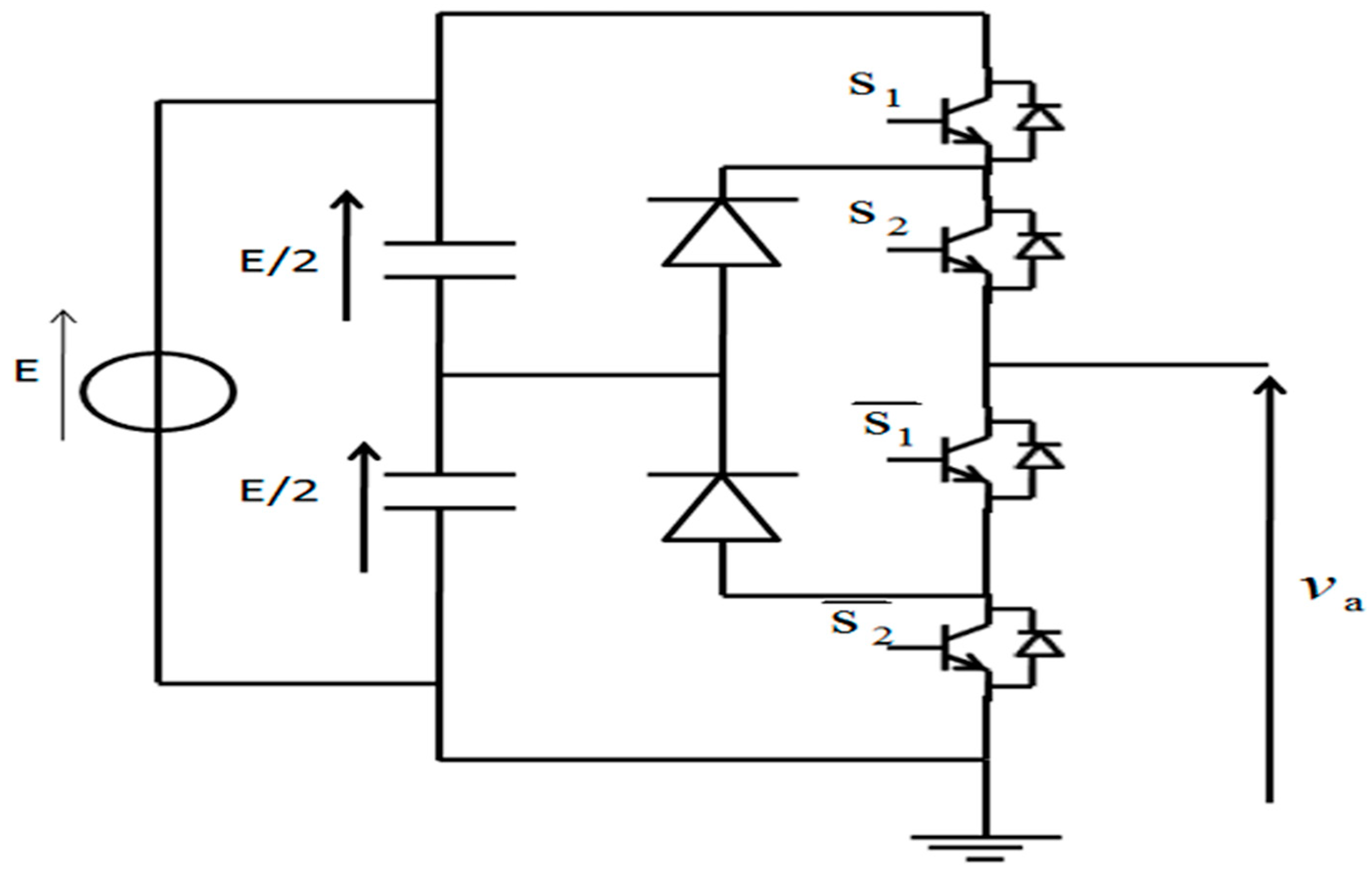
NPC three-level inverters, as presented in Figure 6, are popular in both academia and industry due to their attractive characteristics, simple design, and control system. Additionally, the NPC three-level inverter features decreased output current ripple and common-mode voltage. We certainly utilize the same switching frequency as a two-level inverter.

5.2. SVM Topology

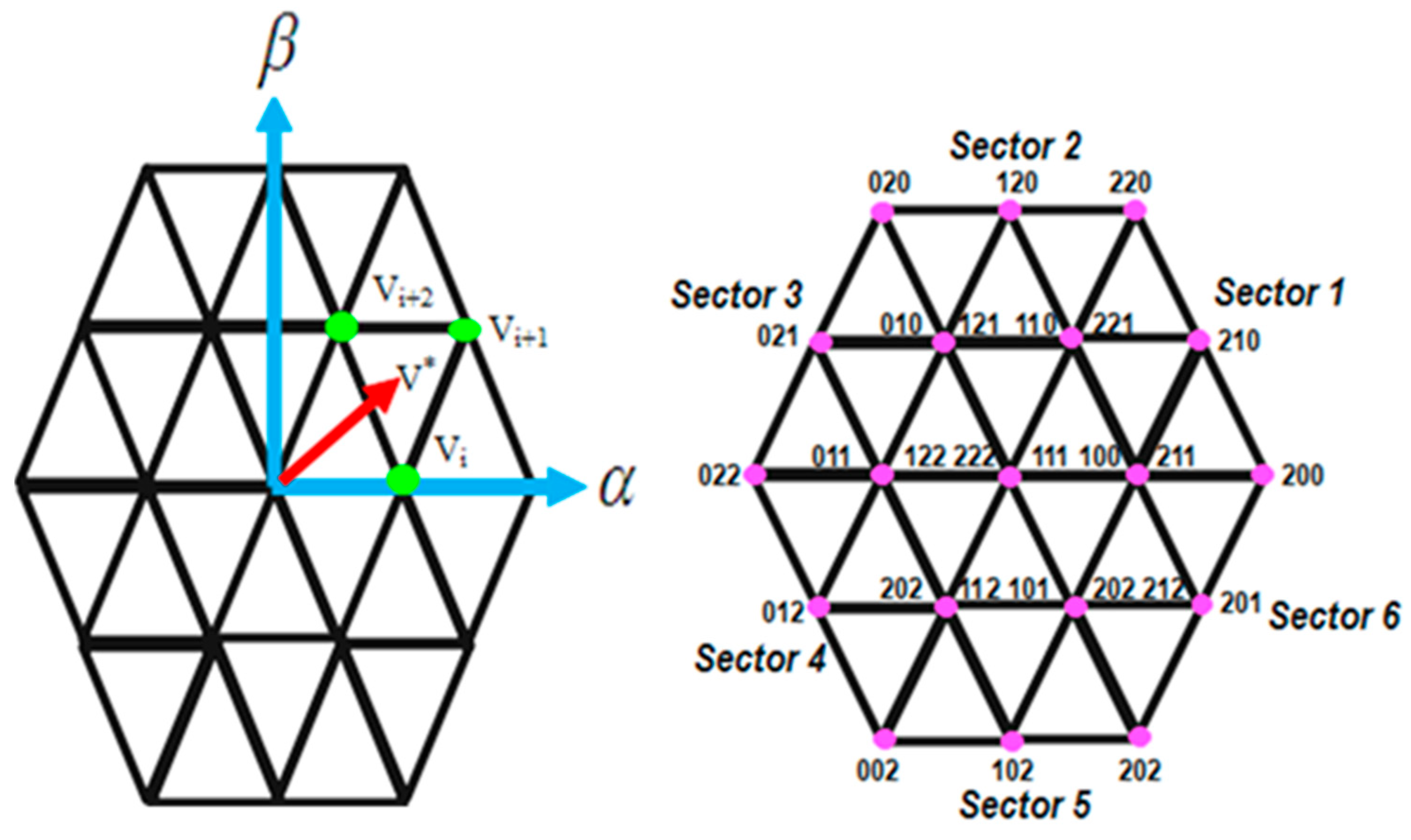
Three-level inverters can be controlled using the space vector modulation (SVM) method. This technique generates a signal with variable pulse width and is readily adaptable to all types of multilevel inverters. The primary advantages of SVM include low current ripple, efficient utilization of the DC-link voltage, and straightforward implementation using a digital signal processor (DSP). These features make it particularly suitable for high-voltage power applications. Figure 7 illustrates the space vectors for three-level inverters; these vector diagrams are universally applicable, irrespective of the multilevel inverter topology [12]. By calculating the duty cycles for each of the three adjacent vectors (Vi, Vi+1, and Vi+2), a desired reference voltage vector can be synthesized.
A three-level NPC inverter with three-phase output, where each of the three legs is depicted in Figure 6, comprises twelve switching cells, with four switches per leg. During each modulation cycle of the inverter, the two-phase voltages derived from the control algorithm can be represented in a fixed frame through their respective projections. This allows for the control of just a two-phase vector. The transformation matrix is
V s α V s β = 3 2 1 1 2 1 2 0 3 2 3 2 V a n V b n V c n
The various switching conditions of the inverter’s three arms, the voltages between different points of a three-level inverter, and the voltages in the (d,q) reference frame are shown in Table 6.

6. Results and Discussion

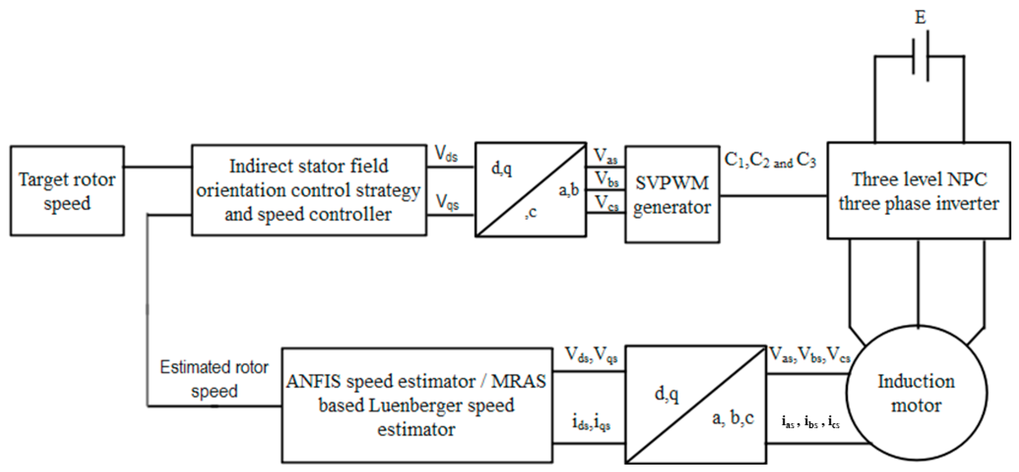
The system’s performance was validated through comprehensive simulations performed in MATLAB/Simulink. Figure 8 shows the detailed simulation model, which includes an induction motor, a three-level neutral–point–clamped (NPC) inverter, an ANFIS estimator, and the indirect stator flux orientation control (ISFOC) module. The space vector modulation (SVM) technique is implemented in the three-level NPC inverter module.
The performance of the sensorless ISFOC system for three-phase induction motors, driven by SVM, was evaluated under various speed and load conditions. Simulations were run over a 10 s period to verify the drive’s capability. The method was tested across a broad speed range, including field weakening, standstill, and forward/reverse operation, both with and without load. The simulation began under no-load conditions until t = 4.5 s. Various speed profiles were then tested, covering variable speeds with field weakening, zero speed, and bidirectional operation. In detail, the reference speed was held at zero from t = 0 to 1 s. From t = 1 to 2 s, it ramped up linearly at 1910 rpm/s to a constant 1910 rpm. It then increased linearly at the same rate from t = 2 to 3.5 s, reaching a constant 2890 rpm by t = 3.5 s, which was maintained until t = 5 s. A 6-Nm load was applied at t = 4.5 s. From t = 5 to 6 s, the reference speed decreased at 1000 rpm/s to enter reverse operation at −1000 rpm, with the load unchanged. Finally, from t = 6 to 8 s, the speed ramped back to standstill at t = 8 s and remained at zero thereafter.
The simulation results are shown in Figure 9, Figure 10, Figure 11, Figure 12 and Figure 13. The d- and q-axis stator flux responses indicate effective decoupling of the three-phase induction motor across all speed ranges, including high speeds. High-speed operation requires large input voltages. In practice, inverter voltage limits require flux reduction below its rated value once speed exceeds the nominal value—this is field weakening. Accordingly, the flux magnitude follows its reference closely below rated speed but decreases as motor speed increases further. The flux trajectory in the α–β plane appears in Figure 10.
Figure 9 shows the ANFIS-estimated speed, MRAS-based Luenberger-estimated rotor speed, reference speed, and estimation errors. The ANFIS rotor speed estimator performs well, with estimates closely matching the actual speed. The MRAS-based Luenberger observer shows slightly higher estimation error than the ANFIS estimator across all conditions, including motoring/generating modes, bidirectional operation, and constant/variable speeds. The ANFIS estimator also tracks the actual speed accurately and quickly during load application, confirming its robustness to load disturbances.
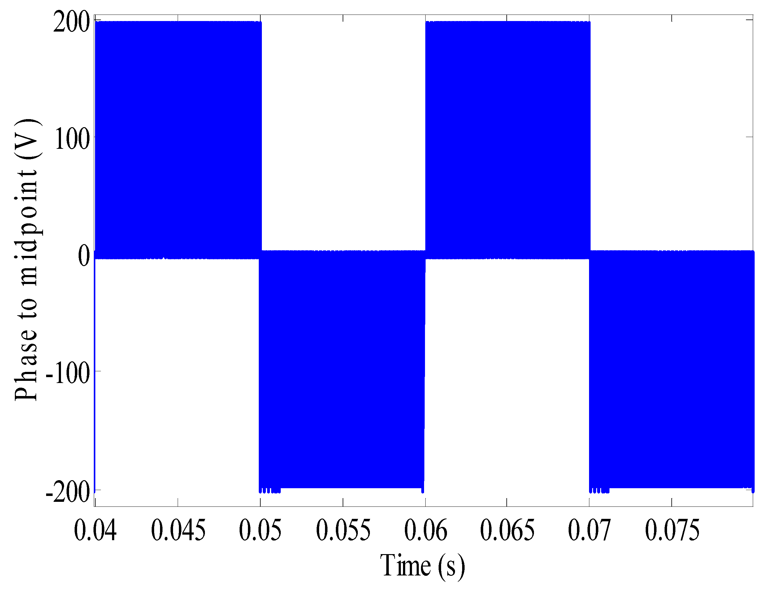
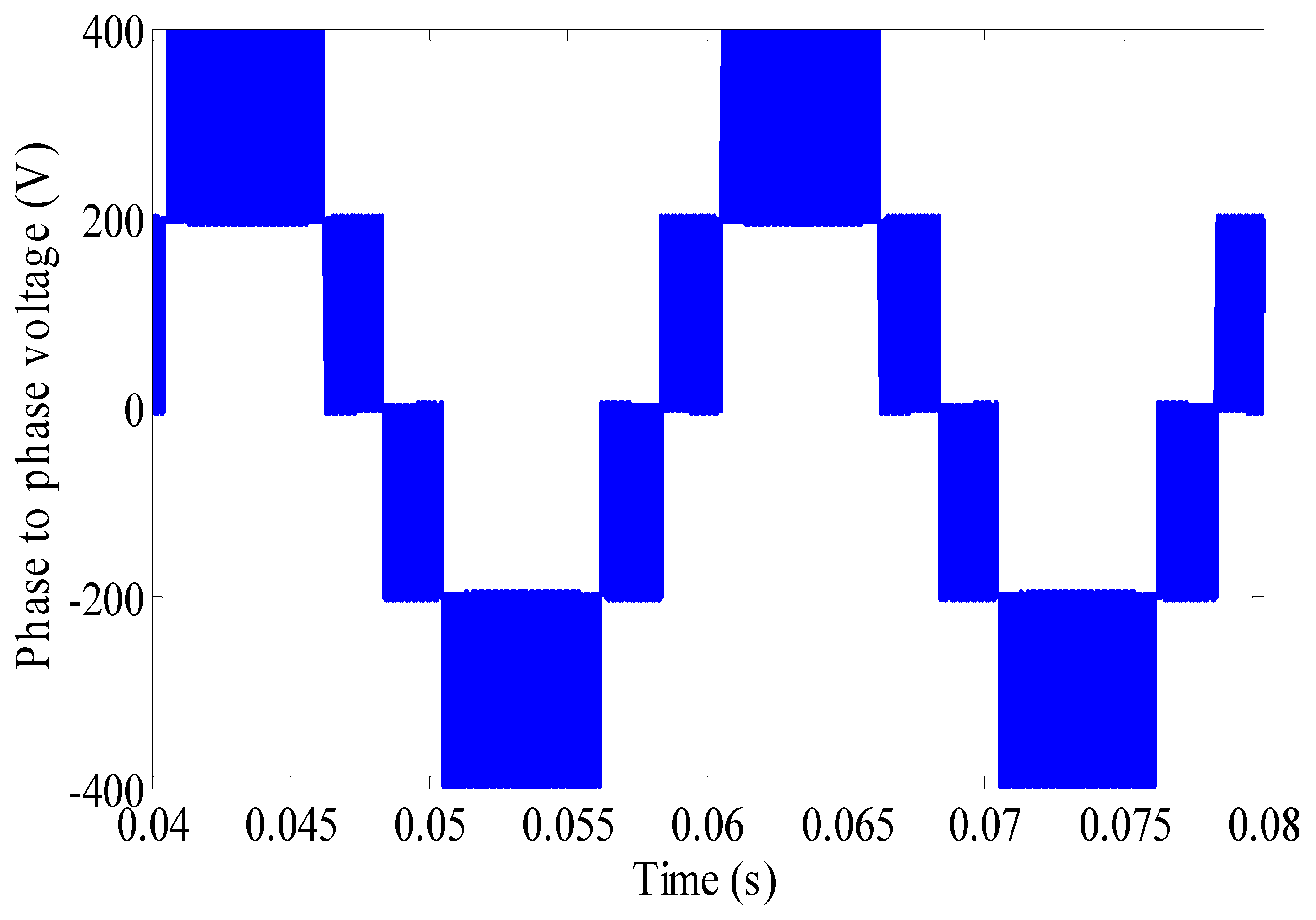
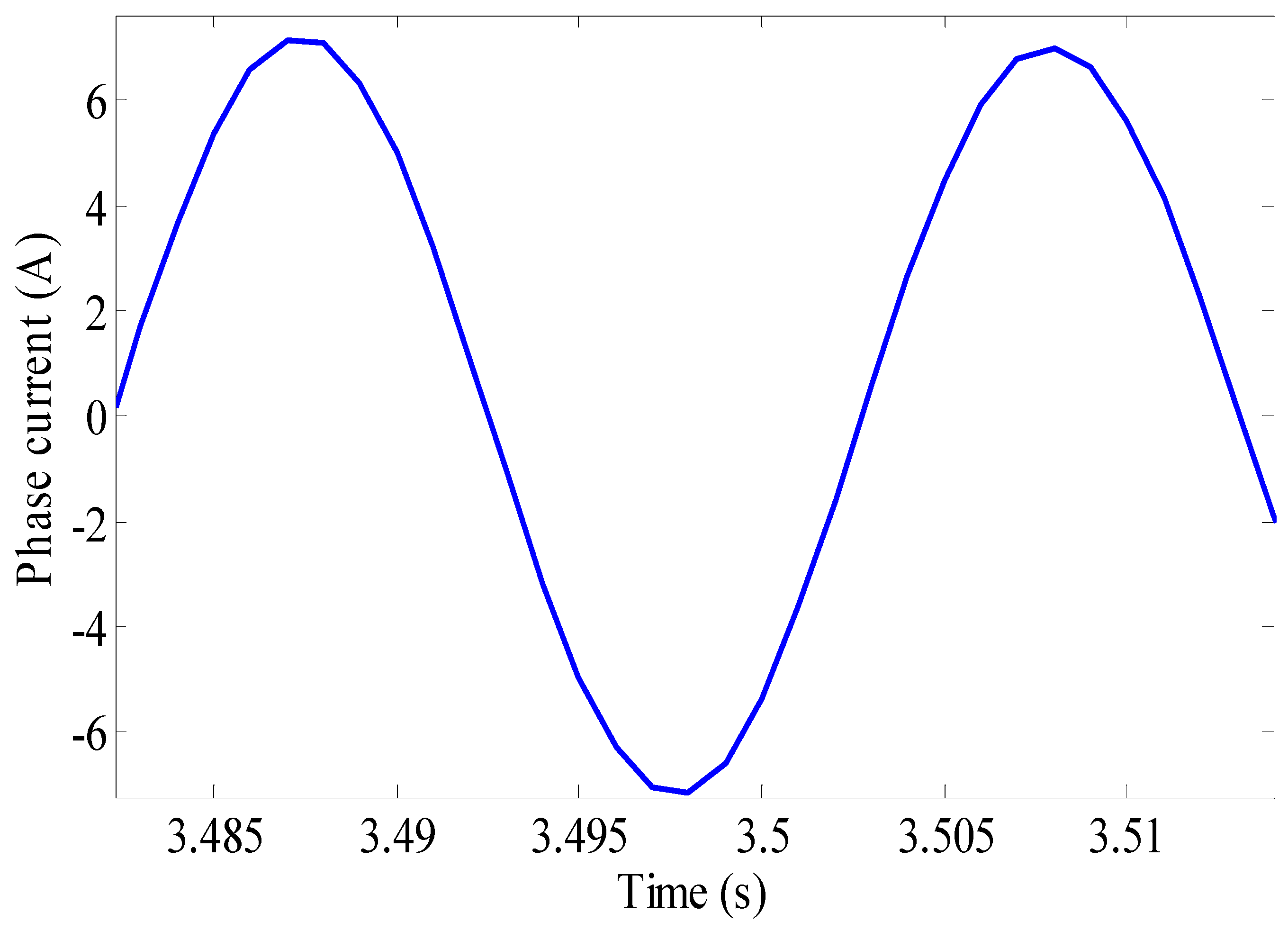
Figure 11 and Figure 12 display the line-to-neutral and line-to-line voltage waveforms, respectively, produced by SVM. The line-to-neutral voltage has three distinct levels, with the inverter passing through the zero state between positive and negative states. The line-to-line voltage has five levels, verifying proper operation of the SVM-controlled three-level NPC inverter. As seen in the voltage and current waveforms of Figure 12, the three-level NPC inverter produces lower harmonic distortion than a two-level inverter, especially for the 5th, 7th, and 11th harmonics. This stems from its ability to generate output voltages with more discrete levels, resulting in a more sinusoidal waveform. The NPC topology uses a clamping circuit to create a neutral point at the DC-bus midpoint, allowing three output voltage levels instead of two. As a result, the SVM technique lowers stator current harmonic distortion and torque ripple, leading to smoother motor operation, reduced mechanical stress, and improved overall system performance. Careful selection of voltage vectors also reduces switching losses, boosting output voltage and efficiency.

7. Conclusions

The proposed model enhances ISFOC for induction motors driven by a three-level NPC inverter with SVM. Unlike conventional approaches based on IFOC or DTC, our method improves IM control by decoupling flux and torque while avoiding the complexity of direct machine parameter tuning. Simulation results further underscore the benefits of the three-level NPC inverter with SVM, the most established combination of topology and modulation strategy, rendering it ideal for asynchronous machines. The ANFIS estimator also yields reliable results, serving as an effective sensorless alternative by estimating speed from measurable stator quantities (voltages and currents) alone. This confirms the value of hybrid AI techniques combining fuzzy inference and neural networks.
As a future direction, we anticipate extending the ANFIS model to electric vehicle (EV) applications and advanced schemes such as DTC. For effective EV deployment, the training dataset must account for typical dynamics, including rapid acceleration, frequent start-stop cycles, and regenerative braking, which require high responsiveness and accuracy. Given EVs’ energy constraints, subsequent work should prioritize efficiency and consumption optimization. Another avenue involves replacing the NPC inverter with EV-suited topologies, such as multiphase or interleaved bridges, potentially altering the control model’s structure and parameters. Finally, integrating our ANFIS approach with emerging strategies like DTC or predictive control (widely used in EV traction) promises further enhancements in real-world performance.

Author Contributions

Conceptualization, Z.B. and B.O.; methodology, Z.B.; software, Z.B. and B.O.; validation, B.O. and M.B.H.; formal analysis, Z.B.; investigation, Z.B. and B.O.; resources, Z.B.; data curation, Z.B.; writing—original draft preparation, Z.B.; writing—review and editing, B.O.; visualization, B.O.; supervision, M.B.H.; project administration, M.B.H. All authors have read and agreed to the published version of the manuscript.

Funding

This research received no external funding.

Data Availability Statement

All data available regarding this study are shared in this paper.

Acknowledgments

Authors wish to express sincere gratitude to Tarek Bouzayeni for his generous support, which made this research possible. His contribution is gratefully acknowledged and deeply appreciated.

Conflicts of Interest

The authors declare no conflicts of interest.

References

  1. Tounsi, M.M.; Allali, A.; Boulouiha, H.M.; Denaï, M. ANFIS control of a shunt active filter based with a five-level NPC inverter to improve power quality. Int. J. Electr. Comput. Eng. (IJECE) 2021, 11, 1886–1893. [Google Scholar] [CrossRef]
  2. Vargas, O.S.; Aldaco, S.E.D.L.; Alquicira, J.A.; Vela-Valdés, L.G.; Núñez, A.R.L. Adaptive network-based fuzzy inference system (ANFIS) applied to inverters: A survey. IEEE Trans. Power Electron. 2023, 39, 869–884. [Google Scholar] [CrossRef]
  3. Karaboga, D.; Kaya, E. Adaptive network based fuzzy inference system (ANFIS) training approaches: A comprehensive survey. Artif. Intell. Rev. 2019, 52, 2263–2293. [Google Scholar] [CrossRef]
  4. Anjan Kumar, S. A novel metaheuristic approach for simultaneous loss minimization and torque ripple reduction of DTC-IM driven EV. Green Energy Intell. Transp. 2025, 4, 1–10. [Google Scholar]
  5. Lin, S.; Jian, Z.; Kai, C.; Xuhui, W. A Static Current Error Elimination Algorithm for Predictive Current Control in PMSM for Electric Vehicles. Green Energy Intell. Transp. 2025, 100306. [Google Scholar] [CrossRef]
  6. Jenkal, H.; Bossoufi, B.; Boulezhar, A.; Lilane, A.; Hariss, S. Vector control of a Doubly Fed Induction Generator wind turbine. Mater. Today Proc. 2020, 30, 976–980. [Google Scholar] [CrossRef]
  7. Dyanamina, G.; Kakodia, S.K. Adaptive neuro fuzzy inference system based decoupled control for neutral point clamped multi-level inverter fed induction motor drive. Chin. J. Electr. Eng. 2021, 7, 70–82. [Google Scholar] [CrossRef]
  8. Boussada, Z.; Elbeji, O.; Benhamed, M. Different topologies and control techniques of multi-level inverter: A literature survey. In Proceedings of the 2017 International Conference on Green Energy Conversion Systems (GECS), Hammamet, Tunisia, 23–25 March 2017; IEEE: New York, NY, USA, 2017; pp. 1–5. [Google Scholar]
  9. Ramprasad, A.; Giribabu, D.; Kakodia, S.K.; Panda, A.K. Performance analysis of three-level NPC inverter Fed PMSM drives. In Proceedings of the 2022 IEEE International Students’ Conference on Electrical, Electronics and Computer Science (SCEECS), Bhopal, India, 19–20 February 2022; IEEE: New York, NY, USA, 2022; pp. 1–6. [Google Scholar]
  10. Baschera, N.E.L.; Di Benedetto, M.; Lidozzi, A.; Solero, L. FPGA Based Space Vector Modulation Strategy for the Three-Phase 7-Level Multiplexed Converter. In Proceedings of the 2024 IEEE Energy Conversion Congress and Exposition (ECCE), Phoenix, AZ, USA, 20–24 October 2024; IEEE: New York, NY, USA, 2024; pp. 3405–3412. [Google Scholar]
  11. Younes, D.; El Mehdi, A.S.A.; Houcine, C.; Mouloud, D. Sensorless Torque Control of an Electric Vehicle Driven by an Open End Winding Induction Motor: An Experimental Study. In Proceedings of the 2023 Second International Conference on Energy Transition and Security (ICETS), Adrar, Algeria, 12–14 December 2023; IEEE: New York, NY, USA, 2023; pp. 1–6. [Google Scholar]
  12. Pabbewar, A.S.; Kowsalya, M. Three level neutral point clamped inverter using space vector modulation with proportional resonant controller. Energy Procedia 2016, 103, 286–291. [Google Scholar] [CrossRef]
  13. Chandrasekaran, S.; Durairaj, S.; Padmavathi, S. A performance improvement of the fuzzy controller-based multi-level inverter-fed three-phase induction motor with enhanced time and speed of response. J. Electr. Eng. Technol. 2021, 16, 1131–1141. [Google Scholar] [CrossRef]
  14. Homaeinezhad, M.; Beik, O. Development of a Generalized Multilevel SVM and Capacitor Voltage Balancing Strategy for Multiphase Three-Level NPC Converters. IEEE Open J. Power Electron. 2024, 5, 1059–1070. [Google Scholar] [CrossRef]
  15. Balal, A.; Dinkhah, S.; Shahabi, F.; Herrera, M.; Chuang, Y.L. A review on multilevel inverter topologies. Emerg. Sci. J. 2022, 6, 185–200. [Google Scholar] [CrossRef]
  16. Kanaujia, A.K.; Kumar, S. A Novel Multi-Level SVPWM Scheme for High Power Induction Motor Drive Applications. In Proceedings of the IEEE 1st International Conference on Smart and Sustainable Developments in Electrical Engineering (SSDEE), Dhanbad, India, 28 February–2 March 2025; pp. 1–7. [Google Scholar]
  17. Elbeji, O.; Boussada, Z.; Ben Hamed, M. Inverter control: Comparative study between SVM and PWM. In Proceedings of the 2017 International Conference on Green Energy Conversion Systems (GECS), Hammamet, Tunisia, 23–25 March 2017; IEEE: New York, NY, USA, 2017; pp. 1–6. [Google Scholar]
  18. Benbouhenni, H.; Bizon, N. A new direct power control method of the DFIG-DRWT system using neural PI controllers and four-level neural modified SVM technique. J. Appl. Res. Technol. 2023, 21, 36–55. [Google Scholar] [CrossRef]
  19. Oukassi, A.; Elamri, O.; Boulghasoul, Z. ADRC and IFOC Control of a Sensorless Induction Motor Driven by a Multilevel Converter Using SVM Approach and PV Generators. Math. Probl. Eng. 2024, 2024, 6183332. [Google Scholar] [CrossRef]
  20. Beniak, R.; Górecki, K.; Rogowski, K. Real-Time Switching Number Reduction SVM for a Two-Phase Motor Powered by Three-Level NPC Inverter. Energies 2023, 16, 749. [Google Scholar] [CrossRef]
  21. Khamlich, S.; Khamlich, F.; Atouf, I.; Benrabh, M. Performance evaluation and implementations of MFCC, SVM and MLP algorithms in the FPGA board. Int. J. Electr. Comput. Eng. Syst. 2021, 12, 139–153. [Google Scholar] [CrossRef]
  22. Govindharaj, I.; Rampriya, R.; Balamurugan, S. Improving robustness and dynamic performance of sensorless vector-controlled IM drives with ANFIS-enhanced MRAS. Int. J. Electr. Electron. Res. 2024, 12, 975–980. [Google Scholar]
  23. Korzonek, M.; Orlowska-Kowalska, T. Discrete implementation of sensorless IM drive with MRAS-type speed estimator. In Proceedings of the 2019 International Conference on Electrical Drives & Power Electronics (EDPE), The High Tatras, Slovakia, 24–26 September 2019; pp. 242–247. [Google Scholar]
  24. Ammar, A.; Kheldoun, A.; Metidji, B.; Ameid, T.; Azzoug, Y. Feedback linearization based sensorless direct torque control using stator flux MRAS-sliding mode observer for induction motor drive. SA Trans. 2020, 98, 382–392. [Google Scholar] [CrossRef]
  25. Misra, P.; Kumar, B. Rotor resistance estimation for improved performance of MRAS-based sensorless speed estimation of induction motor drives. In Intelligent Algorithms for Analysis and Control of Dynamical Systems; Springer: Berlin/Heidelberg, Germany, 2021; pp. 177–187. [Google Scholar]
  26. Korzonek, M.; Tarchala, G.; Orlowska-Kowalska, T. A review on MRAS-type speed estimators for reliable and efficient induction motor drives. ISA Trans. 2019, 93, 1–13. [Google Scholar] [CrossRef]
  27. Karlovsky, P.; Lipcak, O.; Lettl, J. Estimation of stator voltage of inverter-supplied induction motor using Kalman Filter. In AETA 2019; Springer: Berlin/Heidelberg, Germany, 2021; pp. 64–73. [Google Scholar]
  28. Banu, S.; Johnson, T.; Moger, T. A comparative analysis of speed estimation techniques of induction motor drive using non-linear Kalman Filters. In Proceedings of the 2021 31st Australasian Universities Power Engineering Conference (AUPEC), Online, 26–30 September 2021; pp. 1–6. [Google Scholar]
  29. Quan, V.; Long, T. Sensorless sliding mode control method for a three-phase induction motor. Electr. Eng. 2022, 104, 3685–3695. [Google Scholar] [CrossRef]
  30. Ilten, E.; Demirtas, M. Fractional order super-twisting sliding mode observer for sensorless control of induction motor. COMPEL—Int. J. Comput. Math. Electr. Electron. Eng. 2019, 38, 878–892. [Google Scholar] [CrossRef]
  31. Mansouri, S.A.; Ahmarinejad, A.; Javadi, M.S.; Heidari, R.; Catalão, J.P.S. Improved double-surface sliding mode observer for flux and speed estimation of induction motors. ET Electr. Power Appl. 2020, 14, 1002–1010. [Google Scholar] [CrossRef]
  32. El Daoudi, S.; Lazrak, L.; Lafkih, M.A. Sliding mode approach applied to sensorless direct torque control of cage asynchronous motor via multi-level inverter. Prot. Control Mod. Power Syst. 2020, 5, 13. [Google Scholar] [CrossRef]
  33. Feng, F.; Yang, J.; Hu, H.; Liang, J.; Yu, S. Speed-sensorless model predictive thrust control of linear induction motor based on improved extended Kalman filter observer. Trans. Inst. Meas. Control 2025, 10, 01423312241307713. [Google Scholar] [CrossRef]
  34. Caramori, G.; Oliani, I.; Lunardi, A.S.; Sguarezi Filho, A.J. Robust Predictive Current Control of IMs with MRAS-Based Parameter Estimation. IEEE Access 2025, 13, 90921–90931. [Google Scholar] [CrossRef]
  35. Sengamalai, U.; Anbazhagan, G.; Thentral, T.M.T.; Vishnuram, P.; Khurshaid, T.; Kamel, S. Three phase induction motor drive: A systematic review on dynamic modeling, parameter estimation, and control schemes. Energies 2022, 15, 8260. [Google Scholar] [CrossRef]
  36. Savarapu, S.; Qutubuddin, M.; Narri, Y. Modified brain emotional controller-based ripple minimization for SVM-DTC of sensorless induction motor drive. IEEE Access 2022, 10, 40872–40887. [Google Scholar] [CrossRef]
  37. Hasan, F. Vector Control of the Induction Motor Based on Whale Optimization Algorithm. Int. J. Electr. Comput. Eng. Syst. 2025, 16, 31–37. [Google Scholar] [CrossRef]
  38. Govindharaj, I.; Dinesh Kumar, K.; Balamurugan, S.; Yazhinian, S.; Anandh, R.; Rampriya, R.; Karthick, G.; Michael, G. Sensorless vector-controlled induction motor drives: Boosting performance with Adaptive Neuro-Fuzzy Inference System integrated augmented Model Reference Adaptive System. MethodsX 2024, 13, 102992. [Google Scholar]
  39. Abdullah, Q.; Farah, N.; Ahmed, M.S.; Shah, N.S.M.; Aydoğdu, Ö.; Talib, H.N.; Al-Moliki, Y.M.; Uğurenver, A.; Al-Mekhalfi, M.A.A.; Aihsan, M.Z.; et al. Sensorless Speed Control of Induction Motor Drives Using Reinforcement Learning and Self-Tuning Simplified Fuzzy Logic Controller. IEEE Access 2024, 12, 136485–136501. [Google Scholar] [CrossRef]
  40. Benayad, N.; Aouiche, A.; Djeddi, A. Fuzzy Logic Speed Controller for Dual Stator Induction Motor Based on Indirect Vector Control. IAM 2023, 3694, 126–135. [Google Scholar]
  41. Ben Regaya, C.; Farhani, F.; Hamdi, H.; Zaafouri, A.; Chaari, A. Robust ANFIS vector control of induction motor drive for high-performance speed control supplied by a photovoltaic generator. WSEAS Trans. Syst. Control. 2020, 15, 356–365. [Google Scholar] [CrossRef]
  42. Fahassa, C.; Akherraz, M.; Zahraoui, Y. ANFIS speed controller and intelligent dual observer based DTC of an induction motor. In Proceedings of the 2018 International Symposium on Advanced Electrical and Communication Technologies (ISAECT), Rabat-Kenitra, Morocco, 21–23 November 2018; IEEE: New York, NY, USA, 2018; pp. 1–6. [Google Scholar]
  43. Kamaleshwar, R.; Prahadeeshwaran, A.; Srivats Athindran, N. Sensorless sliding mode control SVPWM fed induction motor drive using DSS speed estimator. In Proceedings of the 2017 International Conference on Innovative Research in Electrical Sciences (IICIRES), Nagapattinam, India, 16–17 June 2017; pp. 1–6. [Google Scholar]
  44. Hasan, M.M. Artificial neural network based speed estimator for sensorless field oriented control of three phase induction motor. In Proceedings of the 3rd International Conference on Electrical, Computer & Telecommunication Engineering (ICECTE), Rajshahi, Bangladesh, 26–28 December 2019; pp. 57–60. [Google Scholar]
  45. Reddy, S.; Kumar, B.; Swaroop, D. Investigations on training algorithms for neural networks based flux estimator used in speed estimation of induction motor. In Proceedings of the 6th International Conference on Signal Processing and Integrated Networks (SPIN), Noida, India, 7–8 March 2019; pp. 1090–1094. [Google Scholar]
  46. Omri, B. Software method versus hardware method to balance capacitors voltages for three level NPC converter. In Proceedings of the 2017 International Conference on Green Energy Conversion Systems (GECS), Hammamet, Tunisia, 23–25 March 2017; IEEE: New York, NY, USA, 2017; pp. 1–4. [Google Scholar]
  47. Purwanto, E.; Ferdiansyah, I.; Nugraha, S.D.; Qudsi, O.A. The effect of ANFIS controller on the performance of induction motor drives in low-speed operation based on IFOC. Int. J. Adv. Sci. Eng. Inf. Technol. 2021, 11, 440–450. [Google Scholar] [CrossRef]
  48. Soni, S.K.; Khemariya, M.; Singh, A. Sensorless speed control of induction machine with adaptive-neuro fuzzy technique integrated MRAS module. Int. J. Eng. Trends Technol. 2022, 70, 405–413. [Google Scholar] [CrossRef]
  49. Ramdani, D.R.; Windarko, N.A.; Purwanto, E. Sensorless speed estimation of induction motor using ANFIS. J. Inf. Syst. Eng. Manage. 2025, 10. [Google Scholar] [CrossRef]
  50. Miloud, I.; Cauet, S.; Etien, E.; Salameh, J.P.; Ungerer, A. Real-time speed estimation for an induction motor: An automated tuning of an extended Kalman filter using voltage–current sensors. Sensors 2024, 24, 1744. [Google Scholar] [CrossRef]
  51. Çavuş, B.; Aktaş, M. Sliding mode speed estimation of induction motor with MPC-based flux weakening control for electric vehicle. Afyon Kocatepe Univ. J. Sci. Eng. 2024, 24, 1403–1411. [Google Scholar] [CrossRef]
  52. Hamdi, W.; Hammoudi, M.Y.; Betka, A. Sensorless speed control of induction motor using Model Reference Adaptive System and deadbeat regulator. Eng. Proc. 2023, 56, 16. [Google Scholar]
  53. Zaky, M.S.; Metwaly, M.K. Sensitivity analysis of a stator current-based MRAS estimator for sensorless induction motor drives. Eng. Technol. Appl. Sci. Res. 2024, 14, 17584–17590. [Google Scholar] [CrossRef]
Figure 1. ISFOC Philosophy.
Symmetry 17 01996 g001
Figure 2. ANFIS structure of 2-input Sugeno fuzzy model with 2 rules.
Symmetry 17 01996 g002
Figure 3. Comparative analysis of Mean square error of ANFIS speed estimator under variation in the membership functions number.
Symmetry 17 01996 g003
Figure 4. Comparative analysis of ANFIS speed estimator under variation in the membership functions number.
Symmetry 17 01996 g004
Figure 5. ANFIS speed estimator model: (a) overall shape of ANFIS structure and membership performance for each input parameter; (b) ANFIS surface viewer; (c) suggested ANFIS parameters.
Symmetry 17 01996 g005aSymmetry 17 01996 g005b
Figure 6. Three-level NPC inverter one leg.
Symmetry 17 01996 g006
Figure 7. SVM diagram for three-level NPC inverter.
Symmetry 17 01996 g007
Figure 8. Overall scheme used for Matlab simulation.
Symmetry 17 01996 g008
Figure 9. Estimated speed response.
Symmetry 17 01996 g009
Figure 10. D-axis and Q-axis flux FDS and FQS.
Symmetry 17 01996 g010
Figure 11. Phase to midpoint voltage of the inverter controlled by SVM.
Symmetry 17 01996 g011
Figure 12. Phase to phase voltage of the inverter controlled by SVM.
Symmetry 17 01996 g012
Figure 13. Phase current of the inverter controlled by SVM.
Symmetry 17 01996 g013
Table 1. Induction Motor Parameters.
ParameterDesign
Vds and Vqsd-q axis stator voltages respectively
Ids, Iqs, Idr, and Iqrd-q axis stator currents d-q axis rotor currents respectively
Rs, RrStator and rotor resistance per phase respectively
pNumber of poles
ωs, ωrSpeed of the rotating magnetic field and the rotor speed respectively
CeElectromagnetic developed torque.
Ls, Lr, MSelf-inductances of the stator and rotor and the mutual inductance respectively
Table 2. Mean square error under different types of membership functions.
NoType of Membership FunctionRoot Mean Square Error (%)
1Trimf1.27
2Trapmf2.06
3Gbellmf1.681
4Gaussmf2.82
Table 3. Comparison performances under different number of the membership functions.
NoNumber of Membership FunctionsNumber of RulesConvergence Time (s)Root Mean Square Error at Training Phase (%)
12 2 2 21615.64
23 3 3 38134.48
34 4 4 4256642.17
45 5 5 56521101.75
Table 4. Suggested ANFIS parameters.
ParameterDesign
TypeSugeno
Inputs number4
Number of membership functions for inputs3
Membership function of inputtype trimf
Number of outputs1
Number of rules 81
Table 5. Comparative Performance of Speed Estimators.
EstimatorRMSE (rpm)Convergence Time (s)Rules/ComplexityRobustness to Load
ANFIS 0.005 581 (3 MFs) High
MRAS-Luenberger 0.008 7Low (model-based) Moderate
EKF 0.01 8High (matrix ops) High
SMO 0.012 6Moderate Moderate
Table 6. Proposed NPC inverter switching state.
C1C2C3VanVbnVcnVαVβVab
000000000
001 E 6 E 6 E 3 E 2 6 E 2 2 0
002 E 3 E 3 2 E 3 E 6 E 2 0
010 E 6 E 3 E 6 E 2 6 E 2 2 E 2
011 E 3 E 6 E 6 E 6 0 E 2
012 E 2 0 E 2 3 E 2 2 E 2 2 E 2
020 E 3 2 E 3 E 3 E 6 E 2 E
021 E 2 E 2 0 3 E 2 2 E 2 2 E
022 2 E 3 E 3 E 3 2 E 3 0 E
100 E 3 E 6 E 6 E 6 0 E 2
101 E 6 E 3 E 6 E 2 6 E 2 2 E 2
1020 E 2 E 2 0 E 2 E 2
110 E 6 E 6 E 3 E 2 6 E 2 2 0
111000000
112 E 6 E 6 E 3 E 2 6 E 2 2 0
1200 E 2 E 2 0 E 2 E 2
121 E 6 E 3 E 6 E 2 6 E 2 2 E 2
122 E 3 E 6 E 6 E 6 0 E 2
200 2 E 3 E 3 E 3 3 E 2 2 0 E
202 E 3 2 E 3 E 3 E 6 E 2 2 E
201 E 2 E 2 0 3 E 2 2 E 2 2 E
211 E 3 E 6 E 6 E 6 0 E 2
212 E 6 E 3 E 6 E 2 6 E 2 2 E 2
220 E 3 E 3 2 E 3 E 6 E 2 0
221 E 6 E 6 E 3 E 2 6 E 2 2 0
222000000
Disclaimer/Publisher’s Note: The statements, opinions and data contained in all publications are solely those of the individual author(s) and contributor(s) and not of MDPI and/or the editor(s). MDPI and/or the editor(s) disclaim responsibility for any injury to people or property resulting from any ideas, methods, instructions or products referred to in the content.