Article

Fabry–Perot Spin Resonances in Rashba–Ferromagnet Hall Geometry Enabling Tunable Spin Currents

1
Department of Semiconductor Physics, Korea University, Sejong 30019, Republic of Korea
2
Global Health Technology Research Center, Korea University, Seoul 02841, Republic of Korea
*
Author to whom correspondence should be addressed.
Symmetry 2025, 17(11), 1991; https://doi.org/10.3390/sym17111991
Submission received: 25 September 2025 / Revised: 31 October 2025 / Accepted: 14 November 2025 / Published: 17 November 2025
(This article belongs to the Section Physics)

Abstract

Spin–orbit interaction enables the generation and manipulation of spin currents without external magnetic fields, providing opportunities for spin–orbitronic devices. Here, we theoretically investigate a two-dimensional Rashba channel embedded in a Hall geometry with ferromagnetic probes. We demonstrate that symmetry breaking in this configuration leads to experimentally accessible electrical signals, such as open-circuit voltages and short-circuit currents. By analyzing the mirror symmetry of the system, we identified the FM magnetization configurations that maximize these signals. These signals arise from two distinct mechanisms: the Edelstein spin density and spin interference generated by multiple reflections at the Rashba–ferromagnet interfaces. Importantly, the interference is governed solely by the spin-precessional phase, with orbital contributions canceled out. By tuning the channel width, the interference produces Fabry–Perot resonances that allow controllable enhancement of these electrical signals. The resulting Hall responses is well within the range of experimentally reported spin Hall angles, confirming their experimental feasibility. Our results highlight how coherent spin interference, combined with the Edelstein effect, provides a controllable pathway for spin current engineering.

1. Introduction

Spin–orbit interaction (SOI) has emerged as a central concept in modern condensed matter physics and spintronics, providing a pathway to manipulate the spin degree of freedom without external magnetic fields [1,2]. Among the various spintronic phenomena, the spin current from spin–orbit coupled materials into ferromagnets (FMs) is of particular importance for device applications such as spin–orbit torque memories [3] and spin–logic devices [4]. Among these phenomena, Rashba SOI is a crucial element for spin-based information devices, as it both contributes to spin–orbit torques in a normal metal/ferromagnet (FM) bilayer [5,6] and serves as a writing scheme for energy-efficient spintronic devices [7,8].
Conventional spin Hall effect arises from bulk transport processes [9]. While powerful, this mechanism offers limited tunability at the device level, aside from material-specific parameters such as doping or chemical substitution. The Edelstein effect [10,11], which converts charge current into spin density, also contributes to the spin current into FMs, but an appropriate controllable method has not been reported as well. Nevertheless, since the Edelstein effect interplays with other effects such as spin interference and spin swapping [12,13], there is room for additional opportunities for device-level control.
Modern physics has focused on the wave interference of electrons. The Fabry–Perot resonance, historically associated with electromagnetic wave, has been extended to electron waves [14,15,16,17] and, more recently, to spin phenomena [18,19,20,21]. Its realization in spin-resolved electron waves highlights the wave nature of spin. These studies, however, have typically addressed complex systems in which the orbital phase and the spin-precession phase are mixed, or have focused on exploring their fundamental physical significance, rather than on the concept of controlling electrical devices.
Motivated by this, we investigate how spin injection from spin–orbit coupled systems into FM probes can be controlled through electron interference effects. We focused on a two-dimensional (2D) Rashba system in a Hall bar geometry with FMs attached on opposite transverse sides. We chose this setup for three reasons: (1) Hall measurements are a standard experimental technique, so our results are directly applicable to experiments; (2) this geometry allows for direct comparison with previous spin Hall effect studies; and (3) our structure, with an FM adjacent to a spin–orbit material, is similar to spin–orbit torque devices, making our findings relevant to spin torque transfer.
In this Hall system, the electrical signal depends on the magnetization directions of the two FMs on the transverse sides. By considering mirror symmetry, we classified the FM magnetization configurations into cases with zero and maximum signals and then obtained results for two cases with maximum signals. By averaging over a quantum ensemble, we identify measurable quantities, such as open-circuit voltages and short-circuit currents, that can serve as electrical signals of the spin population in the FMs injected from the Rashba channel.
A key feature of the present system is the multiple reflections of electron waves between the two FM interfaces, which induce spin interference in the Rashba channel. This interference manifests in the magnitude and sign of spin currents injected into the FMs, and can be detected through electrical signals. By tuning the width of the channel, one can manipulate whether spin populations are increased or decreased in the FMs, and achieve maximum magnitude of the signal through Fabry–Perot–type resonance [22]. In our system the orbital phase contributions cancel out, leaving only the spin-precessional phase to contribute the interference. This reveals a distinct regime where coherent spin interference, rather than orbital interference, controls the transport properties.
On the other hand, some researchers have paid attention to the spin-swapping effect [12,13], in which the direction of spin and the direction of electron’s movement are interchanged during impurity scattering. This effect can also occur at interfaces, which can be considered more effective scatterers than impurities because they create well-defined reflected waves. In earlier studies, however, interface scattering was often treated only approximately, with the Rashba spin–orbit interaction modeled as a delta function [23] or described in a diffusive manner [24]. In this work, we considered interface scattering with the inclusion of the spin-swapping concept when addressing interference in the Rashba channel. To focus on the interplay between the Edelstein effect, interface scattering, and spin interference, we analyzed a simplified system without the spin Hall effect, exchange interactions and external magnetic field. Despite this simplification, our results remain comparable to those obtained in studies of the spin Hall effect, thereby confirming that the mechanisms considered here may play an important role in spintronics engineering. It is well-known that a Rashba system with quadratic dispersion exhibits no intrinsic spin Hall effect [25,26]. However, many experimental results concerning spin injection between Rashba materials and FMs are still being interpreted based on the spin Hall mechanism [27,28]. This is likely because there is no readily available alternative to the spin Hall effect; in this regard, the results of the present paper are expected to provide a new avenue and a starting point for reinterpretation.
These findings collectively demonstrate that the Fabry-Perot-like resonances can be engineered to optimize spin injection from Rashba systems into FMs. This finding is significant because of its potential to enhance spin torque transfer and provide a controllable pathway for various spin–orbitronics applications.

2. Model

2.1. Hamiltonian and Transport Theory

As shown in Figure 1a, we consider two-dimensional Hall geometry in which two FMs are attached on the left and right sides of a Rashba sample, separated by a distance W . An external bias applied to the Rashba channel produces an electric current along the x-direction ( J x ). Each FM acts as a probe to detect the chemical potential of the carrier electrons. In this work, the longitudinal size L of the FM probes is assumed to be much larger than the spin precession period, the mean free path, and W . This allows us to neglect physical effects near the longitudinal edges of the FM probes, treating the system as homogeneous along the x-direction for our calculations.
This Hall geometry can be analyzed using circuit theory. It can be modeled as a Thévenin equivalent circuit [29], where an open-circuit voltage ( V o c ) is measured with a voltmeter. On the other hand, it can be treated as a Norton equivalent circuit [29], from which a short-circuit current ( I s c ) can be obtained using an ammeter. The measurement diagram for V o c and I s c are illustrated in Figure 1a. In conventional Hall devices, the short-circuit current is often expressed in terms of the Hall angle—the ratio of transverse to longitudinal current ( J z / J x ), and the open-circuit voltage is referred to as the Hall voltage. While these terms are frequently used in the context of the spin Hall effect, we opt to use short-circuit current and open-circuit voltage to distinguish our work. This choice is deliberate, as the spin-related mechanism discussed in our Hall geometry differs from the conventional spin Hall effect, and we wish to avoid any confusion.
The Hamiltonian in the the Rashba channel is given by 1 2 m p x 2 + p z 2 + k s o p x σ z k s o p z σ x , where is Planck’s constant divided by 2 π , m is the electronic mass, p j   ( j = x , y , z ) is the linear momentum operator, and σ j is Pauli spinor. k s o represents a strength of spin–orbit-coupling and is the difference of the inner radius ( k R a s h b a i n n e r ) and outer radius ( k R a s h b a o u t e r ) of Fermi surface (refer the first panel in Figure 1b). 2 π / k s o is a measure of processional length of spin angular momentum. We consider only weak spin–orbit-coupling, and therefore assume that k s o is much less than Fermi wave-vector, i.e., k s o   k R a s h b a i n n e r . For simplicity, the spin polarization of the FMs is assumed to be 100%, and the FM Hamiltonian is given by 1 2 m p x 2   +   p z 2 + U F M F M + U F M F M , where | F M ( | F M ) is an eigen state of M σ x x ^ + σ y y ^ + σ z z ^ having a positive (negative) eigen-value, M is the unit vector parallel to the FM’s magnetization direction, U ( U ) is the potential energy of | F M ( | F M ), and j ^ is the unit vector of j -direction. U is very large to ensure the 100% polarization, and U can be rewritten by 2 2 m k R a s h b a i n n e r + k s o / 2 2   k F M F 2 , where k F M F is the Fermi wavevector of the FMs, which is assumed to be the same for both the left and right FMs. The Fermi surfaces for the Rashba channel and the FMs are shown in Figure 1b.
The spin angular momentum ( s k ) are given by s k = 2 σ k   ( k = x , y , z ) . For a given wave function, Ψ , the charge current moving along j -direction is given by e 2 Ψ v j Ψ   +   v j Ψ Ψ , and the spin-current with spin along the k -direction moving along the z ^ direction is expressed as 4 σ k Ψ v z Ψ   +   v z Ψ σ k Ψ . The ensemble averages of these two quantities are denoted by J j and J z k , respectively, v j = p j Hamiltonian is j directional velocity operator, and e < 0   is the electron charge. The boundary conditions at the interfaces between the Rashba and FM are determined from the hermiticity requirement of Hamiltonian [30]: (1) the wave-function Ψ is continuous, and (2) the quantity v z Ψ is also continuous.
A wave function that satisfies boundary conditions is expressed as a linear combination of the eigenstates of p j . A collection of these functions forms a quantum ensemble. Physical quantities in our system are represented by the ensemble average of the expectation values of these wave functions [31]. We define a bulk state as a diffusive system far from any interface, which has a maximum value of von Neumann entropy. In this work, the bulk state is represented by an ensemble consisting of a single eigenstate of p j .
In wide range of conductors, linear response to a perturbative electric field is governed by deviation of the occupation probability of electronic states from the unperturbed one. This approximation is well described with the (first order) Boltzmann transport formalism [32,33,34], in which the electronic states are not changed by the field while the occupation probabilities of those states are changed. Thus, physical properties of the unperturbed states including mirror symmetry are preserved in the perturbed states, and the occupation distribution is slightly varied only near the Fermi level. In this work, the perturbation is caused by an x-direction external electric field, E x , applied on the Rashba channel. The Boltzmann transport formular is adopted to obtain expectation values of physical observables. The perturbed occupation of the states represents a slight shift of the Fermi surface in the x-direction with the amount of k x , which is depicted with symbolically blurry curves in the first and third panels of Figure 1b. The blurry curves of red and blue represent the occupied states, while the gray curves represent the empty states. In the bulk state, this shift can be written as k x 0 = e τ E x / , where τ is relaxation time. In our system, E x is negative and thus k x is positive, which means the states with k x > 0 in the Fermi level are occupied and the states with k x < 0 are emptied.

2.2. Mirror Symmetry and Chemical Potential

Mirror symmetry is important to determine the short-circuit current and the open-circuit voltage. We denote the mirror symmetry operators about the yz-plane and the xy-plane as m x and m z , respectively. Operators A and B are said to commute if AB = BA and anticommute if AB = −BA. v z and m x commute, while v z and m z anticommute. The Rashba Hamiltonian commutes with both m x and m z . The commutation relation of the FM Hamiltonian with these operators can be determined from the properties of Pauli matrices, where m i and σ j ( i , j = x , y , z ) commute for i = j and anticommute for i j .
Let H be the total Hamiltonian for the combined Rashba and FM region in the absence of an external electric field. Consider an eigenstate Ψ of H and p x with a positive eigenvalue, i.e., k x > 0 . The operator m x maps this state to m x Ψ , which has a negative eigenvalue for p x , - k x , Conversely, m z Ψ retains a positive eigenvalue for p x . When H and m x commute, m x Ψ is also an eigenstate of H . The transverse charge current, J z , is expressed as an ensemble average of v z with the form of e e n s e m b l e   Ψ v z Ψ   m x Ψ v z   m x Ψ , because Ψ is occupied and m x Ψ is emptied. m x is a unitary operator and thereby preserves the inner product; therefore, Ψ v z Ψ =   m x Ψ v z   m x Ψ , which leads to J z = I s c = 0   in the short-circuit condition. And V o c is also zero because V o c can be expressed as I s c divided by a conductance along the transverse direction, which will be discussed in the subsequent section. When H and m z commute, J z is given in the form of e e n s e m b l e   Ψ v z Ψ +   m z Ψ v z   m z Ψ , because m z Ψ is occupied. m z Ψ v z   m z Ψ can be replaced with m z Ψ m z   v z Ψ = Ψ v z Ψ , which leads to J z = 0 , and results in I s c = V o c = 0 . These facts allow to infer some examples showing that both I s c and V o c vanish: (1) M L = ± x ^ and M R = ± x ^ , (2) M L = y ^ and M R = y ^ , (3) M L = z ^ and M R = z ^ , where M L and M R denote the unit vectors representing magnetization direction of the left and right FMs, respectively.
In order to obtain non-trivial I s c and V o c , m x and m z symmetry should be broken. One of the simplest cases is when H commutes with m x m z . Then, m x m z Ψ is also an eigenstate of H and has a negative eigen-value for p x , which means m x m z Ψ is an empty state in the Boltzmann formular. So, J z can be expressed as ensemble average of Ψ v z Ψ   m x m z Ψ v z   m x m z Ψ . Because v z anticommutes with m x m z , the second term, ( 1 ) m x m z Ψ v z   m x m z Ψ , is the same as the first term, Ψ v z Ψ , which results double the first term. Therefore, under this symmetry condition, there may be cases where the magnitude of J z is maximized in some sense, which will be discussed in connection with Figure 1c. The operators H and m x m z commute both when M L = M R = z ^ and when M L = M R = y ^ ; the former will be discussed in Figure 2 and the latter in Figure 3.
Occupancy of states in the Rashba is expressed in terms of a shift in the k-space, k x as mentioned above, while the occupation in the FM is described using the chemical potential. The chemical potential of the FM is defined for the local equilibrium state far from the interfaces and determines the number of incident waves from the FM into the interfaces [35]. If θ is an angle between a k-vector and the x-axis as shown in the first panel in Figure 2b, the density of state in the FM k-space is written by μ Δ θ 2 π 2 m 2 , where μ is the difference of the chemical potentials of the externally biased and equilibrium states. The density of states in the Rashba k-space is given by k x k z 2 π 2 , where k z is infinitesimal difference of k z . The incident part of wave-functions is chosen to be an eigenstate of p x and p z , i.e., c   e x p i k x x + i k z z | s p i n s t a t e . Wave-functions acting as elements of the ensemble are normalized so that c 2 s p i n s t a t e s p i n s t a t e = 1 .

2.3. Short-Circuit Current and Open-Circuit Voltage

In this work, we consider two types of Rashba channels: diffusive and coherent. The diffusive Rashba channel has a bulk state in the middle of the channel, meaning there is no spin coherence between the left and right interfaces. The coherent Rashba channel, however, maintains spin coherence across the width of the channel, allowing the spin state to precess as it propagates. In our calculations, we assume the absence of scattering within the Rashba channel to ensure this coherence. When the channel width is very large compared to the spin precession length, the coherent case can be approximated by the diffusive one. The system in Figure 1 uses a diffusive Rashba channel, whereas Figure 2 and Figure 3 consider a coherent Rashba channel.
We consider three kinds of measurement configurations: (1) open-circuit-condition: an external bias is applied to the Rashba channel, but the transverse charge current is zero ( J z = 0 ). V o c is expressed by the difference of the chemical potentials of the two FM ( μ ) divided by the unit charge, V o c = μ e . (2) short-circuit-condition: under an external bias on the Rashba channel, the chemical potential difference between the left and right FMs is kept at zero (Δμ = 0). I s c can be obtained under this condition. (3) transverse-circuit condition: under the short-circuit condition, an additional transverse potential difference ( μ ) is applied. The transverse conductance ( I t c ) represents the current induced by this additional bias. A measurement scheme for V o c and I s c are shown in Figure 1a.
The total charge current in the transverse direction ( J z ) is composed of two parts: the current from the FM to the Rashba channel and the current from the Rashba channel into the FMs. In the diffusive case, the former is given by μ e m 2 π 2   θ   v z   θ , and the latter is given by k x 0   e 2 π 2   k x > 0 v z k z   k x < 0 v z k z , where v z is the velocity expectation value for a given ensemble element. The condition for the open circuit is that the sum of these two contributions is zero, from which V o c can be determined.
In the coherent case, we consider Hamiltonians commuting with m x m z . The elements of the ensemble are classified by eigen-value of p x , i.e., k x and by the sign of v z . For example, | k x > 0 , + ( | k x > 0 , ) represents a wave-function having positive eigen value of p x and positive (negative) expectation value of v z . The symmetric property regarding m x m z guarantee that k x > 0 , + | v j | k x > 0 , + =     k x < 0 , | v j | k x < 0 , and k x < 0 , + | v j | k x < 0 , + =     k x > 0 , | v j | k x > 0 , , where j = x , z . And this symmetry leads to the following linear transport relation for the transverse current:
J z = μ / e   I t c +   k x / k x 0   I s c
The ensemble average for the transverse conductance, I t c , is obtained by summation over k -space:
I t c   =   m e 2 π 2   k x > 0   2 v z +   θ
Here, the summation parameter θ is the polar angle in k -space, the definition of which is illustrated in the upper left panel of Figure 1b. The ensemble average for the short-circuit current, I s c , is similarly expressed by applying the assumption that states with v z > and v z < 0 contribute equally to the x -directional charge current:
I s c   =   k x 0 2 π 2 m   k x > 0   v z +   1 v x + 1 v x   k x k z
In Equation (3), the velocities for the | k x > 0 , + and | k x > 0 , states averaged over the Rashba channel are denoted v j + and v j , respectively, and are defined as:
v j + = 1 W z = W / 2 z = W / 2 k x > 0 , + | v j | k x > 0 , + d z v j = 1 W z = W / 2 z = W / 2 k x > 0 , | v j | k x > 0 , d z
Due to our assumption of a small spin–orbit coupling strength ( k s o ) and a weak external electric field ( E x ), most of our resulting quantities are linear in k s o and k x . Consequently, μ is also linear in k s o and k x , which leads to the linear dependence of J z on μ and k x in Equation (1). I t c represents the current flowing from the FMs to the Rashba channel, while I s c represents the current from the Rashba channel to the FMs.
In the Rashba channel, we assume that the ensemble elements with v z > 0 and v z < 0 contribute equally to the x directional current ( J x ). This contribution is expressed in the form of 2 k x / m v x ± within the I s c expression. We also assume that J x in the Rashba channel is equal to the x directional charge current of the bulk state, given by e 2 m k R a s h b a i n n e r +   k R a s h b a o u t e r 2 2 k x 0 . With this assumption and J z = 0 in Equation (1), μ and k x can be obtained for the open-circuit condition. When k s o   k R a s h b a i n n e r , then k x k x 0 , which gives an approximate value of V o c :
V o c   I s c / I t c
In the Rashba Fermi surface for k x > 0 (see the right side of the first panel in Figure 1b), the outer surface is composed of the spin states whose the z-component spin direction is negative, while the inner surface consists of the spin states having the positive z-component spin direction. Because the amount of the outer states is larger than that of the inner one, ensemble average of spin direction is negative z-direction in the Rashba channel.

3. Results and Discussion

3.1. Diffusive Rashba Channel

When the Rashba channel is diffusive, the sign of V o c depends on the Fermi wave vector of the FMs ( k F M F ). In the case of k F M F   k R a s h b a o u t e r , a wide range of states are available in the FM. The interaction involves all states at the Fermi surface of the Rashba system with those in the FM. When M L = M R = z ^ under open circuit conditions, the left FM probe primarily interacts with states having positive z-direction spin. Consequently, the chemical potential of the left FM, μ L , is determined by the number of positive-z-spin states in the Rashba channel, resulting in a relatively small value. Similarly, the chemical potential of the right FM, μ R , is determined by the negative-z-spin states and has a relatively large value. This leads to a negative difference in chemical potential, ( μ     μ L μ R , as illustrated in the second panel of Figure 1b.
In the case of k F M F   k R a s h b a i n n e r , however, the requirement of the conservation of x directional linear momentum ( k x ) plays an important role. The FM probes can only interact with a limited part of the outer Rashba states; electrons with k x > k F M F   cannot enter the FM. Thus, the FMs detect only those states with k x < k F M F , as depicted by the blurry curves in the third panel of Figure 1b. In this specific case, the number of negative-z-spin states available for interaction is less than that of the positive-z-spin states, which results in a positive μ . Therefore, V o c ( μ / e ) is negative for k F M F   k R a s h b a o u t e r and positive for k F M F   k R a s h b a i n n e r .
The magnitude of V o c reaches its maximum when our Hall system possesses the m x m z symmetry discussed previously. As shown in Figure 1c, we obtained V o c for various magnetization directions. As magnetization configuration deviates from M L = M R = z ^ , the m x symmetry begins to break, and V o c is generated. This symmetry breaking is maximized when M L = M R = z ^ , at which point the magnitude of V o c also becomes maximal. A non-zero V o c signifies a difference in carrier population between the left and right FMs, indicating that a spin-related ordering occurs as a result of the symmetry breaking.

3.2. Coherent Rashba Channel

As mentioned previously, this paper deals with the case where k s o   is much smaller than k R a s h b a i n n e r . In the coherent regime considered in Figure 2 and Figure 3, the channel width is comparable to the spin precession length, 2 π / k s o . Consequently, the electron’s orbital wavelength, 2 π / k R a s h b a i n n e r , is much smaller than the channel dimension. When the ensemble average is performed by integrating over the Fermi surface up to k R a s h b a i n n e r , the orbital phase coherence is lost. However, if the channel size is on the order of the precession length, the spin-precession phase survives. On the other hand, when the channel size is much larger than the precession length, the coherence of the spin-precession phase is also lost, and the system can be treated as diffusive.
In Figure 2 we consider a Hall system composed of the coherent Rashba channel with the magnetization directions M L = M R = z ^ . This configuration was also examined for the diffusive Rashba case (refer Figure 1c at an angle of 180 ° ); however, the resulting features in the coherent case are quite different. For the diffusive system, the sign and magnitude of V o c differ between the cases of k F M F =   k R a s h b a o u t e r and k F M F =   k R a s h b a i n n e r . In contrast, for the coherent system, V o c is asymptotically identical in these cases when k s o k R a s h b a i n n e r . This clear distinction indicates that, in the coherent system, V o c originates from a mechanism other than the Rashba-Edelstein effect. When k s o is less than yet comparable to k R a s h b a i n n e r and the Rashba width is large, the sign of V o c for k F M F =   k R a s h b a o u t e r becomes negative, and the coherent system gradually approaches the diffusive limit as the Rashba width increases.
In the coherent Rashba channel an electron wave undergoes multiple reflections at both interfaces and the interference between the partial waves plays an important role. At an interface, the component of an incident wave with a spin parallel to the FM’s magnetization is transmitted into the FM, contributing to the transverse current. The remaining part of the wave is reflected, propagating to the opposite FM where it serves as another incident wave (see the black arrows in Figure 2a). During its travel across the channel, the spin of the electron precesses. The assumption that the longitudinal size of the FM is much larger than the channel width ( L W ) ensures that this process is repeated sufficiently for the system to reach a steady state. The resulting spin current is a superposition of these multiply reflected partial waves. The precession period evaluated from the ensemble average is roughly an integer multiple of 2 π / k s o . This periodicity implies that the system’s physical quantities repeat for every change in the Rashba width by an integer multiple of 2 π / k s o . Therefore, if I t c ( I s c ) is at a maximum (minimum) for a given Rashba width W , the next maximum (minimum) occurs near a width of W + 2 π / k s o .
Figure 2b shows that I t c , I s c and V o c oscillate as a function of the Rashba width. This oscillatory behavior arises from spin interference and has no analogy in the intrinsic spin Hall effect or the classical Hall effect. The series of I s c minima, marked by blue dots, are separated by Rashba width intervals of approximately 2 π / k s o , as expected above. The corresponding spin current ( J z z ) profiles are shown in Figure 2c. Because m x m z commutes with the Hamiltonian and v z σ z , J z z is an odd function of the transverse position. The precession of the spin current is clearly observed with the period of 2 π / k s o , and the phase difference between each profile is one period, i.e., 2 π . This interference condition is reminiscent of Fabry-Perot resonance [14,15,16,17]. In a conventional Fabry-Pérot resonator, constructive interference occurs at specific wavelengths due to multiple reflections between two parallel interfaces, yielding transmission peaks determined by the distance between them. In our system, the ‘wavelength’ corresponds to 2 π / k s o , and constructive interference is achieved by varying the channel width rather than the wavelength. Importantly, a key distinction of our work is that the orbital phase difference cancels out, and the resulting interference is caused solely by the spin-precession phase.
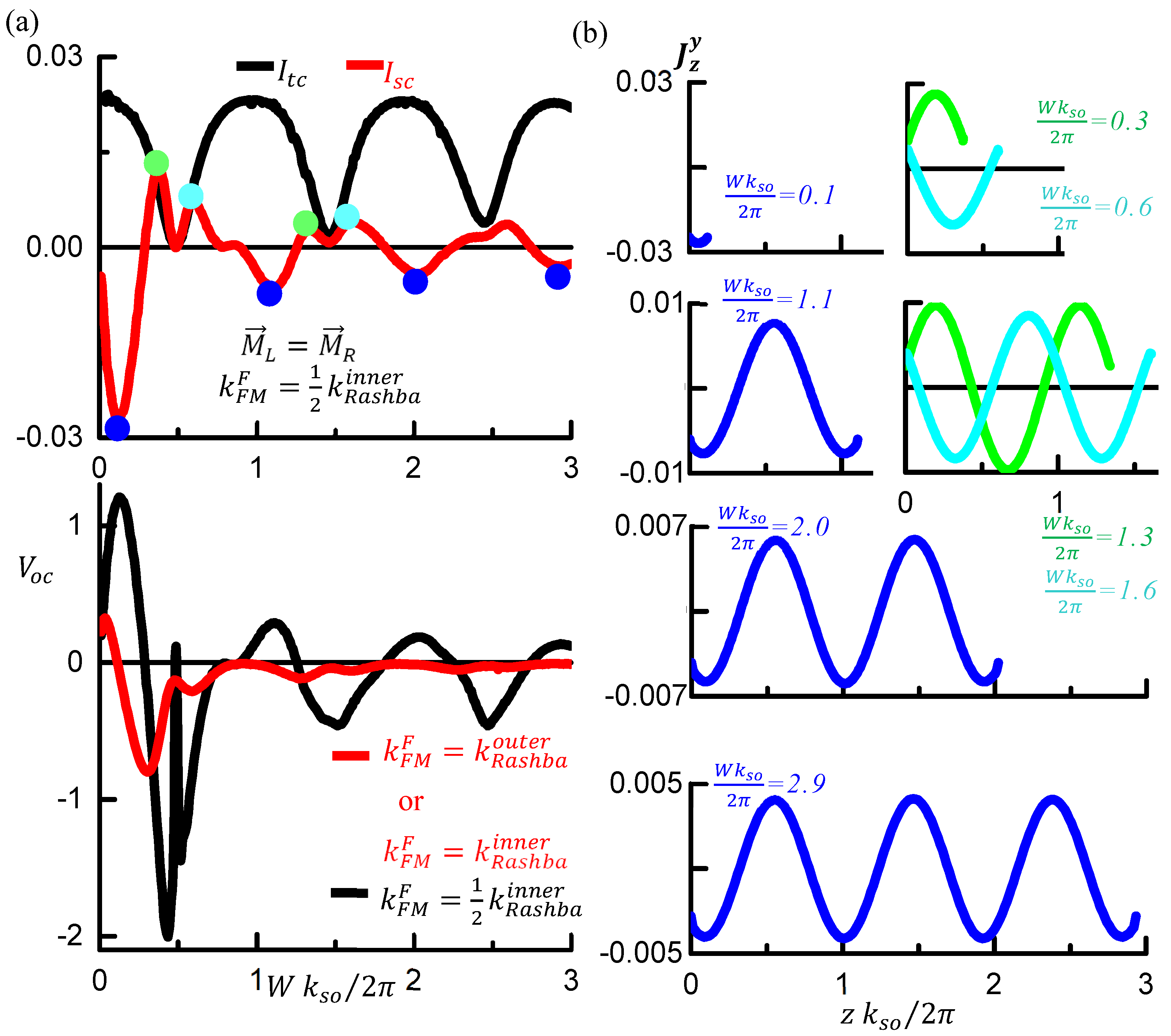
The Fabry-Perot resonance is most pronounced when the magnetization of the ferromagnetic materials is perpendicular to the plane, e.g., along the y-direction. Figure 3 displays the results for M L = M R = y ^ . In addition to the oscillatory features driven by the Fabry-Perot resonance, the signs of I s c and V o c also change with varying channel width. Such a sign change indicates that the spin population in one FM becomes either larger or smaller than in the other. These sign changes are more prominent than those seen in Figure 2b. In the diffusive limit, both I s c and V o c are zero for this magnetization configuration. As shown in Figure 3a, both signals converge to zero as the Rashba region widens. This is attributed to the weakening of phase coherence, which leads to diffusive behavior in a wide Rashba region. Since these signals oscillate around a zero baseline—lacking a DC offset—the sign changes of I s c and V o c are particularly pronounced.
When the resonance is strong, certain electron waves behave as if they are confined within the Rashba channel. In this case, both I t c and I s c approach zero. This confinement leads to a splitting of the original peak in the I s c curve, producing a doublet, as shown in Figure 3a. These doublets are marked by green and cyan dots, and the corresponding spin current profiles are displayed in Figure 3b. The spin current profiles, J z y , are an even function of the transverse position, because m x m z anticommutes with v z σ y .
I s c is the central observable introduced here and is experimentally accessible. In terms of the Hall angle, θ H J z / J x , the normalized I s c scales as θ H k R a s h b a o u t t e r / k R , yielding I s c 0.1 for M L = M R = z ^ (see Figure 2b). For InAs 2DEGs, the ratio k R a s h b a o u t t e r / k R is on the order of 100 [28], which gives θ H ≈ 0.001. The materials with stronger spin–orbit coupling would yield even larger θ H . These magnitudes are well within the range of those that have been experimentally measured in other systems. For instance, the Hall angle of the anomalous Hall effect in various magnetic materials typically ranges from 0.001 to 0.05 [36]. The spin Hall angle in well-characterized semiconductors like n-type GaAs and p-type Si has been measured to be 0.00083 and 0.0001, respectively [37,38]. Therefore, I s c in our Hall system is not merely a theoretical construct but a measurable quantity in standard methods.
The proposed device itself is experimentally realizable. The Hall bar with FM probes can be configured as a Fabry–Perot-type spin interferometer by choosing the channel width comparable to the spin-precession period 2 π / k s o . For a broad class of Rashba materials, this geometric requirement lies comfortably within modern nanofabrication capabilities. For example, the 2 π / k s o of InAs is approximately 1.3 μm [27].
Although our analysis focused on 2D systems, the framework can be readily extended to bulk systems—such as the recently studied ferroelectric material GeTe, which exhibits strong Rashba spin–orbit coupling [39]—by adding a p y 2 / 2 m term to the Hamiltonian and applying appropriate scaling. In this work, spin injection and spin accumulation in the FM are captured by the electrical signals I s c , and V o c , whose origins trace to spin interference and Edelstein spin within the Rashba channel. It is well known that the Edelstein spin contributes to spin torque transfer to the FM [23]. Our Hall geometry has a structure similar to that of spin–orbit torque devices, as an FM is adjacent to a spin–orbit material and an external charge current flows parallel to the interface [1,40]. As shown in Figure 3 of the reference [40], spin–orbit torque devices transfer torque to a magnetic domain primarily via a spin current flowing into the FM, often in the absence of a charge current. This mechanism is analogous to the phenomenon in our system where spin density accumulates in the FM under an open-circuit condition. In our device, this change in the FM’s spin density is expressed as a difference in chemical potential, which is measured as V o c . To demonstrate the fundamental principles in this study, we employed a simplified model: we assumed FMs with 100% polarization and considered only the case where the system reaches a steady state. However, in a real FM with less than 100% polarization, the spin transferred from the Rashba channel could act on the magnetic domain before the spin density reaches a steady state. This dynamic process could lead to magnetization reversal if the coercive force is relatively small. Crucially, this work has demonstrated that the spin transferred to the FM is readily controlled by the spin interference within the Rashba channel. Thus, our results imply that spin interference may also play a significant role in spin torque transfer to the FM, which can be controlled by tuning the Fabry-Pérot resonance.

4. Conclusions

We theoretically investigated a two-dimensional Hall geometry consisting of a Rashba spin–orbit channel coupled to two ferromagnetic (FM) probes. We found that the breaking of mirror symmetry within this structure generates experimentally accessible electrical signals: specifically, an open-circuit voltage ( V o c ) and a short-circuit current ( I s c ). The signals observed in the coherent Rashba channel are driven by two distinct mechanisms: the Edelstein spin density established within the channel and spin interference resulting from multiple reflections at the FM interfaces. A key finding is that the interference in this system is governed solely by the spin-precessional phase, as the contribution from the orbital phase is effectively canceled. By tuning the Rashba channel width, this interference produces Fabry–Pérot-type resonances, which significantly enhance the measured electrical signals. The magnitude of the resulting signals, quantified by the normalized short-circuit current, falls well within the range of previously reported spin Hall angles. This confirms that our proposed device is experimentally realizable using current nanofabrication techniques. Furthermore, since the induced spin current into the FMs can contribute to spin torque transfer, our results suggest that coherent spin interference, in conjunction with the Edelstein effect, offers a controllable pathway for engineering spin torque in hybrid spintronic devices.
In summary, this work highlights the critical role of symmetry breaking and spin interference in Hall geometries and establishes Fabry–Pérot-type resonances as a promising design principle for future spin–orbitronic applications.

Author Contributions

Conceptualization, J.H.; Methodology, S.K.; Software, S.K.; Validation, S.K.; Formal analysis, S.K.; Investigation, S.K.; Data curation, S.K.; Writing—original draft, J.H.; Writing—review and editing, J.H.; Visualization, S.K.; Supervision, S.K.; Project administration, S.K. All authors have read and agreed to the published version of the manuscript.

Funding

This research was supported by the National Research Foundation of Korea (NRF) grant funded by the Korea government (MSIT) (No. RS-2025-00561749).

Data Availability Statement

The original contributions presented in this study are included in the article. Further inquiries can be directed to the corresponding authors.

Conflicts of Interest

The authors declare that there are no competing interest.

References

  1. Han, W.; Otani, Y.; Maekawa, S. Quantum materials for spin and charge conversion. NPJ Quantum Mater. 2018, 3, 27. [Google Scholar] [CrossRef]
  2. Hirohata, A.; Yamada, K.; Nakatani, Y.; Prejbeanu, I.L.; Diény, B.; Pirro, P.; Hillebrands, B. Review on spintronics: Principles and device applications. J. Magn. Magn. Mater. 2020, 509, 166711. [Google Scholar] [CrossRef]
  3. Nguyen, V.D.; Rao, S.; Wostyn, K.; Petit-Watelot, S.; Gaury, B.; Kim, J.; Waintal, X.; Houssameddine, D.; Kent, A.D. Recent progress in spin–orbit torque magnetic random-access memory. npj Spintronics 2024, 2, 48. [Google Scholar] [CrossRef]
  4. Mou, H.; Zhang, Y.; Zhou, L.; Zhu, D.; Liu, Z.; Lu, H.; Han, X.; Guo, Y.; Luo, X. Spin logic devices based on negative differential resistance and beyond. Nano Res. 2024, 31, 1437–1448. [Google Scholar]
  5. Wang, L.; Wesselink, R.J.H.; Liu, Y.; Yuan, Z.; Xia, K.; Kelly, P.J. Giant room temperature interface spin Hall and inverse spin Hall effects. Phys. Rev. Lett. 2016, 116, 196602. [Google Scholar] [CrossRef]
  6. Amin, V.P.; Zemen, J.; Stiles, M.D. Interface-generated spin currents. Phys. Rev. Lett. 2018, 121, 136805. [Google Scholar] [CrossRef]
  7. Liu, L.; Pai, C.; Li, Y.; Tseng, H.W.; Ralph, D.C.; Buhrman, R.A. Spin-torque switching with the giant spin Hall effect of tantalum. Science 2012, 336, 555–558. [Google Scholar] [CrossRef]
  8. Lee, S.; Lee, K. Emerging three-terminal magnetic memory devices. Proc. IEEE 2016, 104, 1831–1843. [Google Scholar] [CrossRef]
  9. Sinova, J.; Valenzuela, S.O.; Wunderlich, J.; Back, C.H.; Jungwirth, T. Spin Hall effects. Rev. Mod. Phys. 2015, 87, 1213–1260. [Google Scholar] [CrossRef]
  10. Edelstein, V.M. Spin polarization of conduction electrons induced by electric current in two-dimensional asymmetric electron systems. Solid State Commun. 1990, 73, 233–235. [Google Scholar] [CrossRef]
  11. Hosokawa, K.; Miwa, S.; Suzuki, Y. Theory of the inverse Rashba–Edelstein effect induced by thermal bias at FI/2DEG interfaces. Phys. Rev. B 2024, 110, 035309. [Google Scholar] [CrossRef]
  12. Hazra, B.; Pal, B.; Jeon, J.; Neumann, R.; Göbel, B.; Grover, B.; Deniz, H.; Styervoyedov, A.; Meyerheim, H.; Mertig, I.; et al. Generation of out-of-plane polarized spin current by spin swapping. Nat. Commun. 2023, 14, 4549. [Google Scholar] [CrossRef] [PubMed]
  13. Park, H.; Ko, H.; Go, G.; Oh, J.; Kim, K.; Lee, K. Spin swapping effect of band structure origin in centrosymmetric ferromagnets. Phys. Rev. Lett. 2022, 129, 037202. [Google Scholar] [CrossRef] [PubMed]
  14. Jung, H.; Park, D.T.; Lee, S.; Kim, U.; Yang, C.; Kim, J.; Umansky, V.; Kim, D.; Sim, H.-S.; Chung, Y.; et al. Observation of electronic modes in open cavity resonator. Nat. Commun. 2023, 14, 415. [Google Scholar] [CrossRef]
  15. Tran, V.; Nguyen, V.; Charlier, J. Klein tunneling degradation and enhanced Fabry–Pérot interference in graphene/h-BN moiré-superlattice devices. 2D Mater. 2024, 11, 025023. [Google Scholar] [CrossRef]
  16. Ihnatsenka, S. Fabry–Pérot and Aharonov–Bohm interference in ideal graphene nanoribbons. Phys. Rev. B 2022, 106, 115408. [Google Scholar] [CrossRef]
  17. Young, A.F.; Kim, P. Quantum interference and Klein tunnelling in graphene heterojunctions. Nat. Phys. 2009, 5, 222–226. [Google Scholar] [CrossRef]
  18. Maciel, R.P.; Araújo, A.L.; Lewenkopf, C.H.; Ferreira, G.J. Fabry-Pérot resonant vortices and magnetoconductance in topological insulator constrictions with magnetic barriers. Phys. Rev. B 2021, 103, 205124. [Google Scholar] [CrossRef]
  19. Alomar, M.I.; Sánchez, D.S. Interplay between resonant tunneling and spin precession oscillations in all-electric, all-semiconductor spin transistors. Phys. Rev. B 2016, 94, 075402. [Google Scholar] [CrossRef]
  20. Qin, H.; Holländer, R.B.; Flajšman, L.; Hermann, F.; Dreyer, R.; Woltersdorf, G.; van Dijken, S. Nanoscale magnonic Fabry–Pérot resonator for low-loss spin-wave manipulation. Nat. Commun. 2021, 12, 2293. [Google Scholar] [CrossRef]
  21. Lutsenko, A.; Fripp, K.G.; Flajšman, L.; Shytov, A.V.; Kruglyak, V.V.; van Dijken, S. Magnonic Fabry–Pérot resonators as programmable phase shifters. Appl. Phys. Lett. 2025, 126, 082406. [Google Scholar] [CrossRef]
  22. Lipson, S.G.; Lipson, H.; Tannhauser, D.S. Optical Physics, 3rd ed.; Cambridge University Press: London, UK, 1995; p. 248. ISBN 0-521-06926-2. [Google Scholar]
  23. Kim, K.; Lee, K.; Sinova, J.; Lee, H.; Stiles, M.D. Spin–orbit torques from interfacial spin–orbit coupling for various interfaces. Phys. Rev. B 2017, 96, 104438. [Google Scholar] [CrossRef]
  24. Kim, K.; Lee, K. Generalized spin drift–diffusion formalism in the presence of spin–orbit interaction of ferromagnets. Phys. Rev. Lett. 2020, 125, 207205. [Google Scholar] [CrossRef]
  25. Inoue, J.; Bauer, G.E.W.; Molenkamp, L.W. Suppression of the persistent spin Hall current by defect scattering. Phys. Rev. B 2004, 70, 041303. [Google Scholar] [CrossRef]
  26. Krotkov, P.L.; Sarma, S.D. Intrinsic spin Hall conductivity in a generalized Rashba model. Phys. Rev. B 2006, 73, 195307. [Google Scholar] [CrossRef]
  27. Jeon, J.; Kim, S.; Kim, T.; Lee, O.; Han, S.; Kim, H.; Koo, H.; Hong, J. Spin transport at a Pt/InAs quantum well interface using spin Hall and Rashba effects. Appl. Phys. Lett. 2020, 117, 042403. [Google Scholar] [CrossRef]
  28. Lee, W.; Kim, S.B.; Kim, K.; Lee, K.; Koo, H.C.; Choi, G. Direct observation of spin accumulation and spin-orbit torque driven by Rashba-Edelstein effect in an InAs quantum-well layer. Phys. Rev. B 2021, 104, 184412. [Google Scholar] [CrossRef]
  29. Alexander, C.; Sadiku, N. Fundamentals of Electric Circuits, 7th ed.; McGraw-Hill: New York, NY, USA, 2021; Chapter 3; pp. 137–143. ISBN 9781260226409. [Google Scholar]
  30. Rodina, A.; Alekseev, A.; Efros, A.; Rosen, M.; Meyer, B. General boundary conditions for the envelope function in the multiband kp model. Phys. Rev. B 2002, 65, 125302. [Google Scholar] [CrossRef]
  31. Sakurai, J.; Napolitano, J. Modern Quantum Mechanics, 2nd ed.; Addison–Wesley: San Francisco, CA, USA, 2011; Chapter 3, Section 3.4. [Google Scholar]
  32. Fabian, A.; Czerner, M.; Heiliger, C. Spin accumulation from nonequilibrium first principles methods. Phys. Rev. B 2021, 104, 054402. [Google Scholar] [CrossRef]
  33. Lundstrom, M. Fundamentals of Carrier Transport, 2nd ed.; Cambridge University Press: Cambridge, UK, 2000; Chapter 3, Section 4; p. 134. [Google Scholar]
  34. Singh, J. Modern Physics for Engineers; John Wiley & Sons: Hoboken, NJ, USA, 2008; Appendix B; p. 353. [Google Scholar]
  35. Datta, S. Electronic Transport in Mesoscopic Systems; Cambridge University Press: Cambridge, UK, 1995; Chapter 2. [Google Scholar]
  36. Yang, J.; Shang, Y.; Liu, X.; Wang, Y.; Dong, X.; Zeng, Q.; Lyu, M.; Zhang, S.; Liu, Y.; Wang, B.; et al. Modulation of the anomalous Hall angle in a magnetic topological semimetal. Nat. Electron. 2025, 8, 386–393. [Google Scholar] [CrossRef]
  37. Garlid, E.S.; Hu, Q.O.; Chan, M.K.; Palmstrøm, C.J.; Crowell, P.A. Electrical measurement of the direct spin Hall effect in FeInxGa1-xAs heterostructures. Phys. Rev. Lett. 2010, 105, 156602. [Google Scholar] [CrossRef] [PubMed]
  38. Ando, K.; Saitoh, E. Observation of the inverse spin Hall effect in silicon. Nat. Phys. 2012, 3, 629. [Google Scholar] [CrossRef] [PubMed]
  39. Jeon, J.; Cho, S.; Lee, O.; Hong, J.; Kwak, J.Y.; Han, S.; Jung, S.; Kim, Y.; Ko, H.; Lee, S.; et al. Field-like spin–or-bit torque induced by bulk Rashba channels in GeTe/NiFe bilayers. NPG Asia Mater. 2021, 13, 76. [Google Scholar] [CrossRef]
  40. Sahoo, R.C.; Duong, D.L.; Yoon, J.; Hai, P.N.; Lee, Y.H. Spin-orbit torque: Moving towards two-dimensional van der Waals heterostructures. arXiv 2018, arXiv:2108.10622v1. [Google Scholar] [CrossRef]
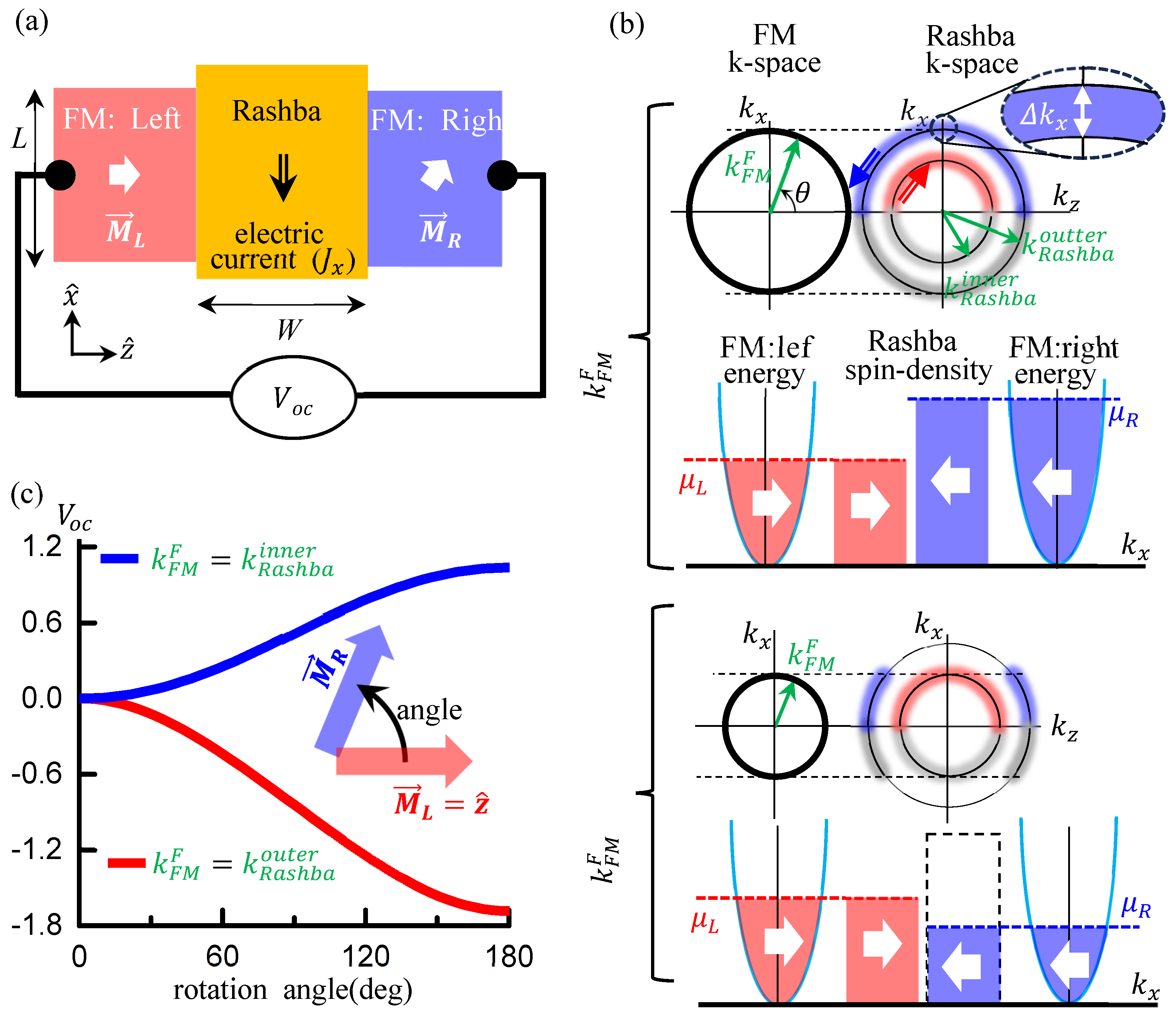
Figure 1. Schematic of the system and the diffusive Rashba channel (a) Hall geometry consisting of a Rashba channel and ferromagnetic (FM) electrodes. L ( W ) is longitudinal (transverse) size of the FM probe, and M L ( M R ) is magnetization direciton of the left (right) FM probe. An externally applied bias drives a charge current J x along the x direction in the Rashba channel, while the transverse voltage V o c along the z-direction is measured by the FM probes. (b) Illustration of V o c generation in the diffusive Rashba channel with magnetization configuration M L = M R = z ^ . The blue (red) arrow represents spin direction of the outer (inner) Fermi surface, and k R a s h b a o u t e r ( k R a s h b a i n n e r ) is a radius of the outer (inner) Fermi surface in k-space. μ L ( μ R ) is a chemical potential of the left (right) FM probe. The first panel shows the Fermi surface for k F M F =   k R a s h b a o u t e r , and the second panel depicts the spin density in the Rashba channel together with the chemical potential of the FM probes. The corresponding diagrams for k F M F = k R a s h b a i n n e r are shown in the third and fourth panels. The outer Fermi surface (blue blurry curves in the first and third panels) yields a negative z-component of spin density, while the inner Fermi surface (red blurry curves) produces a positive one. (c) V o c as a function of the rotation angle of the right FM magnetization. M L is fixed along z ^ , while M R is rotated about the y-axis. V o c < 0 for k F M F =   k R a s h b a o u t e r , whereas V o c > 0 for k F M F =   k R a s h b a i n n e r . At M R = z ^ the Hamiltonian has m z symmetry and V o c vanishes, while for M R = z ^ the Hamiltonian has m x m z symmetry and V o c is maximum. The value of V o c was divided by k s o J x 2 e 2 n to make it dimensionless, where n is carrier density in the Rashba channel.
Symmetry 17 01991 g001
Figure 2. Fabry-Perot resonance in the coherent Rashba channel. (a) Schematic of an equivalent circuit of our system. Electrons in the Rashba channel undergo multiple reflections at both interfaces, leading to spin interference. Black arrows schematically represent the trajectories of electrons undergoing these multiple reflections. (b) Upper panel: short-circuit current I s c and transverse-circuit current I t c as functions of the Rashba channel width W . Lower panel: V o c for two k F M F as a function of W . Both I s c   and I t c exhibit oscillations with a characteristic period set by the spin-precession length, 2 π / k s o , originating from spin interference due to interface reflections. The amplitudes of these signals are maximized at Fabry–Perot resonances. V o c is obtained from I s c and I t c (see Equation (5) in the main text). (c) Profiles of the spin current J z z along the transverse (z) direction under the short-circuit condition. The results are shown for channel widths corresponding to the maxima of I s c , indicated by blue dots in (b). The values of I t c , I s c , V o c and J z z were normalized by dividing them by π 2 e 2 n , k s o J x 2 π n , k s o J x 2 e 2 n and 1 8 π k s o J x e n , respectively, to be dimensionless.
Symmetry 17 01991 g002
Figure 3. FM probes with out-of-plane magnetization. Both left and right FM probes are magnetized along the +y−direction, and transport in the Rashba channel is coherent. (a) I s c , I t c and V o c as functions of the Rashba channel width for k F M F = 1 2 k R a s h b a i n n e r . (b) Spin current profiles under the short-circuit condition for k F M F =   k R a s h b a i n n e r / 2 . The left column shows the profiles for channel widths corresponding to the minima of I s c , indicated by blue dots in (a). The right column shows the profiles for widths corresponding to the maxima of I s c , marked by green and cyan dots in (a). I t c , I s c and V o c were normalized as described in the caption of Figure 2, and J z y was normalized in the same manner as J z z .
Symmetry 17 01991 g003
Disclaimer/Publisher’s Note: The statements, opinions and data contained in all publications are solely those of the individual author(s) and contributor(s) and not of MDPI and/or the editor(s). MDPI and/or the editor(s) disclaim responsibility for any injury to people or property resulting from any ideas, methods, instructions or products referred to in the content.