Article

Leveraging the Symmetry Between Active Dual-Steering-Wheel MPC and Passive Air Bearing for Ground-Based Satellite Hovering Tests

1
State Key Laboratory of Robotics and Systems, Harbin Institute of Technology, Harbin 150001, China
2
Shenyang Institute of Automation, Chinese Academy of Sciences, Shenyang 110016, China
3
Aerospace System Engineering Shanghai, Shanghai 201109, China
4
Song Jiang Laboratory, Harbin Institute of Technology, Harbin 150001, China
5
University of Chinese Academy of Sciences, Beijing 100049, China
*
Authors to whom correspondence should be addressed.
Symmetry 2025, 17(11), 1990; https://doi.org/10.3390/sym17111990
Submission received: 9 October 2025 / Revised: 8 November 2025 / Accepted: 10 November 2025 / Published: 17 November 2025
(This article belongs to the Section Engineering and Materials)

Abstract

Satellite hovering missions involve an active propulsion phase for precise maneuvering and a subsequent passive dynamics phase wherein the satellite responds to external forces, such as from a manipulator. Therefore, a ground-testing method capable of seamlessly integrating these operational regimes is required. This paper presents a novel methodology that leverages the symmetry between active wheel-driven control and passive air-bearing dynamics to establish a unified testing platform. A mathematical model is established for the dual independent steering-wheel drive system, and an error model for tracking both the translational (position) trajectory and the rotational (attitude) trajectory of the satellite during hovering is derived. Based on this, a Model Predictive Control (MPC) scheme is designed to generate optimal driving speeds and steering angles for the wheels, ensuring accurate trajectory tracking while explicitly adhering to their driving and steering constraints. Furthermore, our work involves the integrated design of a gravity-compensated platform and its steering wheels, incorporating design methods to enhance air-bearing safety and a seamless switching method to maintain test continuity by minimizing transient disturbances. Experiments demonstrate that this integrated platform delivers both high-precision satellite trajectory tracking and high-fidelity passive air-bearing micro-gravity simulation for the active and passive phases of a satellite hovering mission.

1. Introduction

1.1. Ground Testing Needs for Satellite Hovering Missions

Spacecraft hovering, which enables prolonged close-range observation, inspection, and interaction with asteroids, space debris, or other spacecraft [1], has become a vital capability for advanced space missions [2]. The highly dynamic deep-space environment, inherent dynamical model inaccuracies, and significant ground communication delays pose substantial challenges for satellite hovering and proximity operations [3]. The effectiveness and adaptability of any proposed hovering control method must ultimately be validated through high-fidelity ground testing.
The complexities of satellite hovering impose stringent requirements on such tests. Missions must coordinate the observational relationships between multiple spacecraft and effectively handle mutual occlusion caused by target morphology changes or limited sensor fields of view, as these factors directly impact navigation accuracy and control stability [4]. Furthermore, during proximity maneuvers, the spacecraft must simultaneously satisfy multiple constraints—such as collision avoidance and specific attitude pointing—placing high demands on the computational efficiency of real-time trajectory generation [5]. Failure to meet these demands can result in mission failure or equipment damage [6]. These challenges necessitate ground-testing equipment capable of precisely simulating the satellite’s hovering navigation trajectory to validate control algorithms and mitigation strategies for issues like occlusion.
From a control perspective, the complexity of inter-satellite dynamics increases significantly when the target is tumbling or non-cooperative [7], with controllability and stability notably degrading in underactuated conditions [8]. Research into these dynamics underscores the need for ground tests to accurately simulate the satellite’s mass and inertia properties. In summary, ground-based testing for satellite hovering has two critical components: the simulation of the hovering orbital trajectory and the simulation of the satellite’s control dynamics. While previous studies have leveraged ground hardware-in-the-loop experiments to investigate navigation and control accuracy [9] or used air-bearing platforms to emulate parameters like the moment of inertia [10], a methodology that integrates both high-fidelity trajectory tracking and full physical dynamics simulation on a single platform remains under-explored. Establishing such a comprehensive ground simulation environment is now an indispensable step in enhancing mission reliability and reducing on-orbit risks.
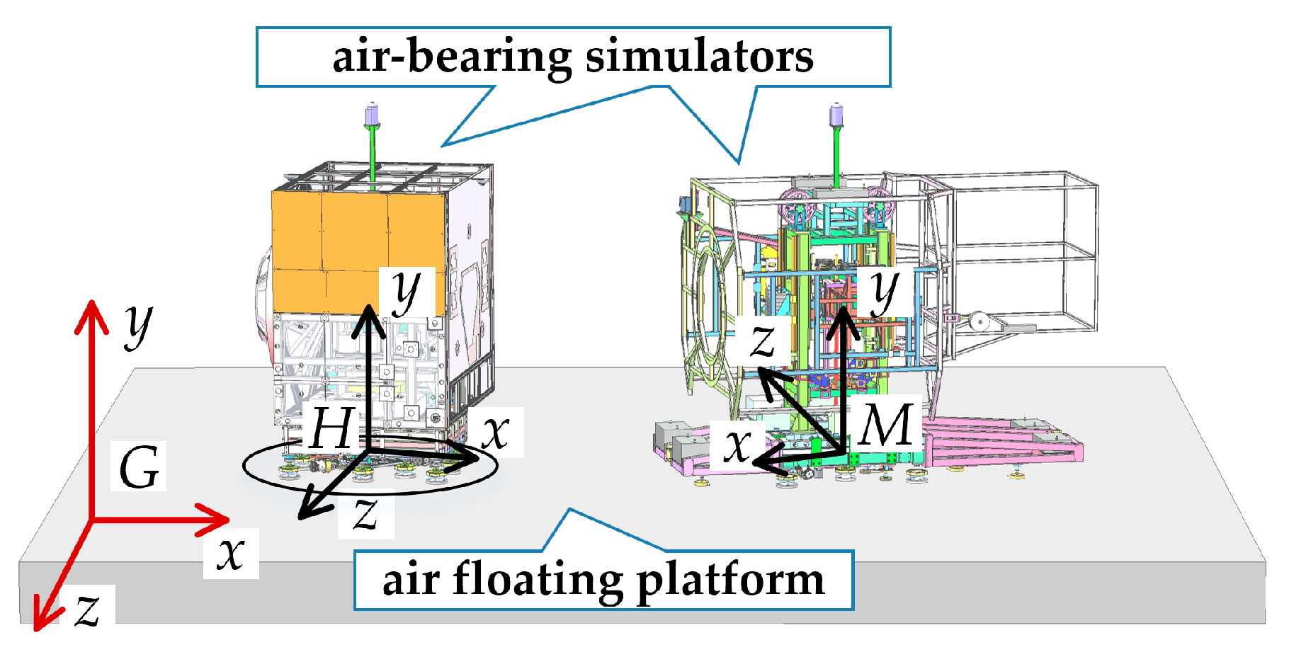
The core objective of this work is to develop an integrated micro-gravity simulation platform for satellite hovering tests, which unifies active trajectory motion and passive motion simulation. Figure 1 provides a schematic diagram that delineates the specific experiments conducted for the ground-based satellite hovering tests in this study and contrasts the proposed methodology with conventional approaches. For the active control strategy, all steering wheels feature independent steering—a departure from conventional designs. Correspondingly, we develop a mathematical model and an MPC-based tracking framework with integrated attitude control. The introduction that follows reviews literature related to MPC and air bearing technologies for ground-based testing.

1.2. The Active Element: MPC for Trajectory and Attitude Tracking

To address the need for precise trajectory simulation, this paper employs two independently controlled steering wheels as actuators. The requirement extends beyond conventional two-dimensional path tracking to include the control of the satellite simulator’s attitude, constituting a more complex pose tracking problem. For this active control task, we adopt Model Predictive Control (MPC), a methodology widely recognized in academia and industry for its performance in constrained multivariable systems [11]. This predictive control strategy is uniquely suited to our application, as it enables smooth, anticipatory trajectory and attitude tracking while rigorously adhering to the critical steering and driving constraints of the dual-wheel system.

1.2.1. The Extensive Applications of MPC

The versatility and effectiveness of Model Predictive Control (MPC) have been extensively validated across numerous engineering disciplines. In vehicle dynamics, its applications span from additional yaw moment compensation [12] and parallel parking [13] to vehicle lateral stability control [14]. The framework demonstrates remarkable adaptability, as evidenced by the development of robust variants integrating neural networks [15], hybrid adaptive Nonlinear MPC (NMPC) schemes [16], and successful implementations in underactuated systems [17,18].
Beyond automotive applications, MPC exhibits outstanding performance in diverse domains. It achieves high-fidelity simulation testing [19] and precise attitude control during spacecraft orbital rendezvous [20]. For complex dynamics and actuation redundancy in dual-axis tilting quadrotors, researchers have employed an NMPC framework to achieve exceptional control performance [21]. Its applications further extend to industrial equipment, where multi-dimensional controllable power sources and their bi-level optimization architecture fundamentally address energy consumption issues in hybrid equipment, representing a groundbreaking advancement for low-carbon design [22]. Additional implementations include power electronics, where Finite Control Set MPC enhances FPGA resource utilization [23]; building energy management, where it optimizes indoor temperature control [24]; and process industries, where it serves as a key technology for managing large-scale interconnected systems [25].

1.2.2. Theoretical Development in MPC

The theoretical foundation of MPC continues to be strengthened through ongoing algorithmic innovations. Research has introduced neural networks to alleviate the computational burden of traditional MPC, significantly improving online computational efficiency [26]. The integration of active learning and deep learning for model refinement [27], combined with synergistic collaboration with reinforcement learning, opens new avenues for learning-based control [28]. Regarding MPC stability, studies on stable estimation and control of nonlinear systems under disturbances provide theoretical insights for stability analysis [29]. By incorporating terminal conditions, researchers ensure monotonic decrease in the cost function, thereby providing proofs for asymptotic stability in MPC schemes [30,31] and guaranteeing closed-loop asymptotic stability.

1.2.3. The Superior Performance of MPC in Trajectory Tracking

For the specific task of trajectory tracking, MPC demonstrates distinct advantages in enhancing tracking accuracy [32]. It has been successfully deployed in UAV moving target tracking [33] and autonomous vehicle path tracking [34]. Its capabilities often extend beyond pure tracking to include higher-level functionalities such as situational awareness in autonomous driving [35] and fault compensation in quadrotor systems [36].

1.2.4. Implementation of MPC in This Work

The requirements of our ground-based test—multi-degree-of-freedom active trajectory and attitude tracking under the actuation constraints of the steering wheels—directly align with the core competencies of MPC. Independent steering control for each wheel is essential to generate the specific forces and moments required for integrated pose tracking. This configuration differs from conventional wheeled platforms used in trajectory tracking studies. To implement MPC for our specific system, we therefore derive the vehicle kinematics model and construct the predictive control framework accordingly.

1.3. The Passive Element: Air-Bearing for Micro-Gravity Simulation

The passive element of our symmetrical design is dedicated to creating a high-fidelity micro-gravity environment. This is particularly vital during mission phases involving physical interactions, such as when a robotic arm captures a target, and the accurate replication of the satellite’s mass and inertia properties becomes paramount for credible ground-testing outcomes. High-fidelity physical air-bearing satellite simulators represent a cornerstone technology for this purpose, providing a critical experimental platform for spacecraft dynamics validation [37]. By suspending the test simulator on a thin film of pressurized air, these systems effectively eliminate nearly all friction, enabling the ultra-low friction motion necessary to accurately emulate the dynamics of orbital flight [38]. The high fidelity of this simulation method has been consistently demonstrated through its application in a wide array of complex mission scenarios, including the validation of on-orbit control strategies for satellite soft docking and close-proximity hovering maneuvers [39].

1.3.1. Applications of Air-Bearing Motion

The utility of air-bearing technology extends across various testing needs. Spherical air-bearing testbeds, for instance, offer a unique capability for validating complex attitude determination and control algorithms for small satellites [40]. Furthermore, the versatility of these platforms is highlighted by their use in advanced research, such as the study of collision-free path planning and tracking control for multi-agent systems in complex three-dimensional space, as investigated by Rong Chen et al. [41]. The fundamental strength of air-bearing technology lies in facilitating high-precision, multi-degree-of-freedom motion by negating the effects of friction, a feature that has driven its applied progress in numerous domains [42]. In the realm of high-precision actuation, air-bearings are unparalleled. By completely eliminating friction loss and mechanical contact forces, they form the basis for systems that demand exceptional output accuracy and motion smoothness [43,44]. This inherent performance makes air-bearing motion platforms an ideal testbed for verifying advanced control algorithms [45]. They have been successfully employed in studies on the cooperative control of multi-spacecraft systems [46], the development of novel spacecraft control methods [47], the ground verification of systems accounting for time-delay [48], and as the core of spacecraft simulators utilizing reaction wheels and jet systems as primary actuators [49].While the primary function of an air-bearing is to enable passive motion simulation—faithfully reflecting the Newtonian dynamics of a free-flying body—scholars have integrated active actuation mechanisms to expand their functionality. For example, Menghao Zhao et al. introduced a satellite simulator that directly uses cold-gas jet thrusters for active attitude control [50]. Other approaches have explored the use of reaction wheels or analogous devices, such as the rotating-mass-driven simulator studied by Roshan A. Chavan et al. [51] and the reaction wheel-based active motion control investigated by Somayeh Jamshidi et al. [52].

1.3.2. Active Actuation Strategy in This Work

In our testing platform, the air-bearing is utilized to realize the passive element of the satellite hovering simulation. For the active element, two steering wheels are employed atop the air-bearing platform to provide the active driving force for the satellite simulator, thereby replicating the satellite’s navigational trajectory. A key feature of this design is that the wheel-driven actuation can be engaged and disengaged at will from the air-bearing system. This capability to dynamically switch between driven and free-floating states enables us to realize a symmetrical ground-testing platform for satellite hovering, seamlessly integrating both active and passive operational phases.

1.4. Contributions and Organization

This paper presents a holistic ground-testing methodology that leverages a symmetrical design integrating an active dual-steering-wheel drive and a passive air-bearing platform. This unified approach enables complete testing of both the active navigation and passive micro-gravity dynamics phases of a satellite hovering mission on a single apparatus, with rapid switching between operational states. For active motion, Model Predictive Control (MPC) is utilized to drive the satellite simulator using two steering wheels with actuation limits, achieving simulation of satellite hovering trajectories. Regarding active-passive switching, a quantitative analysis of the steering wheel contact force design is provided, which fulfills the experimental motion requirements while ensuring stable system switching between active and passive modes, thereby establishing the constraints required for the MPC solution. For passive motion, air-bearing technology is employed to simulate the weightlessness environment, and a full-physics testing method is used to replicate the satellite’s mass and inertia characteristics. During the experimental phase, tests were conducted on both active and passive motion components, with data indicating stable system operation.
The contributions of this paper are reflected in the following four innovative aspects:
Innovation 1: Innovatively combines steering wheel drive with air-bearing gravity compensation, introducing wheeled drive methods into spacecraft ground simulation testing. Proposes a wheeled driving approach under air-bearing gravity compensation conditions and realizes switching between active driving and passive air-bearing motion.
Innovation 2: Extends the traditional wheeled vehicle model to a form where each wheel can steer independently, provides the driving model for the wheeled mechanism under conditions of all-wheel independent steering, and establishes the constraints for multi-wheel independent steering control.
Innovation 3: Based on the independent steering wheel model, presents an MPC method for active tracking of satellite hovering trajectories by the air-bearing gravity compensation simulator driven by steering wheels.
Innovation 4: Provides constraints that satisfy both the simulator’s active motion control requirements and the requirements for stable active-passive switching. Integrates these constraints with the MPC solution constraints to design a receding horizon optimal controller, thereby optimizing the performance of the closed-loop system.
The subsequent sections of this paper are organized as follows: Section 2 establishes the attitude-included satellite hovering trajectory tracking error model and presents the trajectory tracking control method. Section 3 details the active-passive symmetric design method, describes the microgravity simulation method for the full-physics satellite simulator, and integrates switching conditions with MPC solution constraints. Section 4 sets up the experimental platform and provides the test results for both active and passive motion. Section 5 discusses and summarizes the work of this paper and offers an outlook for future research.

2. Modeling of Dual-Steering-Wheel Drive and MPC for Hovering Trajectory Tracking

This chapter presents a method for employing a wheeled mechanism to simulate active trajectory motion in satellite hovering ground tests, under conditions of air-floating gravity compensation. As shown in Figure 2, two air-bearing simulators are set up on the platform to emulate a pair of satellites in relative hovering. A global coordinate frame, denoted as the G-frame, is defined. The two satellite simulators are rigidly attached to the H-frame and the M-frame, respectively, with their orientations illustrated in the figure. Consequently, the motion of each simulator can be described by the motion of its respective frame (H or M) relative to the global G-frame. For simplicity, we will hereafter refer to the two simulators as the H-simulator and the M-simulator. The XZ plane coincides with the air-bearing plane. Driven by the steering wheels, both simulators can move within the XZ plane of the global frame, exhibiting motion along the X-axis, motion along the Z-axis, and rotation about the Y-axis—thus possessing three degrees of freedom.

2.1. Modeling of the Dual-Steering-Wheel Drive System

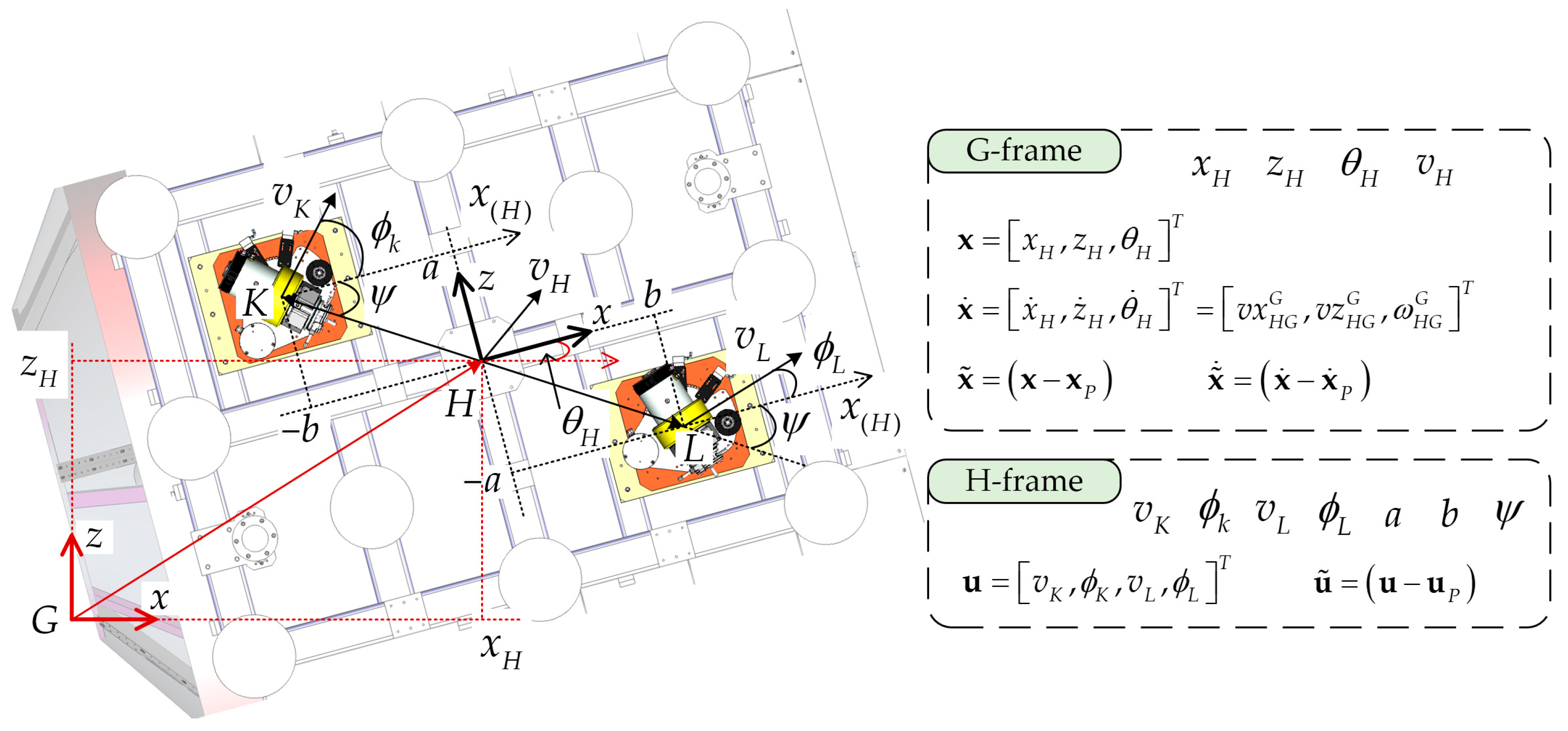
Given that the kinematic description and control methodology are identical for both simulators; the following discussion will detail the motion of the H-frame relative to the G-frame as a representative example. Isolating the chassis of the H-simulator (highlighted by a circle in Figure 2) and viewing it from below yields the structural diagram shown in Figure 3. This setup comprises two steering wheels, designated as the K-wheel and the L-wheel. The steering angle φ and the driving speed v of each wheel relative to the H-simulator can be controlled independently. The steering angle is defined as 0° when the wheel’s driving direction aligns with the positive X-axis of the H-frame, with the positive rotation direction defined by the right-hand rule about the H-frame’s y-axis. The positions of both wheels relative to the H-simulator body are fixed and are symmetrically arranged about the origin of the H-frame.
Since the H-frame moves solely within the XZ plane of the G-frame, its pose (position and orientation) relative to the G-frame can be described by the x-coordinate x H of point H, the z-coordinate z H of point H, and the rotation angle θ H about the y-axis. Therefore, the system state vector is defined as:
x = x H , z H , θ H T
The derivative of the system state vector is given by:
x ˙ = x ˙ H , z ˙ H , θ ˙ H T = v x H G G , v z H G G , ω H G G T
The subscripts for velocity variables are defined as follows: v x H G G denotes the velocity component along the x-direction. The subscript HG indicates that this is the velocity of point H relative to the G-frame, while the superscript G specifies that the x-direction is defined by the G-frame, meaning the velocity is expressed in the G-frame. Thus, each velocity variable is defined by three pieces of auxiliary information: the two entities in relative motion and the coordinate frame in which the quantity is expressed. These detailed subscripts are introduced to facilitate subsequent discussion. The notation for vectors in the following text follows a similar convention.
The relationship between the driving steering wheels and the system state can be derived using the theory of coordinate transformation for vector velocities in three-dimensional moving frames. First, we define the representation of some key vectors: r H K G is the vector from point H to point K, expressed in the G-frame. Ω H G G is the skew-symmetric matrix form of the angular velocity of the H-frame relative to the G-frame, expressed in the G-frame. The matrix Ω H G G and the vector ω H G G (the angular velocity vector) are defined by the following relationship:
Ω H G G = 0 ω z H G G ω y H G G ω z H G G 0 ω x H G G ω y H G G ω x H G G 0
The G-frame is the inertial frame, and the H-frame is the moving frame. For points K and L, which are stationary within the H-frame, their velocities relative to the inertial G-frame, denoted as v K G G and v L G G , respectively, are related to the translational velocity v H G G and the rotational velocity ω H G G of the moving frame (i.e., the H-simulator) relative to the inertial frame by the following kinematic relations:
v K G G = v H G G + Ω H G G r H K G v L G G = v H G G + Ω H G G r H L G
This relationship can also be obtained by differentiating the following vector equation on both sides:
G K G = G H G + H K G = G H G + R G H H K H G L G = G H G + H L G = G H G + R G H H L H
v K G G = v H G G + Ω H G G R G H r H K H + R G H r ˙ H K H v L G G = v H G G + Ω H G G R G H r H L H + R G H r ˙ H L H
Since r H K H and r H L H are constant vectors, Equation (6) simplifies to Equation (4).
At this point, we have established the relationship, expressed in the global G-frame, between the motion of the steering wheels and the derivative of the system state. However, this formulation is not convenient for practical use. This is because the positions of the two wheels are fixed relative to the H-simulator frame, and their steering angles are defined with respect to the H-frame. Therefore, it is preferable to describe the wheel kinematics within the H-frame itself. According to the transformation law for angular velocity vectors,
Ω H G G = R G H Ω H G H R H G
we obtain:
v K G G = v H G G + R G H Ω H G H R H G r H K G v L G G = v H G G + R G L Ω H G H R H L r H L G
left-multiplying both sides by R H G
R H G v K G G = R H G v H G G + R H G R G H Ω H G H R H G r H K G R H G v L G G = R H G v H G G + R H G R G H Ω H G H R H G r H L G
By expressing the steering wheel kinematics in the H-frame, we have now derived the relationship between the variables in the most convenient coordinate frame for our control design.
v K G H = R H G v H G G + Ω H G H r H K H v L G H = R H G v H G G + Ω H G H r H L H
The positions of the two wheels in the H-frame are defined as:
r H K H = b , 0 , a T
r H L H = b , 0 , a T
where a and b are constant positional parameters. The angular velocity of the H-frame relative to the global frame is given by:
ω H G G = 0 , θ ˙ H , 0 T
Consequently, the rotation matrix from the global frame (G) to the H-frame is given by:
R H G = R G H T = cos θ H 0 sin θ H 0 1 0 sin θ H 0 cos θ H
Since
ω H G H = R H G ω H G G = ω H G G
Therefore, the expression of the H-frame’s angular velocity relative to the global frame is equivalent in both the H-frame and the G-frame. Consequently, the skew-symmetric matrix of the angular velocity is also identical in both coordinate frames and holds the following relationship with the θ ˙ H component of the system state derivative:
Ω H G G = Ω H G H = 0 0 θ ˙ H 0 0 0 θ ˙ H 0 0
The velocity v H G G of the H-simulator relative to the global G-frame is related to the x ˙ H and z ˙ H components of the system state derivative as follows:
v H G G = x ˙ H , 0 , z ˙ H T
Defining the driving speed of the K-wheel as v K and its steering angle as ϕ K , the driving velocities of both steering wheels expressed in the H-frame satisfy the following relation:
v K H H = v K cos ϕ K , 0 , v K sin ϕ K T v L H H = v L cos ϕ K , 0 , v L sin ϕ K T
Assuming no sliding friction exists between the K-wheel/L-wheel and the ground relative to the global frame during driving, the following kinematic constraint holds:
v K H H = v K G H v L H H = v L G H
Substituting Equations (11), (12), (14), (16), (18) and (19) into Equation (10) yields the differential equation of the system state.
v K cos ϕ K = x ˙ H cos θ H z ˙ H sin θ H θ ˙ H a v K sin ϕ K = x ˙ H sin θ H + z ˙ H cos θ H + θ ˙ H b v L cos ϕ L = x ˙ H cos θ H z ˙ H sin θ H + θ ˙ H a v L sin ϕ L = x ˙ H sin θ H + z ˙ H cos θ H θ ˙ H b
Solving this nonlinear state equation yields the solution for the derivative of the system state as:
x ˙ H = 1 2 v K cos θ H + ϕ K + 1 2 v L cos θ H + ϕ L z ˙ H = 1 2 v K sin θ H + ϕ K 1 2 v L sin θ H + ϕ L θ ˙ H = 1 2 a v L cos ϕ L v K cos ϕ K
At this point, θ ˙ H admits an alternative solution expressed by the following equation:
θ ˙ H = 1 2 b v L sin ϕ L v K sin ϕ K
Therefore, the steering wheel actuation, which constitutes the system input, must satisfy the following constraint:
a v L sin ϕ L v K sin ϕ K b v L cos ϕ L v K cos ϕ K = 0
It is important to note that the two independently controlled steering wheels, with their steering angles and driving speeds, provide four control inputs to the system, whereas the system itself possesses only three states. Consequently, the four inputs must satisfy a specific constraint condition to effectively reduce the number of independent inputs to three. This redundancy can be understood physically by defining an auxiliary angle ψ that satisfies:
sin ψ = a a 2 + b 2
cos ψ = b a 2 + b 2
Then we have:
v K cos ψ cos ϕ K sin ψ sin ϕ K = v L cos ψ cos ϕ L sin ψ sin ϕ L
v K cos ψ + ϕ K = v L cos ψ + ϕ L
From Equation (27), it can be observed that the driving velocity components of the two steering wheels along the line connecting them must be equal, which aligns with an intuitive physical understanding of the system’s kinematics.
Defining the system’s inputs and outputs:
x = x H , z H , θ H T
x ˙ = x ˙ H , z ˙ H , θ ˙ H T
u = v K , ϕ K , v L , ϕ L T
Thus, the system’s state-space equation can be written as Equation (31).
x ˙ = f x , u
Equation (21) presents the expanded form of Equation (31). At this stage, we have successfully derived the nonlinear time-varying state-space equation of the system and have thoroughly discussed the constraint conditions that exist among the system inputs.

2.2. Formulation of the Pose Tracking Error Model

The subsequent discussion focuses on how the system model can be used to track a predefined state trajectory x P t . This trajectory represents the satellite hovering path to be simulated on the ground. The corresponding system input trajectory u P t , is also known. By linearizing the system around this reference trajectory at any given time t , we obtain:
x ˙ = x ˙ P + f x , u x x x P + f x , u u u u P
Taking the partial derivative of Equation (31) with respect to the system state yields:
f x , u x = 0 0 1 2 v K sin ( θ + ϕ K ) 1 2 v L sin ( θ + ϕ L ) 0 0 1 2 v K cos ( θ + ϕ K ) 1 2 v L cos ( θ + ϕ L ) 0 0 0
Taking the partial derivative of Equation (31) with respect to the system input yields:
f x , u u = 1 2 cos θ + ϕ K 1 2 v K sin θ + ϕ K 1 2 cos θ + ϕ L 1 2 v L sin θ + ϕ L 1 2 sin θ + ϕ K 1 2 v K cos θ + ϕ K 1 2 sin θ + ϕ L 1 2 v L cos θ + ϕ L 1 2 a cos ϕ K v K 2 a sin ϕ K 1 2 a cos ϕ L v L 2 a sin ϕ L
Defining the error state as x ˜ and the error input as u ˜ ,
x ˜ = x x P
u ˜ = u u P
x ˜ ˙ = x ˙ x ˙ P
The resulting error state equation is given by:
x ˜ ˙ t = f x , u x x ˜ t + f x , u u u ˜ t
We perform spatial linearization to obtain the continuous state-space expression above. On this basis, we use Taylor expansion for time discretization to derive the discrete equation,
x ˜ t k + Δ t = x ˜ t k + x ˜ ˙ t k Δ t + 1 2 x ˜ ¨ t k Δ t 2 +
Under the condition of a small discretization period, we omit the higher-order terms,
x ˜ t k + Δ t = x ˜ t k + x ˜ ˙ t k Δ t
Substituting the definitions and the continuous model:
x ˜ t k + Δ t = x ˜ k + 1 ,   x ˜ t k = x ˜ k ,   u ˜ t k = u ˜ k
x ˜ ˙ t k = f x , u x x ˜ k + f x , u u u ˜ k
We arrive at the discrete equation at time step k as follows:
x ˜ k + 1 = I + Δ t f x , u x x ˜ k + Δ t f x , u u u ˜ k
Defining matrices A and B as the coefficients of the discretized error state equation,
A = I + Δ t f x , u x
B = Δ t f x , u u
Introducing the time step subscript k for the vectors yields the discretized error equation of the system as follows:
x ˜ k + 1 = A x ˜ k + B u ˜ k
The discretized error equation describes the state and input errors of the system when tracking the reference trajectory, and it forms the foundation for designing the MPC controller in the subsequent sections.

2.3. MPC Design for Satellite Hovering Trajectory Tracking

Applying MPC requires predicting the system behavior over a future horizon of n time steps from the current moment k and solving for the optimal sequence of inputs over this horizon. Since the coefficient matrices A and B in the error model are state-dependent, linearization is performed at each sampling instant based on the current state. To ensure the accuracy of this linearized approximation throughout the prediction range, the prediction horizon is set to a short number of steps (the specific value is provided in Section 4.2). The experimental results in Section 4.2 verify the effectiveness of this approach. To formulate a linearly solvable optimal control problem, a new augmented system state λ k is defined as follows:
λ k = x ˜ k T , u ˜ k 1 T T 7 * 1
the state λ k + 1 at the next time step can be expressed as:
λ k + 1 = x ˜ k + 1 u ˜ k = A x ˜ k + B u ˜ k u ˜ k
λ k + 1 = A x ˜ k + B u ˜ k 1 + B u ˜ k B u ˜ k 1 u ˜ k 1 + u ˜ k u ˜ k 1
λ k + 1 = A x ˜ k + B u ˜ k 1 u ˜ k 1 + B u ˜ k B u ˜ k 1 u ˜ k u ˜ k 1
λ k + 1 = A B 0 4 * 3 I 4 * 4 λ k + B I 4 * 4 u ˜ k u ˜ k 1
Defining the new system matrix as A ˜ , the new input matrix as B ˜ , and the new output matrix as C ˜ ,
A ˜ = A B 0 I 7 * 7
B ˜ = B I 7 * 4
C ˜ = I 3 * 3 , 0 3 * 4 3 * 7
defining the new system input as Δ u ˜ k :
Δ u ˜ k = u ˜ k u ˜ k 1
defining the new system output as λ k , where this output physically represents the state and input deviations of the simulator from the known reference trajectory. This yields the new state-space equation and output equation as follows:
λ k + 1 = A ˜ λ k + B ˜ Δ u ˜ k
y k = C ˜ λ k
Based on the new state equation derived above, the output equations for the next n future periods are now derived and expressed in a linear matrix form.
y k + 1 = C ˜ A ˜ λ k + C ˜ B ˜ Δ u ˜ k
y k + 2 = C ˜ A ˜ 2 λ k + C ˜ A ˜ B ˜ Δ u ˜ k + C ˜ B ˜ Δ u ˜ k + 1
y k + n = C ˜ A ˜ n λ k + C ˜ A ˜ n 1 B ˜ Δ u ˜ k + C ˜ A ˜ n 2 B ˜ Δ u ˜ k + 1 + + C ˜ A ˜ 0 B ˜ Δ u ˜ k + n 1
Once again, we define new aggregated vectors for the future outputs and inputs over the next n periods:
y k = y k + 1 y k + 2 y k + n 3 n * 1
Δ u k = Δ u ˜ k Δ u ˜ k + 1 Δ u ˜ k + n 1 4 n * 1
and the coefficient matrices V and W are defined as:
V = C ˜ A ˜ C ˜ A ˜ 2 C ˜ A ˜ n 3 n * 7
W = C ˜ B ˜ 0 3 * 4 0 3 * 4 C ˜ A ˜ B ˜ 2 C ˜ B ˜ 0 3 * 4 C ˜ A ˜ n 1 B ˜ C ˜ A ˜ n 2 B ˜ C ˜ B ˜ 3 n * 4 n
This yields the reformulated output equation for the future n-step horizon. The physical meaning of this future output vector is the projected sequence of state and input tracking deviations over the next n periods.
y k = V λ k + W Δ u k
This results in a linear output equation spanning n future periods, based on the conditions at time step k.
For the current time step k, the objective function is defined as:
J k = i = 1 n y k + i 2 Q + i = 0 n 1 Δ u ˜ k + i 2 R
The objective function can be formulated using the variables from the newly derived output equation.
J k = y k 2 Q + Δ u k 2 R
Here, n is a positive integer, Δ u k is a column vector of size 4 n * 1 , λ k is a column vector of size 7 * 1 , V is a matrix of size 3 n * 7 , W is a matrix of size 3 n * 4 n , Q and R are constant. The values of Δ u k and y k that minimize this objective function represent the optimal trajectory tracking solution over the future n-step horizon. From this solution, the optimal control input for the dual-steering-wheel system at the current time step k can be extracted.
Remark 1.
The standard form of a Quadratic Programming (QP) problem is given by:
J = 1 2 x T H x + f T x + c
The standard form of a Quadratic Programming (QP) problem can include equality constraints, inequality constraints, and bound constraints. In this paper, Equation (61) represents the system dynamics equality constraint. Since the system output appears only as quadratic terms in the objective function, substituting Equation (61) into the objective function does not introduce new constraints but only alters the coefficients of the objective function. Therefore, this substitution is equivalent to implicitly incorporating the equality constraint within the objective function, thereby reducing the number of constraints in the QP problem and simplifying the solution process. Subsequently, only the inequality constraints and bound constraints derived from physical limitations (such as the steering capability of the wheels) need to be imposed to formulate the complete QP for optimal solution.
The initial objective function is the sum of the weighted norm of the output and the weighted norm of the control inputs:
J k = y k 2 Q + Δ u k 2 R
Substituting the prediction model from Equation (61) into the objective function given by Equation (65):
J k = V λ k + W Δ u k 2 Q + Δ u k 2 R
Expressing the weighted norms in their matrix quadratic form:
J k = V λ k + W Δ u k T Q V λ k + W Δ u k + Δ u k T R Δ u k
Performing the transpose and expansion on the first term:
J k = λ k T V T Q + Δ u k T W T Q V λ k + W Δ u k + Δ u k T R Δ u k
Expanding the preceding expression yields five distinct terms:
J k = λ k T V T Q V λ k + Δ u k T W T Q V λ k + λ k T V T Q W Δ u k + Δ u k T W T Q W Δ u k + Δ u k T R Δ u k
Observing the second and third terms: since both are scalars and are transposes of each other, they can be combined. Rearranging the terms and placing the quadratic term in u at the forefront yields:
J k = Δ u k T W T Q W Δ u k + Δ u k T R Δ u k + 2 λ k T V T Q W Δ u k + λ k T V T Q V λ k
To match the standard QP quadratic form given in Equation (64), we define:
H = 2 W T Q W + 2 R f T = 2 λ k T V T Q W c = λ k T V T Q V λ k
we obtain:
J k = 1 2 Δ u k T 2 W T Q W + 2 R Δ u k + 2 λ k T V T Q W Δ u k + λ k T V T Q V λ k
The design of constraints fundamentally addresses the bounds on the control inputs and the control increments, expressed in terms of their values at time step k.
First, the actual control input vector at time step k is defined as:
u k = v K k , ϕ K k , v L k , ϕ L k T
The control input deviation is defined as:
u ˜ k = u k u P k
The increment of the control input deviation is defined as:
Δ u ˜ k = u ˜ k u ˜ k 1
Consequently, based on the maximum and minimum values of the input, the single-step input variation is bounded by corresponding maximum and minimum rates of change. The upper and lower bounds for the control input deviation are determined by the physical limits of the actual control inputs:
u k min u P k u ˜ k u k max u P k
This can be abbreviated as:
u ˜ k min u ˜ k u ˜ k max
Expressing the increment of the control input deviation in terms of the original control inputs:
Δ u ˜ k = u k u P k u k 1 u P k 1
After rearranging and consolidating the terms, we obtain:
Δ u ˜ k = u k u k 1 u P k u P k 1
Therefore, the constraint on the deviation increment is jointly determined by the actual control increment constraint and the variation in the reference input:
Δ u k min Δ u P k Δ u ˜ k Δ u k max Δ u P k
This can be abbreviated as:
Δ u ˜ k min Δ u ˜ k Δ u ˜ k max
Following the standard form for inequality constraints, the control deviations over the future n-step horizon are expressed in terms of the current deviation and the sequence of future increments. Starting at time step k:
u ˜ k = u ˜ k 1 + Δ u ˜ k
at the next time step k + 1 :
u ˜ k + 1 = u ˜ k 1 + Δ u ˜ k + Δ u ˜ k + 1
by analogy, for the subsequent time steps:
u ˜ k + n 1 = u ˜ k 1 + Δ u ˜ k + Δ u ˜ k + 1 + + Δ u ˜ k + n 1
Combining the above n relations into a matrix form yields:
u ˜ k u ˜ k + 1 u ˜ k + n 1 = u ˜ k 1 u ˜ k 1 u ˜ k 1 + I 4 * 4 0 0 0 I 4 * 4 I 4 * 4 0 0 I 4 * 4 I 4 * 4 I 4 * 4 Δ u ˜ k Δ u ˜ k + 1 Δ u ˜ k + n 1 4 n * 1
Defining the accumulation matrix E (which has a lower-block-triangular structure):
E = I 4 * 4 0 0 0 I 4 * 4 I 4 * 4 0 0 I 4 * 4 I 4 * 4 I 4 * 4
This leads to the inequality constraints in the standard quadratic programming form:
E E Δ u k u ˜ k max u ˜ k 1 u ˜ k + n 1 max u ˜ k 1 u ˜ k 1 u ˜ k min u ˜ k 1 u ˜ k + n 1 min
And this yields the bound constraints in the standard quadratic programming form:
Δ u ˜ k min Δ u ˜ k + n 1 min Δ u k Δ u ˜ k max Δ u ˜ k + n 1 max
The optimal Δ u k can now be obtained by solving the standard QP problem. Subsequently, the actual control inputs u k are calculated according to:
Δ u k Δ u ˜ k u ˜ k u k
In this section, we have developed a trajectory tracking error model for the air-bearing simulator equipped with dual independently steering and driving wheels. Furthermore, we have formulated the method for obtaining the optimal control inputs using Model Predictive Control (MPC).

3. A Symmetrical Active-Passive Testing Platform with Full-Physical Air-Bearing

This section will delve into the methodology for micro-gravity environment simulation and the technique for seamless switching between the active wheel-driven mode and the passive air-bearing mode. This paper establishes a ground-based, fully physical air-bearing test platform capable of simulating the entire profile of satellite hovering missions, which comprises both the navigation hovering phase and the subsequent space manipulation phase. The dual-steering-wheel control strategy discussed in previous sections constitutes the active driving mechanism designed for this platform, enabling the ground-based active simulation of the satellite’s trajectory during the initial navigation hovering phase. Complementing this, the passive air-bearing suspension inherently simulates micro-gravity conditions, thereby emulating the free-floating dynamics characteristic of the mission’s later stages.

3.1. Emulation of the Micro-Gravity Environment

The design of the mass and inertia properties for the full-physical air-bearing simulator should accurately reflect the dynamic characteristics of the real satellite in a weightless environment. Under the constraints of total mass and external dimensions, the spatial distribution of mass is adjusted to ensure the simulator’s inertia closely matches that of the actual satellite, thereby replicating its dynamic behavior on the ground. Two critical factors must be considered for precise dynamic emulation. First, the mass of components not present on the real satellite—such as the micro-gravity simulation system and the driving steering wheels—is incorporated into the simulator. This implies that the ground-based simulator cannot be a perfect physical replica; rather, its dynamic characteristics must ultimately align with those of the actual satellite. Second, due to structural limitations of the micro-gravity system, not all mass contributes equally to every rotational degree of freedom. In the M-simulator used in this study, only a portion of the mass contributes to the roll and pitch degrees of freedom, meaning that a smaller mass must be utilized to achieve the rotational inertia of the real satellite for these two axes.
Once the mass properties are determined, the core objective of the air-bearing system is to provide reliable levitation for this mass, while the active steering-wheel drive system must coordinate with the air-bearing system to propel the simulator and enable switching between active and passive motion states. The supply pressure and gas flow rate must remain within the laboratory’s achievable limits to realize micro-gravity simulation. The air film thickness and load capacity determine the system’s safety; under constraints such as machining precision and platform splicing, the minimum air film height must be maintained to prevent solid-to-solid contact and friction.
Remark 2.
The compressible gas Reynolds equation in Cartesian coordinates is given by:
x ρ h 3 μ P x + y ρ h 3 μ P y = 6 U ρ h x + V ρ h y + 2 ρ h t
where  h  is the air film thickness,  μ  is the dynamic viscosity,  ρ  is the density,  P  is the pressure,  U  and  V  is the sliding velocity of the gas foot relative to the air-bearing platform. This equation describes the balance between the mass flow rate due to pressure gradient and the mass flow rate due to shear-induced flow per unit area and unit time within the fluid lubricating film. For an ideal gas, the relationship is:
ρ = P R T
Substituting the density-pressure relationship for an ideal gas into the equation and rearranging yields the following form:
P h 3 P = 1 2 h 3 P 2 = μ R T S
where S represents the right-hand side of the original equation. When the air foot is stationary S = 0 .
Specifically, to simulate the frictionless motion conditions of space, a 3-ton spacecraft simulator in this work is equipped with an array of air feet on its base. These air feet expel compressed air to form a thin, pressurized lubricating air film between their bottom surfaces and the granite platform. This pressurized air film effectively levitates the simulator, thereby eliminating solid-to-solid contact and reducing friction to a negligible level, which is essential for high-fidelity dynamic testing. Taking the H-simulator as an example, its base is configured with 10 air feet (arranged as shown in Figure 4) and the two driving steering wheels discussed previously.
The ten air feet are arranged in the spatial distribution illustrated in the figure, which provides stable and balanced support for the satellite simulator. The supporting force generated by each air foot can be calculated using Equation (93) as follows:
F = A P x , y P a d A
where F is the supporting force from a single air foot, P x , y is the pressure distribution beneath the air foot, P a is the atmospheric pressure, and A is the area of the air foot. If we denote the average pressure under the air foot as P ¯ , we obtain the following simplified expression:
F = A P ¯ P a
The average pressure is always less than the supply pressure and, in value, perpetually satisfies the aforementioned relationship with the actual load on the air foot. The air film thickness h beneath the air foot dynamically equilibrates in response to the load, the relative motion of the air foot against the platform, and air leakage (including that induced by seams in a spliced platform). The ideal levitation state assumes the air foot and the platform as two perfectly parallel, horizontal, and closely spaced absolute planes. However, in practice, numerous factors—such as machining tolerances, deformation under load of both the air foot and platform, load variations, height discrepancies at platform seams, non-uniform pressure distribution due to air foot motion, deviations in orifice diameters of the air inlets, and their distribution across multiple air feet—introduce the risk of scraping contact between the air foot and the platform. Scraping contact drastically increases friction compared to proper levitation, thereby compromising the accuracy of gravity compensation. The theoretical maximum supporting force an air foot can provide occurs when the average pressure equals the supply pressure. In practical engineering applications, the average pressure is often estimated as 1/2 to 1/3 of the intended operating supply pressure for calculating the load-bearing capacity of each air foot.
Theoretically, levitation could be achieved with a single, central orifice in the air foot. However, to enhance levitation performance and increase the stiffness of the bearing force with respect to variations in air film thickness, the inlet orifices are distributed around a circle as illustrated.
Defining P i as the equivalent plenum pressure, we have:
Q s = C P s P ¯
Q o u t = K h 3 P i 2 P a 2 μ
where K and C is a constant that depends solely on the geometry of the air foot and the reference state. When the air inlet is a long, narrow tube positioned at the center of the circular air foot, the constant is given by:
C = π R 4 8 μ L
K = π 12 P a ln R 0 / r i
where R 0 is the radius of the air foot, and r i is the equivalent pressure establishment radius. Under equilibrium conditions, the following relationship holds:
Q s = Q o u t
h 3 = C μ K P s P i P i 2 P a 2
As observed, when only a single central orifice is employed, the radius ratio becomes large, resulting in a small value of K . In contrast, by distributing multiple small orifices circumferentially as illustrated, a larger K is achieved. This configuration yields higher air-bearing stiffness and enhanced operational stability for the air foot.
Q s = C P s P ¯
For the entire simulator, the design should strive to distribute the load weight evenly across all air feet to prevent excessive force on any single unit, which could lead to scraping. For an individual air foot, the force must likewise be uniformly distributed over its entire surface to avoid localized elastic deformation. To achieve this load equalization and ensure the resultant force vector on each air foot remains predominantly vertical, two key design principles are incorporated into each air foot unit:
A spherical joint for optimizing air film formation: The connection between the air foot pad and its support linkage is realized via a spherical joint. This joint permits free rotational motion. Its primary function is to ensure that the bottom surface of the air foot pad maintains perfect parallelism with the local granite surface, regardless of the simulator’s attitude. This guarantees optimal formation and uniformity of the air film, which is crucial for maximizing the load capacity derived from the pressure distribution. The spherical joint effectively decouples the angular misalignments of the simulator from the individual air feet.
A two-layer design with a compensating spring for deformation management: The two-layer design localizes potential deformation within the upper section. A compensating spring then uniformly distributes the pressure to the lower air foot pad, thereby minimizing its deformation. Concurrently, this spring provides a passive, dynamic degree of freedom in the vertical direction. It allows each air foot to independently self-adjust its height in response to variations in load and the topography of the air-bearing platform surface.
The synergistic combination of the compensating spring and the spherical joint effectively decouples the simulator from geometric imperfections, enabling the high-precision, quasi-frictionless motion essential for emulating on-orbit dynamics.

3.2. Implementation of the Active-Passive Symmetry

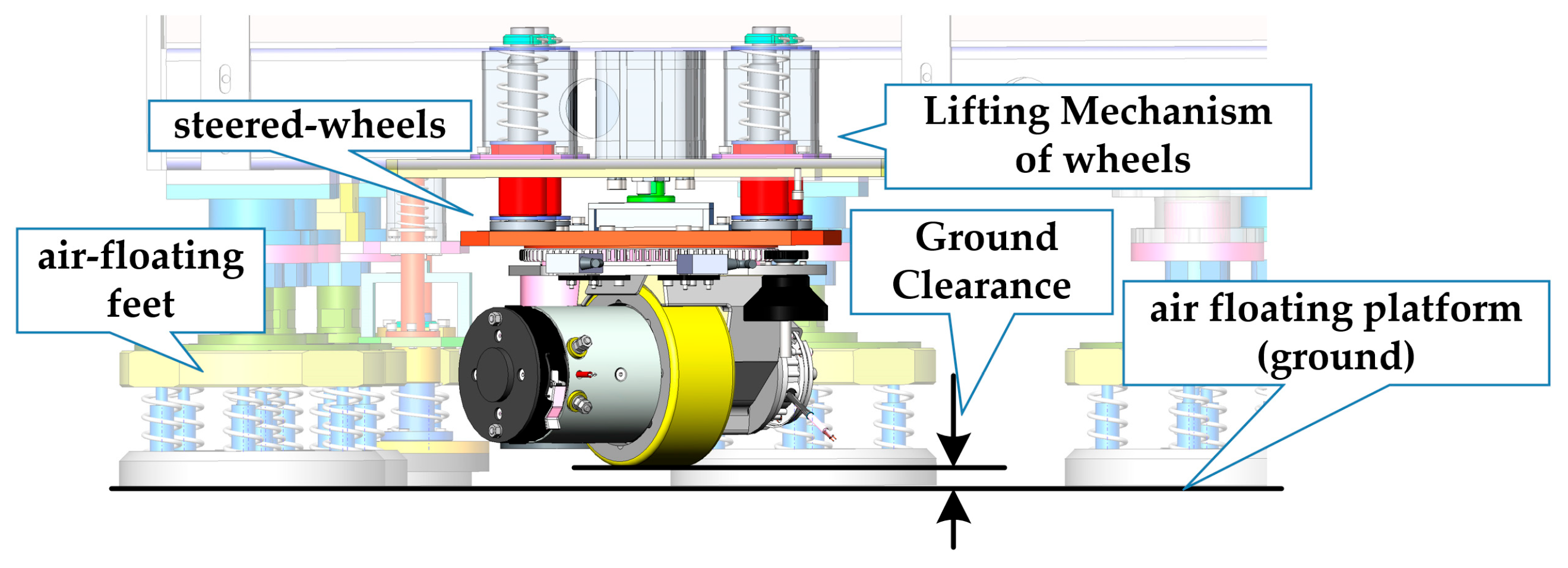
This paper integrates retractable steering wheels within the chassis of the full-physical satellite simulator to enable active propulsion while allowing rapid switching between the wheel-driven and passive air-flotation states. Using the H-simulator as a detailed example: the simulator’s weight is always borne by the air feet, regardless of whether it is in passive flotation or active wheel-driven motion. As shown in Figure 5, the steering wheels are equipped with a lifting mechanism that allows for small vertical displacements. During the passive air-bearing state, the wheels are retracted, losing contact with the platform. When active driving is required, the mechanism lowers the wheels until they contact the air-bearing surface with a predetermined contact pressure. This contact pressure is insufficient to support the simulator’s weight but is adequate to generate the friction necessary for propulsion. In this hybrid state, the majority of the weight remains supported by the air feet, maintaining the micro-gravity simulation, while the wheels provide the required active driving capability.
Here, F W represents the contact force between the steering wheel and the air-bearing surface when engaged. The parameters m and I y ( H ) denote the mass of the simulator and its moment of inertia about the y-axis of the H-frame, respectively. a max and α max represent the maximum linear acceleration and maximum angular acceleration (about the y-axis) achievable by the dual-wheel driving system, respectively. v max and ω max are the maximum linear velocity and maximum angular velocity required for the simulator. r is the radius of gyration of the single steering wheel with respect to the simulator’s axis of inertia.
We will conduct a quantitative analysis of the proposed method combining “steering wheel drive with air-bearing gravity compensation” based on the active motion requirements of the simulated star. This quantitatively demonstrates that the steering wheel usage method described in this paper does not adversely affect the operation of the air-bearing gravity compensation. It illustrates that the key innovation of this paper—“steering wheel drive with air-bearing gravity compensation and switching between active motion and passive air-bearing”—is feasible and can operate stably. The performance limitations for the steering wheel motion that simultaneously satisfy the requirements for active motion control performance and for switching between active motion and passive air-bearing are provided, forming a perfect alignment with the MPC theory mentioned earlier. The simulator’s motion performance requirements and basic hardware parameters are shown in Table 1.
Driving force required to satisfy the maximum acceleration for translational motion of the simulator is
F r e q u i r e d ( H ) = m a max
Driving torque required to satisfy the maximum rotational acceleration of the simulator is
T r e q u i r e d ( H ) = I y ( H ) α max
Considering combined motion, the maximum driving force required per wheel is
F r e q u i r e d ( W ) = 1 2 F r e q u i r e d ( H ) + 1 2 T r e q u i r e d ( H ) r
The air-flotation gravity compensation itself possesses a certain load adaptation capability. Its high stiffness characteristic, manifested in the air film thickness, allows it to operate stably under varying load conditions. Here, we design the normal force between the steering wheel and the air-flotation platform to be 10% of the total mass of the simulated unit. This ensures that the mass disturbance during switching between active motion and passive air-flotation is around 10%. Equation (109) defines the achievable contact force between the steering wheel and the air-bearing plane, under the prerequisite of stable air-bearing system operation. Equation (110) expresses the maximum driving force that the steering wheel can provide. Furthermore, it states that the system proposed in this paper can stably switch between active wheel motion and passive air-bearing mode when the provided driving force exceeds the force required for motion.
F C = 1 2 η 1 m g
F W = η 2 F C F r e q u i r e d ( W )
The maximum velocity and acceleration capability required per wheel to simultaneously satisfy both rotational and translational motion
v r e q u i r e d ( W ) = v max + ω max r
a r e q u i r e d ( W ) = a max + α max r
Integrating the motion velocity and acceleration requirements, Table 2 presents the implemented MPC constraints.
The steering capability of the steering wheel is determined by its own parameters. All the information in Table 2 constitutes the constraint conditions for the MPC controller. The application of MPC allows us to design a receding horizon optimal controller while satisfying the above conditions, thereby optimizing the performance of the closed-loop system. These constraints are derived from both the simulated star’s motion requirements and the requirements for stable switching between active and passive air-flotation modes. This supports our Innovation Points 1 and 4.

4. Results

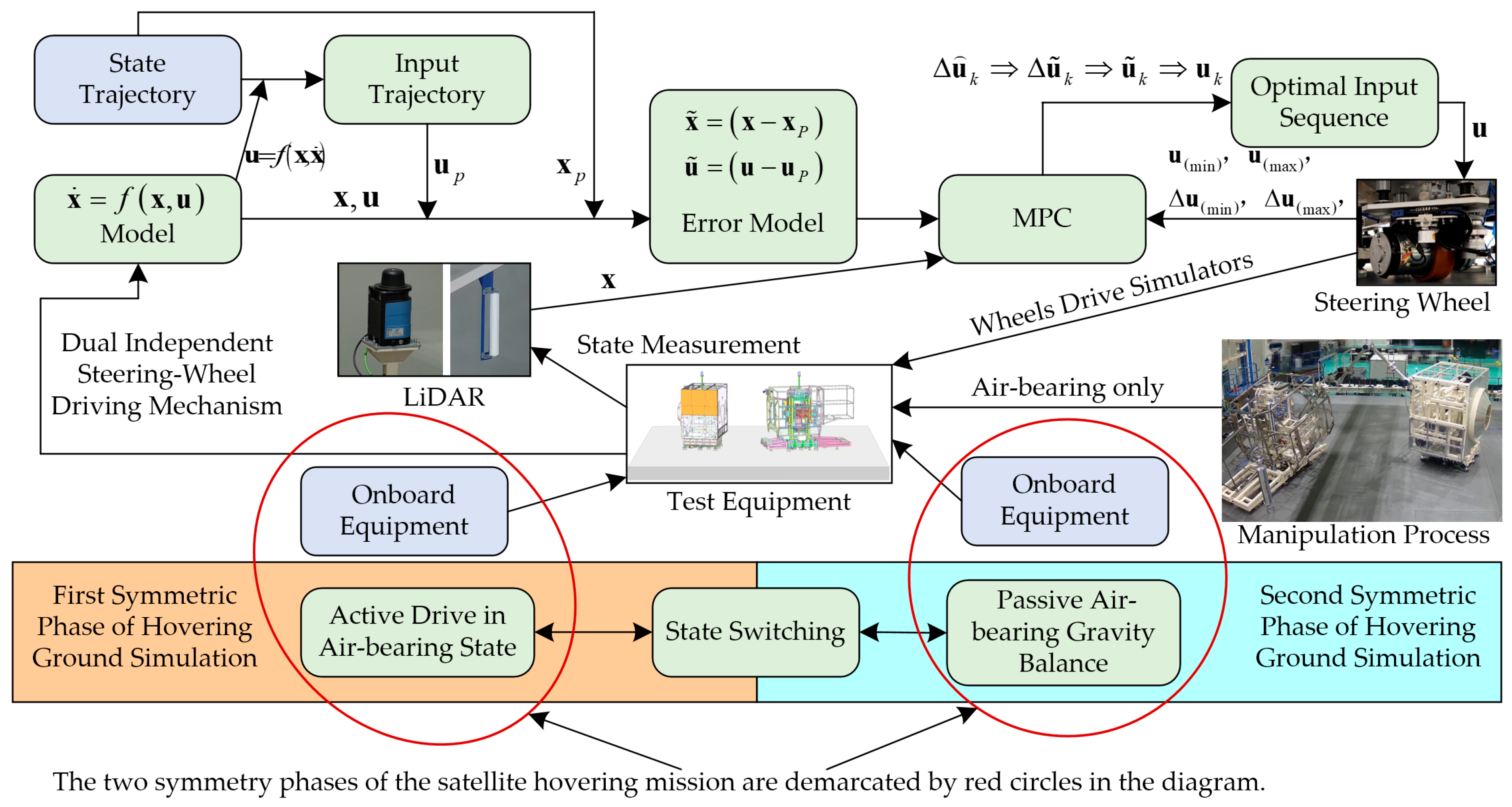
This section presents experimental results from both the active trajectory simulation and passive air-bearing motion phases to validate the proposed ground-testing methodology. The system’s hardware composition is first described, followed by a performance analysis structured according to the two distinct phases of a satellite hovering mission: initial active navigation and subsequent passive micro-gravity dynamics. A block diagram of the experimental setup is shown in Figure 6.
The experimental system possesses the capability to switch between the symmetrical active and passive motion modes, thereby covering the testing requirements for both phases of a satellite hovering mission and providing a testbed for various onboard products. A LiDAR system is employed to measure the system state, while the steering wheels are used to actuate the system and provide active state control. We established a first-principles model of the system. Based on this model and the target satellite hovering trajectory, the reference input trajectory and the error model are derived, enabling the dual-steering-wheel MPC to effectively control the state of the simulator.

4.1. Key Hardware Components

The key hardware is divided into two main parts: first, the system that enables air-bearing micro-gravity simulation and its integrated actuators (the two actively driven steering wheels); second, the LiDAR system for state measurement. As shown in Figure 7, the simulator’s base is equipped with air feet and the retractable steering wheels. The lifting mechanism allows the wheels to be engaged or disengaged, enabling the simulator to switch between passive air-bearing mode and active wheel-driven mode while levitated. Critically, when the wheels are lowered to establish contact with the platform, the air feet remain active and continue to provide levitation. The driving surface of the steering wheels is made of rubber to increase the friction coefficient between the wheels and the air-bearing platform. The wheels are steerable, and the steering angle of each wheel relative to the simulator body is measured by an angular encoder.
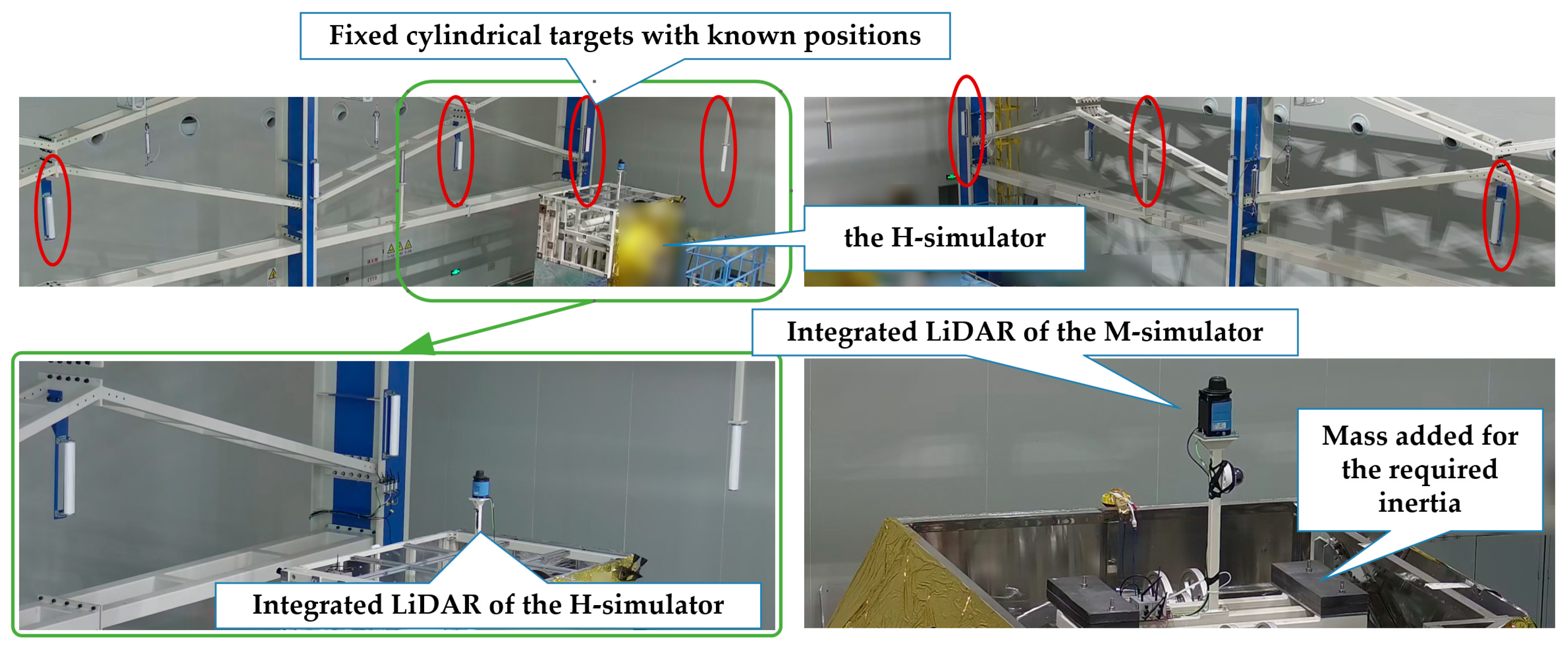
Taking the H-simulator as an example, its system state comprises the x and z coordinates of the H-frame relative to the G-frame, and the rotation angle about the y-axis. These three quantities correspond precisely to the measurements provided by a planar LiDAR system. This work employs LiDAR as the primary state sensor, acquiring the system state for closed-loop trajectory tracking control. The LiDAR determines its own pose relative to the global frame by measuring the distances to n known cylindrical retro-reflective targets fixed in the environment. Subsequently, based on the fixed translational and rotational relationship between the LiDAR frame and the simulator body frame, a coordinate transformation is performed to obtain the pose of the simulator relative to the global frame.
Figure 8 shows some of the fixed cylindrical retro-reflective targets distributed around the perimeter of the test area. The H-simulator and the M-simulator are each rigidly equipped with a LiDAR unit, as illustrated. These LiDAR units cyclically measure their distances to the targets via a scanning pattern, thereby determining their own pose within the global frame. Figure 7 also reveals the presence of counterweight mass blocks installed on top of the M-simulator, which are designed to achieve the moment of inertia matching that of the actual satellite being simulated.

4.2. Active Trajectory Tracking Experimental Results

As described in Figure 1 regarding the experimental setup, the complete satellite navigation testing process comprises active trajectory navigation simulation and passive air-bearing motion. In this section, we present the experimental results of the active trajectory navigation segment, while the passive air-bearing validation will be demonstrated in the subsequent section. During the active phase, the satellite simulator—operating under air-bearing gravity compensation—was actively driven by the proposed dual-steering-wheel mechanism to track a predefined satellite navigation trajectory with attitude requirements.
The key parameters for the MPC controller, as utilized in the experiments, are summarized in Table 3.
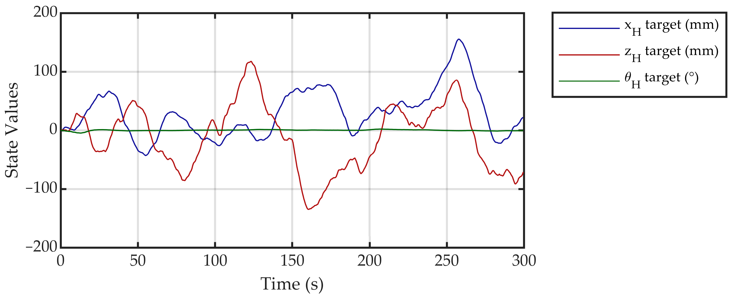
A shorter prediction horizon enhances the accuracy of the linearized model and reduces the computational burden. With the parameters specified in Table 3, the measured average computation time is 0.1 s, utilizing only 20% of the sampling interval. The resulting system performance is described below. The reference trajectory is illustrated in Figure 9.
This is a 300 s satellite hovering trajectory. The system is initialized at the zero state and subsequently follows the prescribed trajectory. As evident from the figure, the trajectory within the air-bearing plane involves not only positional components (x and z) but also a yaw attitude angle component.
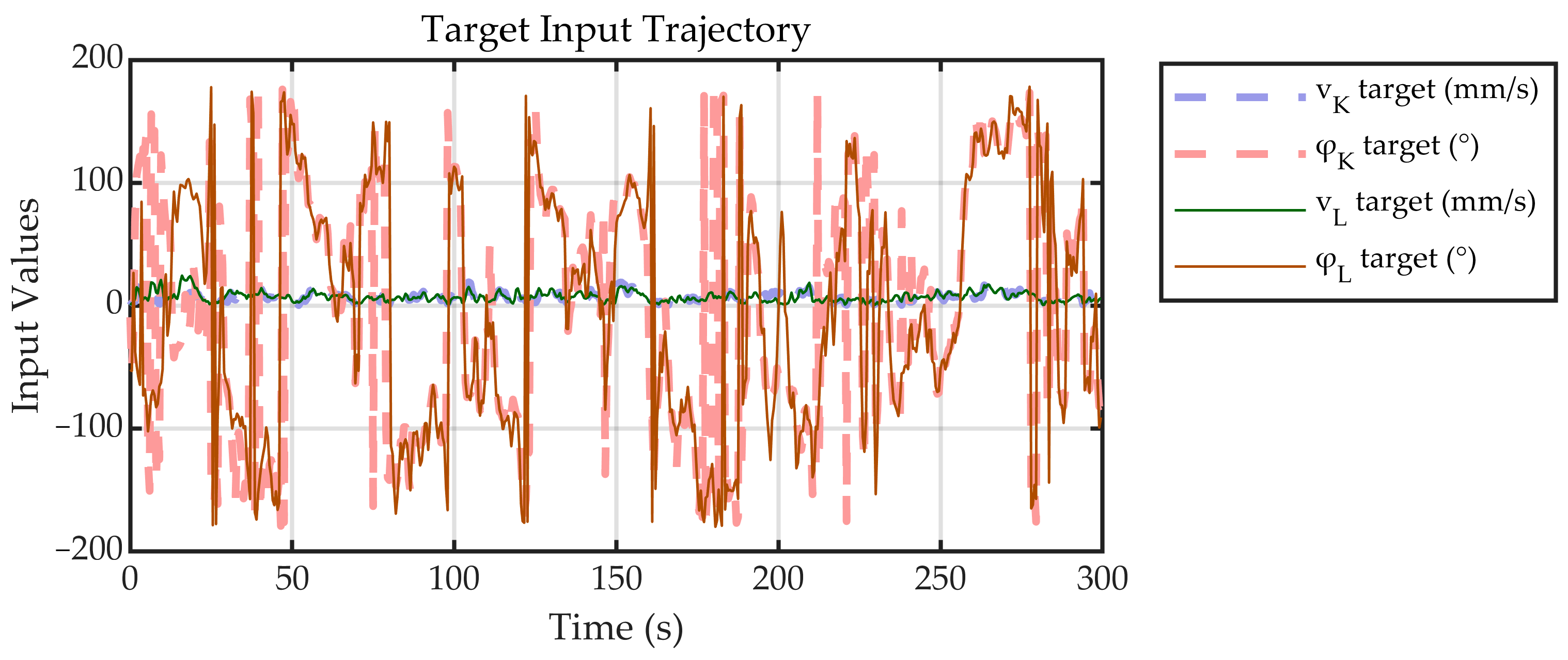
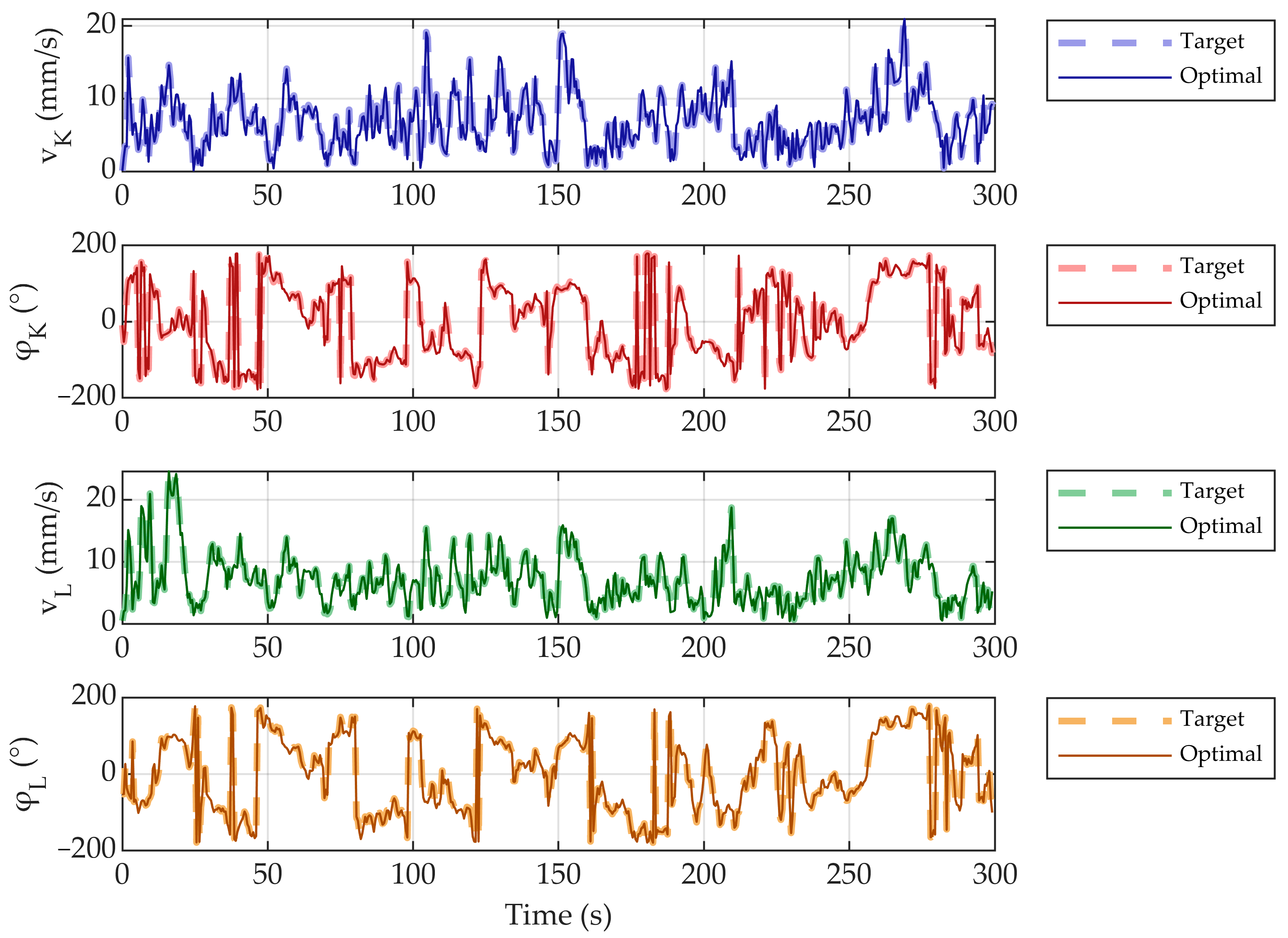
When designing the MPC cost function, it incorporates objectives for optimal tracking of both the system state trajectory and the input trajectory. Based on the determined satellite hovering state profile, we compute the corresponding target input profile, which is shown in Figure 10.
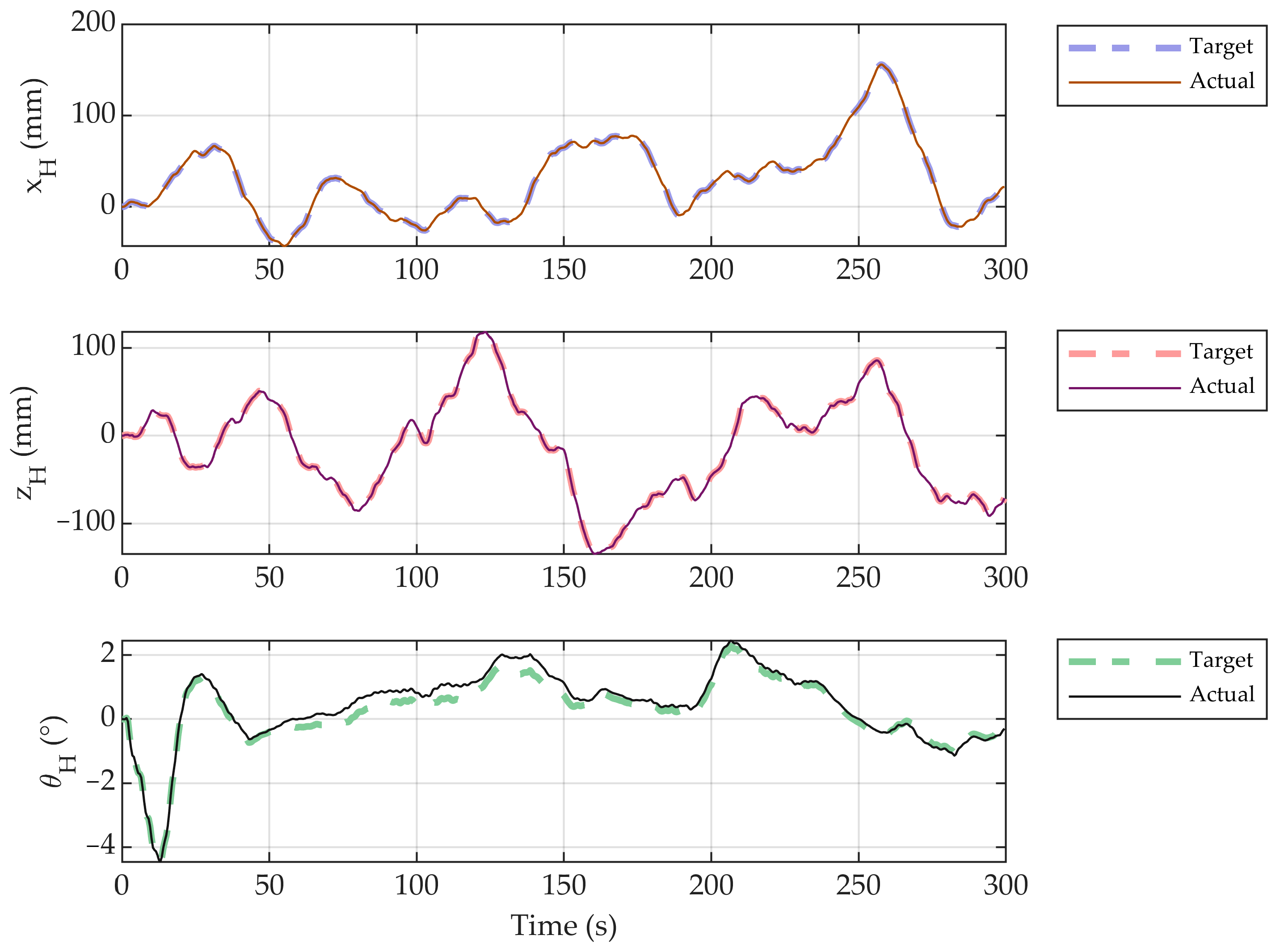
By applying the MPC strategy to the dual-steering-wheel model established in this paper for tracking the satellite hovering trajectory, the resulting system state tracking performance is shown in Figure 11.
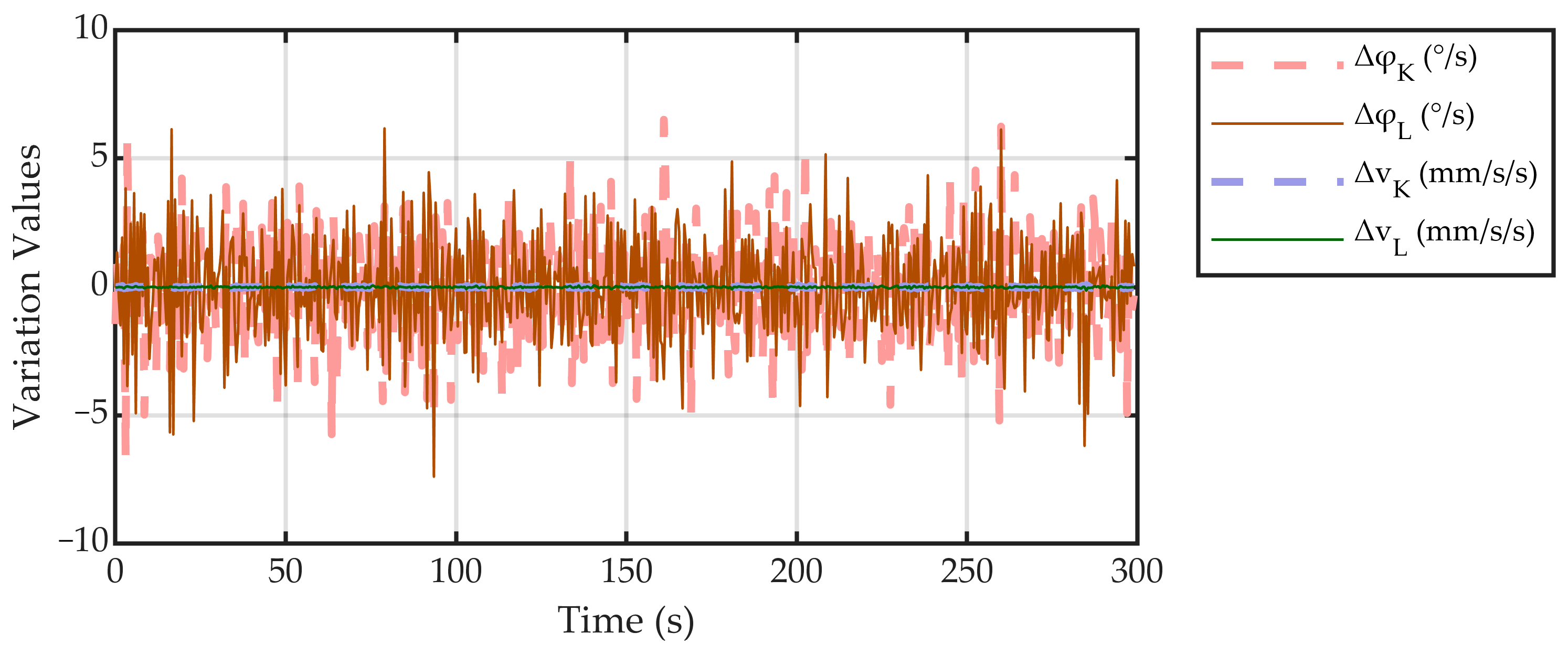
The tracking performance of the controller designed in this paper for the system inputs is shown in Figure 12.
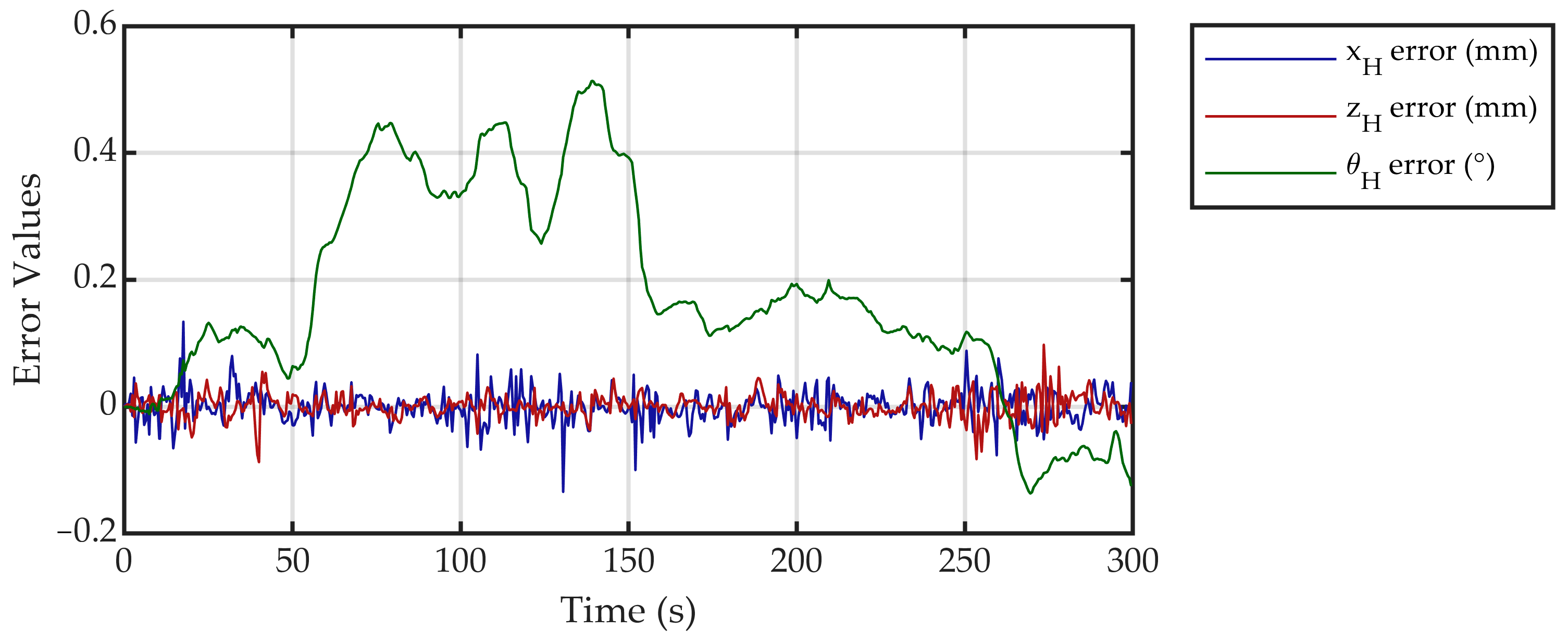
The system state errors are shown in Figure 13.
As can be observed from the error curves, the method proposed in this paper achieves excellent tracking performance for the target satellite hovering trajectory, with the errors stabilizing within an acceptable range.
As shown in Figure 14, the system inputs exhibit stable variations and remain confined within the hardware’s achievable limits. This demonstrates a key value of the MPC: its ability to achieve optimal tracking of the target trajectory while explicitly adhering to the hardware constraints.
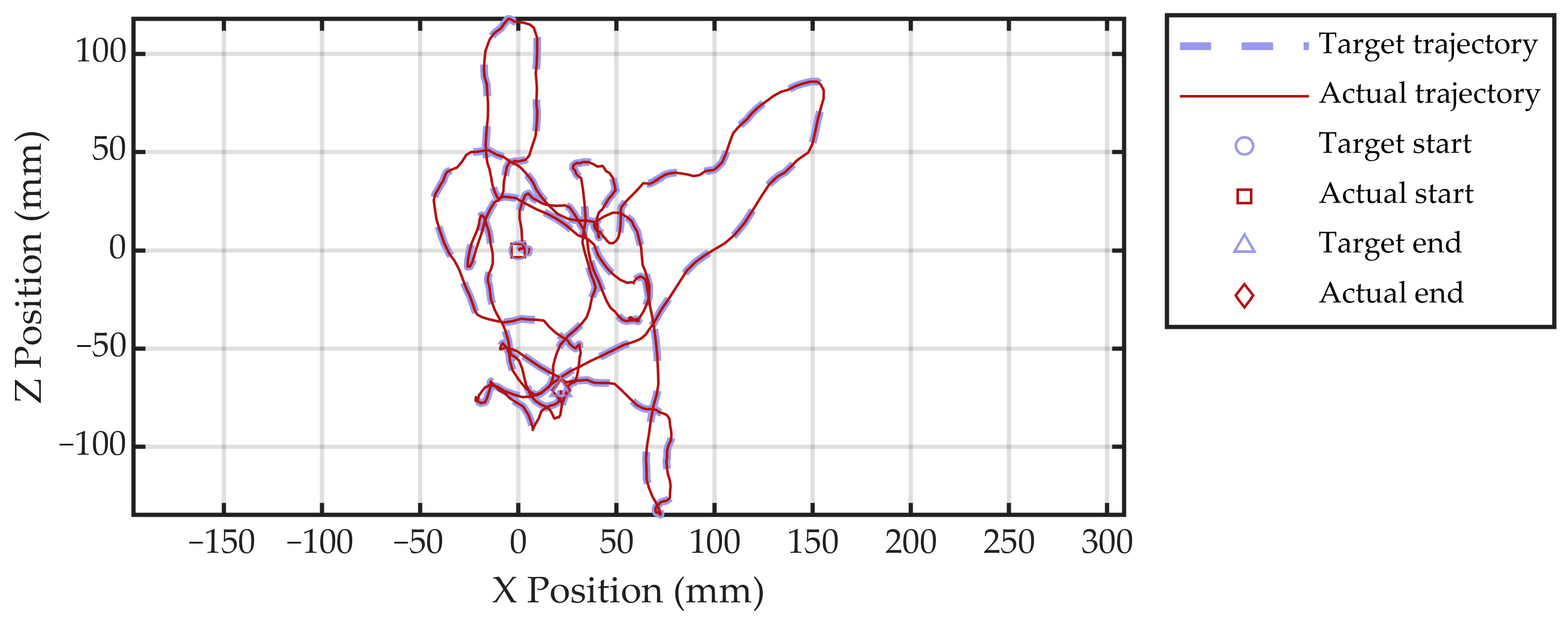
As shown in Figure 15, the target satellite hovering trajectory and the actual executed trajectory are plotted in the XZ plane. The hovering trajectory resembles a pseudo-random path, which increases the difficulty of steering wheel-based tracking. Nevertheless, the actual trajectory demonstrates close agreement with the target, as evident from the results.
These results confirm the accuracy of the kinematic model for the air-bearing simulator driven by dual independent steering wheels, as well as the validity of the trajectory tracking error model, as developed in this paper. The proposed control method successfully enables the air-bearing simulator to actively track the 6-DOF satellite hovering trajectory. Furthermore, it ensures that the wheel’s output driving speed and force comply with the hardware constraints, while also guaranteeing that the steering angles and steering rates remain within their specified physical limits.
The experimental results presented in this subsection directly correspond to the key contributions 1, 2 and 3. Experimental results validate the successful integration of steering wheels with the air-bearing gravity compensation platform for active motion control. The proposed mathematical model demonstrates correctness, while the MPC strategy proves effective in confining trajectory tracking errors to a minimal level and ensuring all outputs remain within design constraints.

4.3. Passive Air-Bearing Simulation Experimental Results

Upon completion of the satellite hovering MPC trajectory tracking phase by the experimental system developed in this work, the system transitions from active attitude control to passive air-bearing gravity compensation. Following this transition, the steering wheels are disengaged from testing operations. The steering wheel control strategies discussed previously become inactive during this phase, as the wheels are mechanically decoupled from the ground. The satellite simulator subsequently operates exclusively under air-bearing gravity compensation. During this operational mode, an onboard robotic arm performs capture operations on another satellite simulator, enabling simulation of in-orbit manipulation tasks. This experimental phase constitutes an integral component of the comprehensive satellite hovering test, which—when combined with the preceding wheel-driven phase—achieves complete ground-based simulation of the entire satellite hovering mission profile.
Remark 3.
Throughout this experimental phase, the robotic arm maintains cable-suspended gravity compensation. Residual gravity effects from the suspension system are considered negligible. The suspension-based gravity compensation methodology for the robotic arm falls beyond the scope of this paper, which focuses exclusively on the manipulation target—the satellite simulator operating under passive air-bearing gravity compensation—acting as the dynamic load for the robotic arm.
The states of both the H and M simulators are recorded throughout this process, and the corresponding data curves are plotted.
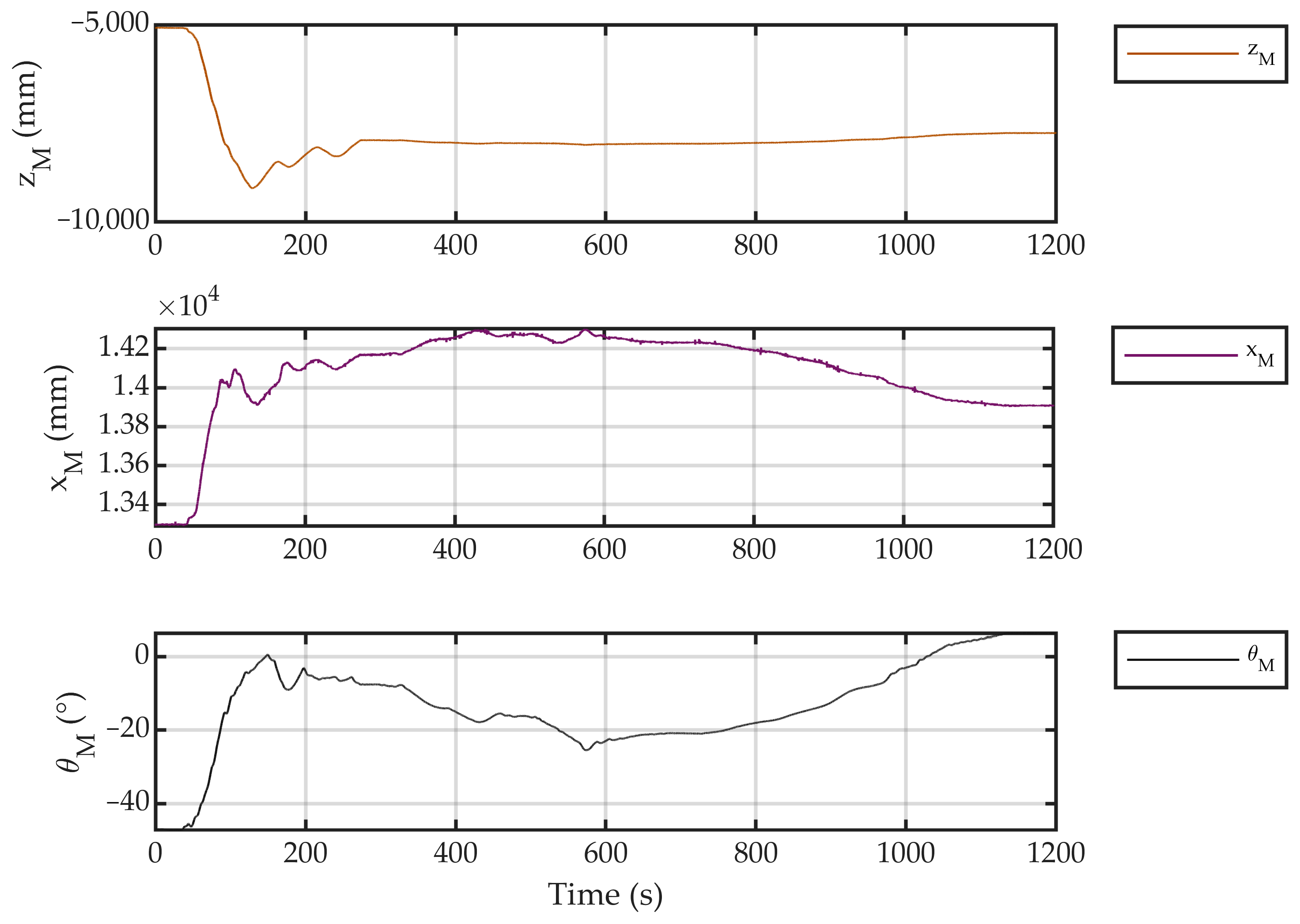
As shown in Figure 16, the state curves of the H-simulator during the passive micro-gravity test are presented. The test was conducted on an air-bearing platform approximately 20 m by 15 m in size, with the global coordinate frame established at one corner of the platform. The data reveals that throughout the test, the H-simulator’s position varied within a range of 7 to 10 m along the x-axis and 6 to 10 m along the z-axis, while its orientation underwent changes exceeding 100 degrees.
The experimental states of the M-simulator are shown in Figure 17. Its behavior is quite similar to that of the H-simulator: its x-position ranges between 13 m and 15 m; its z-position covers a broader span from 5 m to 10 m; and its rotation is relatively smaller, varying around 50 degrees. The M-simulator, having a larger moment of inertia than the H-simulator, exhibited a smaller angular displacement when subjected to internal forces within the combined system. This observed behavior is a clear indicator of high-fidelity micro-gravity simulation.
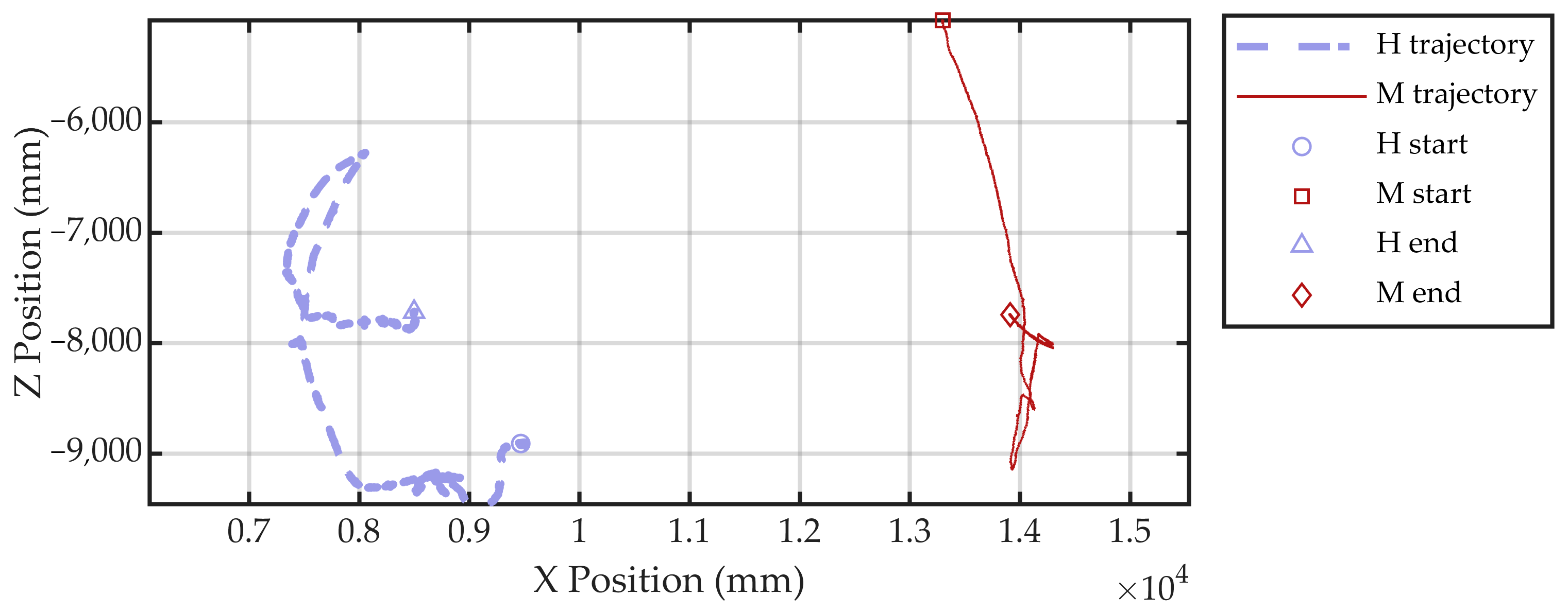
For a clearer perspective, the XZ plane trajectories of both simulators are plotted together in Figure 18. It can be observed that during this experimental run, both simulators operated within their respective spatial domains, maintaining a relative distance of over 3 m between them. These operational data demonstrate that the proposed ground-testing methodology for the entire satellite hovering mission profile successfully and effectively emulates the test scenario on the ground.
The experimental results presented in this subsection directly correspond to the key contributions 1 and 4. The tests confirm that the introduction of the steering wheels does not compromise the air-bearing gravity compensation. Under the carefully designed switching conditions presented in this work, the simulator successfully transitions from active motion to passive air-flotation while maintaining stable operation.

5. Discussion

This paper presents a novel ground-testing platform that integrates dual independent steering wheels with MPC-based trajectory tracking to achieve comprehensive satellite hovering simulation. The platform’s core innovation lies in its seamless switching capability between active driving and passive air-bearing states, enabling full-mission emulation. The contributions of this work are systematically demonstrated through both theoretical development and experimental validation:
This study has implemented a novel wheeled actuation system for spacecraft ground testing by integrating active steering-wheel drive with passive air-bearing gravity compensation. The platform has successfully achieved seamless switching between active driving and passive floating modes within a unified hardware setup.
We have extended conventional wheeled vehicle models to a configuration where each wheel features independent steering capability. The kinematic model for this multi-wheel independent steering mechanism has been established, with explicit characterization of its operational constraints.
We have developed a Model Predictive Control (MPC) framework for satellite hovering trajectory tracking using dual independent steering wheels. Our approach is formulated using an attitude-included trajectory tracking error model. The implemented controller has demonstrated good tracking performance in experiments, maintaining state errors within 2.5% of the operational range while satisfying all hardware constraints.
Experimental results demonstrate that the proposed active-passive switching method is practically effective, while the application of Model Predictive Control (MPC) ensures strict adherence to all system constraints. Furthermore, the platform’s micro-gravity simulation capability has been experimentally validated through extended 1200 s passive flotation tests, confirming stable operation and expected state behavior.
This paper has successfully demonstrated ground-based simulation tests for satellite hovering tasks using a comprehensive physical simulator with air-bearing and active/passive motion-switching capabilities. Building upon this foundation, the platform holds significant potential to provide ground verification support for future on-orbit validation missions. A key prospect involves its integration with Hardware-in-the-Loop (HIL) simulation, enabling the verification of space robotic arm operations and control algorithms in a microgravity environment through a combined approach of full-physical and semi-physical testing. Furthermore, by increasing the number of simulators and leveraging the platform’s active motion capabilities, a multi-platform cooperative test system can be established for the simulation and validation of satellite formation-flying missions. In summary, the platform developed in this study expands the application scope of full-physical air-bearing gravity compensation technology. Future work will focus on exploiting its passive full-physical testing and active motion capabilities as central pillars for further research and development.

Author Contributions

Conceptualization, X.Z.; methodology, X.Z.; validation, X.Z.; formal analysis, Z.Z., Z.X. and Z.J.; investigation, Y.T.; resources, Z.Z., Z.X. and Z.J.; data curation, Y.T.; writing—original draft preparation, X.Z. and Z.Z.; writing—review and editing, X.Z. and Z.Z.; supervision, Z.J. and Z.X.; project administration, Z.Z. and Z.X.; funding acquisition, Z.J. and Z.X. All authors have read and agreed to the published version of the manuscript.

Funding

This research was funded in part by the nsfc under Grant 52575012; in part by the Liaoning Provincial Natural Science Foundation under Grant 2025-MS-084; and in part by the Youth Program of the Basic Research Plan, Shenyang Institute of Automation, Chinese Academy of Sciences under Grant 2023JC1K11.

Data Availability Statement

Data is contained within the article.

Conflicts of Interest

The authors declare no conflicts of interest.

Abbreviations

The following abbreviations are used in this manuscript:
MPCModel Predictive Control
NMPCNonlinear Model Predictive Control

References

  1. Zhao, C.; Maestrini, M.; Di Lizia, P. Low-thrust optimal control of spacecraft hovering for proximity operations. J. Guid. Control Dyn. 2024, 47, 1457–1469. [Google Scholar] [CrossRef]
  2. Lee, D.; Vukovich, G. Adaptive finite-time control for spacecraft hovering over an asteroid. IEEE Trans. Aerosp. Electron. Syst. 2016, 52, 1183–1196. [Google Scholar] [CrossRef]
  3. Ma, X.; Gong, S.; Cheng, L. Autonomous Vision-Based Control for Spacecraft Navigation Around an Asteroid. IEEE Trans. Aerosp. Electron. Syst. 2025, 61, 10649–10662. [Google Scholar] [CrossRef]
  4. Lin, Z.; Wu, B. Image-Based Multispacecraft Feature Tracking Control Under Visibility Constraints with Observer. IEEE Trans. Aerosp. Electron. Syst. 2024, 60, 8069–8085. [Google Scholar] [CrossRef]
  5. Chen, N.; Zhang, Y.; Li, Z.; Cheng, W.; Li, J.; Diao, H.; Wang, W.; Fang, Y. An Improved Sampling-Based Approach for Spacecraft Proximity Operation Path Planning in Near-Circular Orbit. IEEE Access 2020, 8, 41794–41804. [Google Scholar] [CrossRef]
  6. Lin, Z.; Wu, B.; Wang, D. Specific Tracking Control of Rotating Target Spacecraft Under Safe Motion Constraints. IEEE Trans. Aerosp. Electron. Syst. 2023, 59, 2422–2438. [Google Scholar] [CrossRef]
  7. Shao, J.; Zhou, Q.; Ye, D.; Bernelli-Zazzera, F.; Sun, Z. Feasibility Analysis and Synchronization Control for Underactuated Spacecraft Formation Hovering. IEEE Trans. Control Syst. Technol. 2024, 32, 241–249. [Google Scholar] [CrossRef]
  8. Shao, J.; Su, B.; Zhou, Q.; Ye, D.; Sun, Z. Formation reconfiguration hovering technique for underactuated satellite. In Proceedings of the 2021 5th Chinese Conference on Swarm Intelligence and Cooperative Control, Shenzhen, China, 19–22 November 2021; Springer: Berlin/Heidelberg, Germany, 2022. [Google Scholar]
  9. Cao, Y.; Mu, J.; Cheng, X.; Liu, F. Spacecraft-DS: A Spacecraft Dataset for Key Components Detection and Segmentation via Hardware-in-the-Loop Capture. IEEE Sens. J. 2024, 24, 5347–5358. [Google Scholar] [CrossRef]
  10. Duan, G.; Liu, G.P.; Pang, Z.H. Identification of Unknown Inertia Parameters of Spacecraft and Spacecraft Hovering. In Proceedings of the 2021 40th Chinese Control Conference (CCC), Shanghai, China, 26–28 July 2021. [Google Scholar]
  11. Elmorshedy, M.F.; Xu, W.; El-Sousy, F.F.M.; Islam, R.; Ahmed, A.A. Recent Achievements in Model Predictive Control Techniques for Industrial Motor: A Comprehensive State-of-the-Art. IEEE Access 2021, 9, 58170–58191. [Google Scholar] [CrossRef]
  12. Huang, X.; Zha, Y.; Lv, X.; Quan, X. Torque Fault-Tolerant Hierarchical Control of 4WID Electric Vehicles Based on Improved MPC and SMC. IEEE Access 2023, 11, 132718–132734. [Google Scholar] [CrossRef]
  13. Zhao, H.; Yang, H.; Wang, Z.; Xia, Y. Nonlinear MPC on Parallel Parking for Autonomous Vehicles Under State-Dependent Switching. IEEE Trans. Autom. Sci. Eng. 2025, 22, 6377–6387. [Google Scholar] [CrossRef]
  14. Hassan, A.; Ruiz-Moreno, S.; Frejo, J.R.D.; Maestre, J.M.; Camacho, E.F. Neural-Network Based MPC for Enhanced Lateral Stability in Electric Vehicles. IEEE Access 2024, 12, 23265–23278. [Google Scholar] [CrossRef]
  15. Tagliabue, A.; How, J.P. Efficient Deep Learning of Robust Policies From MPC Using Imitation and Tube-Guided Data Augmentation. IEEE Trans. Robot. 2024, 40, 4301–4321. [Google Scholar] [CrossRef]
  16. Hanover, D.; Foehn, P.; Sun, S.; Kaufmann, E.; Scaramuzza, D. Performance, Precision, and Payloads: Adaptive Nonlinear MPC for Quadrotors. IEEE Robot. Autom. Lett. 2022, 7, 690–697. [Google Scholar] [CrossRef]
  17. Gomaa, M.A.K.; Silva, O.D.; Mann, G.K.I.; Gosine, R.G. Nonlinear MPC Without Terminal Costs or Constraints for Multi-Rotor Aerial Vehicles. IEEE Control Syst. Lett. 2022, 6, 440–445. [Google Scholar] [CrossRef]
  18. Bauersfeld, L.; Spannagl, L.; Ducard, G.J.J.; Onder, C. MPC Flight Control for a Tilt-Rotor VTOL Aircraft. IEEE Trans. Aerosp. Electron. Syst. 2021, 57, 2395–2409. [Google Scholar] [CrossRef]
  19. Wang, J.; Zhou, X.; Chen, X.; Wang, Z.; Wang, P.; Liu, E. Development of HIL—Real vehicle dual steering wheel test platform for automotive SBW system based on variable transmission ratio control. In Proceedings of the International Conference on Electric Vehicle and Vehicle Engineering (CEVVE 2023), Shenzhen, China, 10–12 November 2023. [Google Scholar]
  20. Quartullo, R.; Bianchini, G.; Garulli, A.; Giannitrapani, A. Robust Output Feedback Variable-Horizon MPC with Adaptive Terminal Constraints. IEEE Control Syst. Lett. 2025, 9, 883–888. [Google Scholar] [CrossRef]
  21. Chuah, J.; Liang, X.; Ge, S.S. Nonlinear Model Predictive Control of a Dual-Axis Tilting Quadcopter. In Proceedings of the 2023 IEEE International Conference on Cybernetics and Intelligent Systems (CIS) and IEEE Conference on Robotics, Automation and Mechatronics (RAM), Penang, Malaysia, 9–12 June 2023. [Google Scholar]
  22. Jin, R.; Li, L.; Liang, X.; Zou, X.; Yang, Z.; Ge, S.S.; Huang, H. Energy-efficient design of the powertrain for mechanical-electro-hydraulic equipment via configuring multidimensional controllable variables. Renew. Sustain. Energy Rev. 2024, 201, 114511. [Google Scholar] [CrossRef]
  23. Singh, V.K.; Tripathi, R.N.; Hanamoto, T. Implementation Strategy for Resource Optimization of FPGA-Based Adaptive Finite Control Set-MPC Using XSG for a VSI System. IEEE J. Emerg. Sel. Top. Power Electron. 2021, 9, 2066–2078. [Google Scholar] [CrossRef]
  24. Jeong, C.; Brastein, O.M.; Skeie, N.O.; Sharma, R. Hybrid Model Predictive Control Scheme for Controlling Temperature in Building Under Uncertainties. IEEE Access 2023, 11, 116820–116832. [Google Scholar] [CrossRef]
  25. Domański, P.D.; Ławryńczuk, M. Impact of MPC Embedded Performance Index on Control Quality. IEEE Access 2021, 9, 24787–24795. [Google Scholar] [CrossRef]
  26. Pang, S.; Zhang, Y.; Huangfu, Y.; Li, X.; Tan, B.; Li, P.; Tian, C.; Quan, S. A Virtual MPC-Based Artificial Neural Network Controller for PMSM Drives in Aircraft Electric Propulsion System. IEEE Trans. Ind. Appl. 2024, 60, 3603–3612. [Google Scholar] [CrossRef]
  27. Huang, K.; Wei, K.; Li, F.; Yang, C.; Gui, W. LSTM-MPC: A Deep Learning Based Predictive Control Method for Multimode Process Control. IEEE Trans. Ind. Electron. 2023, 70, 11544–11554. [Google Scholar] [CrossRef]
  28. Zanon, M.; Gros, S. Safe Reinforcement Learning Using Robust MPC. IEEE Trans. Autom. Control 2021, 66, 3638–3652. [Google Scholar] [CrossRef]
  29. Tsukamoto, H.; Chung, S.J. Neural Contraction Metrics for Robust Estimation and Control: A Convex Optimization Approach. IEEE Control Syst. Lett. 2021, 5, 211–216. [Google Scholar] [CrossRef]
  30. Najafqolian, M.A.; Alipour, K.; Mousavifard, R.; Tarvirdizadeh, B. Control of Aerial Robots Using Convex QP LMPC and Learning-Based Explicit-MPC. IEEE Trans. Ind. Inform. 2024, 20, 10883–10891. [Google Scholar] [CrossRef]
  31. Zhang, B.; Zhao, W.; Luan, Z.; Wang, C.; Zhou, X.; Wu, H. An Antirollover Control Strategy Based on Time-Varying Nonlinear MPC for Three-Axle Steering/Braking-by-Wire Vehicle. IEEE Trans. Ind. Electron. 2024, 71, 11048–11060. [Google Scholar] [CrossRef]
  32. You, Y.; Yang, Z.; Zhuo, H.-Z.; Xu, N.; Liao, L.; Jiang, W. Design of an adaptive MPC control system for unmanned ground vehicle based on FP-ADMM and RBFNN. Control Eng. Pract. 2025, 164, 106399. [Google Scholar] [CrossRef]
  33. Dong, F.; Li, X.; You, K.; Song, S. Standoff Tracking Using DNN-Based MPC with Implementation on FPGA. IEEE Trans. Control Syst. Technol. 2023, 31, 1998–2010. [Google Scholar] [CrossRef]
  34. Wang, H.; Liu, B.; Ping, X.; An, Q. Path Tracking Control for Autonomous Vehicles Based on an Improved MPC. IEEE Access 2019, 7, 161064–161073. [Google Scholar] [CrossRef]
  35. Dixit, S.; Montanaro, U.; Dianati, M.; Oxtoby, D.; Mizutani, T.; Mouzakitis, A.; Fallah, S. Trajectory Planning for Autonomous High-Speed Overtaking in Structured Environments Using Robust MPC. IEEE Trans. Intell. Transp. Syst. 2020, 21, 2310–2323. [Google Scholar] [CrossRef]
  36. Eltrabyly, A.; Ichalal, D.; Mammar, S. Quadcopter Trajectory Tracking in the Presence of 4 Faulty Actuators: A Nonlinear MHE and MPC Approach. IEEE Control Syst. Lett. 2022, 6, 2024–2029. [Google Scholar] [CrossRef]
  37. Wilde, M.; Clark, C.; Romano, M. Historical survey of kinematic and dynamic spacecraft simulators for laboratory experimentation of on-orbit proximity maneuvers. Prog. Aerosp. Sci. 2019, 110, 100552. [Google Scholar] [CrossRef]
  38. Chu, M.; Lin, S.; Xu, S.; Wang, G.; Jia, J.; Chang, R. An Omnidirectional Compliant Docking Strategy for Non-Cooperative On-orbit Targets: Principle, Design, Modeling, and Experiment. IEEE Trans. Aerosp. Electron. Syst. 2024, 60, 8364–8379. [Google Scholar] [CrossRef]
  39. Chen, M.; Zhang, C.; Ping, S.; Ren, Y.; Duan, L.; Kang, Q. Similarity Analysis of an Air-bearing Simulator Reproducing Drag-free Control Dynamics. In Proceedings of the 2024 IEEE 25th China Conference on System Simulation Technology and Its Application (CCSSTA), Tianjin, China, 21–23 July 2024. [Google Scholar]
  40. Mamani, J.G.C.; Wang, X.; Yanyachi, P.R. Automatic Mass Balancing of a Small Spherical Simulator for Attitude Control Verification. IEEE Access 2024, 12, 114465–114479. [Google Scholar] [CrossRef]
  41. Chen, R.; Wang, J.; Zhou, H.; Bai, Y.; Zhao, Y.; Chen, X. Path Planning and Control for Multiagent Traversing Numerous Obstacles. IEEE Trans. Ind. Electron. 2025, 72, 2938–2947. [Google Scholar] [CrossRef]
  42. Zhang, D.W.; Liu, G.P. Secure Predictive Control for Networked High-Order Fully Actuated Systems Under Random DoS Attacks. IEEE Trans. Ind. Inform. 2024, 20, 6935–6945. [Google Scholar] [CrossRef]
  43. Li, Z.; Liu, L.; Xing, X.; Yan, Z.; Liu, Y.; Sun, H. Electromagnetic Characteristics and Modal Analysis of Multi-DOF Motors with Air-Floation. IEEE Access 2022, 10, 53164–53174. [Google Scholar] [CrossRef]
  44. Li, Z.; Yang, K.; Wang, X. Electromagnetic and Flow Field Analysis of Multi-DOF Motor with Air Bearing Structure. IEEE Trans. Appl. Supercond. 2021, 31, 5204504. [Google Scholar] [CrossRef]
  45. Zhang, F.; Huang, Q.; Cheng, R.; Zhang, L.; Li, H.; Li, R.; Pan, Q. Development of a Driving and Control System of Large Stroke 3-D Air-Floating Motion Stage with Submicrometer-Scale Positioning Accuracy. IEEE Sens. J. 2024, 24, 2558–2567. [Google Scholar] [CrossRef]
  46. Zhang, D.W.; Liu, G.P.; Cao, L. Constrained Cooperative Control for High-Order Fully Actuated Multiagent Systems with Application to Air-Bearing Spacecraft Simulators. IEEE/ASME Trans. Mechatron. 2023, 28, 1570–1581. [Google Scholar] [CrossRef]
  47. Zhang, D.W.; Liu, G.P. Secure Tracking Control of Cyber-Physical Systems Against Hybrid Attacks via FAS Terminal Sliding-Mode Predictive Control. IEEE Trans. Cybern. 2025, 55, 5177–5188. [Google Scholar] [CrossRef] [PubMed]
  48. Chen, P.; Gan, H.; Liu, Y.; Luo, Y. Active Disturbance Rejection Fractional-Order Independent Control of Time Delay Systems with Application to Air Floating Motion Platform. IEEE Trans. Instrum. Meas. 2024, 73, 7500410. [Google Scholar] [CrossRef]
  49. Gao, Y.; Li, W.; Ma, R.; Ma, G.; Xia, H. Spacecraft dynamics full-physical simulator based on air bearing technology. In Proceedings of the IECON 2020 the 46th Annual Conference of the IEEE Industrial Electronics Society, Singapore, 18–21 October 2020. [Google Scholar]
  50. Zhao, M.; Hong, W.; Ma, Y.; Bai, Y.; Zhou, Z. Satellite Simulator for Demonstration of Space Laser Tracking. In Proceedings of the 2022 IEEE 17th Conference on Industrial Electronics and Applications (ICIEA), Chengdu, China, 16–19 December 2022. [Google Scholar]
  51. Chavan, R.A.; Seigler, T.M.; Hoagg, J.B. Small-Satellite Attitude Control Using Continuous Sinusoids with Strict Amplitude Constraints. IEEE Trans. Control Syst. Technol. 2023, 31, 707–721. [Google Scholar] [CrossRef]
  52. Jamshidi, S.; Mirzaei, M.; Malekzadeh, M. Applied Optimal Control of Spacecraft Simulator Subject to Failures of Reaction Wheels. Arab. J. Sci. Eng. 2024, 49, 1697–1712. [Google Scholar] [CrossRef]
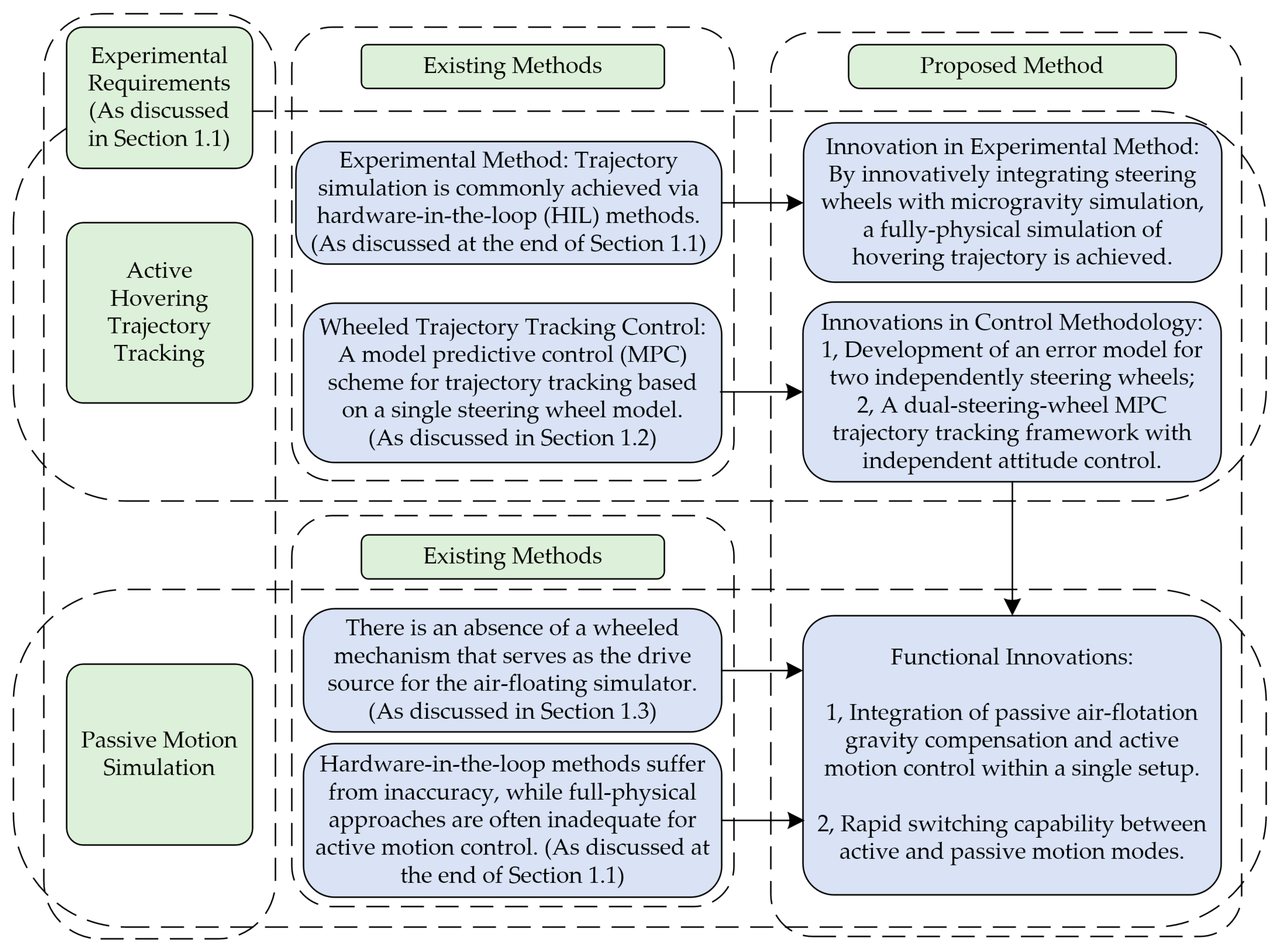
Figure 1. Comparison Between the Existing and Proposed Methods.
Symmetry 17 01990 g001
Figure 2. Testing Platform for Satellite Hovering Simulation.
Symmetry 17 01990 g002
Figure 3. Operating Principle of a Dual-Steering-Wheel Drive.
Symmetry 17 01990 g003
Figure 4. Air Flotation Method for Micro-Gravity Simulation.
Symmetry 17 01990 g004
Figure 5. Switching Between Active Driving and Passive Motion of the Air-Floating Simulator.
Symmetry 17 01990 g005
Figure 6. Architecture of the Experimental System.
Symmetry 17 01990 g006
Figure 7. Air-Feet and Driving Steering Wheels.
Symmetry 17 01990 g007
Figure 8. Lidar and Cylindrical Retroreflectors.
Symmetry 17 01990 g008
Figure 9. Target State Trajectory of the H-Simulator in Satellite Hovering target states.
Symmetry 17 01990 g009
Figure 10. Target Input Trajectory of the H-Simulator in Satellite Hovering.
Symmetry 17 01990 g010
Figure 11. State Trajectory Tracking Performance of the H-Simulator.
Symmetry 17 01990 g011
Figure 12. Input comparison.
Symmetry 17 01990 g012
Figure 13. Input Trajectory Tracking Performance of the H-Simulator.
Symmetry 17 01990 g013
Figure 14. Input Variation in the H-Simulator.
Symmetry 17 01990 g014
Figure 15. xz_Plane View of Satellite Hovering Trajectory Tracking.
Symmetry 17 01990 g015
Figure 16. H-Simulator State during Passive Air-Floating.
Symmetry 17 01990 g016
Figure 17. M-Simulator State during Passive Air-Floating.
Symmetry 17 01990 g017
Figure 18. xz-Plane Trajectories State during Passive Air-Floating.
Symmetry 17 01990 g018
Table 1. Simulator’s Motion Performance Requirements and Basic Hardware Parameters.
Variable DescriptionSymbolValueUnits
Max. linear velocity of the simulator v max 30mm/s
Max. linear acceleration of the simulator a max 60mm/s2
Max. angular velocity of the simulator ω max 1°/s
0.018rad/s
Max. angular acceleration of the simulator α max 2°/s2
0.035rad/s2
Mass of the simulator m 3000kg
Moment of inertia of the simulator I y ( H ) 2000kg·m2
Required max. acceleration force of the simulator F r e q u i r e d ( H ) 180N
Required max. acceleration torque of the simulator T r e q u i r e d ( H ) 70Nm
Driving force required per wheel F r e q u i r e d ( W ) 140N
Contact force per wheel F C 1500N
Driving force Generated per wheel F W 150N
Approx. radius of gyration (per wheel) r 700mm
Load-fluctuation rate for stable operation η 1 0.1
Friction coefficient η 2 0.1
Table 2. MPC constraints for both motion requirements and mode-switching requirements.
Variable DescriptionSymbolValueUnits
Required max. velocity per wheel v r e q u i r e d ( W ) 43mm/s
Required max. acceleration per wheel a r e q u i r e d ( W ) 85mm/s2
Velocity limit of the wheel v l i m ( W ) 50mm/s
Acceleration limit of the wheel a l i m ( W ) 100mm/s2
Steering angle range limit of the wheel ϕ lim 360°
Steering speed limit of the wheel ϕ ˙ lim 90°/s
Table 3. MPC Parameters.
Variable DescriptionSymbolValue
Prediction horizon N p 10
Control horizon N c 1
Sampling time d t 0.5 s
State weighting matrix Q I 3 n
Control weighting matrix R I 4 n
Disclaimer/Publisher’s Note: The statements, opinions and data contained in all publications are solely those of the individual author(s) and contributor(s) and not of MDPI and/or the editor(s). MDPI and/or the editor(s) disclaim responsibility for any injury to people or property resulting from any ideas, methods, instructions or products referred to in the content.