Abstract
One-cycle control (OCC) is prized in power converter applications for its rapid dynamic response and effective disturbance suppression. While its core principle relies on the symmetry of the volt-second value of the inductor in each cycle, recent research shows that embedding a composite function can significantly expand the stable parameter domain of conventional OCC. This paper seeks to identify the optimal function for this enhancement. The logarithmic and arc-tangent functions are selected based on the required characteristics and analyzed using a state-space average model. Analysis of the stability boundaries demonstrates that with embedded, the stability region of is effectively enlarged to more than . With embedded, the stability region of is effectively enlarged to infinity. Therefore, embedding can achieve optimal results, so it is considered the optimal function. This conclusion is conclusively validated by both simulation and experimental results.
1. Introduction
One-cycle control (OCC) offers significant advantages in power electronics, primarily due to its ability to reject input voltage disturbances and achieve exceptional dynamic response within a single switching cycle. Therefore, it plays an important role in applications such as DC-DC converters, inverters, and power factor correction [1,2,3]. Due to the high frequency action of the switch, OCC converters exhibit bifurcation and other nonlinear behaviors, similar to converters based on other control methods. These nonlinear behaviors, such as Hopf bifurcation, period-doubling bifurcation, and even chaos, can significantly impact the stability and performance of converters. Therefore, the nonlinear characteristics of converters should be thoroughly analyzed, and an effective method to control the bifurcation and chaotic phenomena needs to be explored.
Over the past few decades, along with the development of nonlinear dynamic theory and analytic procedures, the existence of different dynamic behaviors, such as Hopf bifurcation, sub-harmonic oscillation, and chaos, have been confirmed to appear in converters, and a set of control strategies has been developed to control them. In [4], a constant on-time one-cycle-controlled boost converter operating in continuous conduction mode was analyzed using the discrete-time model. It was found that Neimark–Sacker bifurcation occurs as the constant on-time value increases. Moreover, based on stability analysis, an additional current loop was developed, extending the stable region. Under certain operating and parameters conditions, it was confirmed that bifurcation and chaotic nonlinear phenomena occur in buck–boost converters [5]. Based on a time-domain mathematical model of buck converters, a discrete iterative mapping model was established, and the chaotic behaviors of the system were studied [6]. In [7], hybrid-scale bifurcation evolutionary phenomena in OCC single-inductor dual-output (SIDO) buck DC–DC converters were investigated, and the underlying mechanism of these hybrid-scale bifurcations was explained in detail. In [8], one-cycle-controlled boost converters were confirmed to lose stability via a supercritical Hopf bifurcation.
Such bifurcations and other nonlinear behaviors are usually undesirable in power converters. Since they have been detected in power converters, researchers have tried to weaken or completely suppress such bifurcations and other nonlinear behaviors in their harmful state. Generally, feedback and non-feedback control strategies are addressed. Many are widely adopted, including the OGY method (a chaos control method proposed by E. Ott, C. Grelogi, and J. A. Yorke) [9,10], occasional proportional feedback (OPF) [11], and time delay feedback (TDF) [12,13]. These feedback methods require measurement of the system variables. In [14], the bifurcation behavior of boost converters was analyzed, and a segmented pole configuration method based on feedback was proposed to suppress it. Filters are used to improve the stability of the system; however, the addition of filters increases the number of control parameters that need to be determined [8,15,16], thus increasing the computational complexity. Compared with the feedback methods, in non-feedback control methods, such as resonant parametric perturbation [17], ramp compensation [18], and weak periodic perturbation [19], no specific periodic orbit is determined and there is no need to measure system variables.
Recently, in [20], the energy balance control method (EBC) was confirmed to effectively suppress unstable behaviors, such as Hopf bifurcation, oscillation, and even chaos, and extend the stable parameter domain of the systems. Moreover, a novel OCC with an embedded composite function was proposed in [21]. By embedding composite function , the eigenvalue distribution of the system was optimized, thus delaying the emergence of the bifurcation point. This means that the parameter stability domain of the converter is significantly broadened. Here, the sqrt function was chosen; however, various commonly used functions, such as the logarithmic function and the arc-tangent function, can also be used as the embedded composite function. It is possible that embedding these functions can obtain a wider parameter stability domain.
Based on the exploration of the required embedded function features in [21], the main contributions of this manuscript are as follows: (1) the arc-tangent function is identified as the optimal embedding function, providing the boost converter with infinite stable parameter domains; and (2) the characteristics of functions that are suitable for embedding are summarized and confirmed: they should be positive, monotonically increasing, and have a zero initial value. Based on the symmetry concept, the control method in this paper is to keep the balance of absorbing and releasing electrical energy in each cycle. This paper is organized as follows: Section 2 presents the average model of a boost converter. Section 3 introduces converters using the proposed OCC with embedded logarithmic and arc-tangent functions and analyzes their stability using average models. The nonlinear stability theoretical analysis results are confirmed through calculation, simulation, and experiments in Section 4 and Section 5. Section 6 concludes this article.
2. Average Model of the Boost Converter
This section develops the average model of a boost converter to analyze its stability using the OCC method proposed in [21], with different embedded composite functions.
The structure of a boost converter is shown in Figure 1, where uin and Uin represent the instantaneous and average values of the input voltage; iL and IL represent the instantaneous and average values of the inductor current, respectively; ic and Ic represent the instantaneous and average values of the current across the capacitor; io and Io represent the instantaneous and average values of the current of the load; u and U represent the instantaneous and average values of the output voltage. According to [21], under CCM, such a boost converter is described as follows:
where s = 1 denotes that S is in the on-state, and s = 0 denotes that S is in the off-state [21].
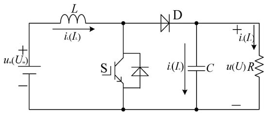
Figure 1.
The structure of a boost converter.
3. Stability Analysis of the Boost Converter Using the Proposed OCC with Composite Functions and Embedded
According to [21], a composite function can be embedded in the conventional OCC to change the eigenvalue locations of the system. Figure 2 shows the structure of the proposed OCC with a composite function embedded. With the embedding of a composite function, the control equation of the proposed OCC is written as follows:
where . This is a dimensionless coefficient that is positive and increases from zero. When this function is embedded, the system can converge on the same equilibrium point as the conventional OCC, as long as is a positive and strictly increasing function. Therefore, can be the sqrt function [21], the logarithmic function, the arc-tangent function, etc.
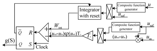
Figure 2.
The structure of the boost converter using the proposed OCC with a composite function embedded.
3.1. Embedding the Logarithmic Function
Here, is chosen as . This function is positive and increases from zero. Then, (2) is rewritten as (3):
The average model of (3) is obtained as follows:
And the duty cycle D is derived as follows:
Replacing s in (1) with D derived in (5), the average state-space model of the boost converter using OCC with embedded is derived as follows:
Setting and in (6) to zero, the equilibrium point can be obtained as follows:
Then, the Jacobian matrix evaluated at this equilibrium point is obtained as follows:
Substituting (7) into the Jacobian matrix (8) gives
According to det [λI − J] = 0 and the second-order Padé approximation, the characteristic quasi-polynomial equation can be written as follows:
where , , and .
From (10), it is obvious that . Since in a boost converter, always holds, and since , is obtained, then is established. Therefore, if is obtained, the stability condition of the OCC with embedded can be obtained.
To obtain the condition of , let f1() = and f2() = . The values of f1 and f2 were plotted against changes for comparison, and the results are shown in Figure 3. As illustrated, both f1() and f2() exhibit monotonically increasing behavior, intersecting at = 21, which is their sole intersection point. This means that when < 21, f1() < f2(); otherwise, f1() > f2().
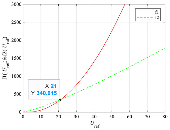
Figure 3.
Diagram of bifurcation points of the boost converter using the proposed OCC with composite function embedded.
According to the figure and analysis, with the parameters in Table 1, if is satisfied, which is more than 4, then is obtained. Compared with the conventional OCC (2) and the OCC with embedded (3), it can be seen that embedding extends the stable parameter domain further.

Table 1.
The circuit parameters of the boost converter.
3.2. Embedding the Arc-Tangent Function
Here, φ(u) is chosen as . Then, (2) is rewritten as (11):
Then, the average model of (11) is obtained as follows:
D is derived as follows:
Replacing s in (1) with D derived in (13), the average state-space model of the boost converter using OCC with embedded is derived as follows:
Setting and in (14) as zero, the equilibrium point can be obtained as follows:
Then, the Jacobian matrix evaluated at this equilibrium point is obtained as follows:
Substituting (15) into the Jacobian matrix (16) gives
According to det [λI − J] = 0 and the second-order Padé approximation, the characteristic quasi-polynomial equation can be written as follows:
where .
From (18), it is obvious that . Since in a boost converter, always holds, and when > 0, > 0 can be obtained, then is established. Therefore, if is obtained, the stability condition of OCC with the arc-tangent function embedded can be obtained. Again, the graph method was used to determine the condition .
From , it can be seen that as long as is smaller than (5), will be guaranteed. Let and . The values of f1 and f2 were plotted against changes for comparison, and the results are shown in Figure 4. As illustrated, both f1() and f2() exhibited monotonically increasing behavior, with no intersecting points. This means that, regardless of parameter changes, the stability condition of OCC with embedded is always met, demonstrating an infinite stable parameter domain.
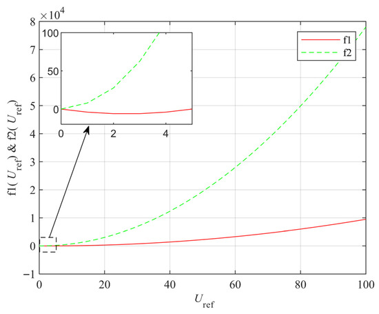
Figure 4.
Diagram of bifurcation points of the boost converter using the proposed OCC with embedded composite function .
According to the figure and analysis, with the parameters in Table 1, compared with the conventional OCC (2) and the OCC with embedded (3), it can be seen that embedding infinitely extends the stable parameter domain.
4. Calculation Verification
Taking as the variable parameter to verify the results of the above theoretical analysis, bifurcation diagrams of the proposed OCC with different composite functions embedded are shown in Figure 5. Figure 5a,b show the bifurcation diagrams of the conventional OCC and the proposed OCC with composite function embedded [21]. The results show that with embedded, the instability point is delayed from 10 V to about 15 V.
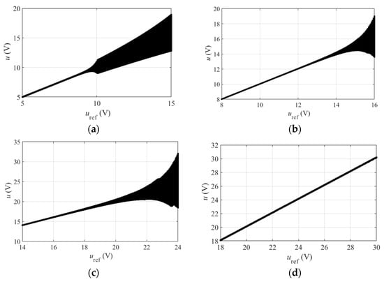
Figure 5.
The bifurcation diagram of the boost converter: (a) conventional OCC [21]; (b) proposed OCC with composite function embedded [21]; (c) proposed OCC with composite function embedded; (d) proposed OCC with composite function embedded.
Figure 5c shows the bifurcation diagram of the proposed OCC with embedded. It can be seen that as varies from 10 to 30 V, the bifurcation diagram of the proposed OCC with embedded loses its stability when increases to about 21 V. Figure 5d shows the bifurcation diagram of the proposed OCC with embedded. It can be seen that even when increases to 30 V, the boost converter using the proposed OCC with embedded remains stable throughout. The results show that compared with , with and embedded, the boost converter with an embedded composite function has a wider parameter stability domain. Moreover, the results show that is the optimal embedding function for OCC boost converters.
The calculation results indicate that different embedding functions improve the stability of the system in different ways. The comparison results are listed in Table 2, showing that embedding can achieve the optimal results, so it can be considered the optimal function.
Table 2.
Comparison results.
5. Simulation and Experimental Verification
According to the circuit parameters listed in Table 1, the stability of the boost converter was tested through simulations and experiments under varying . The simulation results are shown in Figure 6 and Figure 7. Figure 8 displays the experimental setup, and the experimental results are shown in Figure 9 and Figure 10.
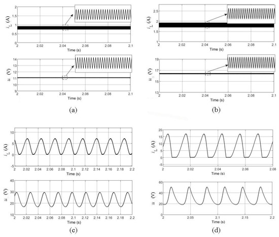
Figure 6.
Simulation results of the proposed OCC with embedded. (a) uref = 11 V; (b) uref = 16 V; (c) uref = 22 V; (d) uref = 28 V.
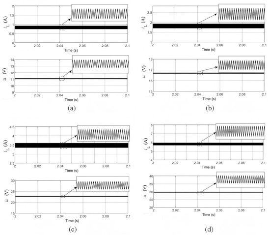
Figure 7.
Simulation results of the OCC with composite function embedded. (a) uref = 11 V; (b) uref = 16 V; (c) uref = 22 V; (d) uref = 28 V.
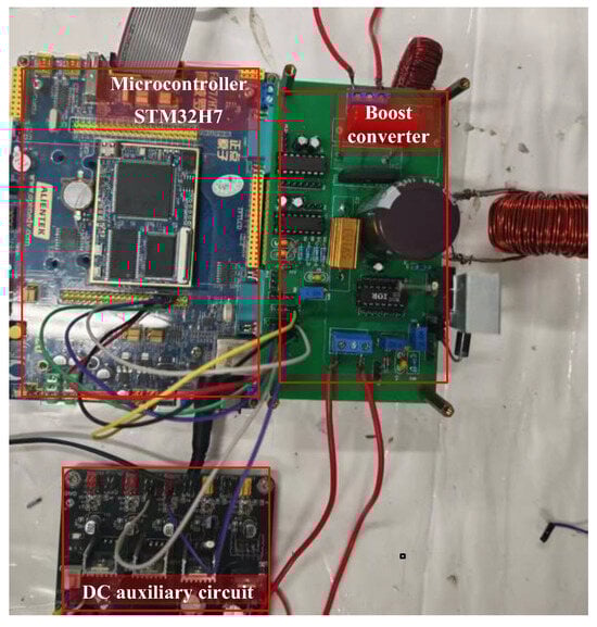
Figure 8.
Experimental setup.
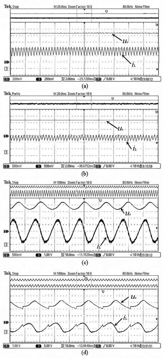
Figure 9.
Experimental results of the proposed OCC with composite function embedded (Channel 1 is the value of ; Channel 3 is the value of ). (a) uref = 11 V; (b) uref = 16 V; (c) uref = 22 V; (d) uref = 28 V.
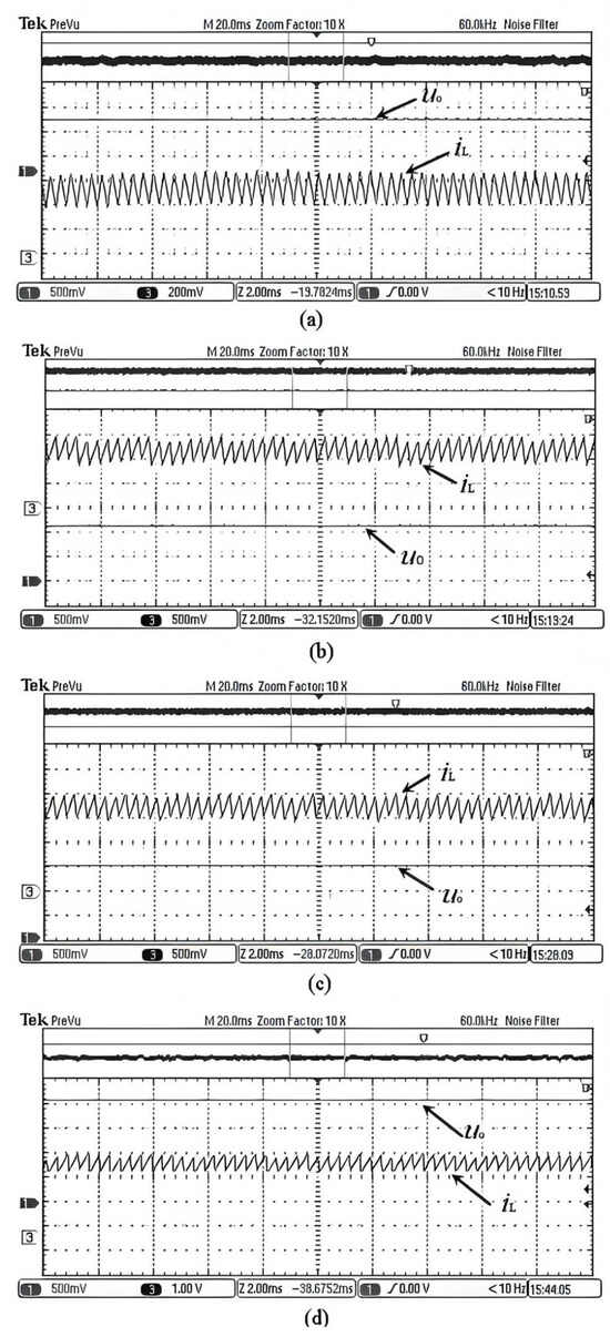
Figure 10.
Experimental results of the proposed OCC with composite function embedded. (Channel 1 is the value of ; Channel 3 is the value of ). (a) uref = 11 V; (b) uref = 16 V; (c) uref = 22 V; (d) uref = 28 V.
5.1. Simulation Results
Figure 6 displays the results of the boost converter with the proposed OCC with embedded. From the results, it can be seen that under 11 V and 16 V, the boost converter can operate stably with this control method, and no bifurcation or other nonlinear phenomena occurs. However, when increases to 22 V, bifurcation occurs (Figure 6c), which means that the system using the proposed OCC with embedded loses its stability. Figure 6d shows that when continues increasing to 28 V, the bifurcation becomes increasingly severe.
Figure 7 displays the simulation results of the boost converter using the proposed OCC with embedded. The results show that under 11 V, 16 V, 22 V, and even 28 V, the boost converter can maintain stable operation without any bifurcation or other nonlinear phenomena, as shown in Figure 7. The results show that the simulation results are consistent with the calculation results.
5.2. Experimental Results
Figure 8 shows the experimental prototype and control platform. As in [21], the MOSFET IRF640N switch and the BYW29-200 fast recovery diode were used in the experimental prototype. Control was implemented using the STM32H7 microcontroller.
In the experimental prototype, a sampling resistor Rs = 0.5 Ω was used to measure the inductor current iL. The resulting voltage us across Rs was monitored using an oscilloscope, which was then processed and sent to the controller to restore it to iL. The output voltage uₒ was regulated using a voltage divider consisting of two series resistors: R1 = 30 Ω and R2 = 370 Ω. The voltage uo1 across R1 was measured using the oscilloscope, which was then processed and sent to the controller to restore it to u. The relationships between us and iL and between uo1 and u are as follows:
Figure 9 and Figure 10 display the experimental results. The results illustrate that the experimental results are consistent with the simulation results. By using the proposed OCC with embedded composite function , the system maintains stable operation under 11 V and 16 V, and no bifurcation or other nonlinear phenomena occur. However, under = 22 V, the system loses stability, and bifurcation occurs (Figure 9c). The bifurcation becomes more severe when continues to increase, as shown in Figure 9d. As shown in Figure 10, by embedding , the boost converter can work stably under 11 V, 16 V, 22 V, and even 28 V.
Thus, the simulation and experimental results are mostly in agreement with the presented theories, demonstrating that different embedding functions can improve the stability of the system in different ways. Among them, embedding achieves optimal results, so it can be considered the optimal function.
6. Conclusions
Building upon the foundational work of [21], this study investigates selected embedding functions, specifically the logarithmic and arc-tangent functions, for enhancing the stability of one-cycle-controlled converters. Through state-space averaging and Jacobian matrix analysis, the stability boundaries and parameter domains were determined. Simulations and experiments consistently validated these theoretical findings. First, during the research process, it was found that for logarithmic functions, ln(u+1) rather than lnu should be used as the embedding function to broaden the parameter stability domain. The results further clarify that the embedding function should be a positive, monotonic function that starts at zero. The analytic results indicate that the stability region of uref is enlarged to more than when is embedded and the stability region of uref is enlarged to infinity with . This means that embedding results in no bifurcation or other nonlinear phenomena as parameters vary. Therefore, the arc-tangent function is the optimal function, providing the boost converter with an infinite stable parameter domain.
While the arc-tangent function is identified as the optimal choice, it is likely not unique. Therefore, future work will focus on generalizing the essential characteristics that define an optimal embedding function to guide the selection of other potential candidates. Furthermore, a comprehensive evaluation of the boost converter’s efficiency under different load conditions will be conducted to further validate the practical efficacy of the proposed method.
Author Contributions
Conceptualization, L.W. and L.C.; methodology, L.W.; software, J.L.; validation, L.W., J.L. and W.M.; data curation, L.C.; writing—original draft preparation, L.W.; writing—review and editing, W.M. All authors have read and agreed to the published version of the manuscript.
Funding
This research was funded by the National Natural Science Foundation of China, grant number 62001169 and Guangzhou 2025 Basic and Applied Basic Research Project, grant number SL2024A04J01736.
Data Availability Statement
The original contributions presented in this study are included in the article. Further inquiries can be directed to the corresponding author.
Conflicts of Interest
The authors declare no conflict of interest.
Abbreviations
The following abbreviations are used in this manuscript:
| OCC | One-cycle control |
| SIDO | Single-inductor dual-output |
| OGY method | A chaos control method proposed by E. Ott, C. Grelogi, and J. A. Yorke |
| OPF | Occasional proportional feedback |
| TDF | Time delay feedback |
| EBC | Energy balance control |
References
- Smedley, K.M.; Cuk, S. One-cycle control of switching converters. IEEE Trans. Power Electron. 1995, 10, 625–633. [Google Scholar] [CrossRef]
- Ma, D.; Ki, W.-H.; Tsui, C.-Y. An integrated one-cycle control buck converter with adaptive output and dual loops for output error correction. IEEE J. Solid-State Circuits 2004, 39, 140–149. [Google Scholar] [CrossRef]
- Jia, X.; Sha, D.; Zhao, Y. Unified One-Cycle Control for Fully Digitalized ZVS Four-Switch Buck–Boost Converter During Bidirectional Power Flow Transition. IEEE Trans. Power Electron. 2024, 39, 11295–11307. [Google Scholar] [CrossRef]
- Hu, W.; Zhang, B.; Yang, R.; Qiu, D.Y. Dynamic behaviours of constant on-time one-cycle controlled boost converter. IET Power Electron. 2018, 11, 160–167. [Google Scholar] [CrossRef]
- Xie, L.; Shi, J.; Yao, J.; Wan, D. Research on the Period-Doubling Bifurcation of Fractional-Order DCM Buck–Boost Converter Based on Predictor-Corrector Algorithm. Mathematics 2022, 10, 1993. [Google Scholar] [CrossRef]
- Liao, X.; Ran, M.; Yu, D.; Lin, D.; Yang, R. Chaos analysis of Buck converter with non-singular fractional derivative. Chaos Solitons Fractals 2022, 156, 11794. [Google Scholar] [CrossRef]
- Liu, W.; Zhang, H.; Zhang, X. Dynamical Analysis of Hybrid-Scale Bifurcation in One-Cycle Controlled Single-Inductor Dual-Output Buck DC–DC Converters. Int. J. Bifurc. Chaos 2018, 11, 160–167. [Google Scholar] [CrossRef]
- Ma, W.; Wang, M.-Y.; Nie, H.-L. Control of Hopf bifurcation in the one-cycle controlled boost converter and its experimental implementation. Acta Phys. Sin. 2011, 60, 100202. [Google Scholar] [CrossRef]
- Song, Y.; Li, Y.-B.; Li, C.-H. Ott-Grebogi-Yorke controller design based on feedback control. In Proceedings of the 2011 International Conference on Electrical and Control Engineering, Yichang, China, 16–18 September 2011; pp. 4846–4849. [Google Scholar]
- Liao, H.; Wang, D.; Xie, J.; Xu, Y.; Yao, C.; Tang, Z. Chaotic Dynamics and Self-Recovery Control for a Magnetic-Levitation Spacecraft Under Single-Rod Fault. IEEE Trans. Aerosp. Electron. Syst. 2025, 61, 5788–5798. [Google Scholar] [CrossRef]
- Rhea, B.K.; Harrison, R.C.; Whitney, D.A.; Werner, F.T.; Muscha, A.W.; Dean, R.N. Hardware Implementation of Chaos Control Using a Proportional Feedback Controller. In Proceedings of the 5th International Conference on Applications in Nonlinear Dynamics, Rome, Italy, 17–20 February 2019; pp. 153–163. [Google Scholar]
- Wu, R.; Zhang, X.; Jiang, W.; Zhong, S. Bifurcation analysis and chaos control in a fourth-order DC–AC H-bridge inverter. Nonlinear Dyn. 2025, 113, 9005–9031. [Google Scholar] [CrossRef]
- Lu, W.-G.; Xu, P.-Y.; Zhou, L.-W.; Luo, Q.-M. Bifurcation Control of Current-Mode Buck Converter via TDFC. Chin. Phys. Lett. 2010, 27, 030501. [Google Scholar] [CrossRef]
- Ma, Y.; Fang, L.; Zhou, X.; Wang, S. Bifurcation Control of Current-type Boost Converter. In Proceedings of the 2022 IEEE International Conference on Mechatronics and Automation (ICMA), Guilin, China, 7–10 August 2022; pp. 237–241. [Google Scholar]
- El Aroudi, A.; Haroun, R.; Cid-Pastor, A.; Martinez-Salamero, L. Suppression of line frequency instabilities in PFC AC-DC power supplies by feedback notch filtering the pre-regulator output voltage. IEEE Trans. Circuits Syst. I Regul. Pap. 2013, 60, 796–809. [Google Scholar] [CrossRef]
- Ma, W.; Zhang, R.; Wang, L.; Li, J.; Dong, Z.; Zhang, Y.; Hu, M. Stabilizing the buck converter with a first-order-filter-based time delay feedback controller. IEEE Access 2018, 6, 1967–1973. [Google Scholar] [CrossRef]
- Kavitha, A.; Uma, G. Resonant parametric perturbation method to control chaos in current mode controlled DC-DC buck-boost converter. J. Electr. Eng. Technol. 2010, 5, 171–178. [Google Scholar] [CrossRef]
- Zamani, N.; Ataei, M.; Niroomand, M. Analysis and control of chaotic behavior in boost converter by ramp compensation based on Lyapunov exponents assignment: Theoretical and experimental investigation. Chaos Solitons Fractals 2015, 81, 20–29. [Google Scholar] [CrossRef]
- Balamurugan, P.; Kavitha, A.; Sanjeevikumar, P.; Daya, J.F.; Sutikno, T. Periodic Perturbation Method for Controlling Chaos for a Positive Output DC-DC Luo Converter. Int. J. Power Electron. Drive Syst. (IJPEDS) 2017, 8, 775–784. [Google Scholar] [CrossRef]
- Lei, W.; Qinghua, W.; Wei, M.; Wenhu, T. Stability improvement for one cycle controlled boost converters based on energy balance principle. Chin. J. Electron. 2023, 32, 1293–1303. [Google Scholar] [CrossRef]
- Wang, L.; Chen, L.; Ma, W.; Li, J. One-Cycle Control with Composite Function Embedded for Boost Converters. Symmetry 2025, 17, 559. [Google Scholar] [CrossRef]
Disclaimer/Publisher’s Note: The statements, opinions and data contained in all publications are solely those of the individual author(s) and contributor(s) and not of MDPI and/or the editor(s). MDPI and/or the editor(s) disclaim responsibility for any injury to people or property resulting from any ideas, methods, instructions or products referred to in the content. |
© 2025 by the authors. Licensee MDPI, Basel, Switzerland. This article is an open access article distributed under the terms and conditions of the Creative Commons Attribution (CC BY) license (https://creativecommons.org/licenses/by/4.0/).