Article

Controlling Spiral Wave Solutions in the Barkley System Using a Proportional Feedback Control

1
Mathematics Department, College of Science, Imam Abdulrahman Bin Faisal University, Dammam 31441, Saudi Arabia
2
Basic & Applied Scientific Research Center, Imam Abdulrahman Bin Faisal University, P.O. Box 1982, Dammam 31441, Saudi Arabia
3
Department of General Courses, College of Applied Studies and Community Service, Imam Abdulrahman Bin Faisal University, Dammam 34211, Saudi Arabia
*
Author to whom correspondence should be addressed.
Symmetry 2025, 17(10), 1721; https://doi.org/10.3390/sym17101721
Submission received: 8 September 2025 / Revised: 6 October 2025 / Accepted: 9 October 2025 / Published: 13 October 2025

Abstract

An important goal in cardiology and other fields is to identify and control dynamic spiral wave patterns in reaction–diffusion partial differential equations. This research focuses on the Barkley model. The spiral wave motion is controlled and suppressed within the Euclidean group rather than through Euclidean symmetry by applying a controller equation. The eigenfunctions associated with the left eigenspace of the adjoint linear equation can be used to characterize the drift or movement of the spiral wave tip trajectory when the system is perturbed. These eigenfunctions provide details regarding how the spiral wave reacts to disruptions. Perturbations to the Barkley system are examined by applying control functions and calculating the principle eigenvalue numerically. The left eigenfunctions of the Barkley equation are determined by solving the left problem associated with the 2 D Barkley equation and a 1 D dynamical controller. In addition, the control function can be used to suppress the periodic and meandering regimes of the system. In this work, the focus is on the periodic regime.

1. Introduction

In recent decades, the controlling spiral wave tip has been examined by Schlesner et al. in the context of the FitzHugh–Nagumo model, utilizing proportional feedback control [1]. Homogeneous perturbations were specifically applied to this model, concentrating on the position of the spiral wave tip to effectively stabilize its motion around a specified point within the domain. An explicit scheme was employed for the numerical methodology. In a related study, the stabilization of the spiral wave tip’s path in the FitzHugh–Nagumo model was explored by [2], who implemented a fixed-localized control action. The control of the spiral wave solution was analyzed for both successful and unsuccessful outcomes by varying different parameters of the system. Moreover, adjoint eigenfunctions associated with dynamical spiral waves were utilized in this research, as they provide valuable insights into the local response near the trajectory of the spiral wave tip [3]. A semi-implicit scheme was used for the numerical solution of this system.
This paper focuses the Barkley model which is a reaction–diffusion system. Such systems have both a reaction term, which governs the local dynamics, and a diffusion term, which accounts for propagation. This work examines the role of the diffusion term in producing spiral wave solutions. Spiral wave patterns are frequently seen in excitable media systems when the local dynamics interact with diffusive transport [4,5].
In the natural world, spiral waves are often observed in cardiac tissue, particularly when the heart experiences beating irregularities. By investigating the dynamics of these spiral wave patterns, we can deepen our understanding of the heart’s functioning and potentially develop new methods to treat cardiac disorders [6,7]. The erratic motion of spiral waves within cardiac tissue corresponds to irregular contractions of the heart muscle. This leads to a diminished effectiveness of the heart’s pumping action. Consequently, the presence of spiral waves in cardiac tissue can play a crucial role in mortality rates [8,9,10]. Suppressing or controlling the propagation of spiral waves is a critical consideration in the treatment of heart conditions. This objective can be pursued by introducing a perturbation function into the system.
Spiral wave phenomena have also been observed in simulations of the Barkley model [11]. The modified Barkley equation is frequently used as a general model for representing excitable systems. Since cardiac cells exhibit properties analogous to nerve cells [12,13,14], the Barkley model can be leveraged to study the propagation of electrical activity in excitable cellular systems. By selecting appropriate constant parameters within a suitable domain, diverse types of spiral wave patterns can be obtained in the Barkley system. The observed spiral wave patterns encompass cases of rigid rotation and meandering, as detailed in [6]. The dynamics of spiral wave solutions have been studied extensively across various fields, including biology, physics, and chemistry [15,16].
Our research specifically investigates the management of the spiral wave tip path in the Barkley model, especially for case in which the spiral wave behavior displays periodic pattern using proportional feedback control. Additionally, since we examine perturbations in the Barkley system, we analyze the sensitivity of the spiral wave tip to these perturbations using adjoint eigenfunctions. Finally, we demonstrate numerically that the spiral wave tip can be stabilized and that it satisfies the stability condition of the eigenvalue. The spiral wave motion can be suppressed by applying a proportional feedback control, which is not affected by changes in the spatial coordinates x and y. In this work, a method is presented for stabilizing the Barkley system’s spiral wave solution using a proportional feedback control function. A numerical method leveraging the principle eigenvalue is used to confirm this approach. The left eigenfunction, which is the solution of the adjoint linear system, is observed to be localized near the tip of the spiral wave. This positioning implies that placing the control function near the tip of the spiral wave will optimize control sensitivity.
The structure of the rest of this paper is as follows. In Section 2, the previous studies were explained in the control of the spiral wave solutions using strategies of the proportional feedback control compared with our current research, especially in the Barkley system. In Section 3.1, the general formula of the Barkley system is discussed, and a numerical solution obtained using an explicit method is presented. Furthermore, the stability condition of the numerical spiral wave solutions is deduced theoretically. In Section 3.1, theoretically and numerically, the successful control of solutions involving spiral waves in the nonlinear Barkley equation is analyzed in two instances: successful local control and successful global control using the proportional feedback control. In Section 3.2, the linearization of the nonlinear Barkley system with a homogeneous perturbation component is discussed theoretically and numerically, including a perturbation term, the adjoint linear system of the Barkley model is derived. In Section 3.3, the study focuses on examining how the perturbations affect the response of the controlling spiral wave tip through the analysis of the simulation of the linearization of the adjoint system. In Section 4, the best-approximated principal eigenvalue that meets the stability condition for successful control of the spiral wave is presented.

2. Research Methodology

A notable challenge lies in controlling the dynamic tip of the spiral wave for the reaction–diffusion equation. A proposed method to manage the behavior of the numerical spiral wave solution involves using a homogeneous function known as proportional feedback control. This control technique can be applied to the reaction–diffusion equation to suppress the tip trajectory of the spiral wave solution. For instance, Schlesner et al. successfully applied this method to manage the numerical solution of the spiral wave using the FitzHugh–Nagumo equation [1]. This method has proven efficient in regulating the spiral wave tip. In 2019, proportional feedback control was also studied using the response function for the FitzHugh–Nagumo system numerically [2]. Furthermore, in 2023, Yuan et al. investigated the management of the dynamic spiral wave solution within the FitzHugh–Nagumo model [17].
This study centers on investigating the management of the spiral wave tip trajectory using proportional feedback control within the Barkley model. The reason for the transition from the FitzHugh–Nagumo system to the Barkley system is that there has not been a study in the literature that focuses on the control of the numerical spiral wave solution for the Barkley system. Therefore, it is useful to study the control strategies of the numerical spiral wave solutions in the Barkley system. By looking at papers [1,2], the proportional feedback control scheme can successfully control the spiral wave solutions of the FitzHugh–Nagumo equation. By employing this method, we can effectively manage the spiral wave solution of the Barkley model and demonstrate numerically that the principle eigenvalue meets the stability condition. Additionally, we study the responsiveness of the controlled spiral wave solution in the Barkley system by employing the response function. Finally, we convert the Barkley system into a comoving frame of the reference with a wave speed of the spiral wave simulation to numerically examine the eigenvalue, enabling us to calculate the constant angular velocity. To date, there has been no comprehensive coverage of all these investigations for the Barkley system.

3. The Model

In this section, we are interested in examining three distinct cases of the Barkley model: nonlinear system, linear system, and adjoint linear system. Each case will be described both theoretically and numerically. Additionally, our objective is to theoretically and numerically control the spiral wave solution. Furthermore, explicit methods will be employed to solve all cases.

3.1. Nonlinear System for the Barkley Model

In general, a reaction–diffusion system on a finite area is formed [6] as follows:
u t = f u + D 2 u + ϵ h .
Here, u is a vector-valued function that maps the spatial and temporal coordinates to R . Specifically, u is a function of the spatial variables x R d and the temporal variable t R . The terms u t and 2 u represent the time derivative and the diffusion operator, respectively. The diffusion operator 2 u is the sum of the second partial derivatives of u with respect to each of the d spatial variables x k such that k N . The function f represents the reaction kinetics in the system. This function, which exhibits nonlinear behavior, maps from R to R , and its properties contribute to the overall smoothness of the reaction–diffusion system. The scalar matrix D , which is an element of R × , characterizes the diffusion properties of the system. The perturbation component ϵ h can also be expressed as ϵ h u , x , t [18,19]. In this work, the diffusivity D is considered to be a homogeneous constant, which manifests as a diagonal scalar matrix with positive elements [20]. The vector x is constrained to 2D Euclidean space, and the study focuses on solutions involving spiral wave patterns.
The Barkley model is used here as the mathematical representation of the reaction–diffusion Equation (1), and it is solved numerically. The Barkley model, as described in [21], is the partial differential Equation (1) expressed in the following manner on x y plane:
u t = g ( u , v ) + 2 u ,
v t = h ( u , v ) + δ 2 v ,
where
g ( u , v ) = 1 ϵ u 1 u u v + b a ,
h ( u , v ) = k ϵ ( u v ) , a , b > 0 , ϵ 1 ,
and
u = u ( x , y , t ) , v = v ( x , y , t ) , 0 < x < L 1 , 0 < y < L 1 .
Additionally, the parameter δ is set to either 0 or 1, while the parameter k ϵ is fixed at 1. According to Barkley’s method [22], the parameter ϵ is set to either 0.02 or 0.01 . These Equations (2) and (4) are considered, specified within a region:
( x , y ) [ 0 , L 1 ] 2 , L 1 R + ,
with suitable boundary and initial conditions. The Neumann boundary condition is applied for the numerical spiral wave solutions, that is,
E ( 0 , y , t ) x = 0 , E ( L 1 , y , t ) x = 0 ,
E ( x , 0 , t ) y = 0 , E ( x , L 1 , t ) y = 0 ; E = u , v .
For this analysis, we assume δ = 0 and ϵ = 0.02 .
This section first provides a concise overview of spiral waves, as well as an explanation of how to generate spiral wave solutions for the Barkley system in 2 D space. Although no analytical spiral wave solutions have been found for the Barkley system, approximate spiral wave solutions can be obtained through numerical simulation using the method outlined by Barkley [23] to introduce initial conditions that give rise to spiral waves. In other words, the initial conditions u ( x , y , 0 ) and v ( x , y , 0 ) of the numerical spiral wave solution for the Barkley system (2) can be demonstrated as follows:
u ( x , y , 0 ) = u , y L 2 u , y < L 2 , v ( x , y , 0 ) = v , x L 2 v , x < L 2 ,
where u and v are a steady state for the system (2). Depending on the values of the parameters a and b , two types of spiral wave motion have been discussed in [5]. The behavior of the spiral wave in the Barkley system can be understood as a propagating excitation wave in the xy plane by following the trajectory of the spiral wave tip. Since the Barkley system cannot be solved analytically for spiral wave solutions, an initial condition related to the variables u and v pertaining to the homogeneous equation in two dimensions will be generated using Barkley’s approach.
The approximate solutions of the Barkley system (2) are found using an explicit scheme. Numerical solutions for spiral waves can also be obtained using implicit methods; however, this research focuses on explicit methods [24,25]. Specifically, the numerical solutions of the Barkley system described by Equation (2) are obtained using the forward Euler and central finite difference methods [26], with
u j , k m = u ( x j , y k , t m ) ,
v j , k m = v ( x j , y k , t m ) .
The solutions are obtained for spatial and temporal intervals Δ x , Δ y , and Δ t along the x, y, and t axes, respectively, with indices j , k = 0 , 1 , , n and m = 0 , 1 , , n 1 , where n and n 1 are natural numbers. Numerically, the spatial increment along the x-axis is represented by Δ x , and the spatial increment along the y-axis is represented by Δ y , as follows:
x j = j Δ x , y k = k Δ y , t m = m Δ t ,
where
Δ x = L 1 n , Δ y = L 1 n , Δ t = τ n 1 , t [ 0 , τ ] , τ R + .
Therefore, it is found that
E ( x j , y k , t m ) t = E j , k m + 1 E j , k m Δ t + O Δ t ,
2 E ( x j , y k , t m ) x 2 = E j + 1 , k m 2 E j , k m + E j 1 , k m ( Δ x ) 2 + O ( Δ x ) 2 ,
2 E ( x j , y k , t m ) y 2 = E j , k + 1 m 2 E j , k m + E j , k 1 m ( Δ y ) 2 + O ( Δ y ) 2 ,
where O Δ t , O ( Δ x ) 2 , and O ( Δ y ) 2 are truncation errors. The numerical solutions corresponding to the u and v components need to be computed at each grid point ( j , k ) .
Concerning the x-direction, this implies that it is now necessary to determine the conditions that guarantee that the approximate solutions u j , k m and v j , k m are close to the exact solutions of the system (2). To obtain good approximate solutions, Δ t and Δ x must be small. Consequently, a stability condition for the numerical method for the Barkley system in two-dimensional space must be deduced using von Neumann stability analysis [27]. The Von Neumann stability analysis is a mathematical method used to derive the stability condition of numerical schemes, particularly when solving partial differential equations through discretization methods like finite difference method [28,29]. When the Barkley system (2) in 2 D is linearized around the equilibrium point ( u , v ) , the following equations can be used:
u j , k m = β 3 ( m ) μ j ξ k ,
v j , k m = β 4 ( m ) μ j ξ k ,
where
β 3 ( m ) = θ 3 σ m ,
β 4 ( m ) = θ 4 σ m , θ 3 , θ 4 , σ R ,
and
μ = μ g 1 = e 2 π g 1 n i ,
ξ = μ g 2 = e 2 π g 2 n i , g 1 , g 2 0 , , n 1 , i = 1 .
Equations (13a) and (13b) are convergent if they satisfy
| σ | 1
and divergent if they satisfy
| σ | > 1 .
As a result, it has been shown that a necessary stability condition of the Barkley system (2) in 2 D for the space step Δ x and the time step Δ t is as follows:
Δ t ( Δ x ) 2 4 + O ( Δ x ) 4 .
Under this condition, the numerical solutions of the system (2) are stable; otherwise, they are unstable.
The investigation of dynamic spiral wave phenomena has important applications, especially in medicine and the sciences. In the former, rotating spiral wave patterns have been observed in muscle tissues of the heart, such as in cases of atrial fibrillation [30,31]. The tip trajectory within the spiral wave simulation is manipulable with the proportional feedback method [32]. The proposed technique has been demonstrated to effectively control the spiral wave around a fixed equilibrium point within a constrained domain by monitoring the trajectory of the simulated spiral wave [33]. Therefore, this method can be applied to a different system, namely, the Barkley system, to successfully suppress the spiral wave simulations. This approach involves a homogeneous control action, defined over the entire spatial domain, that is applied to the Barkley reaction–diffusion system. The focus of this research is on the evolving path of the trajectory in the spiral wave simulation in nonlinear reaction–diffusion equations, with a specific focus on the Barkley system.
As found in the research discussed above, the Barkley system, expressed by Formula (2), is described in media with excitable properties by
u t = 1 ϵ u 1 u u v + b a f ˜ t φ x , y + 2 u ,
v t = u v .
Here, a proportional feedback control function f ˜ t is formulated as follows [32,33,34]:
f ˜ t = a 1 r 0 t r t , a 1 1 ,
where the function φ ( x , y ) represents the management action. The constant a 1 is referred to as the feedback strength, and r is the span of the spiral wave tip’s trajectory x tip ( t ) , y t i p t from the desired central point ( x c , y c ) in Cartesian coordinates, which is calculated as follows:
r t = x c , y c x tip t , y tip t 2 .
The variable r 0 represents the radius of the desired circular orbit. The central point ( x c , y c ) can be positioned at any location within the bounded spatial domain. The tip of the spiral wave, denoted as ( x tip ( t ) , y tip ( t ) ) , is crucial for gaining insight into the characteristics of spiral wave motion in the Barkley model. In the Barkley system, the spiral wave consists of a leading wave face and a trailing back wave that face at the tip trajectory of the spiral wave simulation. Consequently, the isoclines of the solutions corresponding to spiral waves for the two numerical solutions u and v are significant, as they allow us to characterize the spiral wave tip ( x tip ( t ) , y tip ( t ) ) through the intersection of the two isoclines.
In this work, the focus is solely on the scenario involving a homogeneous control action function, which can be expressed as follows:
φ x , y = 1 , x , y .
The focus of this work is on the case in which the control action function φ is situated close to the intended focal point of the spiral wave. The numerical determination of the sought-after radius r 0 by solving the following ordinary differential equation, as in [32]:
d r 0 ( t ) d t = 1 a 2 r t r 0 ( t ) , a 2 τ ,
where the arbitrary variable τ denotes the time period of the fixed rotating of the tip of the spiral wave simulation. Concerning the dynamics of the controller described by Equation (22), the core radius r 0 can be approximated efficiently using the forward Euler method. When the shift in the dynamics of the spiral wave is constrained and the wave is maneuvered around the intended center of rotation in a steady manner, the function r t approaches the spiral core’s radius r 0 [13,32]. That is, the following limit holds:
lim t r ( t ) = r 0 .
In simpler terms, the value of function r t following the motion of the spiral wave’s tip is attracted towards the core’s radius r 0 . The tip trajectory of the spiral wave simulation is effectively anchored nearly the fixed point of the periodic system. The central point of the spiral core can be determined numerically using the following formula:
x c = max 0 t t 1 x tip t + min 0 t t 1 x tip t 2 ,
y c = max 0 t t 1 y tip t + min 0 t t 1 y tip t 2 , t 1 R + .
Furthermore, the desired radius r 0 of the circular orbit can be determined numerically through the 1 D controller dynamics with a given initial condition, using the following equation:
r 0 = x tip x c 2 + y tip y c 2 .
In this study, the center ( x c , y c ) of the circle is investigated for achieving effective management over the spiral wave’s location at the center of the bounded domain or close to the bounded domain. Additionally, the desired radius r 0 is assumed as an initial guess for system (22). Using one of the most commonly employed techniques, the movement of the spiral wave tip rotates about a fixed central point, as illustrated in Figure 1.
For a specific set of model parameters, ϵ = 0.02 , a = 0.5 , k ϵ = 1 , and b = 0.05 , it can be seen that the path of the spiral tip can be dominated using a particular control method that uses the functions φ x , y and f ˜ t . Regarding to model parameters a and b , there is the boundary domain of the model parameters for the Barkley system, for the behavior of the spiral wave to be understood [35]. The control parameters a 1 and a 2 are set to 0.01 and 1000, respectively. The initial approximation for the value of r 0 is 5, while the desired central position of the rotating spiral wave is at ( x c , y c ) = ( 30 , 30 ) . The isolines corresponding to the variables u and v are established at 0.15 . The image of the spiral wave tip is captured at time 2500, with a step size of Δ t = 0.1 and spatial steps of 0.33 in both the x-and y-directions. Panels ( a ) and ( b ) show the numerical solution along with the tip trajectory ( x tip , y tip ) of the Barkley system’s spiral wave, obtained using Matlab. The results indicate that the propagation of the spiral wave in the Barkley system can be effectively controlled, showcasing successful control over the movement of the wave tip within the Euclidean group, which refers to a finite plane. If the numerical solutions for the spiral wave represent equilibria, then translating, rotating, or reflecting these solutions will yield new equilibria as well. This is due to the application of Euclidean symmetry [36]. It is observed that if the desired central point ( x c , y c ) , where x c , y c R + , is sufficiently close to the path of the spiral wave solution’s tip, as illustrated by the filled red stationary point in Figure 1, then the movement of the spiral tip can be easily drawn toward a spiral core radii r 0 centered at the point ( 30 , 30 ) . This suggests that the proportional feedback control function f ˜ t is capable of steadying the trajectory traced by the spiral wave’s tip, guiding it toward the fixed central point and enabling stable rotation within the coordinate grid points. This scenario is referred to as local control.
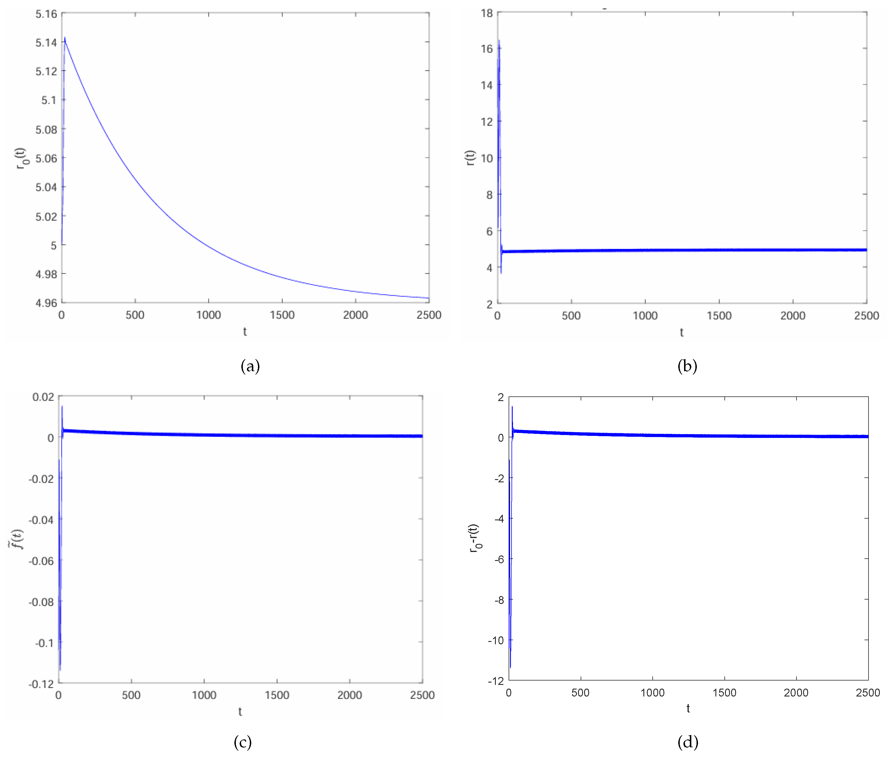
As shown in Figure 1, the path traced by the spiral wave’s tip does not exhibit unsteady rotation. The motion of the path of the spiral wave tip is consistently regulated, resulting in the fixed rotation of its trajectory. Therefore, the function f ˜ t approaches zero when the functions r 0 ( t ) and r t coincide, as depicted in Figure 2.
For the parameters ϵ = 0.02 , a = 0.5 , k ϵ = 1 , and b = 0.05 , Figure 2a shows that the control force function f ˜ t approaches zero. The initial value of r 0 is estimated to be 5, using the parameters a 1 = 0.01 and a 2 = 1000 and a central point of ( x c , y c ) = ( 30 , 30 ) . Additionally, the forward Euler method is used to numerically solve the ordinary differential Equation (22), with a time step of Δ t = 0.1 . Since the function r t matches the desired core radius r 0 , as can be seen by comparing Figure 2a,b, this fulfills Formula (23). As shown in Figure 1a, the initial transient of the spiral wave tip trajectory is not eliminated. This causes the tip to move toward the left side of the y-direction since the center circle’s Cartesian coordinates are ( 30 , 30 ) . Significantly, if the spiral wave’s tip is effectively suppressed and directed toward the desired central point, the central point ( x c , y c ) will approach the target location ( x c , y c ) . If the path traced by the end of the spiral wave does not rotate near the central core area ( x c , y c ) in a circular pattern, then the central point and the target point may be entirely distinct. Assume that the central point ( x c , y c ) is ( 45 , 45 ) . In that scenario, the motion of the spiral wave’s tip will converge to the fixed central point in the periodic regime, as depicted in Figure 3.
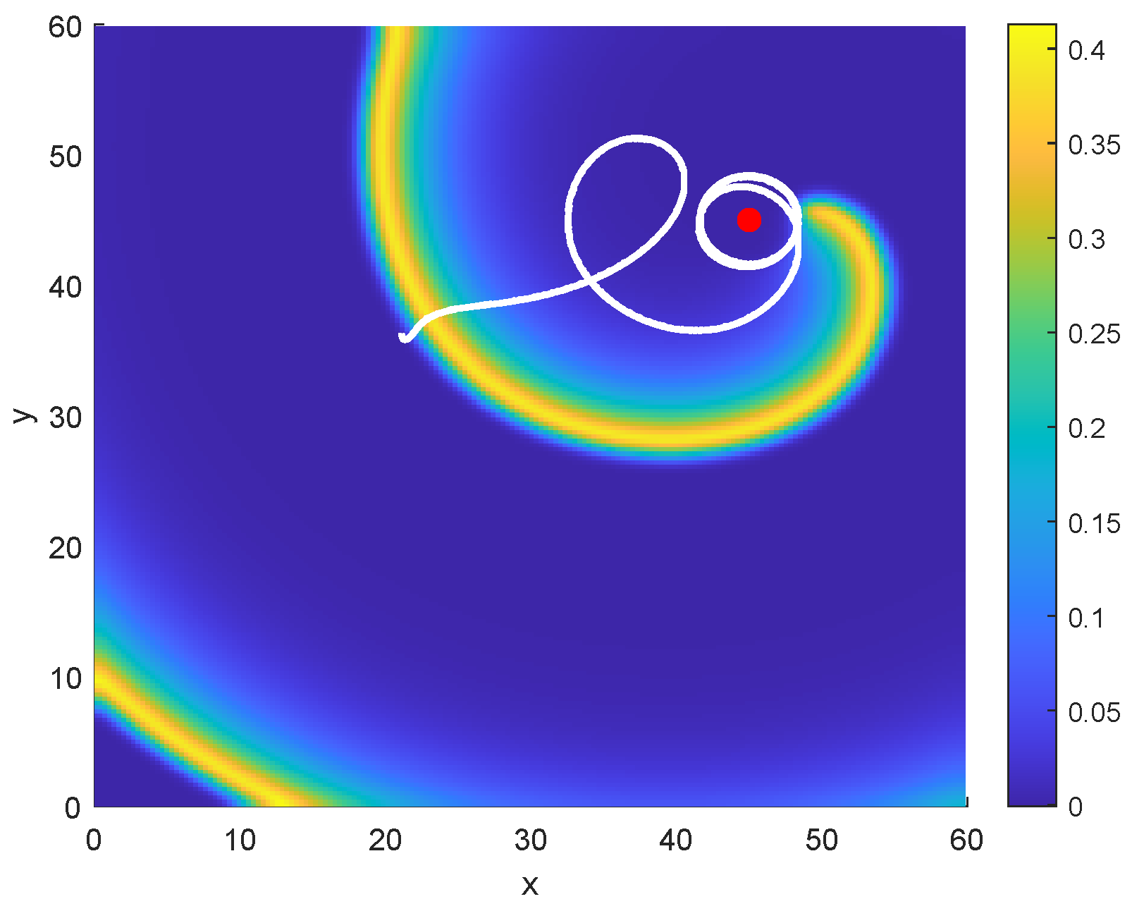
For fixed model parameters ϵ = 0.02 , a = 0.5 , k ϵ = 1 , and b = 0.05 , Figure 3 illustrates the successful control of the spiral wave as it revolves around the central core located at ( x c , y c ) = ( 45 , 45 ) , which is denoted by the red point. The final snapshot demonstrates a stable rotation of the spiral wave tip at time 2500. Initially, the variable r 0 is estimated to be 5, with control parameters a 1 = 0.01 and a 2 = 1000 . A time step Δ t = 0.1 is used for the simulation, covering the time interval [ 0 , 2500 ] , whereas the step sizes Δ x and Δ y are both set at 0.33 . The initial transient of the leading edge of the spiral wave in Figure 1 is smaller than in the spiral wave tip trajectory in Figure 3. This difference in the initial transients is because the central point ( x c , y c ) is situated far from the solution representing a spiral wave. Since the spiral wave movement is regulated as rigid rotation, this can be classified as a globally successful control scheme. Conversely, if the desired central point is located closer to the spiral wave behavior, which can be suppressed in the periodic regime, then this approach can be considered a locally successful control.
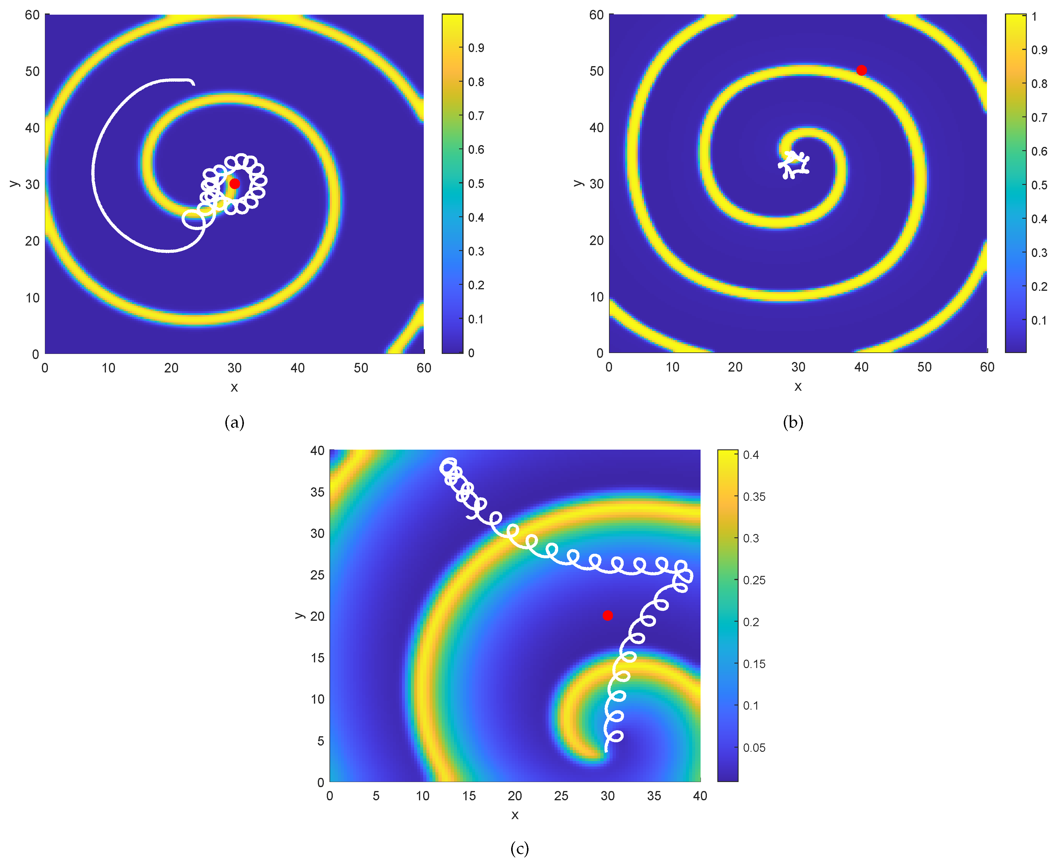
The function f ˜ t does not consistently aid in effectively stabilizing the spiral wave tip in the periodic or meandering regimes. As a result, there are three types of unsuccessful stabilizations of the spiral tip. The first scenario occurs when the spiral wave tip trajectory occasionally moves toward the central point but is unable to rotate stably around it as shown in Figure 4a.
This behavior can be suppressed, but only weakly. The second type of scenario occurs when the spiral wave tip fails to rotate around the central point at certain times as shown in snapshot Figure 4b. The third type arises when the path followed by the spiral wave tip rotates in close proximity to the boundary region as shown in of Figure 4c, which may lead to a boundary crash, the worst-case scenario. These cases occur because multiple factors have a significant influence on the management of the trajectory of the spiral tip, including the choice of values for the parameters a , ϵ , and b in the Barkley system, the initial state of the system, the choice of values for the control parameters a 1 and a 2 in the function f ˜ estimated at time t, and the positioning of the central core of the terminal point of the spiral wave. In particular, if the target point is near the initial spiral wave simulation, then controlling the movement of the spiral wave becomes more manageable. On the other hand, if the fixed target point is at a significant distance from the initial spiral wave, maintaining stable control of the spiral tip becomes difficult.
The difficulty in controlling the spiral wave is also affected by the size of the bounded area, which can impact effectively control the apex of the spiral wave. According to [37], the motion of the solution representing a spiral wave is influenced by the size of the boundaries enclosing it. As a result, the left eigenfunction of the corresponding adjoint linear system is a valuable tool for studying perturbations around the boundary area or the trajectory of the spiral tip. This is because the left eigenfunction is not greatly affected by the proximity to the boundary or the spiral wave tip. The final factors influencing control over the spiral wave’s motion are the selection of the numerical method and the size of the spatial step, which can impact the transformation of the meandering or hypermeandering spiral wave into periodic rotation. However, even with these factors considered, it remains challenging to stabilize the periodic motion of the spiral tip using the proportional feedback control function.

3.2. Linear System for Nonlinear Barkley Model

To explore the properties of the Barkley reaction–diffusion equation, the linear and adjoint linear systems need to be found. The purpose of this analysis is to determine how the Barkley system’s behavior is impacted if a small perturbation is introduced. Specifically, this perturbation will affect the spatial location of the rotation core of the spiral wave, as well as its frequency (drift), dependent on the parameters a and b . As a result, the eigenfunctions of the associated adjoint linear system provide an effective method of describing the sensitivity of the spiral waves to small perturbations. It should be noted that if the response functions (RFs) converge to zero, the spiral wave solution will be insensitive to perturbations, as reported in [38]. Therefore, in this section, the linear problem and the adjoint linear equation will be discussed, focusing on how they can be numerically solved in a Cartesian coordinate system, with white noise as the initial condition. Furthermore, formulation of the Barkley model in the comoving frame of reference will be analyzed.
The goal of linearizing the nonlinear system described by (18) is to investigate the stability of the numerical solution for the spiral wave in the nonlinear system (18). This is achieved by finding the eigenvalues of the linear system, as discussed in [19,39,40]. The following linear system is derived from the nonlinear system (18) with an independent time variable:
c t = 2 ϵ u 3 ϵ u 2 1 a ϵ v + 2 a ϵ u v b a ϵ + 2 b a ϵ u c + 1 a ϵ u + 1 a ϵ u 2 d + c x x + c y y ,
d t = c d ,
where
c = c ( x , y , t ) , d = d ( x , y , t ) , 0 < x < L 1 , 0 < y < L 1 .
The system (26) is also referred to as the right eigenfunction of the linear model. This system has a Neumann boundary condition, while the initial condition is given by white noises. Applying the central difference and forward Euler numerical methods allows a numerical simulation of the linearized system (26) to be acquired, as depicted in Figure 5, which illustrates the effective control of the numerical spiral wave using the following parameter values: ϵ = 0.02 , a = 0.5 , k ϵ = 1 , and b = 0.05 . The spiral wave is successfully controlled as it revolves around the central core located at ( x c , y c ) = ( 30 , 30 ) , which is indicated by the red point. The initial condition is set to white noises, the step size Δ t is 0.01 , and Δ x and Δ y are both 0.33 . The initial value of the variable r 0 is estimated to be 5, with control parameters a 1 = 0.01 and a 2 = 1000 . By tracking the trajectory of the spiral tip, as depicted in Figure 5, it can be observed that the spiral wave effectively revolves around the center core. However, the adjoint linear system needs to be found.

3.3. Adjoint Linear System for the Barkley Model

According to the results from Biktashev’s study [26,41] and based on the linearized system (26) of the nonlinear model (18), employing the concept of the adjoint linear operator, the (left) adjoint linear system of (26) in two dimensions can be formulated as follows:
k t = 2 ϵ u ˜ 1 3 ϵ u ˜ 1 2 1 a ϵ v ˜ 1 + 2 a ϵ u ˜ 1 v ˜ 1 b a ϵ + 2 b a ϵ u ˜ 1 k + s + k x x + k y y ,
s t = 1 a ϵ u ˜ 1 + 1 a ϵ u ˜ 1 2 k s ,
such that
k = k ( x , y , t ) , s = s ( x , y , t ) , 0 < x < L 1 , 0 < y < L 1 ,
and
u ˜ 1 = u ( x , y , τ t ) , v ˜ 1 = v ( x , y , τ t ) , t [ 0 , τ ] .
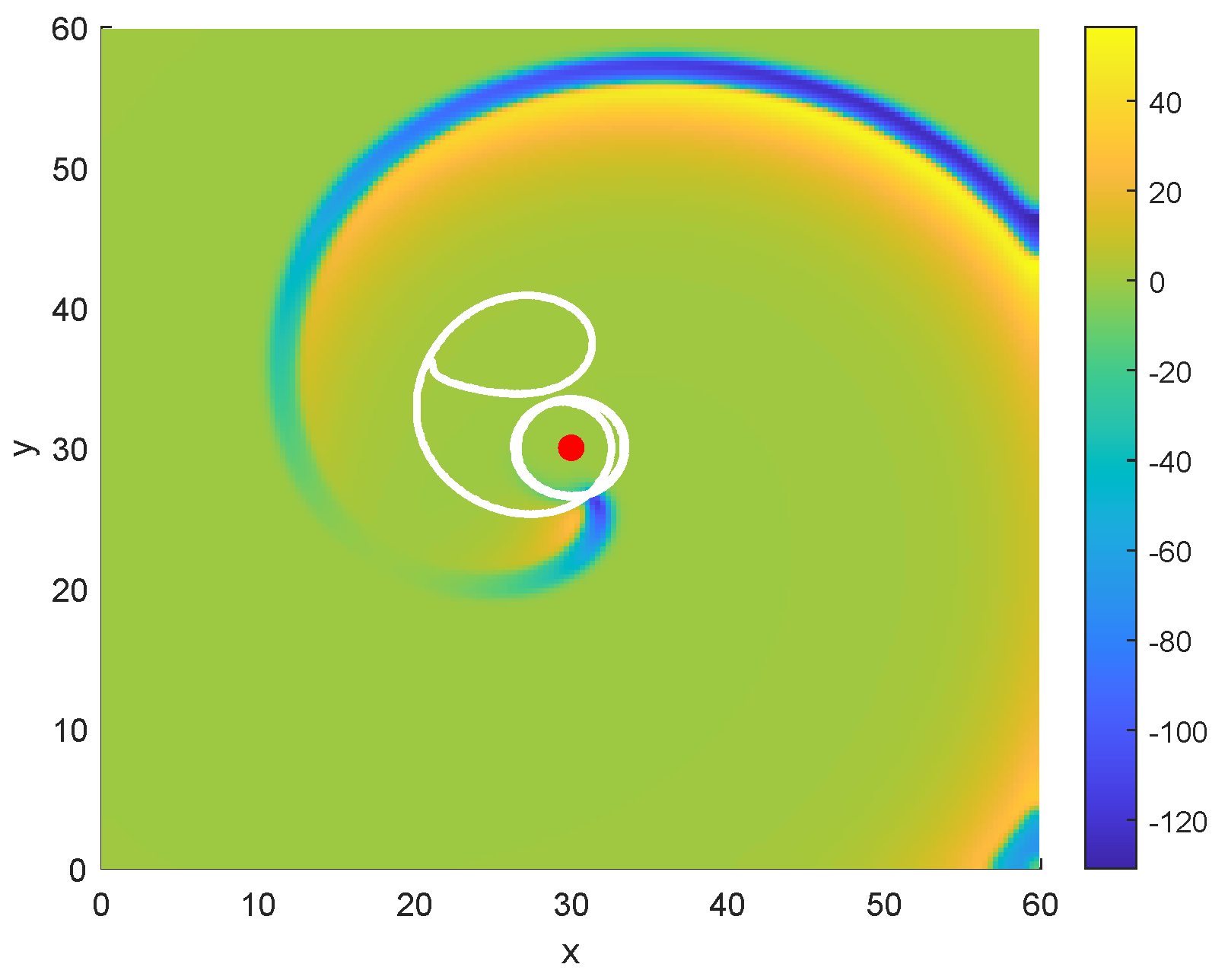
By examining Formula (30), it can be seen that the time components u and v in Equation (28) need to shift backward; otherwise, the dynamic numerical solutions for spiral waves will become unstable. The system’s boundary condition, formulated by Equation (28), is likewise Neumann, while the initial state consists of white noises. The central difference and forward Euler methods are used as the numerical methods. Consequently, the numerical simulation for the adjoint linearized Equation (28), associated with the parameters ϵ , a , k ϵ , and b , is derived and presented in Figure 6.
Figure 6 displays the spiral wave of the adjoint linear system, computed using an explicit method. The initial condition is set to white noise, and the model parameters are ϵ = 0.02 , a = 0.5 , k ϵ = 1 , and b = 0.05 . The tip trajectory of the white linear solution commences at the initiation of the black path of the spiral tip. Conversely, the dynamical spiral wave for the nonlinear and linear Barkley systems originates from the beginning of the trajectory of the white tip in the simulation of the spiral wave. Furthermore, the movement of the simulation of the spiral wave in both the nonlinear and linear systems is counterclockwise, whereas the spiral wave in the adjoint linear system moves in a clockwise direction. The central position ( x c , y c ) of the rotating spiral wave is located at ( 30 , 30 ) . The time increment chosen is Δ t = 0.1 , whereas the spatial increments in both the x- and y-directions are 0.33 . In Figure 6, it can be observed that the resulting left eigenfunction is nearly zero, except in the area around the spiral tip. Therefore, it can be understood how large the perturbation is around the spiral tip.
Overall, we have effectively controlled the solution of the spiral wave in the Barkley system with a perturbation component by employing proportional feedback control, which is a homogeneous function both numerically and theoretically. In this study, we analyze the sensitivity of the spiral wave’s tip trajectory to perturbations by utilizing the left eigenfunction from the linearization of the adjoint linear model of the Barkley equation.

4. The Stability of Spiral Wave and Numerical Results

In this part, we consider to study the stability of spiral wave patterns under proportional feedback control. Furthermore, we are providing numerical examples to confirm our results. Controlling the dynamics of spiral waves is crucial to understanding excitable media systems. Although proportional feedback control can be used to regulate the spiral wave tip trajectory, it may not always effectively control the spiral wave motion. To gain deeper insight into the movement patterns of the spiral wave tip, it is necessary to combine the perturbed Barkley system with the controller dynamics. This involves studying the eigenvalues of the perturbed system with the controller. If the eigenvalues satisfy the stability condition, it is possible to successfully control the spiral wave tip. The perturbed Barkley model (18) was previously only considered for a fixed function φ x , y = 1 . The combination of the Barkley model (18) with the 1D controller system given by (22) can be investigated to understand the regulation of spiral wave tip displacement. Computing the adjoint eigenfunction for the left linear system can also provide valuable insights into the perturbations around the spiral wave tip. The eigenvalues can yield information about the effectiveness of controlling the spiral wave tip based on specific model and control parameters.
Therefore, it is necessary to linearize the Barkley model with the controller equation and solve the resulting linear system numerically. This allows for the investigation of the Barkley model combined with a 1 D controller equation, which can be formulated as follows:
u 1 t = f 1 u 1 + D 1 2 u 1 + h t ,
where
u 1 u 1 x , y , t = u x , y , t v x , y , t r 0 t , D 1 = 1 0 0 0 0 0 0 0 0 ,
and
f 1 u 1 = g 1 u 1 h 1 u 1 f 1 u 1 = 1 ϵ u 2 1 ϵ u 3 1 a ϵ u v + 1 a ϵ u 2 v b a ϵ u + b a ϵ u 2 a 1 r 0 u v 1 a 2 r 0 ,
h t = g t h t f t = a 1 r 0 1 a 2 r .
The system (31) is now transformed to a rotating reference frame with an angular velocity c 1 , allowing the spiral wave solution to traverse the path of the spiral tip. The advantage of this approach is that the general equations of motion for the spiral wave tip trajectory can be transformed from the original reference frame to a comoving frame. As a result, the rigidly rotating spiral wave solution of the system (31) evolves into a stationary solution in the new reference frame. The difficulty in this method is that the speed c 1 of the simulation of the spiral wave must be numerically calculated.
To address this, the reaction–diffusion system with perturbation term (31) is rewritten in an unbounded plane using polar coordinates R , θ instead of Cartesian coordinates x , y . This transformation is made with equation [3]
u 1 ( x , y , t ) = u ˘ ( R , θ , t ) = u ˘ R , θ , t v ˘ R , θ , t r ˘ 0 t ,
such that
x ( R , θ ) = R cos ( θ ) , y ( R , θ ) = R sin ( θ ) .
The angle of rotation for the spiral wave is represented by θ . Furthermore, the quantity u ˘ ( R , θ , t ) is realized within the frame of reference. The chain rule is then applied to (34) and the system (31) is transformed into polar coordinates, resulting in the form
u ˘ t = f 1 u ˘ + D 1 2 u ˘ + h t ,
where
2 = 2 R 2 + 1 R 2 2 θ 2 + 1 R R .
The system (36) can now be more easily reformulated in a corotating reference frame with angular velocity c 1 . To this end, it is assumed that
u ˘ ( R , θ , t ) = z ˘ ( R , Θ ) = χ ˘ R , Θ ζ ˘ R , Θ r ˘ 0 t ,
such that
Θ = θ c 1 t Θ θ , t = θ c 1 t
and Θ is the polar angle in a rigidly rotating reference frame characterized by a spiral wave angular velocity of c 1 . In this procedure, it is assumed that the spiral wave undergoes rotation around the origin. The arbitrary quantities R and Θ represent the polar coordinate system in the original comoving frame of the reference, which does not rotate. By applying the chain rule, the system (36) can be expressed in the following manner:
u ^ t = D 1 2 u ^ + f 1 ( u ^ ) + c 1 u ^ Θ ,
where
2 u ^ = 2 u ^ R 2 + 1 R 2 2 u ^ Θ 2 + 1 R u ^ R
and
u ^ ( R , Θ , t ) = u ˘ ( R , θ , t ) .
One can observe that the numerical simulation of the system (40) is nonstationary in order that the time t is not fixed. It would therefore be useful to seek a stationary simulation of the system (40), in which the time t is an invariant, as this would allow the determination of the rotational speed c 1 of the spiral wave. This, in turn, would imply that the dynamical system can be investigated by numerically estimating the eigenvalue. A definition of Formula (38) can be provided for the variable u ˘ . The implication is that the system (40) undergoes the following transformation:
F z ˘ = f 1 z ˘ + D 1 z ˘ R R + 1 R 2 z ˘ Θ Θ + 1 R z ˘ R + c z ˘ θ .
This is used to transform the simulation of a rotating spiral wave, which is described by the fundamental Equation (31), into an equilibrium state. Linearizing the reaction–diffusion system (36) in the vicinity of the stationary solution z ˘ ( R , Θ ) with respect to the component z ˘ is proven to be beneficial. This linearization process is carried out while keeping the independent time t fixed in the comoving frame of reference, as specified by the following equation:
u ˘ ( R , Θ , t ) = z ˘ ( R , Θ ) + v ˘ ( R , Θ , t ) ,
such that
v ˘ ( R , Θ , t ) = a ˘ R , Θ , t b ˘ R , Θ , t r ˘ 1 t .
The result is that v ˘ is the perturbed linear solution. By using a Taylor expansion with respect to the function f 1 in (36), it can be shown that
f 1 ( z ˘ + v ˘ ) = f 1 ( z ˘ ) + F 1 ( z ˘ ) v ˘ + O v ˘ 2 ,
where
F 1 ( z ˘ ) = f 1 ( u ˘ ) u ˘ u ˘ = z ˘ .
is the Jacobian matrix of the reaction function f 1 . In correspondence with (44), by applying the chain rule, Equation (36) can be rewritten as follows:
G z ˘ = D 1 2 z ˘ Θ 2 + 1 R 2 2 z ˘ Θ 2 + 1 R z ˘ Θ + c 1 z ˘ Θ + f 1 ( z ˘ ) = 0 ,
v ˘ t = L ˘ v ˘ .
Consequently, the time-independent linear operator can be formulated as
L ˘ : = D 1 2 R 2 + D 1 1 R 2 2 Θ 2 + D 1 1 R R + c 1 Θ + F 1 ( z ˘ ) .
It can be observed that the system (48b) is a linear nonhomogeneous equation. Using the stable spiral wave solutions illustrated in Figure 1a, it will be numerically demonstrated that the principle eigenvalue is on the unit circle through the use of the power iteration method [42], employing the linear system (48b). The power iteration method estimates the closest principal eigenvalue for a given diagonalizable matrix A C n × n , where n N . It can be implemented more easily than other techniques, like the Arnoldi iteration method. Consequently, it is necessary to determine the rotational velocity of the spiral wave solution through numerical methods. The angular velocity c 1 is associated with the dynamics of the Barkley system and the 1 D controller. As stated previously, it is advantageous to examine the dynamical stability of the controlling spiral wave solutions by numerically calculating their eigenvalues. The angular velocity c 1 is related to the system defined in Equation (40). The angular velocity can be numerically calculated by applying Newton’s iteration method and using a stationary rotating spiral wave solution of Equation (48a), that is,
x m + 1 = x m G x m 1 G x m .
The discretization is performed on a regular grid in which the radial coordinate R ranges from 0 to 30 and the angular coordinate Θ from 0 to 2 π , using fixed spatial steps Δ R and Δ Θ .
Table 1 demonstrates how the pinning condition from [43] and Newton’s scheme can be used to estimate the approximate angular velocity c 1 for each iteration m.
It presents the numerical values of the rotational speed c 1 in the spiral wave simulation derived using Newton’s scheme. The parameters for the Barkley system are set as follows: ϵ = 0.02 , a = 0.5 , k ϵ = 1 , and b = 0.05 , while the control parameters are set to a 1 = 0.01 and a 2 = 1000 . The initial estimation for the angular velocity c 1 is 0.0110 , and the initial guess for r 0 is 5, with the center of the rotating spiral wave located at ( x c , y c ) = ( 30 , 30 ) . Additionally, the spiral wave simulations for the components χ ˘ and ζ ˘ in the stational rotational spiral wave of Equation (48a) is performed using a bilinear interpolation function. The radial step size Δ R is 0.1769 , with N R = 170 grid points, and the angular step size Δ Θ is 0.0576 , with N Θ = 110 grid points, covering the full circle up to 2 π . The step size Δ t is 0.01 , the spatial step Δ x is 0.33 , and the spatial scale is 60, with the final simulation time being 50. The motivation for using this method is that a certain number of iterations are needed to derive an estimate for c 1 . It is known that this estimation serves as a reliable approximate value if the estimate c 1 is iterated [44], so the angular velocity c 1 of the spiral wave is equal to 1.1653 . The wavelength of the spiral wave can be determined by utilizing the numerical angular velocity in conjunction with the periodic rotation of the spiral wave [45].
One can use numerical methods to calculate the eigenvalues and eigenvectors of the linear system associated with the Barkley system incorporating controller dynamics. The power iteration method, also known as the von Mises iteration, is a common numerical scheme used by researchers to estimate eigenvalues [46,47]. The explanations provided by Formula (48b) can be used to express the linear stability of the spiral wave solutions in the following manner:
L ˘ v ^ = γ ^ v ^ ; v ^ = v ^ ( R , Θ ) ,
where the variable L ˘ of the linear operator does not vary with the time variable t. Additionally, an examination of Equation (51) reveals that the component v ^ is stationary. This leads to the following equation:
L ˘ v ^ = 0 γ ^ v ^ = 0 .
Thus, γ ^ = 0 . If the eigenvalues of Equation (51) satisfy the condition Re ( γ ^ ) < 0 , then the solution of (48b) is stable. Conversely, when the eigenvalues satisfy Re ( γ ^ ) > 0 , the linear system (48b) is unstable. Analyzing the stability of the spiral wave solutions of the Barkley system with controller dynamics requires the numerical calculation of the eigenvalues through the linear system (48b). It can be demonstrated that the linear system described by Equation (52) always has a zero eigenvalue. For the controlling spiral wave solution of the Barkley system, as shown in Figure 1, stable eigenvalues are observed. Consequently, it is advantageous to employ the power iteration method for our computation.
Since the Barkley system with the controller equation is linearized around the equilibrium solution z ˘ in the corotating polar coordinate system, the linear Equation (48b) is used to numerically estimate the eigenvalue γ ^ . The numerical solver that determines the principle eigenvector for the linear system described by Equation (48b) can be implemented using the power iteration method, as follows:
v m + 1 = A v m = A m + 1 v 0 , m N .
In this formulation, the variable v m + 1 represents the principle eigenvector, and A is an n × n matrix, where n is a positive integer [48,49]. The principle right eigenvector v m + 1 is said to be approached if the principle eigenvalue satisfies the following formula:
γ i γ 1 < 1 , i N .
The principle eigenvalue γ m + 1 can be determined using the Rayleigh quotient iteration, as described by the following Equation (55) [44]:
γ m + 1 = A v m + 1 | v m + 1 v m + 1 | v m + 1 .
The power iteration scheme has the property that the stability of the spiral wave solutions can be determined by investigating the principle eigenvalue γ m + 1 . Furthermore, a key advantage of this method is its capacity for rapid computations. The largest eigenvalue γ m + 1 can be estimated using software such as Matlab (R2024b) and the power iteration method, as follows:
γ m + 1 = 0.999963267996578 .
For the principle eigenvector v m + 1 to converge according to the power iteration scheme, the eigenvalue γ m + 1 and the linear system (48b) must satisfy the following condition:
γ m + 1 < 1 .
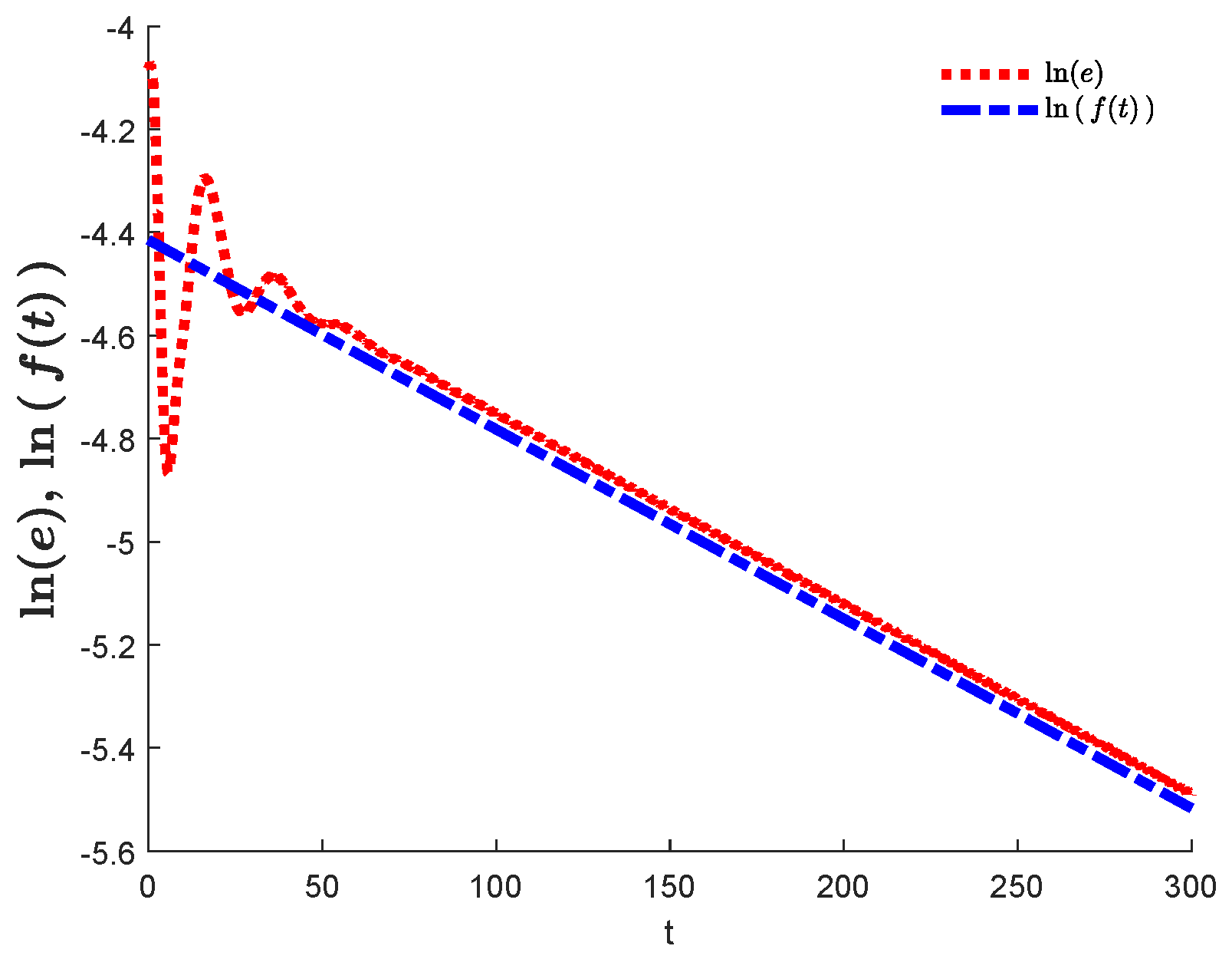
Therefore, the dynamical simulation of Equation (36) is steady. The error e between the Barkley model with the controller system (31) and the Barkley model (18) calculated using the two-norm is shown in Figure 7.
The blue curve is observed to be parallel to the red line such that γ Δ t is described as a parameter associated with the time step Δ t . The value of the parameter q 1 is 0.0121 . The space step Δ x is assigned a value of 0.1 . Additionally, the time step Δ t is set to 0.01 . However, it is indicated that the dynamic solution of system (36) is stable. As a consequence, it can be observed that the function f ( t ) tends toward zero as t increases. This behavior is demonstrated in the successful controlling spiral tip example shown in Figure 2c.

5. Conclusions

This paper explores various facets of spiral wave dynamics through an explicit method. Numerical simulations of the Barkley system are performed in Matlab, both with and without a 1 D controller equation, to study spiral waves. The spiral wave tip is located numerically, allowing its behavior to be understood. The nondecaying numerical simulations of the linear model are obtained. From this linear system, the linearization of the adjoint problem for the Barkley model with the one-dimensional controller dynamicsis is established, enabling the adjoint eigenfunctions to be calculated numerically. The numerical speed c 1 of the simulation of the spiral wave in the comoving frame of the reference with the tip trajectory for the Barkley model, without incorporating the one-dimensional controller dynamicsis, is determined, leading to the numerical computation of the principle eigenvalue and verification that the spiral wave simulations appear to be asymptotically steady. Using the Barkley model and a proportional feedback control function, it is possible to maintain the steady rotation of the spiral wave. Furthermore, by employing the adjoint eigenfunctions from the linearization of the adjoint system to the Barkley equation, along with the one-dimensional controller dynamicsis, it is possible to investigate how sensitive the simulation of the spiral tip is to perturbations of the Barkley system, as shown in Figure 6. It would be compelling to examine a more authentic, physics-driven system like the Hodgkin–Huxley equations [50]. The impetus for exploring this complex system is that it can provide insights that are more pertinent particularly to comprehending heart arrhythmias.

Author Contributions

S.M.A. contributed to the methodology, software development, formal analysis, visualization, investigation, and initial draft writing. H.Y.A. was responsible for the conceptualization, reviewing and editing the writing, and validation. All authors have read and agreed to the published version of the manuscript.

Funding

This research received no external funding.

Data Availability Statement

The original contributions presented in this study are included in the article. Further inquiries can be directed to the corresponding author.

Acknowledgments

The authors wish to thank the anonymous referees and editor for their useful comments.

Conflicts of Interest

The authors declare that there are no conflicts of interest related to the submission of this manuscript. The research is original, has not been published before, and is not currently being considered for publication, either in whole or in part, elsewhere.

References

  1. Bishop, R.C. An Introduction to Chaotic Dynamics: Classical and Quantum; IOP Publishing: Bristol, UK, 2025. [Google Scholar]
  2. Almuaddi, S.M. Control of Spiral Waves in Reaction-Diffusion Systems Using Response Function; University of Exeter (United Kingdom): Exeter, UK, 2019. [Google Scholar]
  3. Tyree, T.J.; Reiss, M.; Rappel, W.-J. Particle model of creation and annihilation captures termination dynamics of spiral defect chaos. Chaos Interdiscip. J. Nonlinear Sci. 2025, 35, 9. [Google Scholar]
  4. Taher, P.M.; Farhad, T.; Behrouz, D.; Hamzeh, S.S.; Sadat, R.F.; Ebrahim, P. A comparison of Barkley’s behavioral inhibition model (1997) with Barkley’s updated executive functioning model in predicting adult ADHD symptoms: A preliminary report using structural equation modeling. Appl. Neuropsychol. Adult 2025, 32, 140–152. [Google Scholar]
  5. Tarpan, M.; Achal, J.; Pushpita, G. Programmable Spiral Wave Dynamics: Instability Cascades Driven by Temporal Modulation in a Reaction-Diffusion System. J. Chem. Theory Comput. 2025. [CrossRef]
  6. Parvej, K.; Sumana, D. Controlling spiral wave dynamics of the BZ system in a modified Oregonator model: From suppression to turbulence. Chaos Interdiscip. J. Nonlinear Sci. 2025, 35, 1. [Google Scholar]
  7. Zou, Y.; Shi, W.; Lu, C.; Hu, B.; Qiu, F.; Liu, Y. An improved design of high-signal-to-noise ratio spiral-coil EMAT for high-temperature defect detection. Nondestruct. Test. Eval. 2025, 40, 2982–3003. [Google Scholar]
  8. Meletti, G.; Abide, S.; Viazzo, S.; Curbelo, J.; Harlander, U. Wave-like Spiral Interactions and the Emergence of Quasi-Biennial Oscillations in Strato-Rotational Flows. arXiv 2025, arXiv:2509.06691. [Google Scholar]
  9. De Coster, T.; Nobacht, A.; Oostendorp, T.; de Vries, A.A.; Coronel, R.; Pijnappels, D.A. Monitoring and modulating cardiac bioelectricity: From Einthoven to End-user. Europace 2025, 27, euae300. [Google Scholar]
  10. Ferreira, M.; Geraldes, V.; Felix, A.C.; Oliveira, M.; Laranjo, S.; Rocha, I. Advancing Atrial Fibrillation Research: The Role of Animal Models, Emerging Technologies and Translational Challenges. Biomedicines 2025, 13, 307. [Google Scholar] [CrossRef]
  11. Wang, J.; Liu, H.; Zou, Q.; Hu, J. Experimental Study on Spatiotemporal Evolution Mechanisms of Roll Waves and Their Impact on Particle Separation Behavior in Spiral Concentrators. Separations 2025, 12, 245. [Google Scholar] [CrossRef]
  12. Perov, G.A.; Kasatkin, A.D.; Presnyakov, S.A.; Kravchenko, N.P. Investigation of Modified Designs of Helix Slowwave Structures for Millimetre and Submillimetre Ranges. In Proceedings of the 2025 Systems of Signal Synchronization, Generating and Processing in Telecommunications (SYNCHROINFO), Tyumen, Russia, 30 June–3 July 2025; pp. 1–5. [Google Scholar]
  13. Babu, V.K.; Pandit, R. Deep Neural Networks can eliminate Spiral-wave Turbulence in Cardiac Tissue Models. arXiv 2025, arXiv:2509.09806. [Google Scholar] [CrossRef]
  14. Blackburne, G.; McAlpine, R.G.; Fabus, M.; Liardi, A.; Kamboj, S.K.; Mediano, P.A.M.; Skipper, J.I. Complex slow waves in the human brain under 5-MeO-DMT. Cell Rep. 2025, 44, 8. [Google Scholar] [CrossRef]
  15. de Groot, N.M.; Kleber, A.; Narayan, S.M.; Ciaccio, E.J.; Doessel, O.; Bernus, O.; Berenfeld, O.; Callans, D.; Fedorov, V.; Hummel, J.; et al. Atrial fibrillation nomenclature, definitions, and mechanisms: Position paper from the international Working Group of the Signal Summit. Heart Rhythm. 2025, 22, 1480–1491. [Google Scholar]
  16. Anichur, R.; Dipanjali, K.; Tanoy, D.; Muaz, R.; Kanti, D.U.; Musa, M.A.S.; Ghulam, M. From AI to the Era of Explainable AI in Healthcare 5.0: Current State and Future Outlook. Expert Syst. 2025, 42, e70060. [Google Scholar] [CrossRef]
  17. Ding, Q.; Wu, Y.; Huang, W.; Hu, Y.; Xie, Y.; Jia, Y. Adaptive electric shocks control and elimination of spiral waves using dynamic learning based techniques. Nonlinear Dyn. 2025, 113, 10425–10443. [Google Scholar]
  18. Emanuele, Z.; Brambley, E.J.; Dwight, B. Deep-water closure model for surface waves on axisymmetric swirling flows. Phys. Rev. Fluids 2025, 10, 024801. [Google Scholar] [CrossRef]
  19. Shumba, K.B.; Simbarashe, N.; Kenneth, S.; Tinsley, M.R. Tunable photochemical properties of silica gel Belousov–Zhabotinsky micro-reactors: Synthesis and temperature characterization. Chaos Interdiscip. J. Nonlinear Sci. 2025, 35, 6. [Google Scholar]
  20. Yiğit, O. Novel Spiral Antenna for GNSS Applications. Microw. Opt. Technol. Lett. 2025, 67, e70192. [Google Scholar]
  21. Wang, H.; Chen, H.; Sun, K.; Zhu, W.; Yao, Z. Spatiotemporal dynamics and synchronization in a memristive Chialvo neural network. Nonlinear Dyn. 2025, 113, 10365–10377. [Google Scholar] [CrossRef]
  22. Xu, H.; Wu, W.; Pan, D. Localized transient conduction block to suppress and eliminate spiral wave doppler instability: A numerical simulation study. Chaos Solitons Fractals 2025, 193, 116140. [Google Scholar]
  23. Xu, Y.; McInnes, A.; Kao, C.H.; D’Rozario, A.; Feng, J.; Gong, P. Spatiotemporal dynamics of sleep spindles form spiral waves that predict overnight memory consolidation and age-related memory decline. Commun. Biol. 2025, 8, 1014. [Google Scholar] [CrossRef]
  24. Dipa, G.; Tanisha, C.; Sarthok, S. IMPLICIT–EXPLICIT TIME INTEGRATION METHOD FOR FRACTIONAL ADVECTION–DIFFUSION-REACTION EQUATIONS. Anziam J. 2025, 67, e2. [Google Scholar]
  25. Alfifi, H.Y.; Almuaddi, S.M. Stability Analysis and Hopf Bifurcation for the Brusselator Reaction–Diffusion System with Gene Expression Time Delay. Mathematics 2024, 12, 1170. [Google Scholar] [CrossRef]
  26. Shi, S.; Xu, H.; Ma, L.; Kang, K.; Pang, Y.; Wang, Z.; Hu, J. A high sensitivity and wide frequency band vector hydrophone using PZT-based four spiral beam structure. Measurement 2025, 242, 115840. [Google Scholar]
  27. Mulimani, M.K.; Echeverria-Alar, S.; Reiss, M.; Rappel, W.J. Prediction of excitable wave dynamics using machine learning. Chaos Solitons Fractals 2025, 192, 115990. [Google Scholar]
  28. Simon, S.; Ceyhun, Ö.; Heiko, G.; Karsten, U.; Bernd, G. Stability and Instability of Time-Domain Boundary Element Methods for the Acoustic Neumann Problem. Proc. Appl. Math. Mech. 2025. [Google Scholar]
  29. He, L.; Yang, Y.; Wei, Y. Mechanism of the zigzag and spiral bubble ascension: The alternating steering and continuous chase effects of the side reflux on the bottom surface. Int. J. Heat Fluid Flow 2025, 116, 109980. [Google Scholar] [CrossRef]
  30. Zhuang, L.; Wang, Z.; Jiang, H.; Shi, X.; Xu, W.; Huang, J. The dynamics of a memristive neuron model and the elimination of spiral waves in neural networks composed of such models. Eur. Phys. J. Spec. Top. 2025, 1–19. [Google Scholar] [CrossRef]
  31. Kumar, M.M.; Rappel, W.-J. Spiral defect chaos with intermittency increases mean termination time. Phys. Rev. E 2025, 112, 034203. [Google Scholar] [CrossRef]
  32. Russo, A.M.; Desai, M.Y.; Do, M.M.; Butler, J.; Chung, M.K.; Epstein, A.E.; Guglin, M.E.; Levy, W.C.; Piccini, J.P.; Bhave, N.M.; et al. ACC/AHA/ASE/HFSA/HRS/SCAI/SCCT/SCMR 2025 Appropriate Use Criteria for Implantable Cardioverter-Defibrillators, Cardiac Resynchronization Therapy, and Pacing. J. Am. Coll. Cardiol. 2025, 85, 1213–1285. [Google Scholar]
  33. Stefano, M. Precision cardiac electrophysiology: Toward digital twins and beyond. J. Precis. Med. Health Dis. 2025, 2, 100009. [Google Scholar]
  34. Pravdin, S.F.; Alexander, V.P. Role of myocardial ischemia components in overdrive pacing of spiral waves. Chaos Solitons Fractals 2025, 196, 116332. [Google Scholar]
  35. Christian, K.; Pascal, S. Stability of N-front and N-back solutions in the Barkley model. GAMM-Mitteilungen 2025, 48, e70001. [Google Scholar]
  36. Gao, J.; Xu, B.; Shen, C. Period-doubled spiral waves without line defects in oscillatory systems. Phys. Rev. E 2025, 112, 014203. [Google Scholar]
  37. Xue, Y.; Yuan, G.; Guo, F.; Shen, W. Dynamics of spiral wave chimeras subjected to a local feedback control. Commun. Nonlinear Sci. Numer. Simul. 2025, 148, 108859. [Google Scholar] [CrossRef]
  38. Khaothong, K.; Chanchang, V.; Osaklung, J.; Sutthiopad, M.; Kijamnajsuk, P.; Luengviriya, J.; Luengviriya, C. Effect of Electric Field on Partially Pinned Scroll Waves in Excitable Chemical Media. ACS Omega 2025, 10, 35293–35300. [Google Scholar] [CrossRef] [PubMed]
  39. Benedetti, L.; Fan, R.; Weigel, A.V.; Moore, A.S.; Houlihan, P.R.; Kittisopikul, M.; Park, G.; Petruncio, A.; Hubbard, P.M.; Pang, S.; et al. Periodic ER-plasma membrane junctions support long-range Ca2+ signal integration in dendrites. Cell 2025, 188, 484–500. [Google Scholar]
  40. Chen, D.; Wang, F.; Liu, Y.; Lyu, W.; Zhao, X.; Fang, R.; Chen, L.; Li, Y. Selective Electroreduction of CO2 to CO over Ultrawide Potential Window via Implanting Active Site with Long-Range P Regulation on Periodic Pores. Angew. Chem. 2025, 137, e202421149. [Google Scholar] [CrossRef]
  41. Alfifi, H.Y. Effects of Diffusion and Delays on the Dynamic Behavior of a Competition and Cooperation Model. Mathematics 2025, 13, 1026. [Google Scholar] [CrossRef]
  42. Kai, G. Emergence and regulation of spiral waves in a neuronal network with adaptive synaptic current. Eur. Phys. J. Spec. Top. 2025, 234, 1051–1061. [Google Scholar]
  43. Speights, J.C.; Aust, V.; Lu, Q. Spiral Density Waves in the Multiple-armed Galaxy NGC 628. Astrophys. J. 2025, 981, 115. [Google Scholar] [CrossRef]
  44. Eriksson, L.E.J.; Yang, C.-C.; Armitage, P.J. Particle fragmentation inside planet-induced spiral waves. Mon. Not. R. Astron. Soc. Lett. 2025, 537, L26–L32. [Google Scholar] [CrossRef]
  45. Kolesnikov, I.D.; Bukh, A.V.; Muni, S.S.; Ram, J.S. Impact of Lévy noise on spiral waves in a lattice of Chialvo neuron map. Chaos Solitons Fractals 2025, 190, 115759. [Google Scholar] [CrossRef]
  46. Garcia-Azpeitia, C.; Ghanem, Z.; Krawcewicz, W. Global Bifurcation of Spiral Wave Solutions to the Complex Ginzburg-Landau Equation. arXiv 2025, arXiv:2507.15098. [Google Scholar] [CrossRef]
  47. Wang, J.; Chang, Z.; Liu, T.; Chen, L. A review of linear and nonlinear vibration analysis of composite laminated structures by computational approaches: 2015–2024. Nonlinear Dyn. 2025, 113, 10839–10859. [Google Scholar] [CrossRef]
  48. Du, K.; Fan, J.-J. GP-CMRH: An inner product free iterative method for block two-by-two nonsymmetric linear systems. arXiv 2025, arXiv:2509.11272. [Google Scholar]
  49. Qiao, W.; Liu, Y.; Jiao, J.; Chen, X.; Zhang, H. Spatiotemporal Analysis and Characterization of Multilayer Buried Cracks in Rails Using Swept-Frequency Eddy-Current-Pulsed Thermal Tomography. Appl. Sci. 2025, 15, 9069. [Google Scholar] [CrossRef]
  50. Eisenberg, R.S. Current Flow in Nerves and Mitochondria: An Electro-Osmotic Approach. Biomolecules 2025, 15, 1063. [Google Scholar] [CrossRef] [PubMed]
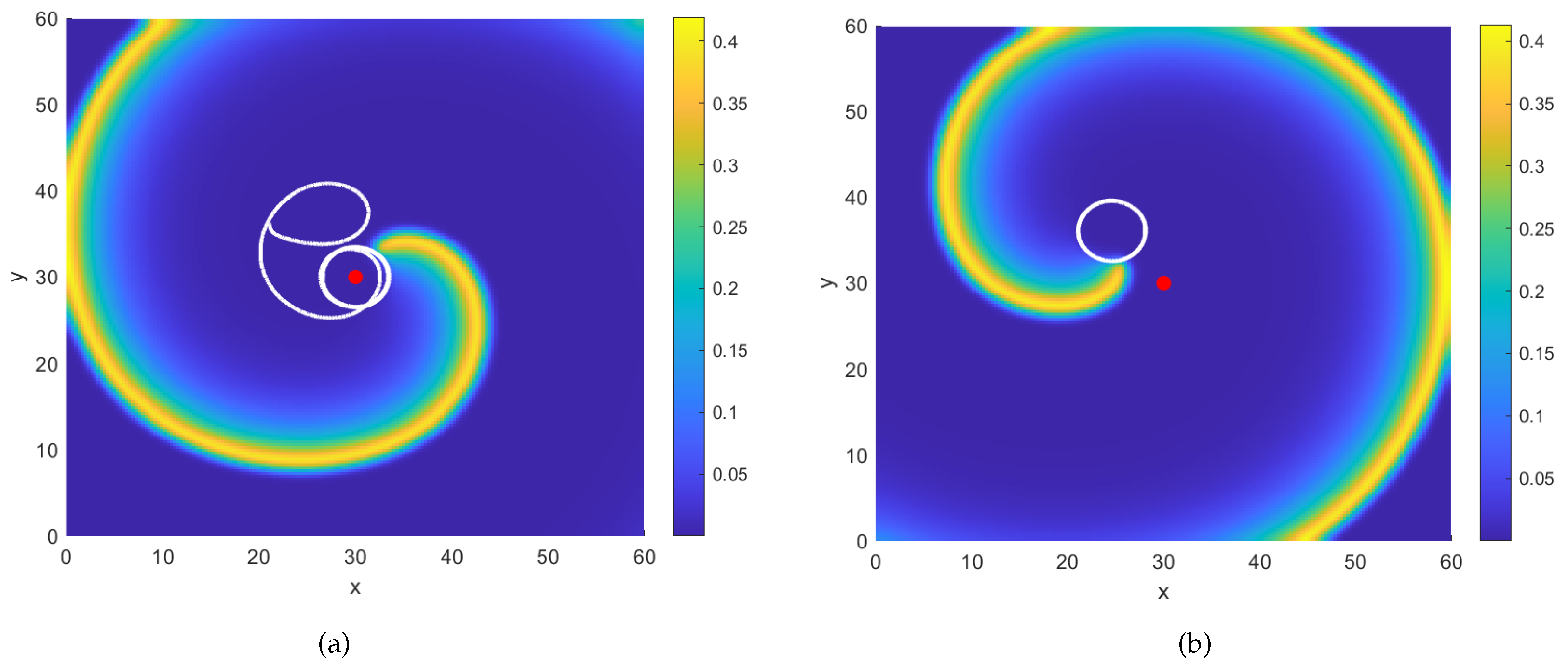
Figure 1. (a) Successful control of a spiral wave. (b) Characteristics of the spiral wave when the function f ˜ t is not applied, using the same values for the model parameters.
Symmetry 17 01721 g001
Figure 2. The functions r 0 ( t ) , r t and f ˜ t are assigned numerical values. The panel (a) shows values of the radius of the core, while the panel (b) demonstrates the distance of the tip trajectory of the spiral wave from the centre core. The panel (c) shows the value of the proportional feedback control which approaches zero, while the panel (d) explians explains difference values between r 0 and r which go to zero.
Symmetry 17 01721 g002
Figure 3. Controlled numerical spiral wave solution of the Barkley equation.
Symmetry 17 01721 g003
Figure 4. Unsuccessful control of the numerical spiral wave solution of the Barkley system for the component u. The panel (a) shows unable rotating around centre point, while the panel (b) demonstrates that tip trajectory of the spiral wave does not move around the centre core. The final panel (c) shows the movement of the spiral wave does not go to centre core and rotates around boundary region.
Symmetry 17 01721 g004
Figure 5. Approximate solution of the linear Equation (26) for the Barkley system.
Symmetry 17 01721 g005
Figure 6. Adjoint linear numerical simulation of the Barkley model, which incorporates the controller equation. The panel (a) shows the numerical solution of the adjoint linear system from beginning, while the panel (b) demonstrates the numerical solution of the adjoint linear system from end.
Symmetry 17 01721 g006
Figure 7. The red dashed line represents the approximation error e using the two-norm. The blue dash-dotted line represents the function f ( t ) = q 1 e t λ over the time period [ 0 , 300 ] . The value of λ is determined using λ = ln | γ Δ t | / Δ t = 0.0037 .
Symmetry 17 01721 g007
Table 1. Values of the estimated angular velocity c 1 m for the Barkley system.
Iteration Number mAngular Velocity Estimate c 1 m
1 c 1 1 = 0.0110
2 c 1 2 = 1.1627
3 c 1 3 = 1.1635
4 c 1 4 = 1.1644
5 c 1 5 = 1.1655
6 c 1 6 = 1.1666
7 c 1 7 = 1.1680
8 c 1 8 = 1.1696
9 c 1 9 = 1.1717
10 c 1 10 = 1.1746
11 c 1 11 = 1.1826
12 c 1 12 = 1.1812
13 c 1 13 = 1.1794
14 c 1 14 = 1.1770
15 c 1 15 = 1.1653
16 c 1 16 = 1.1653
Disclaimer/Publisher’s Note: The statements, opinions and data contained in all publications are solely those of the individual author(s) and contributor(s) and not of MDPI and/or the editor(s). MDPI and/or the editor(s) disclaim responsibility for any injury to people or property resulting from any ideas, methods, instructions or products referred to in the content.