Article

Thermo-Fluid Dynamic Performance of Self-Similar Dendritic Networks: CFD Analysis of Structural Isomers

1
Department of Mechanical Engineering, University Center Ritter dos Reis—UNIRITTER, 555 Orfanotrófio St., Porto Alegre 90840-440, RS, Brazil
2
Institute of Earth Sciences, Complex Flow Systems Lab, Rua Romao Ramalho 59, 7000-671 Évora, Portugal
3
School of Science and Technology, University of Évora, Apartado 94, 7002-554 Évora, Portugal
4
Institute of Hydraulic Research, Federal University of Rio Grande do Sul—UFRGS, 9500 Bento Gonçalves Ave., Porto Alegre 91501-970, RS, Brazil
5
Department of Mechanical Engineering, Federal University of Rio Grande do Sul—UFRGS, 425 Sarmento Leite St., Porto Alegre 90050-170, RS, Brazil
*
Author to whom correspondence should be addressed.
Symmetry 2025, 17(10), 1715; https://doi.org/10.3390/sym17101715
Submission received: 26 August 2025 / Revised: 22 September 2025 / Accepted: 1 October 2025 / Published: 13 October 2025
(This article belongs to the Special Issue Symmetry in Computational Fluid Dynamics)

Abstract

This study investigates the asymmetric effects applying heat transfer as a diagnostic tool in dendritic networks with symmetrical branching, characterized by the geometric property of self-similarity. Using a Computational Fluid Dynamics (CFD) model, we analyze five structural isomers of a three-level dichotomous branching network to evaluate the relationship between fluid dynamics, heat transfer, and geometric configuration. The main constraints are geometrical; that is, the volume at each branching level remains constant, and homothetic relationships respect the Hess–Murray law both for diameters and angles between sister tubes. The model considers an incompressible and stationary Newtonian fluid flow with Reynolds numbers ranging from 10 to 2000 and heat transfer in the range 1 to 1000 W/m2. Our results show that significant asymmetries in flow distribution and temperature profiles emerge in these symmetric structures, primarily due to the successive alignment of tubes between different branching levels. We found that the isomer with the lowest pressure drop is not the same as the one providing the most uniform flow distribution. Crucially, thermal analysis proves to be more sensitive than fluid dynamic analysis for detecting flow asymmetries, particularly at low Reynolds numbers less than 50 and q″ = 1000 W/m2. While heat transfer does not significantly alter the fluid dynamic asymmetry, its application as a diagnostic tool for identifying flow asymmetries is effective and crucial for such purposes.

1. Introduction

Tree-shaped transport networks are fundamental systems found in both natural and engineered systems, from biological circulatory systems to the cooling of microelectronic devices [1,2]. The development of complex flow systems aids in designing various engineering systems, including thermal devices, aerospace devices [3,4,5,6,7], metamaterials [8], and medical devices such as lab-on-a-chip devices [9,10].
In natural and biological systems, real structures that are branched in complex ways are usually asymmetric. This tree design also applies to artificial systems manufactured and designed for the same purpose [11,12,13,14,15,16].
In the dichotomous bifurcation of the respiratory tree, geometric asymmetry through systematic reductions in size provides better system functioning. The geometric asymmetry ensures a uniform supply to the terminal units (i.e., the acinar units) in the highest branching levels [16].
The performance of complex tree-shaped flow networks is highly dependent on the scale and geometric characteristics, such as the svelteness of the network, the ratio between diameters and lengths and, mainly, the alignment of the pipes at different bifurcation levels [11].
The proposition of structural isomers was applied in the evaluation of the asymmetric influence on the distribution of fluid flow inside symmetrical tree-shaped structures, considering the topology of the structure, increase in branching levels and the influence of the computational model [12].
The comparison between the flow of Newtonian and Non-Newtonian fluids through a complex self-similar dendritic structure demonstrated that the asymmetric effects depend on the rheological parameters as well as on the scale of the branched structure, where more svelte structures tend to obtain a better distribution symmetry. Also, the asymmetric effects are more significant for Non-Newtonian fluids compared to Newtonian fluids [13].
The design of these complex networks often aims for symmetry to achieve uniform distribution. The self-similar property in the dendritic pattern is scale-independent [11]. However, studies have shown that even in perfectly symmetric branching geometries, asymmetric flow patterns can emerge [14,15], a phenomenon attributed primarily to the fluid dynamics associated with consecutive alignments of tubes at different branching levels [14,15].
Self-similar asymmetric structures are also found in the respiratory tree of mammals such as humans, dogs, rats and rabbits, where the asymmetric nature of the branches determines the distribution of diameter ratios related to functional optimization and lung design [16].
Thus, an asymmetric division occurs and is characterized both by the distinct mass flow at each outlet and by differences in flow resistance [11,12,13]. Applying the principle of structural isomers to the design of dendritic networks with symmetrical branching, studies with Newtonian fluid flow support that asymmetric effects are primarily caused by the cascade of successive alignments [12,14,15].
In branched structures, flow asymmetry due to inertial effects is compensated by structural asymmetry, as exemplified by the geometric structure of the tracheobronchial tree, which is highly asymmetric. Thus, the shortest paths toward the periphery of the lung benefit from reduced flow resistance (i.e., ensuring correct physiological functioning), something that would not occur if the pulmonary tree were completely symmetrical [14].
Flow asymmetry evaluated only with fluid dynamics lists three important characteristics attributed to asymmetric flow in symmetric structures in the plane and out of the plane: flow inertia, path curvatures and flow division at bifurcations, which contribute substantially to flow non-uniformity [15].
While the impact of these alignments on isothermal fluid flow has been explored, the role of heat transfer in influencing or revealing these asymmetries is not well understood.
In artificial systems such as heat transfer devices applied in electronics, the challenges posed by the miniaturization of microelectronic devices remain current, such as minimizing the pressure drop in the complex channels that transport the cooling fluid and the temperature non-uniformity on the heat sink surface [17,18,19]. This offers a wide range of applications for the study of tree-shaped flow networks with heat transfer.
In the development of complex flow networks applied to heat transport, two physical laws stand out in the quest to maximize the dual objectives of low pumping energy consumption and high heat transfer load. The Hess–Murray law guides allomeric relationships to achieve the lowest pumping work [20,21,22] and the constructal law generally applies to the branching design [23,24]. The constructal law proposes that for fluid transport between point-to-area or volume and vice versa, the complex tree-shaped structure best fulfills this purpose.
The Hess–Murray law [20,21] applies only to vessels with rigid, impermeable walls and laminar flow of Newtonian fluid. In Hagen–Poiseuille flow, minimum work is achieved when the volumetric flow is proportional to the cube of the diameter in an optimized vessel. Thus, complex flow networks that follow this law require that the cube of the diameter of a parent vessel be equal to the sum of the cubes of the diameters of the daughter vessels.
The constructal law is a natural law that inherently allows for the evolution and adaptation of design over time, ensuring the system’s persistence and fulfilling its intended purpose in the best possible way [1,24]. In flow systems, the constructal law for pipe design is derived from the need to move the fluid as easily as possible, to achieve greater access to the flow through the generation of a specific design (i.e., configuration). Thus, the way to connect large and small pipes requires a ratio between the diameters of the daughter and parent vessels of 2−1/3 (i.e., Hess–Murray law) for laminar flow and 2−3/7 for turbulent flows [24].
This work advances the investigation of asymmetric effects by incorporating heat transfer into the fluid flow in symmetrical dendritic networks [11,12,13]. The use of heat transfer as a diagnostic tool for revealing geometrically induced, steady-state flow asymmetry is a novel approach that is well-supported by our methods and results.
Thermal engineering applications have ranges of interest. In this study, we applied a generic investigation range between 1 to 1000 W/m2, serving as an energy source for identifying flow asymmetries through thermal markers. However, this research can contribute to the development of applications that use similar ranges. For example, 1 to 20 W/m2 in determining the dynamic thermal properties of building materials applied to building envelopes [25,26], for 50 to 100 W/m2 in underfloor heating or cooling applications [27], for 100 to 500 W/m2 in a spiral-shaped solar collector applied to water heating [28], and for 500 to 2200 W/m2 in hydrothermal fins applied to cooling electronic devices [29].
This study aims to investigate the asymmetry effects applying heat transfer as a diagnostic tool in dendritic networks with symmetrical branching, characterized by the geometric property of self-similarity (i.e., through structural isomers), and identify the potential asymmetric effects on the flow of a Newtonian fluid limited to flows with Reynolds number 10 to 2000 and heat transfer of 1 to 1000 W/m2. Evaluate the effects of successive alignments [11,12,13,14,15] between tubes at different branching levels in a network designed according to the Hess–Murray law [20,21] are also addressed.
The determination of the average or local Nusselt number, the scale evaluation of flow networks with heat transfer, the evaluation of non-Newtonian fluids, turbulent flow and asymmetric networks are excluded from the objectives of this scientific dissemination.
This work aims to address the following questions:
(1)
Do flow asymmetries in branched structures with heat transfer differ from those without it?
(2)
Can heat transfer amplify or mitigate these asymmetric effects?
(3)
Are thermal performance markers effective for identifying fluid dynamic asymmetries?
To answer these questions, a numerical experiment study was conducted using 3D computational fluid dynamics (CFD) [30] to simulate Newtonian fluid flow through a dichotomous dendritic network of tubes with three levels of branching that has heat transfer along the tube walls.
Advancing the understanding of the effects in complex networks aids in designing various networks that transport fluids, heat, and species, both artificially (e.g., in industries) and naturally (e.g., in respiratory and circulatory systems, watershed formation with river maintenance, lava transport, etc.).

2. Methods

2.1. Geometrical Modeling

Figure 1 shows a tree-shaped flow network made of cylindrical tubes with three levels of dichotomous branching, in which all tubes are on the same plane. This figure presents the basic variables to model the system and the structures for this study.
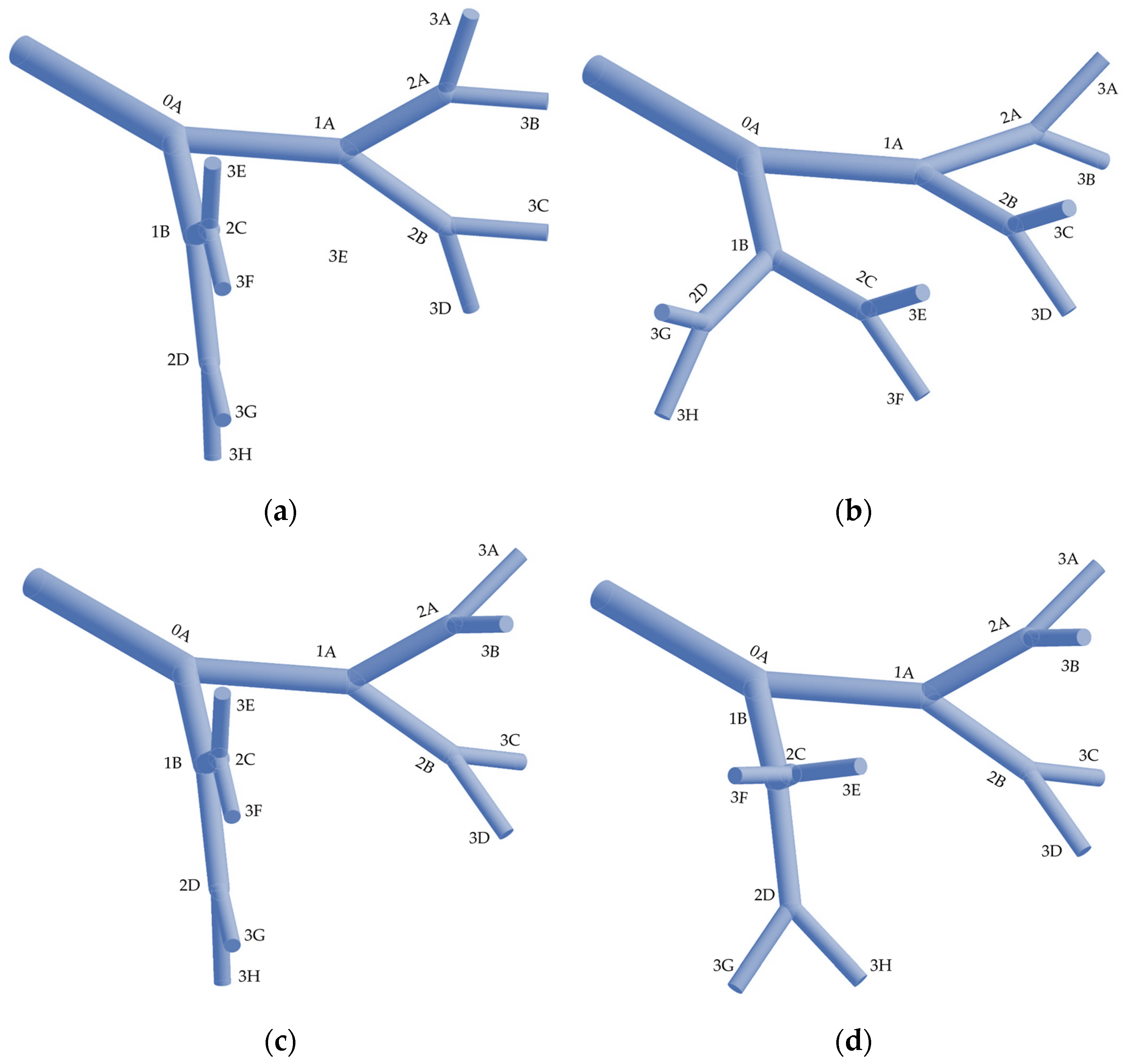
Figure 2 shows four other symmetrical geometries that are investigated. These four configurations help to test the hypothesis of successive alignments between tubes of different branching levels, in addition to the tree-shaped geometry that develops in the plane.
For all cases studied, the symmetry is not altered, since the angles between tubes of the same level, diameters and lengths remain identical in size for each flow plane. Note that to avoid successive alignments, the tubes of the upper levels have been rotated by 90 degrees with respect to the tubes of the lower levels, without any dimensional change.
The choice of the five geometries is not a simple random choice, it was designed to test the hypothesis of successive alignments that occur between the different levels of branching.
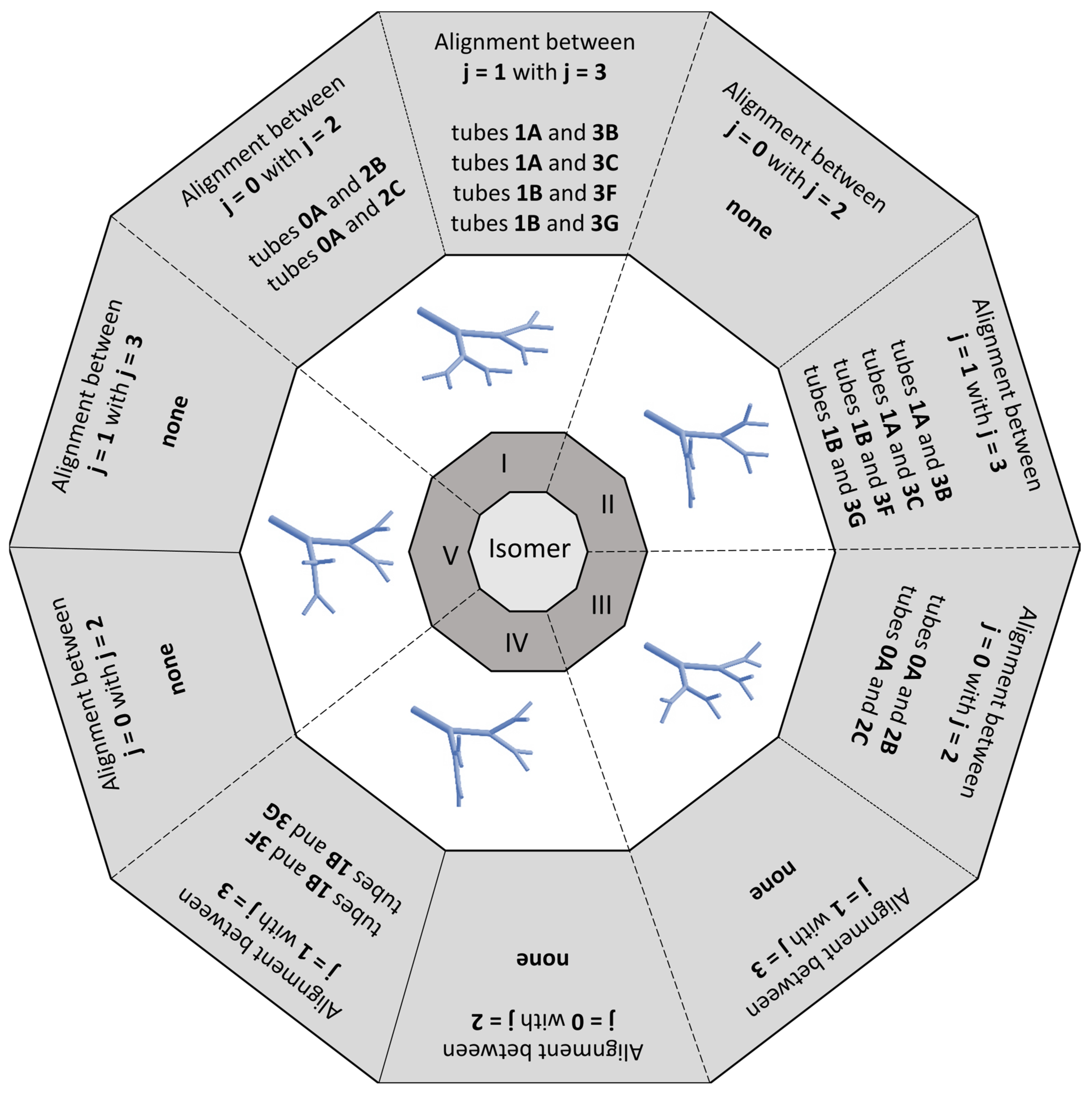
Isomer I is a commonly studied planar tree-like structure, this is the easiest to construct. [12,14,15]. Isomer III is an alternative to isomer I, since, for the restriction of equal volume between the branching levels, a geometric condition applied in the respiratory system, from diameter ratios lower than 0.7 suffers from overlaps between the tubes of the third branching level [11]. Isomer V is the most difficult to construct. This structure has been previously studied, but the effects that occur between an in-plane and out-of-plane structure still left gaps to be answered [12,15]. Thus, isomers II and IV complement a family of self-similar structures, aiming to progressively eliminate the successive alignments that occur between tubes of different branching levels [12].
Figure 3 shows criterion of alignments between tubes of different branching levels with identical dimensions different designs [12]. The five are structurally isomer networks.
The isomer IV has the singular characteristic of being structurally asymmetric about tube 0A. Note that the paths to outlets 3A, 3B, 3C, and 3D have no alignment between the tubes, and the paths to outlets 3E, 3F, 3G and 3H are aligned from level 1 to level 3, similarly to isomer II. For all other structures isomer I, II, III and V are symmetrical to tube 0A.
Understanding the fluid’s behavior when the tube network in the form of a tree loses its symmetry and becomes asymmetric in realistic designs, allows us to design fluid flow systems better. The study of isomeric structures is an important advance towards the global understanding of asymmetric effects in symmetric structures. Note that in Figure 1 and Figure 2, the plane in which the branching tubes are located differs, but the daughter tubes remain symmetrical (i.e., identical in size but with different configurations).
According to the principles of constructal design [23], it is essential to clearly establish the system’s constraints, degrees of freedom, and design objectives. One of the constraints adopted in this study is the fixed total volume of tubes at each branching level Vi = 1.767 × 10⁻⁵ m3 which remains constant throughout the analysis. Additionally, the angle between the daughter branches is maintained at 75°, a configuration known to reduce pressure losses in bifurcated laminar flow systems [22]. The ratio between the length and diameter of the tube at the initial level is also fixed at 6.77, based on observed values ranging from 6.3 to 7.0 in natural systems [2]. The system’s degree of freedom is defined by the ratio between the diameters of the daughter and parent ducts (aD). Based on these parameters, the dendritic fluidic structures [12] are constructed using Equations (1)–(4) [11].
V i = π 4 2 i D i 2 L i
V T = i = 0 3 V i = 4 V
a D = D i + 1 / D i
θ = 75 ° ,   L 0 / D 0 = 6.77
where Vi represents the volume at each branching level, θ denotes the angle between daughter branches, D and L refer to the diameter and length of the tubes, respectively, and aD defines the ratio between the diameters of parent and daughter ducts. The indices i and i + 1 correspond to the parent and daughter levels. The index i may range from 0 to 3, with lower values indicating initial branching levels, characterized by fewer tubes and outlets, and proximity to the inlet. While the volume at each level remains constant, the length ratio varies, introducing a degree of freedom into the system. Table 1 shows the values for geometric parameters used to determine the computational domain. In the Appendix A, Appendix B and Appendix C there is additional information about the dimensions of the geometry.

2.2. Mathematical and Numerical Modeling

The governing equations for mass, momentum and energy conservation are expressed in Equations (5)–(7) [31,32]. Consider a 3D laminar flow regime (ReD < 2100) through a network of tubes. Navier–Stokes equations for a steady of isothermal and incompressible Newtonian fluid are expressed in Cartesian coordinates as
· u = 0
ρ u · u = p + · τ
ρ c p u · T = k 2 T
where u is the velocity vector field, ρ is the fluid density, μ is the dynamic viscosity, p is the pressure, T is the temperature, cp is de specific heat of the fluid at constant pressure and k is the thermal conductivity.
The modeling assumptions are laminar, steady-state, three-dimensional flow of isothermal and incompressible Newtonian fluids with constant properties, no buoyancy, impermeable and no-slipping walls.
The energy and Navier–Stokes equations were solved using the Computational Fluid Dynamics (CFD) code ANSYS® FLUENT 2025-R1. The coupled solution, the pressure-based formulation applied to low-velocity incompressible fluid flows, the laminar viscosity model, and the energy model were chosen as solution parameterizations. The viscosity model is independent of the thermal model; this choice is justified because, within the operating range, the fluid dynamic and thermal properties can be considered constant.
The pressure-velocity coupling used the SIMPLEC method. The sub-relaxation parameters were 0.3 for pressure, 1.0 for density, 1.0 for forces, 0.7 for momentum, and 1 for energy. The least square cell-based method was used for the gradients, the second-order scheme was used for the pressure discretization, and the second-order upwind scheme was used for the advective term and energy term in the spatial discretization of the transport equations. The residual criteria for the continuity, momentum and energy equations were set to 10−6.
The boundary conditions for the tree flow structure are as follows: the mass flow rate is prescribed (ṁ) and temperature prescribed (Tin = 300 K) at the inlet tube; the atmosphere pressure was specified for tubes outlet (i.e., p = 0); a uniform heat transfer (q″ ≠ 0) is assumed at external walls of the tubes and the no-slip and no-penetration (i.e., impermeable wall) boundary conditions are applied on the walls within the tubes. Table 1 shows the values for boundary conditions used to parameterize the computational model.
The inlet boundary condition is justified by the possibility of specifying the mass flow rate, a desirable characteristic for studying tree-flow structures that represent natural systems. This boundary condition allows the total pressure to vary in response to the solution. The outlet boundary condition is justified to model the output based on the static pressure of the flow. The velocity values are calculated from within the domain with the gradients of the quantities fixed at zero.
The fluid chosen for this study is water (ρ = 998 kg/m3, μ = 0.001003 Pa∙s, k = 0.6 W/m∙K and cp = 4182 J/kg∙K) and tube material is the tantalum (ρ = 16,600 kg/m3, k = 57.6 W/m∙K and cp = 140 J/kg∙K). The choice of tantalum is associated with its thermal properties: it is widely used in the aerospace, nuclear, electronics, and automotive industries.
To verify the mesh, uncertainty analysis was performed considering the Grid Convergence Index (GCI) method [33,34]. The dimensionless pressure head loss (i.e., Euler number) was selected as a convergence marker in the application of the technique due to its significant relevance to fluid flow problems. Table 2 shows the grid study for a Newtonian fluid for ReD = 2000 and q″ = 1000 W/m2. Where r is the mesh ratio, ε is the relative error and de indices 1, 2, and 3 indicate the element size, and N represents the number of cells; the lower the index, the more refined the mesh and ext the value of the analysis variable according to a Richardson extrapolation.
The CGI method recommends a mesh ratio greater than 1.3 and as close as possible to r21 and r32 [33,34]. The application of the prismatic layer on the wall, necessary to capture phenomena in this region, influences a mesh ratio of ~1.9, used in this study.
In complex flow structures that apply homothetic relations, where the diameter of the tubes at the highest branching levels decreases, it is necessary to ensure a sufficient number of elements in these tubes. The number of elements in the prismatic layer near the wall increases as the element size decreases, which contributes to a mesh ratio greater than 1.3. Thus, coarse meshes exhibit significant divergence compared to finer meshes, especially for flows with higher Reynolds numbers (i.e., close to 2000, in laminar flow). This fact is explained by an insufficient number of elements in the discretization of the smaller-diameter tubes at the largest branching levels.
Finding the ideal balance between cells at the wall and at the center of the tube is not a trivial task in problems involving flow in complex networks.
For GCI method applied a fluid flow, a maximum value of 5% is considered to be acceptable [33] when the choice convergence marker reaches the asymptotic region according to a Richardson extrapolation.
The element size parameterization is equal to 0.005 m for all isomeric structures, with which we obtain a GCI of 0.24% to 0.97% for the highest Reynolds number and the highest heat transfer studied.
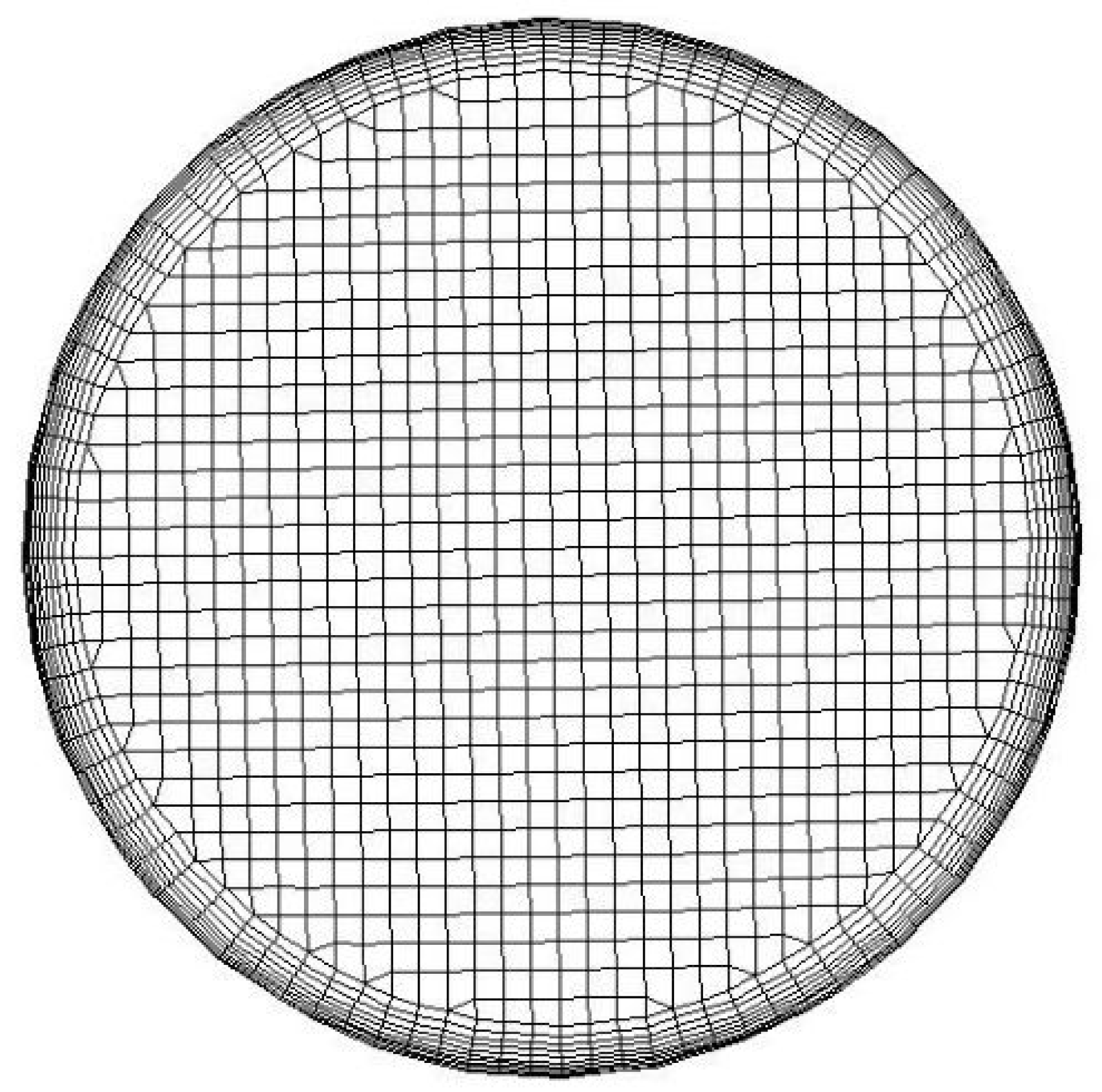
The fluid domain was discretized with hexahedral elements throughout the geometry, except in the near-wall regions, where there is a refinement of ten prismatic layers (i.e., the layers needed to create an accurate computational domain). The computational domains have a total of 1.7 × 10⁶ to 2.1 × 10⁶ hexahedral cells.
The numerical and mathematical models were validated by comparison with a similar CFD study on branched flow structures, with two levels of branching (i.e., four outputs) [35]. Without modifying the numerical model parameterization or mesh element size used in this study, a geometric adjustment with the suppression of one branching level was required for validation. Table 3 shows the parameters used for validation as well as the relative error, with their respective performance markers, 5.4% [35].
The fluid dynamic characteristics are used to compare results, there are differences in the discretization method and computational model configurations. The application of 118,000 elements with irregular tetrahedral mesh, residues 10−4, sub-relaxation parameters 0.5 for momentum and 0.8 for pressure, and SIMPLE method for pressure-velocity coupling [35]. Here, a regular mesh with 165,000 hexahedral elements, residues 10−6, sub-relaxation parameters 0.7 for momentum and 0.3 for pressure and SIMPLEC method for pressure-velocity coupling, choices that favor the stability and solution convergence.
The validity and robustness of the proposed model are verified by the same order of magnitude.

2.3. Network Thermo-Fluid Dynamic Performance

To evaluate the thermo-fluid dynamic effects and the asymmetric effects in dendritic flow networks with structural isomerism, dimensionless quantities are defined allowing the understanding and comparison of the results. The Euler number [13] is used to express the dimensionless pressure head loss according to:
E u = ρ   A t u b e 2 p / m ˙ 2
where Eu is the Euler number, Δp is the pressure drop, ṁ is the mass flow rate and Atube is the cross-sectional area of the inlet tube. In a flow where there are localized pressure losses (i.e., due to junctions, restrictions and changes in cross-section), the Euler number can be thought of as a measure of the ratio of pressure forces to inertial forces (i.e., a dimensionless measure of pressure head loss).
To investigate the asymmetry associated with fluid flow (i.e., fluid dynamic phenomena) and quantify the possible differences in the distribution of mass flow in the outlet tubes of the dendritic network the following parameter [15] is defined:
F R P = m ˙ t u b e , m / m ˙ i n
where FRP is the flow partitioning ratio, which means the fraction of the mass flow rate flowing through each tube relative to the system supply mass flow rate, ṁtube,n is the mass flow rate at the outlet of tubes in a specific branching level m, and ṁin is the mass flow rate at the inlet of the network.
The thermal effects provided by heat transfer through the walls are quantified by the dimensionless temperature according to:
T * = T m á x / T i n l e t
where T* is the dimensionless temperature, Tmáx is the maximum temperature in a given region of interest of the computational domain and Tinlet is the fluid inlet temperature parameter (i.e., 300 K).
The thermo-hydraulic performance factors [36,37,38] combining Q and R can be quantified according to:
α = Q R 1 / 3
where α are thermo-fluid dynamic efficiency, Q is heat transfer rate and R is the flow resistance, defined as R = Δp/ṁ.
The Nusselt number [32] represents the ratio of convective heat transfer to conduction heat transfer. It can be quantified according to:
N u ¯ = h   D 0 k
where N u ¯ is the overall Nusselt number, h is the heat transfer coefficient, D0 is the characteristic length and k is thermal conductivity.

3. Results and Discussion

Velocity, pressure and temperature fields were obtained by CFD numerical simulations to determine characteristics of heat transfer and fluid flow across the symmetrical dendritic network.
Our study uses the diameter ratio aD according to Hess–Murray’s law, which characterizes the optimal performance geometry or reduced flow resistance. The diameter ratio aD used here is 2−1/3. Our investigation is carried out in a flow laminar regime, the range is 10 ≤ ReD ≤ 2000. The heat transfer range is 1 ≤ q″ ≤ 1000 W/m2. The laminar viscosity model is decoupled from the thermal model, as the property is practically constant over the study interval. The computational model was validated by comparison with similar computational models. The numerical results consider residuals equal to 10−6.

Pressure Drop Characteristics

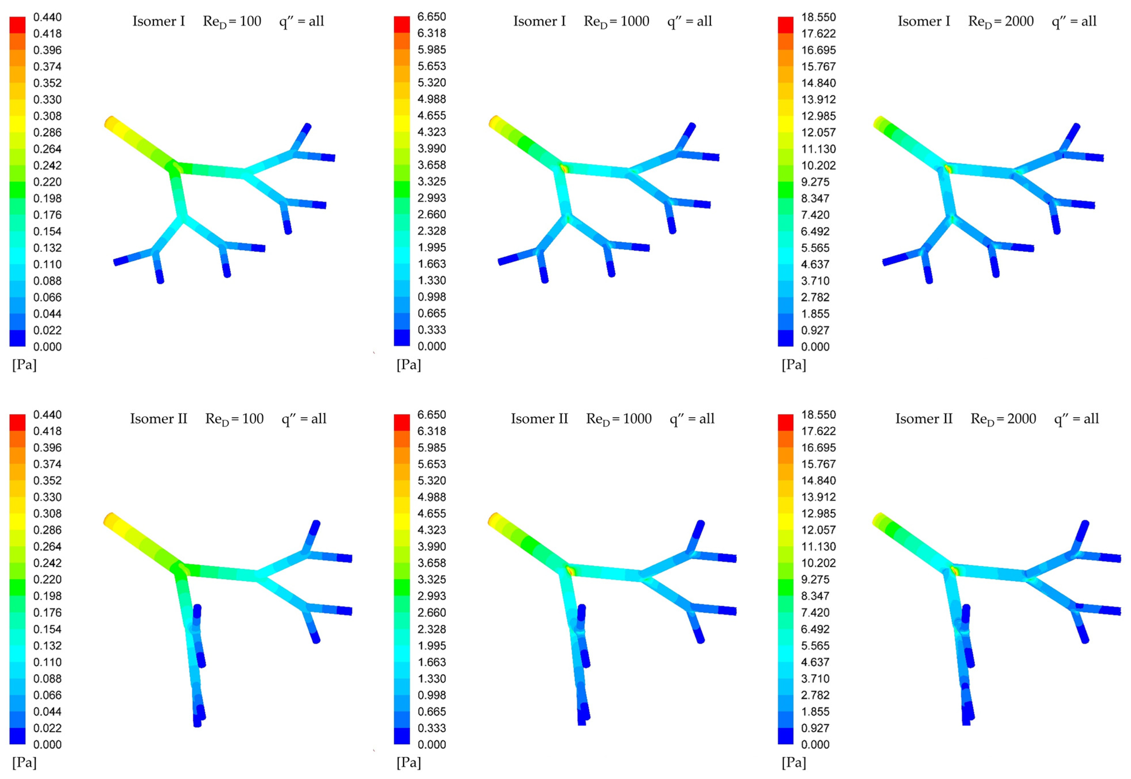
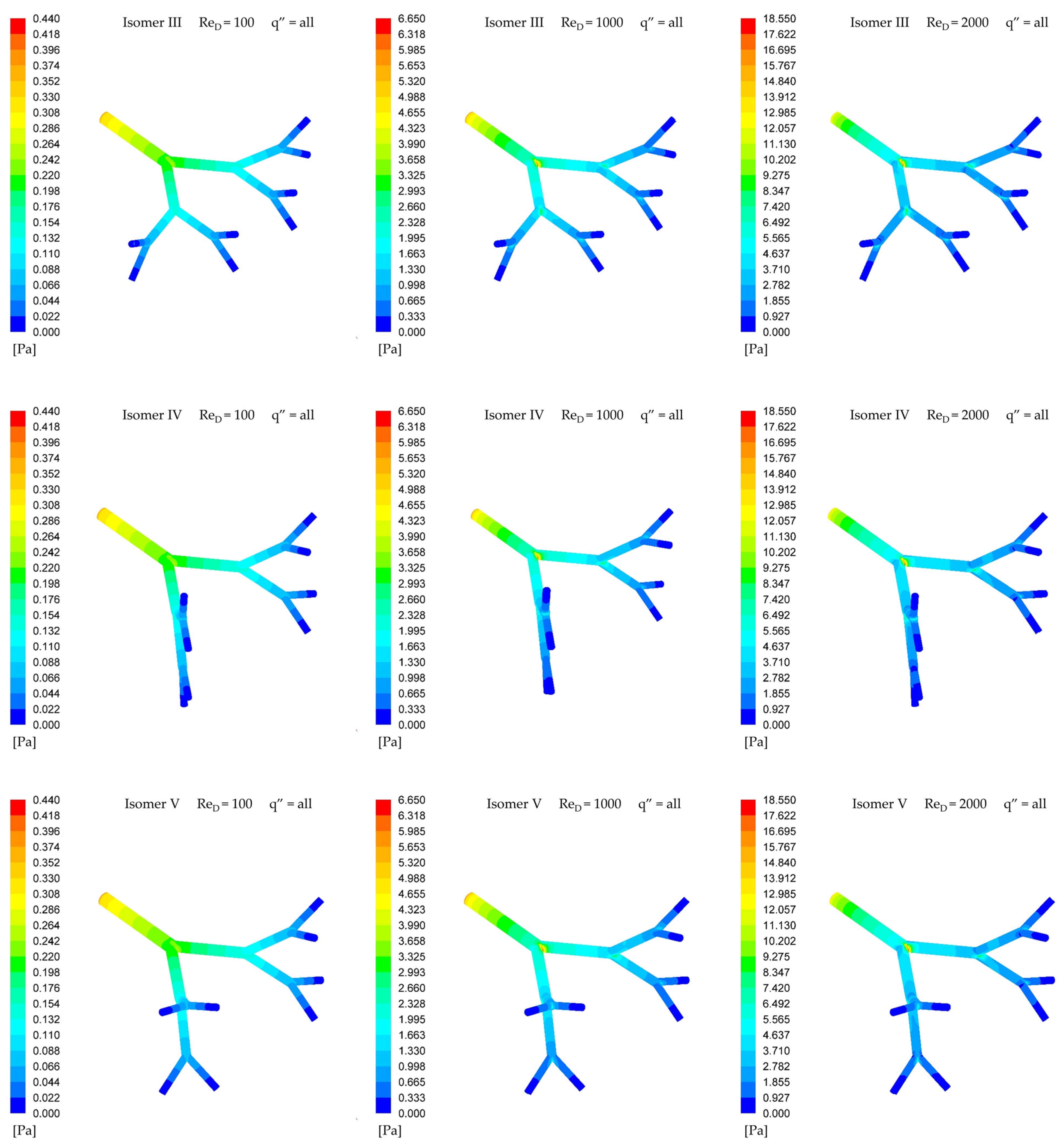
Figure 4 shows the static pressure distribution along the through self-similar symmetric branched. The names of the isomers are used to distinguish the self-similar structures, where the criteria for successive alignments are shown in Figure 3.
To better compare the static pressure fields for the same Reynolds numbers, equal scales were adopted with the criterion of the maximum pressure that occurs at the inlet surface of the model.
The static pressure profile is highly dependent on the Reynolds number and decreases as it approaches the outlet as branch levels increase. Also, it is observed that the flow resistance depends on the geometrical structure and the successive alignments between tubes at different branching levels.
Comparing the influence of successive alignments on the variation in the pressure drop, isomer I presents the lowest pressure, while isomer V presents the highest for the same Reynolds number. The calculated behavior is a ratio of 1.001 to 1.024 times between similar cases.
This increase in the pressure drop of out-of-plane isomers is attributed to the change in direction of the axis where the flow develops. In addition to the natural change due to bifurcation, there is also a change in plane, adding this component to localized losses. Also, since inertia forces are more significant at the first branching levels, isomer V is the most impacted when compared to the other isomers investigated.
Figure 5 shows Euler number versus Reynolds Number, that the Euler number decreases as the Reynolds number increases, this relationship holds true regardless of the heat transfer rates applied in the study. Considering the physical definition of the Reynolds number and the Euler number, this relationship indicates an increase in the inertial forces over the viscous forces and over the pressure forces. Assuming increased inertial forces, there is a better distribution of pressure gradients along the branched structure, which is identified in the static pressure fields in Figure 4.
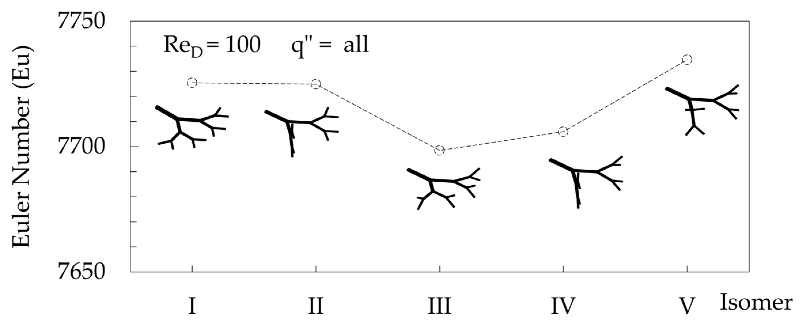
Figure 6 shows Euler number in the different self-similar symmetric branched structures. The effect of tube alignment between levels and the Reynolds number on the Euler number in different self-similar symmetric branched structures is shown for Reynolds numbers 100 and 2000 for all heat transfer rates applied in the study.
A clear trend emerges where the Euler number, which represents dimensionless pressure drop, tends to increase as the alignment between branching levels is removed. This study shows that the planar Isomer I has the lowest pressure drop, while the out-of-plane Isomer V has the highest. This difference is explained by the nature of localized pressure losses, which occur at features like junctions and bifurcations in addition to frictional losses. These localized losses are caused by the generation of energy-dissipating secondary flows. Isomer I is entirely planar, requiring the fluid to change direction only within a 2D plane. In contrast, out-of-plane isomers like Isomer V force the fluid to execute more complex, three-dimensional turns. Each change in plane introduces more intense secondary flows, leading to greater energy dissipation and a higher overall pressure drop.
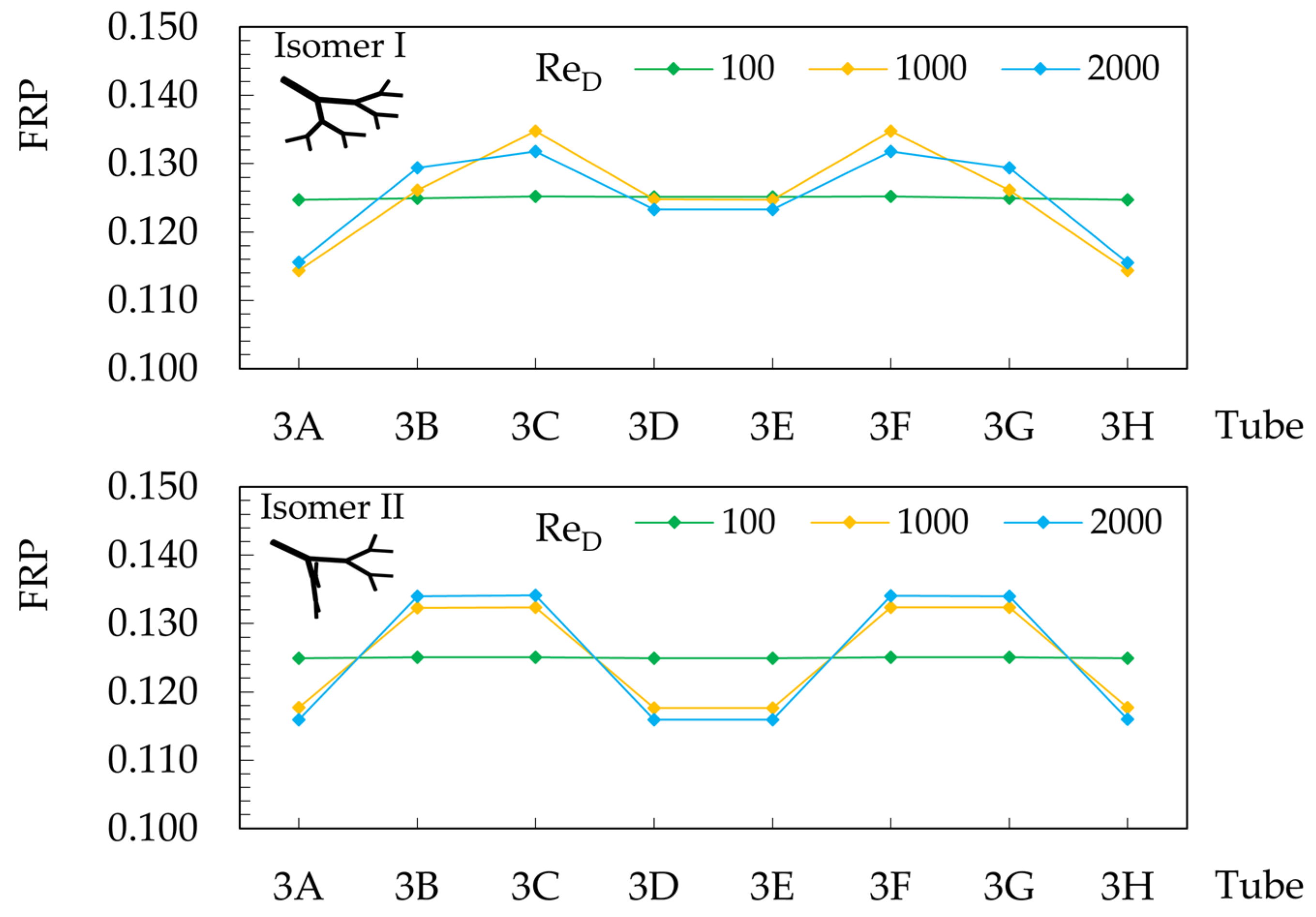
Figure 7 illustrates the dimensionless mass flow rate through each outlet tube of the self-similar networks. This plot shows the occurrence of the asymmetric flow rate that characterizes each isomer configurations with the effects of successive alignments between tubes of different branching levels.
The simple rule of successive alignments and the trends in the flow partition ratio along the tubes of self-similar flow structures proposed in Table 4 explains and justifies the findings of other research [11,12,14,15].
Other effects and rules can be highlighted with the results in Figure 6 and Table 4. The effects of isomer III, “a tube at level j aligned with a tube at level j − 2 causes asymmetric effects at j + 1, even if j + 1 is not aligned with j − 1.” In isomer IV, “paths that have alignments between tubes at different branch levels present worse flow distribution than paths that do not have alignment between tubes at different branch levels.” With isomer V, “successive misalignments contribute to better fluid distribution in the flow,” but this parameter alone is insufficient to equality in the distribution of fluid transport [12].
No less important is that the increase in inertia forces directly impacts the increase in asymmetries, since for ReD equal to 100 the FRP distribution tries to achieve equality of flow at each of the outlets, while for ReD equal to 1000 and 2000 there is a disorganization of the flow distribution, being greater for higher Reynolds numbers, thus FRP100 < FRP1000 < FRP2000.
A central finding of this study is that perfectly symmetric branching geometries produce asymmetric flow patterns, as shown in Figure 7. The primary physical mechanism driving this phenomenon is fluid inertia. Upon reaching a bifurcation, the fluid’s momentum prevents it from dividing perfectly between the two daughter branches, causing it to preferentially follow the path of least directional change. This creates a non-uniform velocity profile downstream of the split. This initial asymmetry is then propagated and amplified through subsequent branching levels in a cascade effect, where the successive alignments of tubes ensure that the asymmetries compound, leading to significant variations in the mass flow rate at the final outlets. The Reynolds number also has a critical impact on this asymmetry. At low ReD (e.g., 100), dominant viscous forces tend to dampen instabilities and promote a more even flow distribution. As ReD increases (e.g., to 2000), inertial forces become dominant, amplifying the effects at bifurcations and causing the fluid to deviate more significantly from an even split. This interplay of flow inertia, path curvature, and flow division at each bifurcation is the primary cause of the observed non-uniformity.
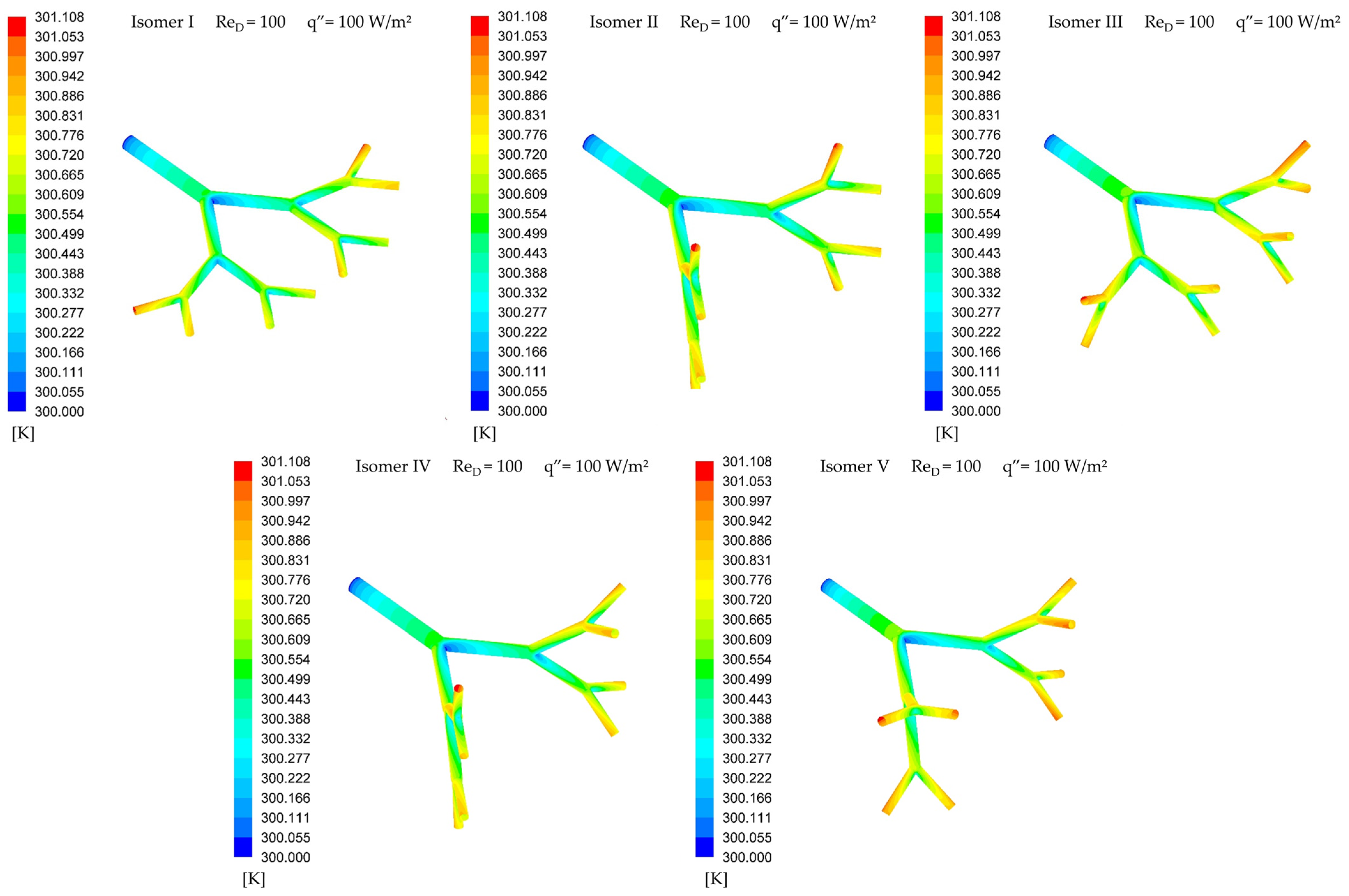
The following results incorporate heat transfer to further investigate these fluid dynamic effects. Figure 8 shows the temperature distribution along the through self-similar symmetric branched following the criteria for successive alignments shown in Figure 3.
All self-similar structures have similar temperature distribution characteristics along the branching levels. The higher branching levels have a higher wall temperature than the lower levels. As the flow divides, the velocity decreases and, consequently, the convection coefficient decreases. Another notable feature is branching level 3, where sister tubes supplied by the same parent tube have walls with distinct temperature gradients. Thus, there is a thermal asymmetry.
Table 5 shows the maximum dimensionless wall temperature with the variation in the Reynolds number in the different self-similar symmetric branched structures. Note that the maximum dimensionless wall temperature decreases as the Reynolds number increases and the thermal effect on the wall is imperceptible between the different self-similar structures.
For Reynolds numbers greater than 500, the variation in maximum wall temperature is negligible as the Reynolds number increases. Therefore, the investment in increasing pumping power is not justified by better thermal performance.
The reduction in thermal performance as the Reynolds number increases is associated with an increase in flow velocity, which contributes to a reduction in the thermal boundary layer and fluid dynamics boundary layer [39,40]. This, in turn, leads to an increase in frictional forces (i.e., an increase pressure drop) and a reduction in the contact time between the fluid and the heat exchange surface. Therefore, if self-similar structures are to be applied to heat exchangers, increasing the heat exchange area is mandatory to increase thermo-hydraulic performance.
The asymmetric effects measured through FRP were already known [11,12,14,15], but this work expands and advances the knowledge by identifying whether asymmetric effects in symmetric structures are significant for thermal properties. Responses regarding the maximum wall temperature were obtained; however, the temperature of the fluid outlet in each of the tubes of the branched structure remains to be determined.
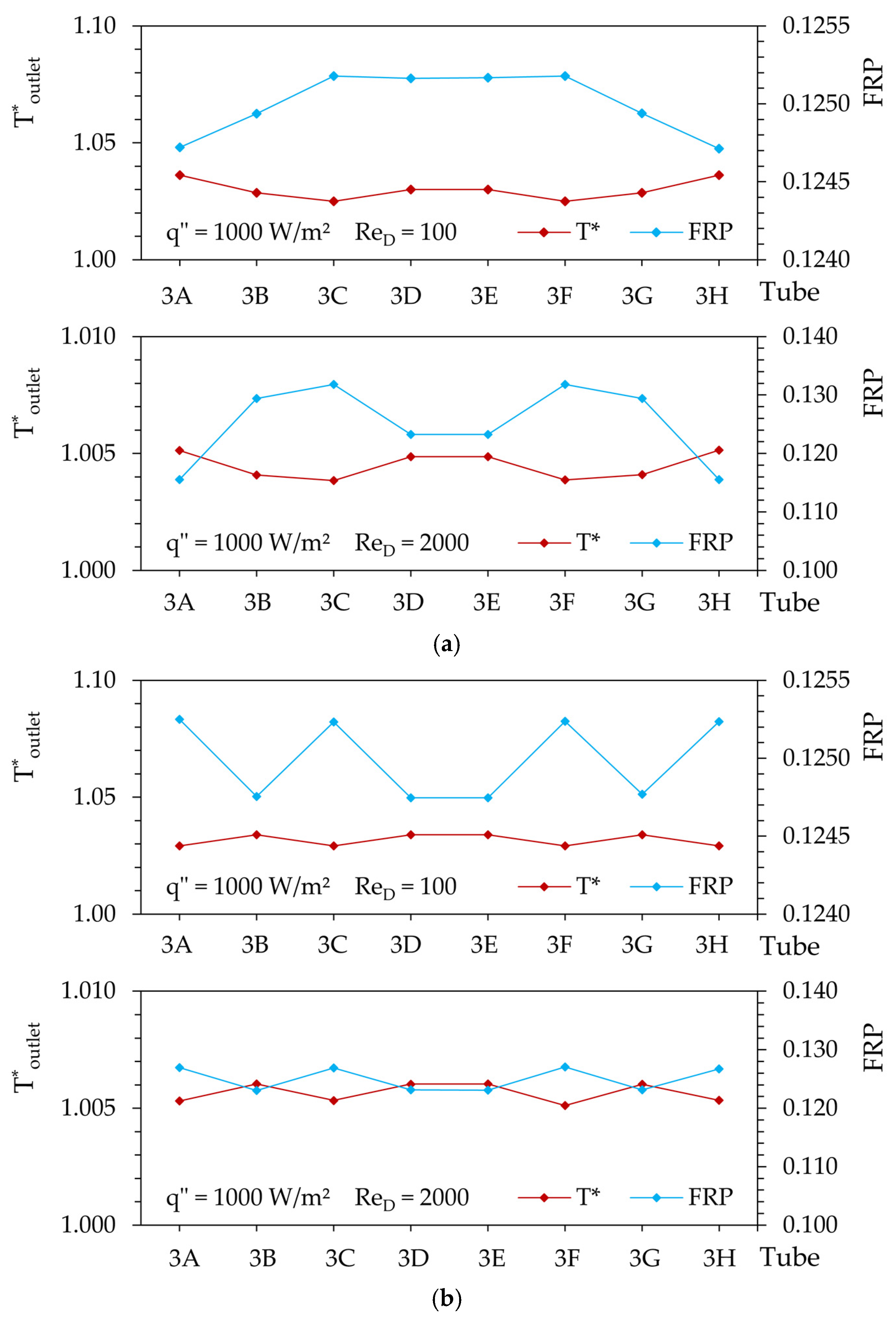
Figure 9 shows the dimensionless temperature at each of the outlets with the variation in the Reynolds number and heat transfer in the wall in the self-similar symmetric branched structures, in isomers I and V. These structures were selected for their distinct characteristics. Isomer I, which is easy to construct and has all its tubes contained in a single plane, is widely used in studies investigating flow in branched networks, such as rivers and the respiratory and circulatory systems. Isomer V, to the best of our knowledge, is the symmetric structure that best distributes the asymmetries associated with fluid flow.
The dimensionless outlet temperature curves are more similar to each other than the FRP curves, as the Reynolds number varies. In isomer I, this characteristic is highlighted, as successive alignments influence the FRP, while in isomer V, these alignments are reduced at the cost of increased pressure drop.
The outlet dimensionless temperature (T*) decreases when the dimensionless flow partitioning ratio (FRP) increases and the Reynolds number (ReD) increases. Thus, the paths that carry more fluid tend to have the lowest temperatures at the outlet. The outlet dimensionless temperature (T*) increases with increasing heat transfer (q″), but this is a relationship widely known through Newton’s law of cooling.
Tubes located in the peripheral path have a greater pressure drop compared to tubes in the central path [11]. As the peripheral path has a greater pressure drop, the fluid remains longer between the system’s inlet and outlet paths [40], favoring heat exchange between the fluid and the exchange surface, and this response is identified by a higher outlet dimensionless temperature.
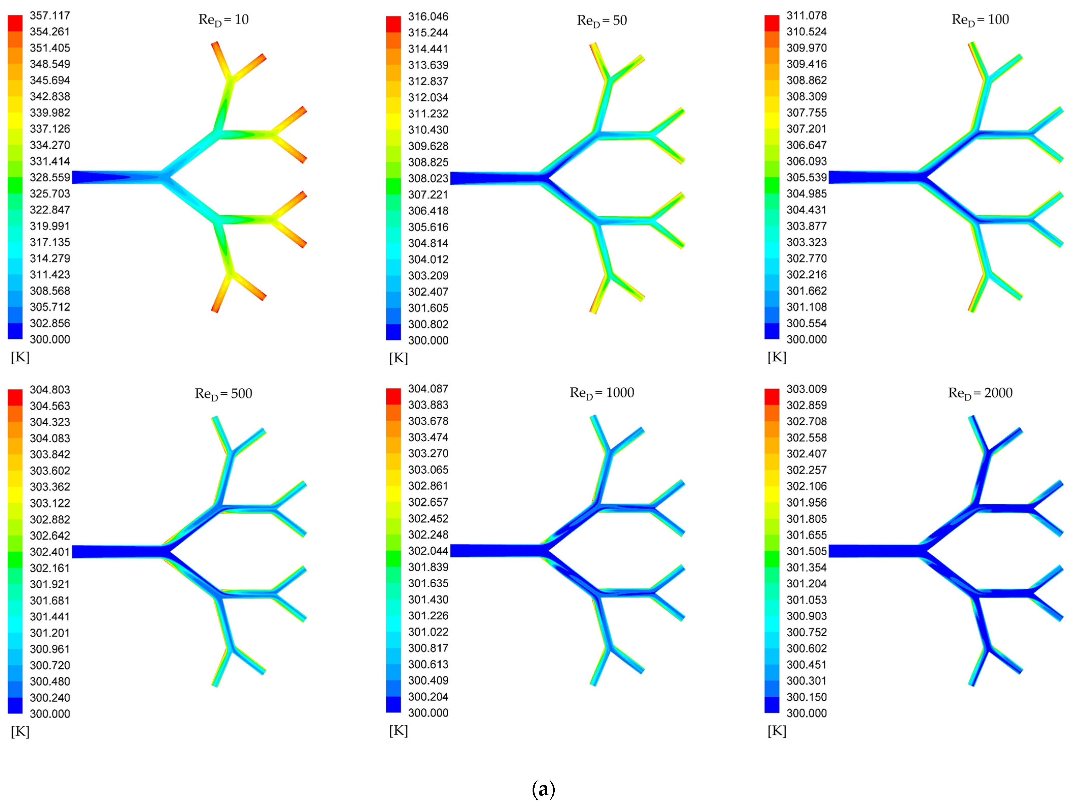
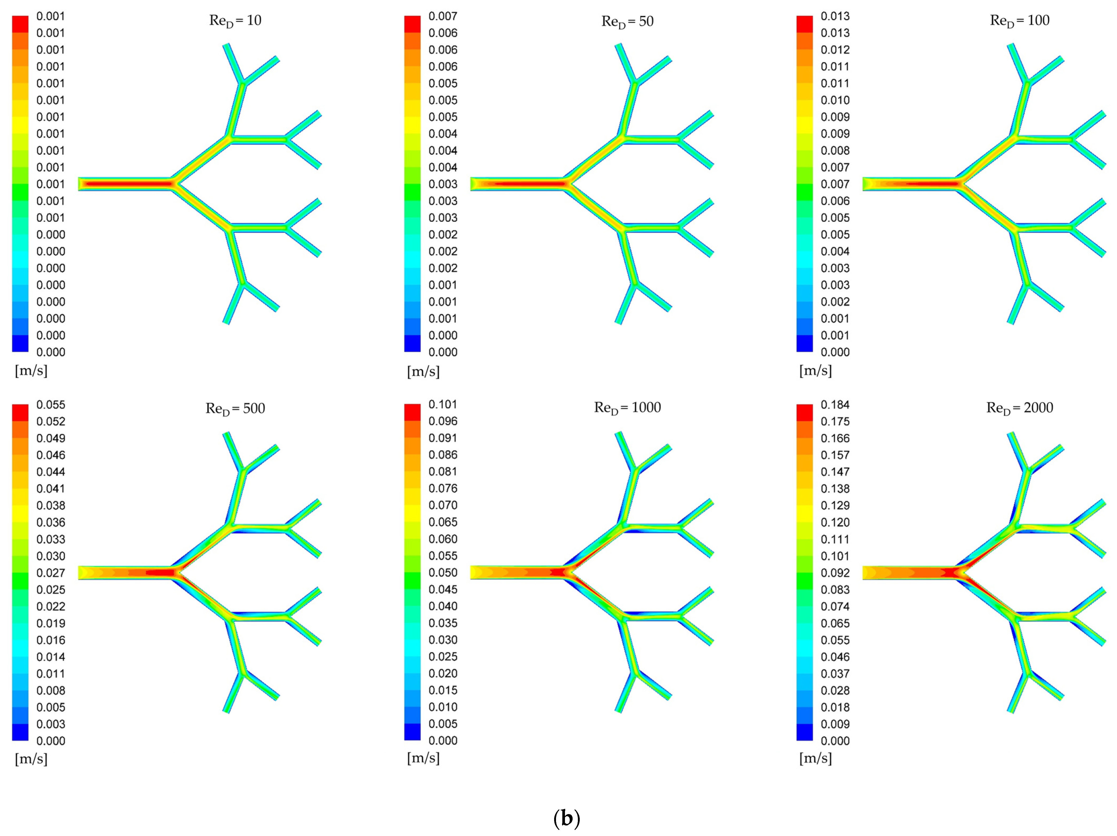
Figure 10 shows the central plane of the self-similar structure, on the colorimetric scale, the minimum and maximum values exactly represent the respective values found in the temperature and velocity fields. For the lowest Reynolds number, no thermal asymmetries are observed, but for ReD ≥ 50, differences are identified between the sister tubes at the second and third branching levels.
It is also possible to identify regions of high temperature immediately after the bifurcations; these are associated with recirculation regions characterized by regions of very low velocity near the wall.
With increasing inertia forces, the diffusive and convective effects become more evident and tend toward homogeneity of the system, but not in its entirety, as observed at ReD = 2000.
Observing the temperature field for ReD ≥ 100, the influence of the uneven distribution of flow along the branched structure becomes evident, now expressed through a thermal property. Tubes located in the peripheral path are different from the tubes in the central path.
While all observations for the temperature field can be compared to the velocity field, the use of thermal properties to identify fluid dynamic asymmetries is a more effective strategy. This is particularly true at higher branching levels where low velocities make it difficult to visualize asymmetries directly from the velocity field, a challenge that becomes most apparent for ReD > 500. The reason for this effectiveness lies in the direct link between heat transfer and fluid residence time. The amount of heat transferred to the fluid is a function of both the heat transfer coefficient and the time the fluid spends in contact with the heated surface. Paths that receive a lower mass flow rate (lower FRP) are characterized by lower average fluid velocities. This longer residence time allows the fluid in these paths to absorb more heat, resulting in a higher outlet temperature. Conversely, high-flow paths have shorter residence times and thus lower outlet temperatures. This relationship means that the outlet temperature distribution serves as a sensitive, thermally amplified map of the underlying mass flow distribution. Furthermore, the high-temperature regions observed immediately after bifurcations are physically significant, as they identify areas of very low velocity and flow recirculation where heat accumulates.
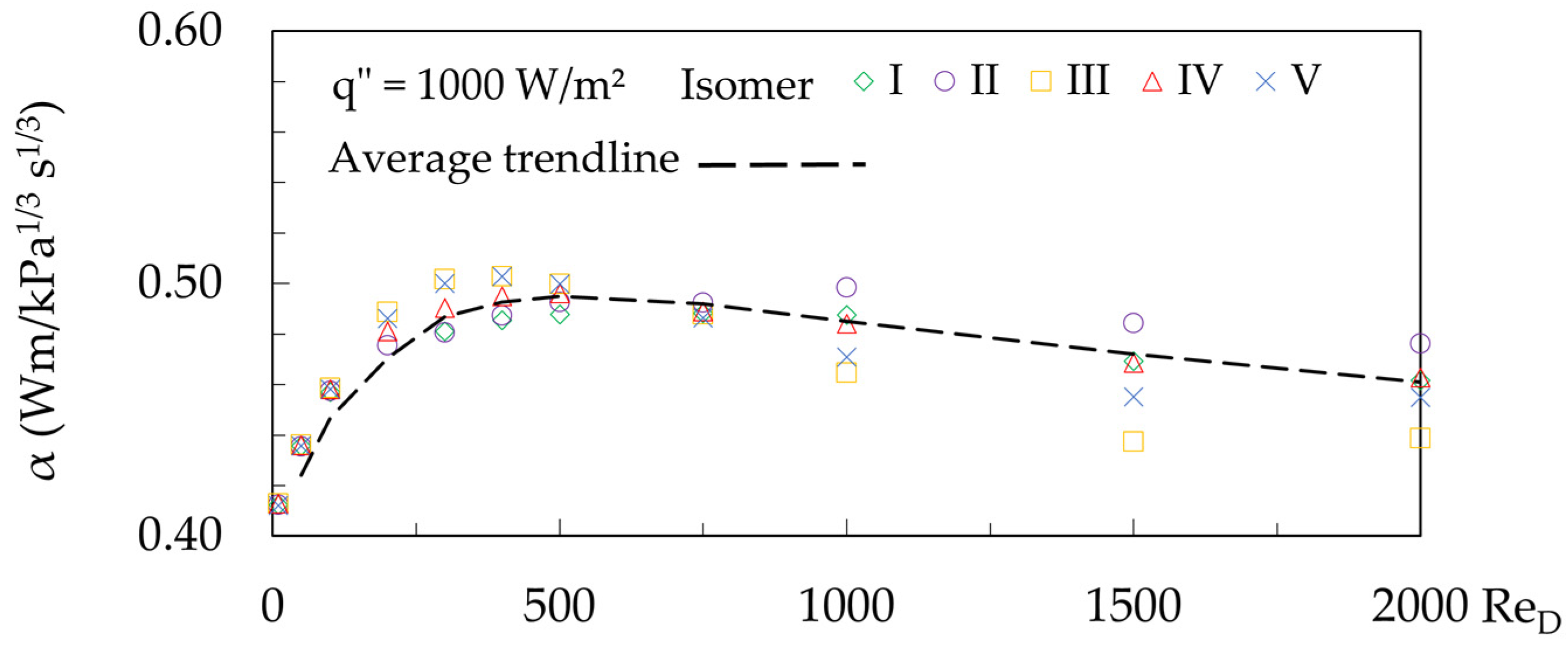
Having established how thermal distribution reflects flow performance, the overall thermo-fluid dynamic efficiency of the system is studied. Figure 11 shows the thermo-fluid dynamic efficiency, for q″ = 1000 W/m2. The thermo-fluid dynamic efficiency, calculated according to Equation (11), peaks at ReD~500. Note that the performance peaks near the Reynolds number 500. In the range 10 ≤ ReD ≤ 500, the curve slopes upward, and in the range 500 ≤ ReD ≤ 2000, it slopes downward. For fluid heating or cooling applications in tree-shaped structures, the choice of Reynolds number is crucial for maximizing performance. A notable thermal shift is observed in the system: for ReD ≤ 100 the wall temperature is generally higher than the fluid outlet temperature, while for ReD ≥ 100 this relationship can reverse, a trend valid for all structures in the studied heat transfer range.
As mentioned, Figure 11 reveals a performance peak near ReD~500. This indicates that simply increasing pumping power for higher Reynolds numbers becomes energetically unfeasible, with a ReD of 500 representing the limit for good energy utilization. This peak is the result of a fundamental trade-off between heat transfer enhancement and the required pumping power. The efficiency α balances this thermal benefit against the fluid dynamic cost. At low Reynolds numbers (ReD < 500), increasing the flow rate provides a significant benefit because it enhances the convective heat transfer coefficient, and the thermal gain outweighs the pumping cost. Conversely, at high Reynolds numbers (ReD > 500), further increasing the flow rate yields diminishing returns for heat transfer, as the fluid’s short residence time limits the amount of heat it can absorb. At this point, the pumping power penalty starts to dominate any marginal thermal benefit, causing the overall efficiency to decline. This peak, therefore, represents the optimal operating point where the system provides the most heat transfer for the least amount of pumping energy expended.
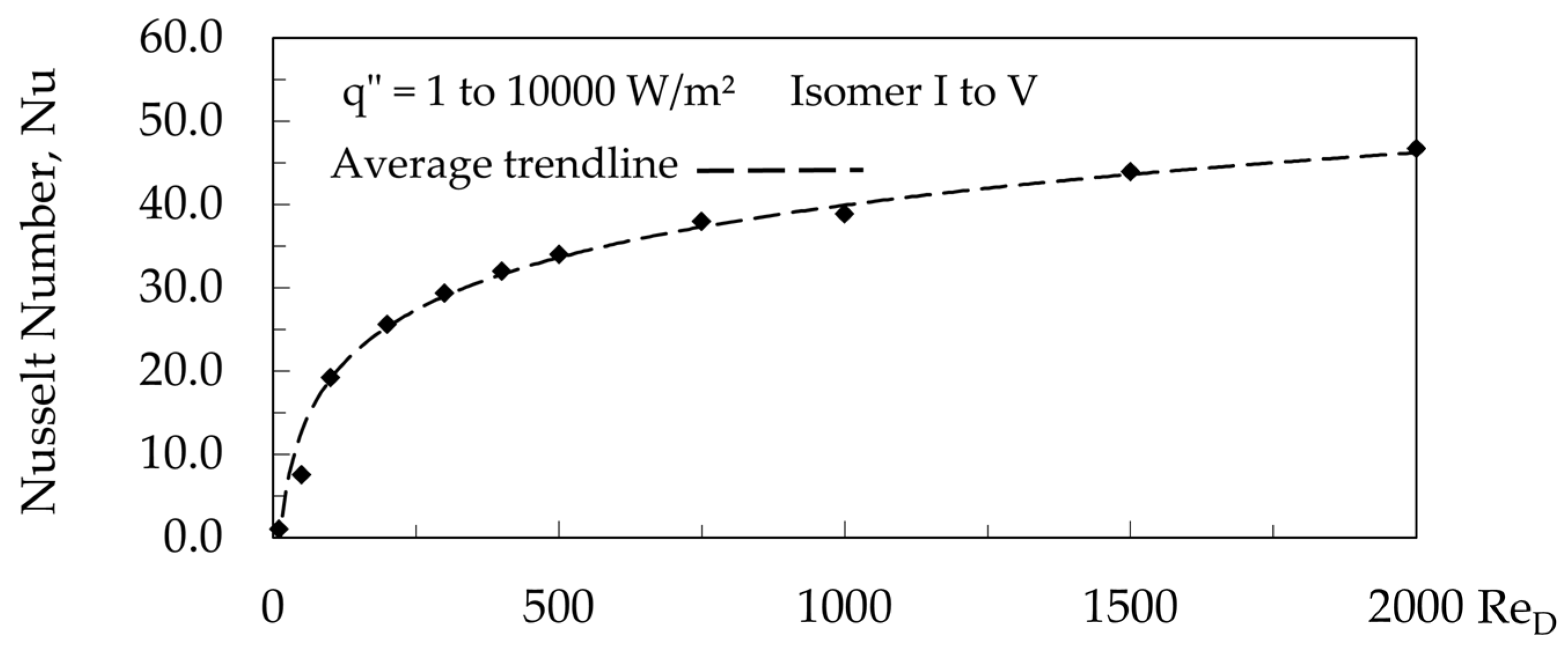
Figure 12 shows the overall Nusselt number versus Reynolds number. The fluid flow network has constant heat transfer along the walls. The curve slopes upward according the Reynolds number increases. Thus, the Nusselt number increases with increasing Reynolds number, indicating better heat transfer by convection compared to heat transfer by conduction. This increase is due to the fact that increasing the Reynolds number reduces the hydrodynamic boundary layer, intensifying fluid mixing and heat transfer between the tube surfaces.
For creeping flow ReD~10 viscous forces are significantly greater than inertia forces, with diffusive effects outweighing convective effects. Thus, for Nu~1, this means that convective heat transfer plays a minor role in overall heat exchange. The opposite occurs for ReD~2000, where inertia forces are significantly greater than viscous forces, and convective effects outweigh diffusive effects. Thus, for Nu~50, this means that convective heat transfer plays a greater role in overall heat exchange.

4. Conclusions

This study is about the flow of Newtonian fluids in self-similar dendritic networks with heat transfer. The main constraint is geometrical, that the volume at each branching level remains constant. It analyzes explicitly how fluid dynamics, heat transfer, and successive alignments between tubes at different branching levels affect the performance of the flow network. The key findings of this study are stated below.
In a complex structure designed according to the principle of structural isomers that have a constant volume restriction at each branching level, performance must be evaluated from different perspectives:
  • The structure that has the lowest pressure drop (i.e., isomer I) does not correspond to the structure that best distributes the flow symmetrically (i.e., isomer V). This result is obtained with and without heat transfer on the walls.
  • Changing the planes that contain the branching levels is not sufficient to correct asymmetries in symmetrical structures.
  • Heat transfer from the wall to the fluid generates insignificant effects on the flow asymmetry; that is, it does not amplify or attenuate asymmetric effects.
  • For the assessment of asymmetry in complex structures, thermal effects directly correlate with fluid dynamic effects. The use of heat transfer as a diagnostic tool is effective for identifying fluid dynamic asymmetries.
  • The response of thermal effects is more sensitive than that of fluid dynamic effects for low Reynolds numbers.
  • The trade-off between the pressure drop that increases pumping work and the positive effects on heat transfer was more significant in the range 200 ≤ ReD ≤ 500.
  • According to constructal law, the symmetrical structure that best achieves the objective is the isomer V.
Our results indicate that the design of complex flow networks, as designed using the Hess–Murray law and constructal law, is a good starting point for studies on self-similar flow networks. The use of heat transfer is recommended for investigations seeking to identify asymmetries at low Reynolds numbers.

Upcoming Studies

We are working hard to identify and advance studies of asymmetric effects associated with flows in complex structures. Our next steps are to
  • Explore and evaluate tree-shaped networks with more than three levels of branching;
  • Examine how homothetic relationships affect structures with asymmetrical bifurcations and their requirements for symmetric flows;
  • Explore the asymmetry of dimensional scales for applications with extremely high heat transfer density;
  • Explore engineering metrics like global and local Nusselt Number and pumping power per heat removed.

Author Contributions

Conceptualization, A.F.M. and L.R.; methodology, V.P.; software, V.P.; validation, V.P.; formal analysis, A.F.M. and V.P.; investigation, V.P. and A.F.M.; data curation, V.P.; writing—original draft preparation, V.P., A.F.M., F.Z. and L.R.; writing—review and editing, V.P., A.F.M., F.Z. and L.R.; supervision, A.F.M. and L.R. All authors have read and agreed to the published version of the manuscript.

Funding

Rocha, L.A.O. is a grant holder PQ CNPq (307791/2019-0). Zinani. F.S.F. is a grant holder PQ CNPq (Proc. No. 304832/2025-1). This research was funded by FCT-Portuguese Science and Technology Foundation, through the ICT multi-annual funding agreement, under the project UID/04683.

Data Availability Statement

Data will be made available on request.

Conflicts of Interest

The authors declare no conflicts of interest.

Appendix A. Geometric Parameters

Table A1. Branch level volume.
V0 (m3)V1 (m3)V2 (m3)V3 (m3)
0.00001767145867644260.00001767145867644260.00001767145867644260.0000176714586764426
Table A2. Lengths and diameters.
aDiL0 (m)L1 (m)L2 (m)L3 (m)D0 (m)D1 (m)D2 (m)D3 (m)
0.80.100000.078130.061040.047680.015000.012000.009600.00768

Appendix B. Svelteness Factor or Svelteness Number

Table A3. Area occupied and total volume.
aDiA (m2)VT (m3)Sv
0.80.07463111085204720.00007068583470577046.6
S v = A 1 / 2 V T 1 / 3
A = L 0 + L 1 cos α 2 + L 2 + L 3 cos α 2 · 2 L 1 sin α 2 + L 2 cos 90 α + L 3 cos α 2 cos 90 α
V T = π 4 D 0 2 L 0 + 2 D 1 2 L 1 + 4 D 2 2 L 2 + 8 D 3 2 L 3

Appendix C. Mesh Characteristics

Figure A1. Detailing of the prismatic layer in tube 0A.
Symmetry 17 01715 g0a1

References

  1. Bejan, A. Shape and Structure, From Engineering to Nature, 1st ed.; Cambridge University Press: Cambridge, UK, 2000. [Google Scholar]
  2. Weible, E.R. Morphometry of the Human Lung; Springer: Berlin/Heidelberg, Germany, 1963. [Google Scholar]
  3. McCulloh, K.A.; Sperry, J.S.; Adler, F.R. Water transport in plants obeys Murray’s law. Nature 2003, 421, 939–942. [Google Scholar] [CrossRef]
  4. Sarraf, K.; Launay, S.; Tadrist, L. Complex 3D-flow analysis and corrugation angle effect in plate heat exchangers. Int. J. Therm. Sci. 2015, 94, 126–138. [Google Scholar] [CrossRef]
  5. Mendoza Orbegoso, E.M.; Alcántara, J.A.; Verástegui, L.J.; Bengoa, J.C.; Marcelo-Aldana, D.; La Madrid Olivares, R.; Kyprianidis, K.G. Thermofluidics in Water-in-Glass Evacuated-Tube Solar Collectors Analysis Based on the Symmetry Conditions of Heat Flux and Tilt Angle. Symmetry 2025, 17, 44. [Google Scholar] [CrossRef]
  6. Bejan, A. Constructal-theory network of conducting paths for cooling a heat generating volume. Int. J. Heat Mass Transf. 1997, 40, 799–816. [Google Scholar] [CrossRef]
  7. Sauermoser, M.; Kjelstrup, S.; Kizilova, N.; Pollet, B.; Flekkøy, E.G. Seeking minimum entropy production for a tree-like flow-field in a fuel cell. Phys. Chem. 2020, 22, 6993–7003. [Google Scholar] [CrossRef] [PubMed]
  8. Fan, C.; Wu, C.L.; Wang, Y.; Wang, B.; Wang, J. Thermal metamaterials: From static to dynamic heat manipulation. Phys. Rep. 2024, 1077, 1–111. [Google Scholar] [CrossRef]
  9. Ehlers, H.; Olivier, T.; Trietsch, S.J.; Vulto, P.; Burton, T.P.; Van Den Broek, L.J. Microfluidic artery-on-a-chip model with unidirectional gravity-driven flow for high-throughput applications. Lab Chip 2025, 25, 2376–2389. [Google Scholar] [CrossRef]
  10. Emerson, D.R.; Cieslicki, K.; Gu, X.; Barber, R.W. Biomimetic design of microfluidic manifolds based on a generalised Murray’s law. Lab Chip 2006, 3, 447–454. [Google Scholar] [CrossRef]
  11. Pepe, V.R.; Miguel, A.F.; Zinani, F.S.F.; Rocha, L.A.O. New insights into creeping fluid flow through dendritic networks: A constructal view. Int. Commun. Heat Mass Transf. 2022, 139, 106409. [Google Scholar] [CrossRef]
  12. Pepe, V.R.; Miguel, A.F.; Zinani, F.S.F.; Rocha, L.A.O. Fluid Flow Through Isomeric Constructal Networks of Tubes. J. Porous Media 2024, 27, 1–18. [Google Scholar] [CrossRef]
  13. Pepe, V.; Miguel, A.F.; Zinani, F.; Rocha, L. Numerical Study of Carreau Fluid Flow in Symmetrically Branched Tubes. Symmetry 2025, 17, 48. [Google Scholar] [CrossRef]
  14. Andrade Jr, J.S.; Alencar, A.M.; Almeida, M.P.; Mendes Filho, J.; Buldyrev, S.V.; Zapperi, S.; Stanley, H.E.; Suki, B. Asymmetric flow in symmetric branched structures. Phys. Rev. Let. 1998, 81, 926–929. [Google Scholar] [CrossRef]
  15. Pradhan, K.; Guha, A.; Halder, P.K. Characteristics of pressure drop, mass flow distribution and flow asymmetry in three-dimensional branching networks based on model human bronchial tree. Z. Angew. Math. Mech. 2020, 100, e201900022. [Google Scholar] [CrossRef]
  16. Majumdar, A.; Alencar, A.M.; Buldyrev, S.V.; Hantos, Z.; Lutchen, K.R.; Stanley, H.E.; Suki, B. Relating airway diameter distributions to regular branching asymmetry in the lung. Phys. Rev. Lett. 2005, 95, 168101. [Google Scholar] [CrossRef]
  17. Deng, D.X.; Zeng, L.; Sun, W. A review on flow boiling enhancement and fabrication of enhanced microchannels of microchannel heat sinks. Int. J. Heat Mass Transf. 2021, 175, 121332. [Google Scholar] [CrossRef]
  18. Wang, W.; Li, Y.J.; Zhang, Y.N.; Li, B.; Sundén, B. Analysis of laminar flow and heat transfer in an interrupted microchannel heat sink with different shaped ribs. J. Therm. Anal. Calorim. 2020, 140, 1259–1266. [Google Scholar] [CrossRef]
  19. Chai, L.; Xia, G.D.; Wang, H.S. Laminar flow and heat transfer characteristics of interrupted microchannel heat sink with ribs in the transverse microchambers. Int. J. Therm. Sci. 2016, 110, 1–11. [Google Scholar] [CrossRef]
  20. Hess, W.R. Über die periphere Regulierung der Blutzirkulation. Arch. Ges. Physiol. 1917, 168, 439–490. [Google Scholar] [CrossRef]
  21. Murray, C.D. The physiological principle of minimum work. I. The vascular system and the cost of blood volume. Proc. Natl. Acad. Sci. USA 1926, 12, 207–214. [Google Scholar] [CrossRef]
  22. Murray, C.D. The physiological principle of minimum work applied to the angle of branching of arteries. J. Gen. Physiol. 1926, 9, 835–841. [Google Scholar] [CrossRef] [PubMed]
  23. Bejan, A.; Lorente, S. Design with Constructal Theory, 1st ed.; John Wiley & Sons: Hoboken, NJ, USA, 2008. [Google Scholar]
  24. Miguel, A.F. Low dissipative configuration in flow networks subject to constraints. Phys. D 2014, 467, 13426. [Google Scholar] [CrossRef]
  25. Martin, K.; Campos-Celador, A.; Escudero, C.; Gómez, I.; Sala, J.M. Analysis of a thermal bridge in a guarded hot box testing facility. Energy Build. 2012, 50, 139–149. [Google Scholar] [CrossRef]
  26. Martin, K.; Flores, I.; Escudero, C.; Apaolaza, A.; Sala, J.M. Methodology for the calculation of response factors through experimental tests and validation with simulation. Energy Build. 2010, 42, 461–467. [Google Scholar] [CrossRef]
  27. Xiang, X.; Zhao, K.; Liu, X.; Jiang, Y. Cooling performance comparison of radiant floor system and all-air system with solar radiation. Energy Procedia 2015, 78, 2322–2327. [Google Scholar] [CrossRef]
  28. Zaidan, M.J.; Alhamdo, M.H. Comparative Thermal Analysis of Serpentine and Spiral Tube Configurations in Concrete Solar Collectors Using Numerical and Experimental Approaches. Heat Transf. 2025, 4, 3697–3722. [Google Scholar] [CrossRef]
  29. Ismail, M. Experimental and numerical analysis of heat sink using various patterns of cylindrical pin-fins. Int. J. Thermofluids 2024, 23, 100737. [Google Scholar] [CrossRef]
  30. Patankar, S.V. Numerical Heat Transfer and Fluid Flow; McGraw-Hill: New York, NY, USA, 1980. [Google Scholar]
  31. Schlichting, H.; Kestin, J. Boundary Layer Theory; McGraw-Hill: New York, NY, USA, 1961. [Google Scholar]
  32. Bejan, A. Convection Heat Transfer, 3rd ed.; John Wiley & Sons: Hoboken, NJ, USA, 2013. [Google Scholar]
  33. Roache, P.J. Quantification of uncertainty in computational fluid dynamics. Annu. Rev. Fluid Mech. 1997, 29, 123–160. [Google Scholar] [CrossRef]
  34. Celik, I.B.; Ghia, U.; Roache, P.J.; Freitas, C.J.; Coleman, H.; Raad, P.E. Procedure for estimation and reporting of uncertainty due to discretization in CFD applications. J. Fluids Eng. 2008, 130, 078001. [Google Scholar] [CrossRef]
  35. Zhang, C.H.; Liu, Y.; So, R.M.C.; Phan-Thien, N. The Influence of Inlet Velocity Profile on Three-Dimensional Three-Generation Bifurcating Flows. Comput. Mech. 2002, 29, 422–429. [Google Scholar] [CrossRef]
  36. Webb, R.L.; Eckert, E.R. Application of rough surfaces to heat exchanger design. Int. J. Heat Mass Transf. 1972, 15, 1647–1658. [Google Scholar] [CrossRef]
  37. Ahmed, M.; Yusoff, M.; Ng, K.C.; Shuaib, N. The effects of wavy-wall phase shift on thermal-hydraulic performance of Al2O3-water nanofluid flow in sinusoidal-wavy channel. Therm. Eng. 2014, 4, 153–165. [Google Scholar] [CrossRef]
  38. Kumar, R.; Kumar, A.; Goel, V. Performance improvement and development of correlation for friction factor and heat transfer using computational fluid dynamics for ribbed triangular duct solar air heater. Renew. Energy 2019, 131, 788–799. [Google Scholar] [CrossRef]
  39. Prabhakara Rao, B.; Sunden, B.; Das, S.K. An experimental and theoretical investigation of the effect of flow maldistribution on the thermal performance of plate heat exchangers. J. Heat Transf. 2005, 127, 332–343. [Google Scholar] [CrossRef]
  40. Fakheri, A. Heat Exchanger Efficiency. J. Heat Transf. 2007, 129, 1268–1276. [Google Scholar] [CrossRef]
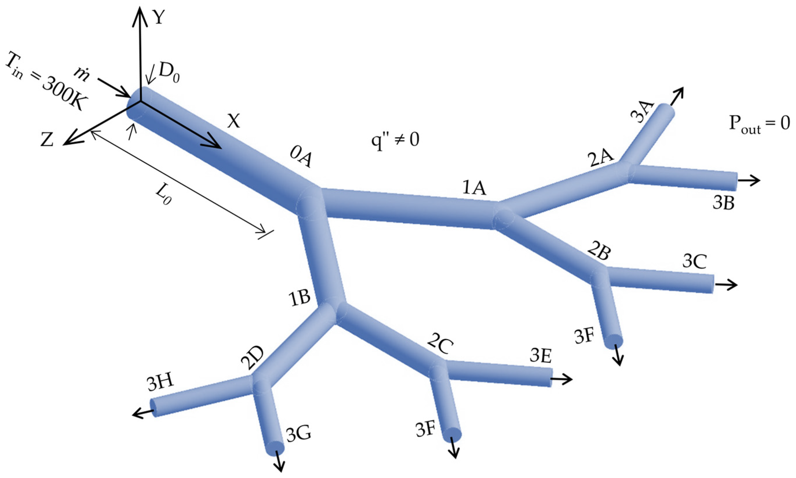
Figure 1. Planar self-similar fluidic structure with three symmetric branching levels and circular sections to transport Newtonian fluids with heat transfer in the wall (i.e., isomer I).
Symmetry 17 01715 g001
Figure 2. Isomer self-similar fluidic structure with three symmetric branching levels: (a) isomer II, (b) isomer III, (c) isomer IV and (d) isomer V.
Symmetry 17 01715 g002
Figure 3. Alignment criterion between pipes of different branching levels in self-similar fluidic structure, isomer I to V.
Symmetry 17 01715 g003
Figure 4. Contours of static pressure for a network designed for aD = 0.80.
Symmetry 17 01715 g004aSymmetry 17 01715 g004b
Figure 5. Euler number (Equation (8)) versus Reynolds number.
Symmetry 17 01715 g005
Figure 6. Euler number (Equation (8)) versus self-similar structures (geometrical isomer).
Symmetry 17 01715 g006aSymmetry 17 01715 g006b
Figure 7. Dimensionless flow partitioning ratio (Equation (9)) versus Reynolds number for outlet tubes.
Symmetry 17 01715 g007aSymmetry 17 01715 g007b
Figure 8. Temperature field for a network designed for aD = 0.80.
Symmetry 17 01715 g008
Figure 9. Outlet dimensionless temperature (Equation (10)) versus dimensionless flow partitioning ratio (Equation (9)) for (a) isomer I and (b) isomer V.
Symmetry 17 01715 g009
Figure 10. (a) Temperature and (b) velocity field in the central plane for isomer I with q″ = 1000 W/m2 and designed according to aD = 0.80.
Symmetry 17 01715 g010aSymmetry 17 01715 g010b
Figure 11. Thermo-fluid dynamic efficiency (Equation (11)) versus Reynolds number for q″ = 1000 W/m2.
Symmetry 17 01715 g011
Figure 12. Nusselt number (Equation (12)) versus Reynolds number for q″ = 1 to 1000 W/m2.
Symmetry 17 01715 g012
Table 1. Values for geometric parameters and boundary condition.
Geometric Parameters Boundary Condition
Vi1.767 m30.000118 to 0.023633 kg/s
θi750Tin300 K
aDi2−1/3q″1 to 1000 W/m2
L00.100 muwall0 m/s
D00.015 mPout0 Pa
Table 2. Grid convergence index at, aD = 0.8, ReD = 2000.
Isomer
IIIIIIIVV
EuN1677.64684.78677.33688.12694.36
EuN2675.53683.52674.96686.09692.30
EuN3540.57569.31570.98562.01544.00
N11,808,9082,186,4381,752,7432,050,3582,037,221
N2240,490291,860235,690275,100273,337
N335,20840,09832,34438,59238,792
r211.9591.9521.9571.9531.953
r321.8971.9391.9381.9251.917
Eu ext 21677.67684.79677.38688.11694.39
Eu ext 32677.67684.79677.38690.07694.39
ε210.31%0.18%0.350.14%0.30%
ε3219.98%16.71%15.4118.44%21.42%
GCI210.50%0.24%0.97%0.54%0.43%
GCI3239.59%23.21%44.57%36.99%36.56%
Table 3. Comparison of geometric relationships for validation of the computational model.
Flow StructureZhang et al. (2002) [35]Present Numerical Model Adapted with Two Branching Level
Symmetry 17 01715 i001Symmetry 17 01715 i002
Number of branching levels22
L00.0107 m0.0107 m
L10.0090 m0.0090 m
L20.0076 m0.0076 m
D00.0035 m0.0035 m
D10.0028 m0.0028 m
D20.0023 m0.0023 m
L0/D03.013.01
L1/D13.213.21
L1/D13.303.30
aD0.780.78
θ70°70°
ΔP* = ΔP∙ρ∙u219.4120.47
ε = Δ P * r e f Δ P * p r e s e n t Δ P * r e f -----0.054
Table 4. Isomer and tube alignment.
IsomerLevel 1Level 2Level 3
IFRP1A = FRP1BFRP2A < FRP2B
FRP2C > FRP2D
FRP3A < FRP3B
FRP3C > FRP3D
FRP3E < FRP3F
FRP3G > FRP3H
IIFRP1A = FRP1BFRP2A = FRP2B
FRP2C = FRP2D
FRP3A < FRP3B
FRP3C > FRP3D
FRP3E < FRP3F
FRP3G > FRP3H
IIIFRP1A = FRP1BFRP2A < FRP2B
FRP2C > FRP2D
FRP3A < FRP3B
FRP3C > FRP3D
FRP3E < FRP3F
FRP3G > FRP3H
IVFRP1A = FRP1BFRP2A = FRP2B
FRP2C = FRP2D
FRP3A > FRP3B
FRP3C > FRP3D
FRP3E < FRP3F
FRP3G > FRP3H
VFRP1A = FRP1BFRP2A = FRP2B
FRP2C = FRP2D
FRP3A > FRP3B
FRP3C > FRP3D
FRP3E < FRP3F
FRP3G < FRP3H
Table 5. Maximum dimensionless wall temperature (Equation (10)) for Reynolds number (10 to 2000) and q″ = 1000 W/m2).
q″ReDIsomer
IIIIIIIVV
1000 W/m2101.19051.19001.19031.18991.1899
501.05351.05071.05131.05091.0502
1001.03701.03501.03471.03521.0345
2001.02161.02501.02271.02501.0243
3001.01931.01951.01861.01951.0189
4001.01711.01671.01661.01671.0168
5001.01601.01621.01611.01611.0162
7501.01501.01521.01501.01521.0152
10001.01361.01291.01371.01291.0129
15001.01011.00931.01021.00921.0092
20001.00331.00321.00321.00321.0032
Disclaimer/Publisher’s Note: The statements, opinions and data contained in all publications are solely those of the individual author(s) and contributor(s) and not of MDPI and/or the editor(s). MDPI and/or the editor(s) disclaim responsibility for any injury to people or property resulting from any ideas, methods, instructions or products referred to in the content.