Article

Numerical Simulation Study Considering Discontinuous Longitudinal Joints in Soft Soil under Symmetric Loading

1
School of Rail Transportation, Soochow University, Suzhou 215123, China
2
School of Transportation and Civil Engineering, Nantong University, Nantong 226019, China
*
Author to whom correspondence should be addressed.
Symmetry 2024, 16(6), 650; https://doi.org/10.3390/sym16060650
Submission received: 29 April 2024 / Revised: 16 May 2024 / Accepted: 21 May 2024 / Published: 24 May 2024

Abstract

:
In shield tunneling, the joint is one of the most vulnerable parts of the segmental lining. Opening of the joint reduces the overall stiffness of the ring, leading to structural damage and issues such as water leakage. Currently, the Winkler method is commonly used to calculate structural deformation, simplifying the interaction between segments and soil as radial and tangential Winkler springs. However, when introducing connection springs or reduction factors to simulate the joint stiffness of segments, the challenge lies in determining the reduction coefficient and the stiffness of the springs. Currently, the hyperstatic reflection method cannot simulate the discontinuity effect at the connection of the tunnel segments, while the state space method overlooks the nonlinear interaction between the tunnel and the soil. Therefore, this paper proposes a numerical simulation method considering the interaction between the tunnel and the soil, which is subjected to compression rather than tension, and the discontinuity of the joints between the segments. The model structure and external load are symmetrical, resulting in symmetrical calculation results. This method is based on the soft soil layers and shield tunnel structures of the Shanghai Metro, and the applicability of the model is verified through deformation calculations using three-dimensional laser scanning point clouds of sections from the Shanghai Metro Line 5. When the subgrade reaction coefficient is 5000 k N / m 3 , the model can effectively simulate the deformation of operational tunnels. By adjusting the bending stiffness of individual connection springs, we investigate the influence of bending stiffness reduction on the bending moment, radial displacement, and rotational displacement of the ring. The results indicate that a decrease in joint bending stiffness significantly affects the mechanical response of the ring, and the extent and degree of this influence are correlated with the joint position and the magnitude of joint bending stiffness.

1. Introduction

The construction of urban underground space is an integral part of urban development. The design, construction, and operation management of underground space are crucial aspects that require continuous improvement and optimization in the urban development process. This area also receives significant attention from scholars. Shield tunneling, due to its high safety, fast construction speed, and high quality, has been widely used in urban underground construction. Each ring of the tunnel is assembled by connecting and assembling multiple prefabricated segments with bolts, and the complete tunnel is obtained by the shield machine pushing forward layer by layer. As the main part of the tunnel, the lining bears and transmits loads. The connection between the segments is one of the weak points in the tunnel structure and is also one of the main research directions for scholars.
Current research has shown that the mechanical performance of joints has a significant impact on the functionality of the segment structure, reducing the overall stiffness of the segment, increasing structural deformation, and leading to issues such as structural damage and joint leakage. Moreover, the mechanical behavior of longitudinal joints is highly nonlinear, mainly divided into the following three stages: the elastic stage; in which concrete is partially plastic while steel bolts remain elastic; the plastic stage; and the outer concrete contact stage [1]. In the past few decades, scholars have studied the structural performance of joints through numerical simulations [2,3,4], experimental methods [5,6,7,8], and analytical approaches [9]. Among them, numerical simulation methods are widely used due to their strong applicability and low cost, but determining parameters remains a key and challenging aspect of numerical simulation methods.
At the same time, some analytical models based on simplified assumptions are widely adopted due to their high computational efficiency and ease of implementation. Oreste [10] proposed, for the first time, the Hyperstatic Reaction Method (HRM) for tunnel structure analysis based on a beam-spring model. Do [11], based on HRM, uses the FEM framework to develop a specific code called FEMSL to perform HRM calculations. Current HRM allows for the consideration of arbitrary distributions of segment joints along the tunnel boundary.
In the current methods considering the influence of joint bending stiffness on the ring in shield tunnels, Do [12] proposed two different methods based on their assumptions, namely the direct method and the indirect method, where tunnel segments are simulated as beam elements or shell elements. The indirect method estimates the effect of joints on tunnel behavior by introducing a reduction coefficient for tunnel lining stiffness, but this reduction coefficient varies with burial depth [13]. The direct method simulates the mechanical effects of joints by introducing springs, with the connection between segments simplified to springs without length, where the spring adopts the node bending stiffness K ϴ , defined as the unit length moment required for the unit rotation of longitudinal nodes. Beam or shell spring models can better characterize the mechanical performance of nodes, but their bending stiffness is affected by the highly nonlinear and discontinuous characteristics of joints. Additionally, the stiffness of nodes under positive bending moments is higher than that under negative bending moments [1]. This makes it difficult to determine the parameters of joints in numerical simulations and analytical calculations. In earlier methods, the joint bending stiffness K ϴ was assumed to be constant. Wang [14] proposed treating nodes as a set of discontinuous springs and solving them using the state-space method to ensure the continuity of internal forces and the discontinuity of displacements. Zhong [5] proposed using a bilinear model to fit the relationship between joint bending angle and rotation. Do [12] used simplified bilinear joint bending stiffness to study the effects of joint springs, Young’s modulus, and lateral pressure coefficient under different foundation conditions. Chen [15] established a new method for dynamic response analysis of shield tunnel circular segment linings based on the State Space Method and D’Alembert’sprinciple. Zhou [16] conducted experiments on the mechanical properties of ductile iron joint plates in shield tunnels with high internal water pressure and deep burial. Chen [13] proposed an analytical solution for the secondary reinforcement of tunnel linings based on the state-space method; subsequently, the commonality of joint mechanical behavior gradually became recognized by researchers, and nonlinear behavior was adopted to simulate joint behavior. Huang [17] combined the state–space method with the Newton–Steffensen iterative procedure to establish and solve equations for non-tensioned foundations and nonlinear nodes. Do [11] proposed a numerical method for segmented tunnel lining hyperstatic force analysis, directly considering the influence of segment node by using a fixed ratio represented by a non-length rotational spring determined by nonlinear rotational stiffness, as it is closer to the true behavior of joints than linear or bilinear behavior. Liu [18] proposed a nonlinear model of an SPCC-reinforced tunnel structure with reasonable effectiveness and accuracy. Generally, axial force, shear force, and bending moment can all be transmitted through connections. However, the effects of axial and shear deformations can be neglected as they are relatively small compared to the bending deformations of most connections. Therefore, in a semi-rigid framework, only the rotational deformations of nodes are typically considered, described by their moment–rotation (M-ϴ) relationship. Currently, the calculation of nonlinear effects at segment joints is typically based on the Hyperstatic Reflection Method (HRM), achieved by continuously updating the rotational stiffness during the analysis process. However, discontinuous deformations often cannot be solved using this method.
In recent years, a new tunnel structural analysis method called the State Space Method has been proposed [13]. It considers the nonlinear behavior of joints, but neglects the nonlinear interaction between the tunnel and the surrounding soil. Zhang [19] argued that neglecting soil nonlinearity would underestimate tunnel convergence, leading to more complex calculations of lining structures. Meanwhile, the Winkler method simplifies the interaction between the tunnel structure and the soil into a set of radial and tangential stiffness springs. Yuan [20], based on Zhang’s [19] formula, estimated and analyzed soil stiffness springs. Sugimoto [21] proposed a tunnel lining frame structure analysis model based on nonlinear subgrade reaction coefficient curves. Anh The Pham [22] conducted parameter studies based on nonlinear subgrade reaction coefficient curves, indicating the occurrence of tensile stresses in shallow-buried tunnels in soft soil foundations. Although nonlinear characteristics of ground reaction have been proposed in analytical calculations, they have not been widely applied in numerical simulations.
Considering the nonlinear effects of the interaction between tunnel structures and soil, as well as the discontinuous features between tunnel segments, scholars have conducted a series of related studies based on Shanghai’s soft soil conditions [1,15,20,23,24,25,26]. However, their validation methods often rely on numerical simulation data and indoor test data from scholarly literature, making it difficult to assess internal forces and deformations under complex loading conditions for operational tunnels. Therefore, this paper adopts numerical simulation to implement a beam–spring discontinuous model, simultaneously considering the compression-only effects of tunnel structures and soil. A finite element model is established based on the soft soil layers and segment patterns of Shanghai Metro Line 5, and the applicability of the model is verified by calculating deformations using three-dimensional laser scanning point clouds of sections from Shanghai Metro Line 5. The method for processing point clouds is based on the author’s previous research [27,28,29]. Suitable subgrade reaction coefficients and lateral pressure coefficients are determined by adjusting the bending stiffness of the beam–spring model’s connection springs for ring segment joints. The influence of determining the joint bending stiffness on the numerical calculation results for the entire ring is analyzed, providing new insights for calculating internal forces and deflections in ring structures with reduction coefficients.

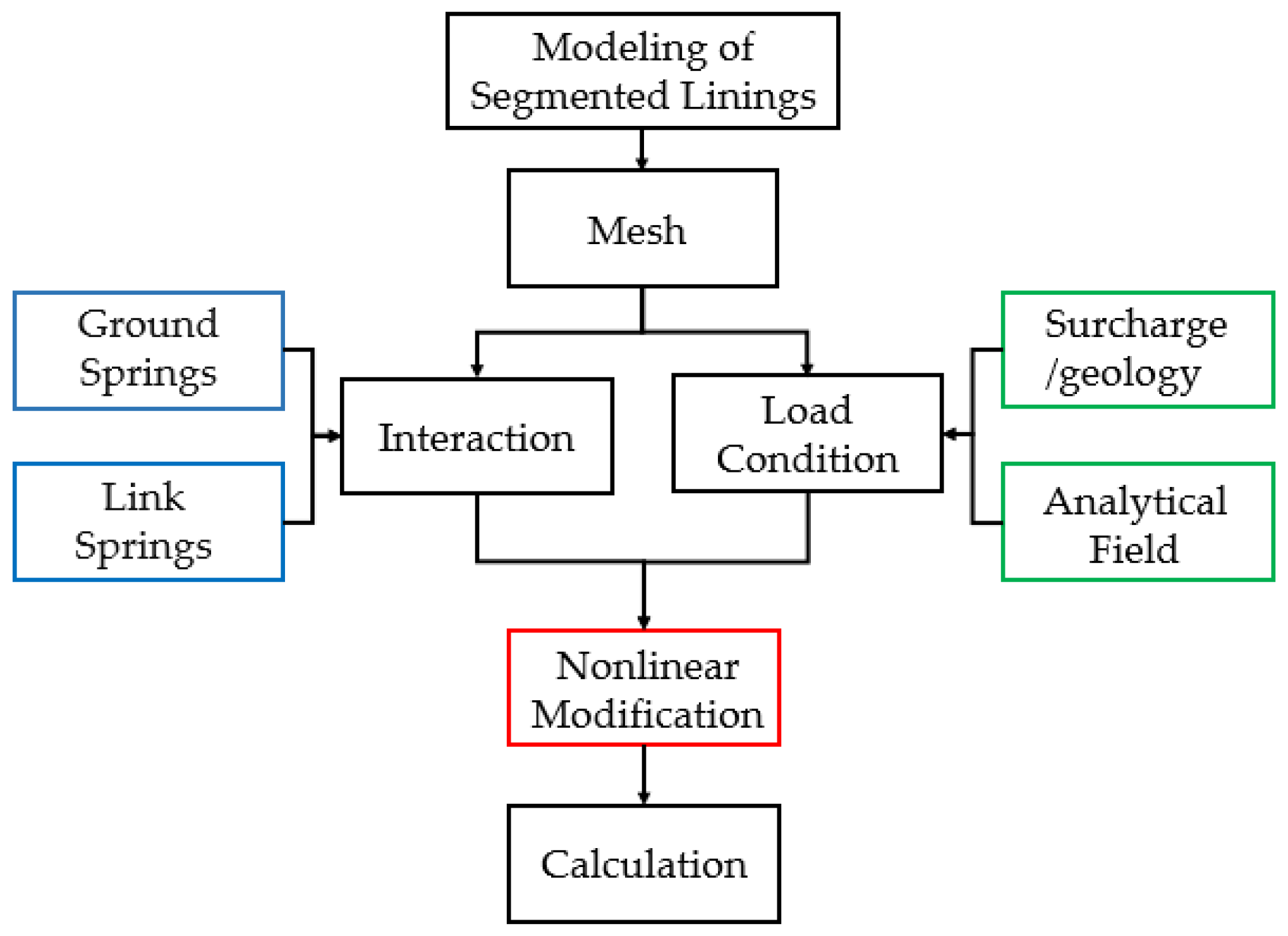
2. Modelling Strategy

The development and utilization of underground space in Shanghai mainly focuses on the range below the surface within 50 m. Within this range, the strata are mainly composed of soft cohesive soil and saturated sandy soil, with a high groundwater level. A typical geological cross-section of the Shanghai Metro can be seen in Figure 1. The subway lines in Shanghai are complex and intersecting, and some have been under construction for a long time. Therefore, the maintenance of lining structures is crucial for operation. Many scholars have conducted relevant research on the performance of Shanghai tunnel segments.
Where r is the density of the soil, C is the cohesion, R o is the outer radius, and R i is the inner radius, H is the distance from the top of the tunnel to the ground.
Taking the tunnel structure of Shanghai Metro Line 5 as an example, this paper uses numerical simulation methods to calculate the structural response of shield tunnel segments in the Shanghai Metro. The basic assumptions of the numerical simulation in this paper are as follows:
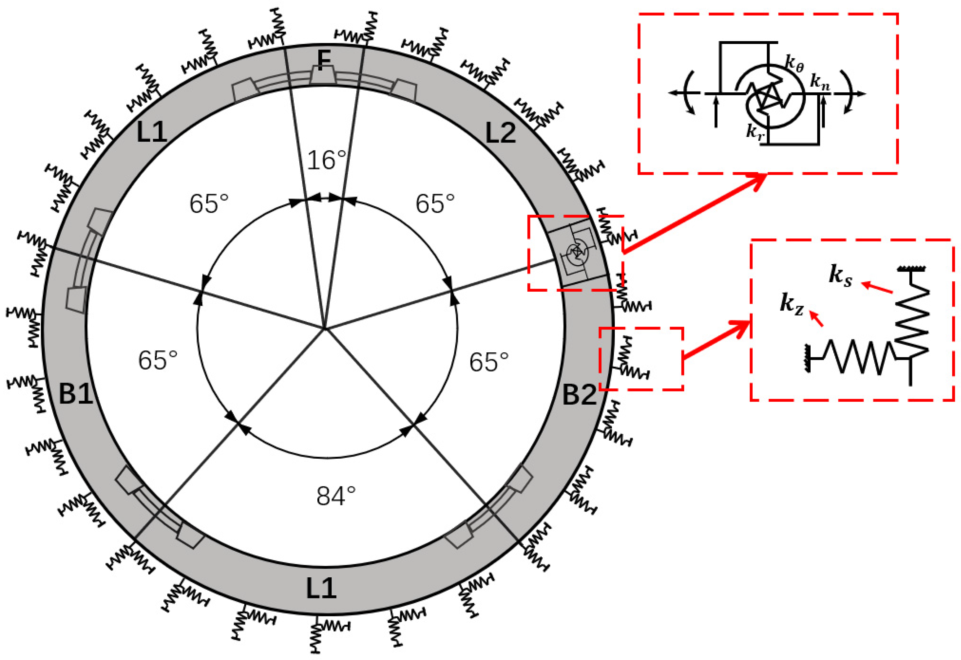
  • Based on the Winkler method, radial ground contact springs k s and tangential ground contact springs k z are introduced to simulate the contact between the segment structure and the strata (see Figure 2);
  • According to the mechanical properties of the soil, the tensile-compressive springs can only withstand compression but not tension, i.e., k t = 0 ;
  • At the joints of the segments, three sets of mechanical springs with discontinuous deformations are used to simulate tensile-compressive springs ( k n ), shear springs ( k r ), and rotational springs ( k ϴ ); it is assumed that the node displacements at the joint positions of adjacent segments are different in the calculation (see Figure 2); among them, the influence of tensile-compressive springs and shear springs on the internal forces and deformations of the structure is relatively small [23]; this paper only considers the influence of rotational springs on the structure, and sets the tensile-compressive springs and shear springs to relatively large values;
  • In the calculation of the segment structure, we focus more on the bending behavior of the structure, ignoring shear deformations, and use the Euler–Bernoulli beam model to simulate the segment structure.
The outer diameter of the shield tunnel lining structure in the Shanghai Metro is 6.20 m, and the inner diameter is 5.50 m. The width of the ring is 1.20 m, and the thickness is 0.35 m, cast with C50 concrete. Each ring consists of 1 key segment (F), 2 adjacent segments (L1 and L2), 2 standard segments, and 1 counter key segment (D), and is symmetric about the y-axis. The cross-section of the lining structure is shown in Figure 2.
The burial depth of Shanghai Metro tunnels ranges from 10 m to 30 m. One common geological formation is soft clay, which is typically moist with high water content and low strength. The lateral pressure coefficient for cohesive soil usually ranges from 0.5 to 0.7, while the soil resistance typically ranges from 5000 k N / m 3 to 15,000 k N / m 3 [23]. Assuming a tunnel depth of 14 m, the corresponding geological parameters are shown in Table 1.
The main load distribution of the shield tunnel is shown schematically in Figure 3.
In the manner depicted in Figure 3, P 0 represents the ground surcharge, P 1 stands for the vertical overburden earth pressure at the tunnel crown, P 2 stands for the reaction of vertical overburden earth pressure at the tunnel invert, P 3 stands for the lateral earth pressure at the tunnel crown, P 4 stands for the lateral earth pressure at the tunnel invert, P g represents the self-weight reaction of the structure, and R is the diameter of the tunnel segment. Assuming that the geological structure of the tunnel’s formation is uniform, the lateral load applied to the structure is symmetric about the y-axis.
The structural loads are calculated by the following equations:
P 1 = P 0 + ρ s H
P 2 = P 0 + ρ s H + P g
P 3 = K 0 P 0 + ρ s H
P 4 = 2 K 0 R ρ s
p g = π ρ c g h
where K 0 represents the coefficient of lateral earth pressure, determined by soil properties and empirical data, ρ s denotes the density of the soil, ρ c represents the density of the lining structure, h is the depth of the tunnel, and g is the acceleration due to gravity.
The process flow in the finite element method (FEM) can be seen in Figure 4, and Table 2 lists the parameters in the FEM simulation.
This paper utilizes the commercial software ABAQUS 2022 for numerical simulation. Block modeling facilitates the implementation of discontinuous effects at joints. The interaction between the lining structure and surrounding soil is simulated using ground springs, while adjacent nodes at the joints are connected by dimensionless connecting springs. Load conditions are determined by geological conditions and ground overloading, as shown in Figure 3. Lateral pressure is applied to the lining structure through an analytical field. Nonlinear effects of ground springs and connecting springs can be modified in the generated files, enabling the computation of internal forces and the deformation of the structure.
In FEM simulation, the stiffness of the tunnel structure is simulated by several Winkler ground springs. The stiffness of a single Winkler spring unit is calculated by the following equation:
E = E s 1 + ν s R
k s n = E 2 π R b n
where E s is the Young’s modulus of the soil, E is the stiffness of the surrounding soil, ν s is the Poisson’s ratio of the soil, R is the radius where the center of mass of the tunnel lining is located, k s n is the radial compressive stiffness of a single ground spring, n is the number of nodes in the finite element division, and b is the lining thickness.
Oriol [30] suggests that the stiffness of the circumferential springs can be taken as 1/3 of the radial springs based on experimental results, which has been used in numerical simulation [20].
k z n = k s n 3
Here, k z n is the circumferential stiffness of a single ground spring.

3. Subgrade Reaction Coefficient and Lateral Pressure Coefficient

Based on Winkler’s assumption, the ground resistance is assumed to be distributed along the lining ring and radial direction. This interaction between the lining and the ground is represented by springs, with the ground resistance considered as the reaction force generated during deformation in the direction of the foundation of the tunnel lining. Elastic ground springs are utilized to simulate the interaction between the lining and the surrounding rock, with the stiffness value of these Winkler springs being highly correlated with the mechanical properties of the ground. This value significantly impacts the results of the lining structure calculation. Improving the accuracy of numerical simulation results involves determining the foundation resistance coefficient and lateral pressure coefficient of the strata. The former represents the reaction force of the soil against the length of the foundation, determining the axial and tangential stiffness of the Winkler spring, while the latter is an engineering parameter representing the pressure exerted by the soil on the sides of the structure, determining the lateral earth pressure on the lining.
In this section, numerical simulations are conducted based on the range of values for foundation resistance coefficients and lateral pressure coefficients applicable to the soft ground strata in Shanghai, as outlined in Table 1. Complete section geometric features are extracted from extensive point cloud data obtained through 3D laser scanning of the Shanghai tunnel. Sectional cross-sectional deformation data are obtained by denoising and fitting the point cloud data using Euclidean clustering and B-spline methods. The model’s validity is verified by down-sampling the structural deformation of the tunnel’s point cloud section and quantitatively analyzing the influence of the foundation reaction coefficient and lateral pressure coefficient on the numerical calculation results of the Shanghai tunnel.

3.1. Subgrade Reaction Coefficient

Assuming a lateral pressure coefficient of 0.7, and considering a ground surcharge P 0 of 20 k N / m 2 , the load applied on the lining is as shown in Table 2. The range of the subgrade reaction coefficient varies from approximately 5000 k N / m 3 to 15,000 k N / m 3 , based on Equations (6)–(8). The numerical calculation results of the lining structure are illustrated in Figure 5.
As shown in Figure 5, the dashed line represents the position of the joints. The bending moment experienced by the structure reaches minimum values at the bottom and top of the tunnel, and maximum values in the lateral direction. As the foundation reaction coefficient decreases, the absolute value of the bending moment tends to increase. The axial force reaches maximum values at the bottom and top of the tunnel and minimum values in the lateral direction. With a decreasing foundation reaction coefficient, the overall absolute value of the axial force increases, and there is a discontinuity in the axial force at the joint. The overall deformation of the structure exhibits an ellipsoidal shape, with minimum values at the top and bottom of the tunnel, and maximum values in the lateral direction. As the foundation reaction coefficient decreases, the absolute value of deformation increases, consistent with the bending moment deformation. The rotational deformation increases with a decreasing foundation reaction coefficient, and the joint angle increases. In Figure 5c, when the foundation reaction coefficient is 5000 k N / m 3 , the overall error is minimal, with the maximum error occurring at the 100° position, measuring 6.5 m m . The next highest error occurs at the crown of the tunnel, measuring 3.1 m m . This indicates that the model can effectively simulate the deformation of the operational tunnel lining structure to a certain extent. However, based on the Winkler method, the structural load is symmetric, which does not accurately represent the effect of uneven engineering loads on tunnel structures.

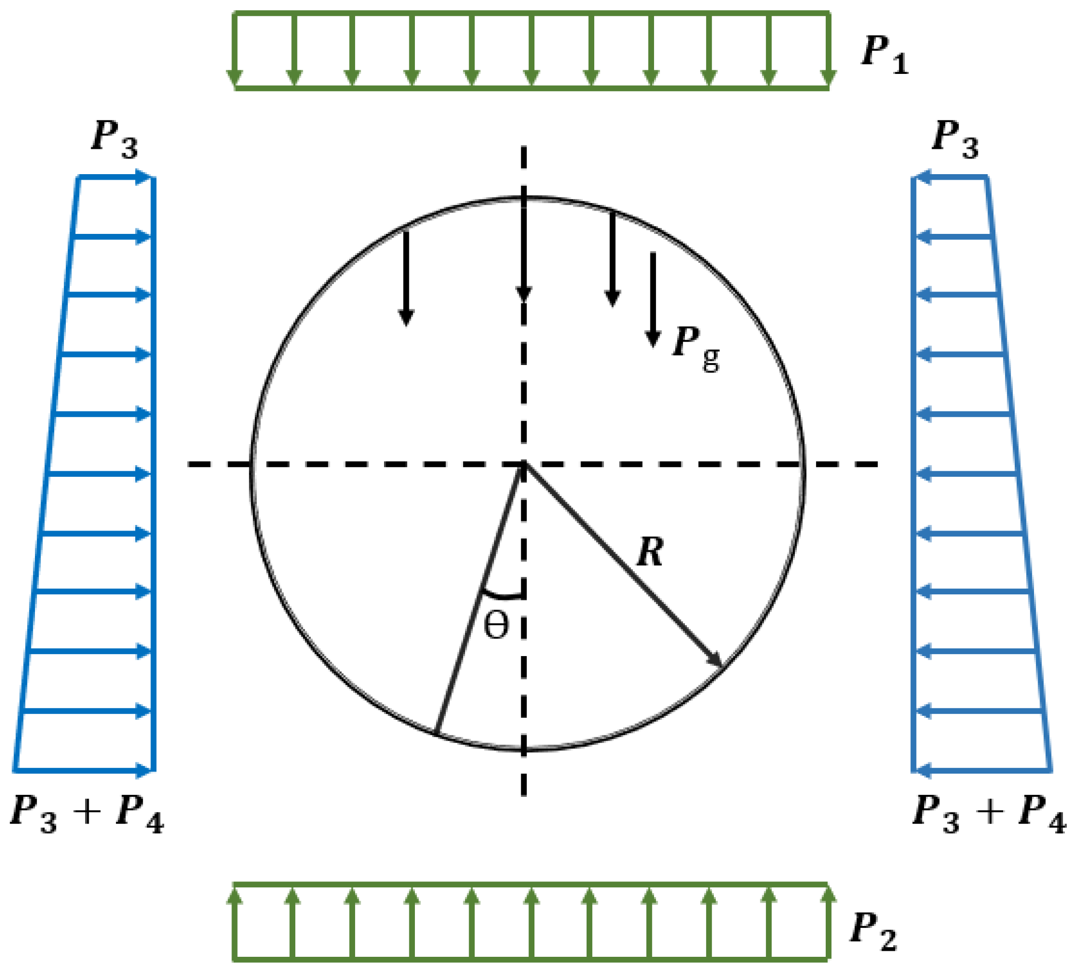
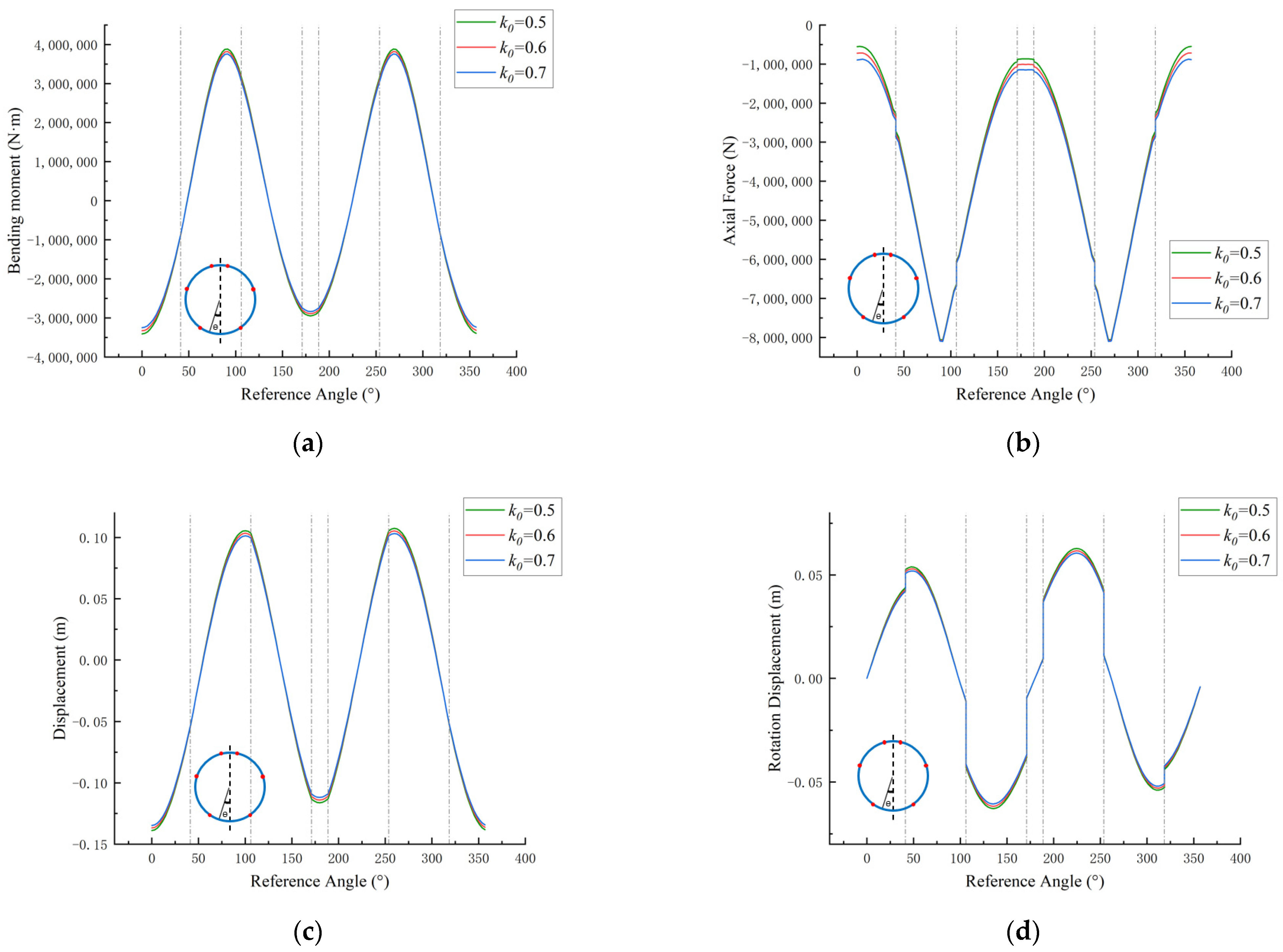
3.2. Lateral Pressure Coefficient

When the tunnel structure interacts with the soil, the soil exerts a force perpendicular to the side of the structure. The magnitude of the lateral earth pressure is influenced by factors such as soil properties, soil layer thickness, structural form, and depth. Under semi-infinite conditions, the lateral pressure is calculated by reducing the vertical effective pressure. The coefficient of lateral earth pressure is typically less than 1, and for the soft soil layers in Shanghai, it can range from 0.5 to 0.7. Assuming a soil resistance coefficient of 5000 k N / m 3 , the numerical calculation results of the lining structure are shown in Figure 6.
The influence of the lateral pressure coefficient affects the bending moments and deformations at the bottom, sidewalls, and top of the tunnel, as well as the axial forces at the top and bottom of the tunnel. As the lateral pressure coefficient decreases, the absolute values of bending moments and deformations increase at the critical points, while the absolute values of axial forces decrease at the bottom and top of the tunnel. The angle of rotation at joint B1-D slightly increases, with insignificant impact on the angles of rotation at other joints.

4. Analysis of Individual Joint Bending Stiffness

The bending stiffness of joints exhibits a highly nonlinear relationship with bending moments and axial forces. Currently, numerical simulation methods often employ direct and indirect approaches to study joint stiffness. Japanese JSCE has introduced an “η-ξ method”, determined by the efficiency of bending stiffness reduction η (where η < 1) and the increase rate of bending moments, denoted as ξ; when considering the entire ring as a uniformly stiff ring, the reduction of joint bending stiffness is evaluated as a reduction in the overall bending stiffness of the ring. Therefore, the stiffness of the lining is appropriately reduced during calculations, using the reduced stiffness η E I instead of the overall stiffness EI of the homogeneous ring segments. On the other hand, since lining joints have some hinge-like functionality, it can be assumed that not all bending moments are transmitted through the lining joints; instead, a portion of them is transmitted to adjacent lining rings connected by discontinuities. Hence, in the calculated internal forces of the cross-section, an increase or decrease factor ξ is considered for bending moments. The designed bending moment on the lining’s main cross-section is (1 + ξ) M, while the designed bending moment on the joint is (1 − ξ) M, where ξ represents the ratio of the bending moment transmitted to the neighboring ring to the calculated bending moment M.
However, determining the efficiency factor η and the increase rate ξ of bending moments for ring segment bending stiffness has always been a challenge. The direct approach involves simulating the mechanical effects of joints by introducing discontinuous springs for tension compression, shear, and rotation, which undoubtedly reduces computational efficiency but yields better results. In this section, by introducing discontinuous springs at the joints and not discussing the nonlinear effects at the joints, four sets of combinations of bending stiffness are taken to discuss the influence of a single joint’s reduction in bending stiffness on the structural calculation results. The B1-D joint, B1-L1 joint, and L1-F joint are considered, as shown in Figure 2, with bending stiffness values of 1000 k N / m 3 , 5000 k N / m 3 , 10,000 k N / m 3 , and 15,000 k N / m 3 .
As shown in Figure 7, Figure 8 and Figure 9, the blue and red lines represent the positions of the joints, and the red line indicates the joint where the bending stiffness is adjusted. The red reference line along the axial direction denotes zero. When the joint experiences negative bending moments, a decrease in joint bending stiffness leads to an increase in nearby bending moments. The absolute value of the axial force tends to decrease as the bending stiffness of the L1-B1 and F-L1 joints decreases, while the change in the axial force with the bending stiffness at B1-D joint is not significant. Conversely, when the joint bending moment is positive, a decrease in joint bending stiffness results in a decrease in nearby bending moments. The opening of the joint increases rapidly as the joint bending stiffness decreases, affecting neighboring joints through the transfer of forces along the beams (depending on the joint’s position). Specifically, joints B1-D and F-L1 experience negative bending moments, causing the joints to open outward. At joint L1-B1, the bending moment is positive and relatively large, causing the joint to open inward with a significant angle. The reduction in the bending stiffness of a particular joint affects a certain range of the ring segments, gradually diminishing in influence with increasing distance from the joint. The influence is highly dependent on the bending moment’s sign and the joint’s position. This provides insights for the numerical simulation and analytical calculation of joints in indirect methods. It is worth noting that the highly nonlinear nature of bolts and ring structures leads to variations in joint bending stiffness, which differ under positive and negative bending moments, with joints often exhibiting higher stiffness under positive bending moments than under negative bending moments [1].

5. Conclusions

This article proposes a numerical simulation method based on the beam–spring discontinuous model, which considers the discontinuity at the joints of segmental linings and the nonlinear characteristics of the surrounding soil subjected to compression but not tension. By studying the soft soil layers and lining conditions of Shanghai Metro Line 5, numerical simulations are conducted for multiple sets of lateral pressure coefficients and soil resistance coefficients. The results are compared with the deformation of three-dimensional laser-scanned point cloud cross-sections, validating the effectiveness of the model. Additionally, the impact of reducing the bending stiffness of individual joints on the overall lining structure is investigated, exploring how the size and location of joint bending stiffness affect internal forces and deformations within the entire ring.
(1)
Based on the conditions of the soft soil layers in Shanghai, numerical simulation results show that the tunnel experiences negative bending moments at the crown and bottom, while positive bending moments occur along the sides. The axial force is negative, peaking at the tunnel sidewalls. Tunnel deformation takes on an elliptical shape. Additionally, under the influence of bending moments, joints exhibit angular distortion.
(2)
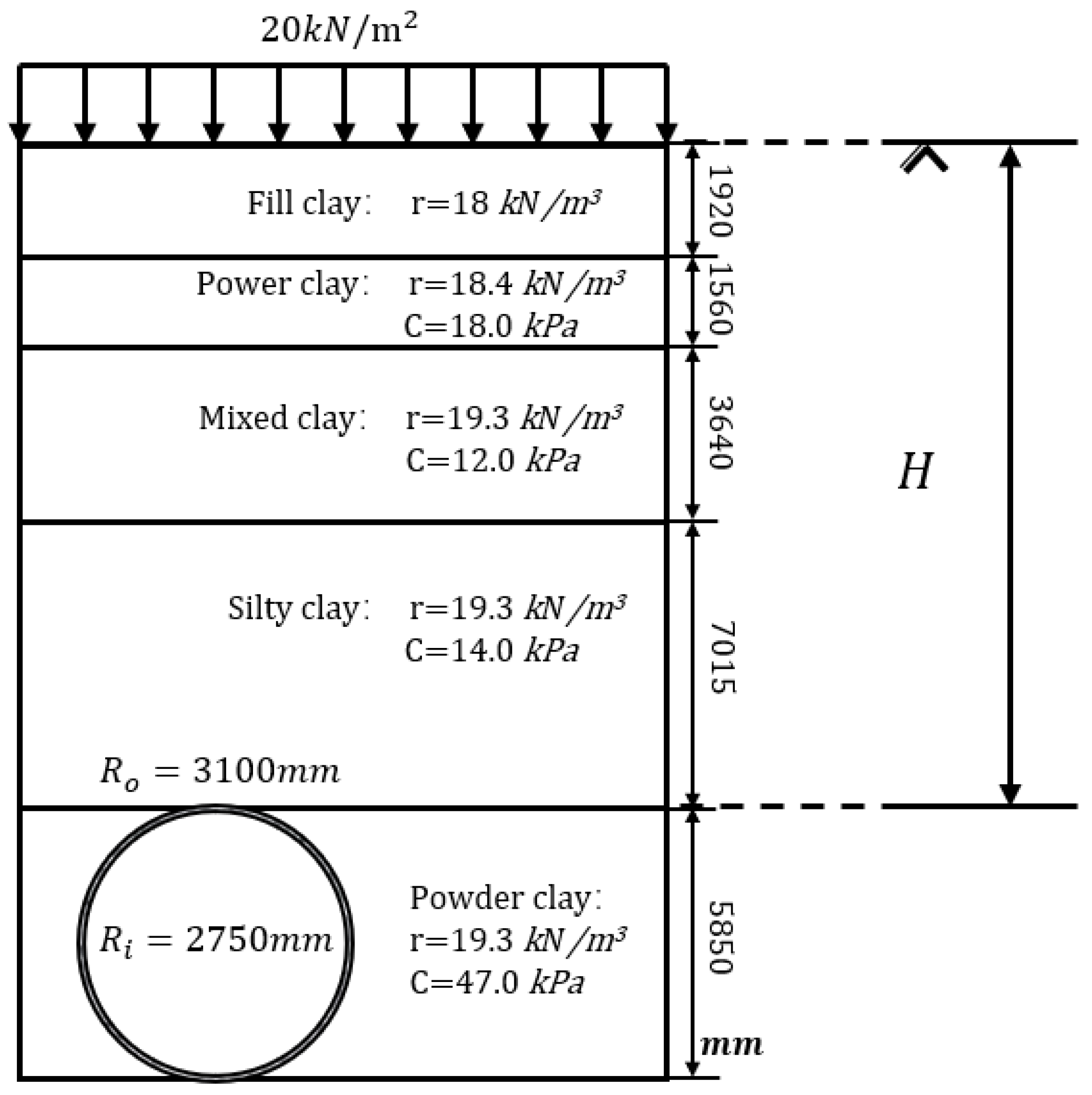
When the subgrade reaction coefficient decreases, the absolute values of bending moments, axial forces, and deformations at the tunnel crown and bottom generally increase. A discontinuity in axial forces occurs at the joints. The effectiveness of the model was verified by comparing the deformation of 3D laser scanning point cloud sections. When the foundation resistance coefficient is 5000 k N / m 3 , the deformation is closer to the actual values, with the maximum error occurring at the left sidewall of the tunnel (6.5 mm), followed by the tunnel crown (3.1 mm). When the lateral pressure coefficient decreases, the absolute values of bending moments and deformations at the tunnel crown, bottom, and sidewalls generally increase, while the absolute values of axial forces at the top and bottom decrease.
(3)
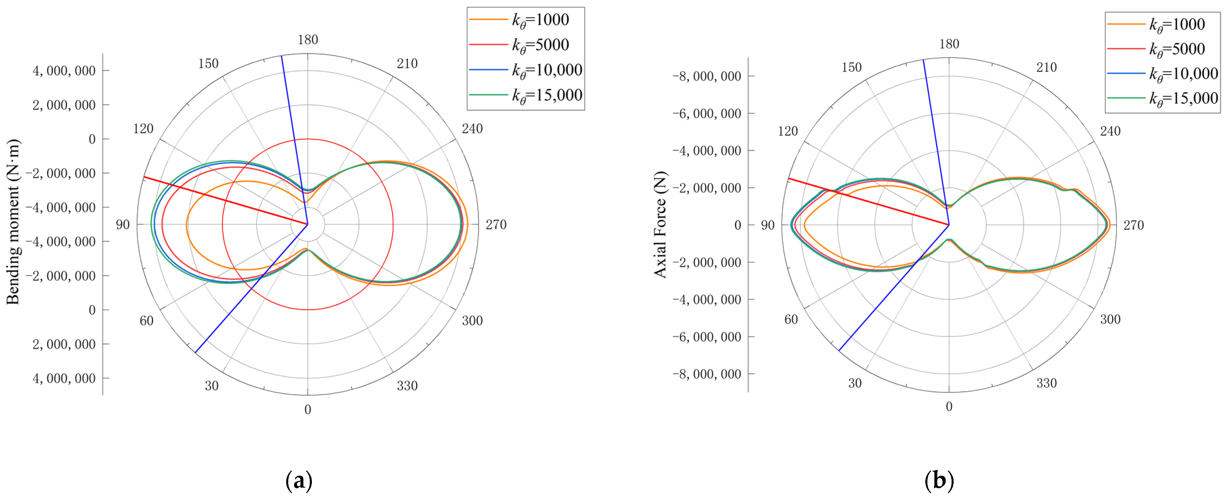
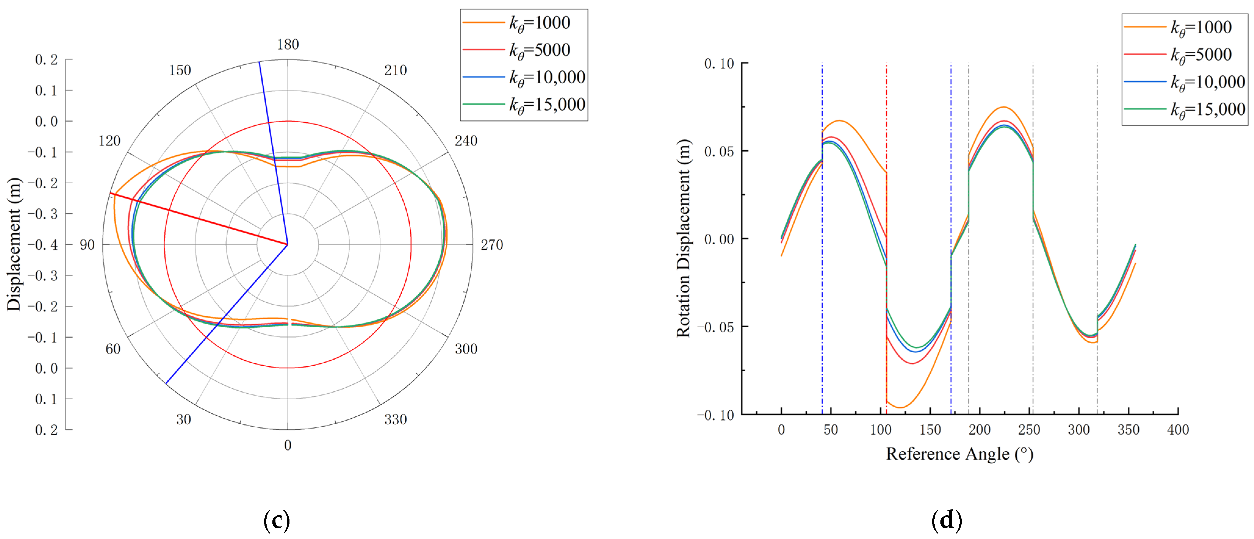
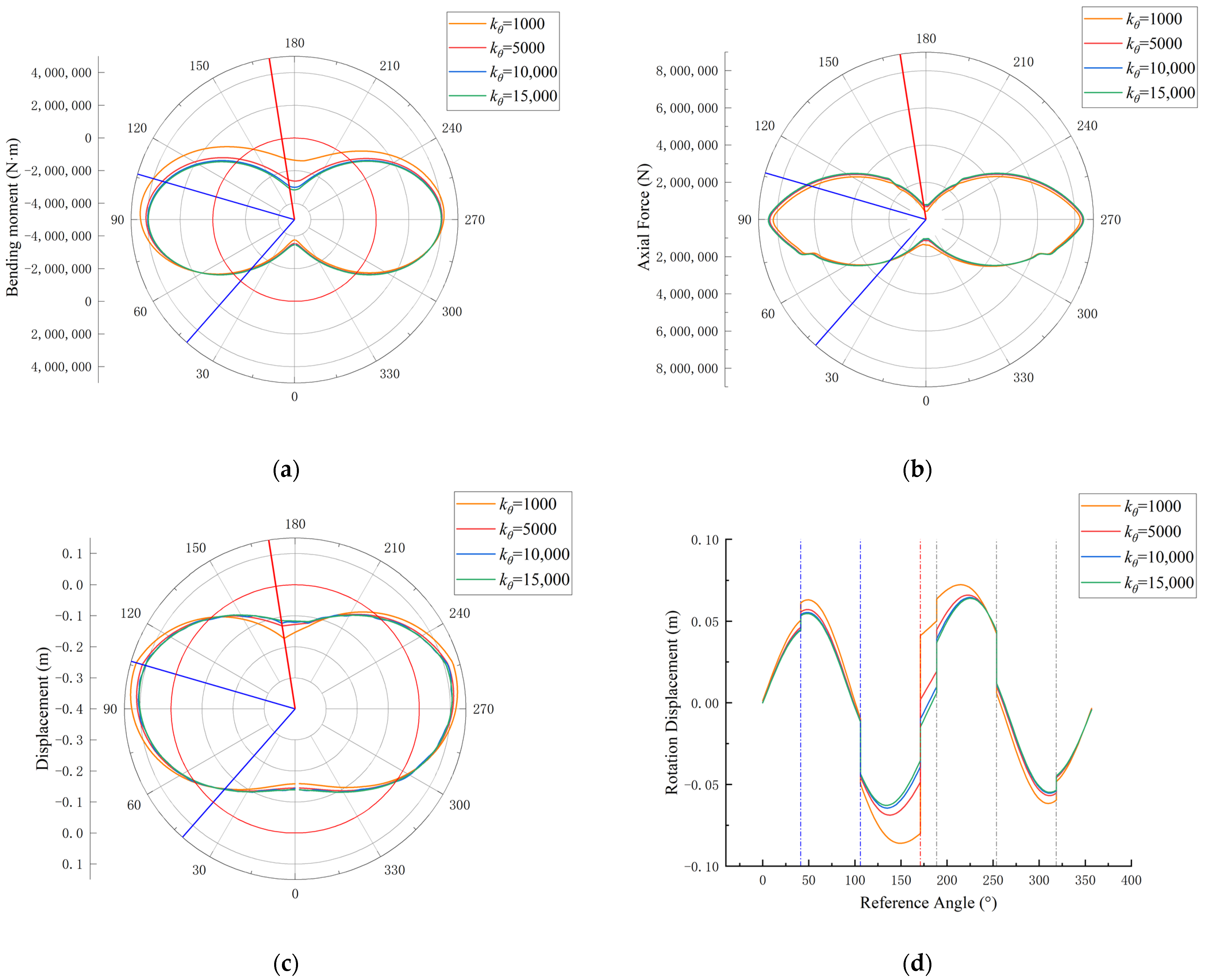
The bending stiffness of individual joints of single-ring segments in soft soil layers was reduced. When the bending moment at the joint is negative, a decrease in joint bending stiffness leads to an increase in nearby bending moments, while a decrease in joint bending stiffness leads to a decrease in nearby bending moments when the bending moment at the joint is positive. As the bending stiffness decreases, the joint opening angle increases, affecting the entire ring through beam transfer. The extent and magnitude of this effect depend on the bending moment at the joint and the joint’s position, providing reference for the calculation of bending moments in traditional indirect methods for ring segments and joints.
Currently, numerical simulation of segmental lining structures is often compared with analytical calculations and full-scale experimental results to validate model effectiveness. Three-dimensional laser scanning can effectively monitor the structural deformations of tunnels in later stages, and the model proposed in this study offers new insights for the health monitoring of tunnel linings.

Author Contributions

Methodology, X.H., X.X. and H.Y.; investigation, X.H, H.Y. and X.X.; resources, H.Y. and X.X.; data curation, H.Y. and X.X.; writing—original draft preparation, X.H. and X.X.; writing—review and editing, X.H., X.X. and H.Y.; project administration, H.Y. and X.X.; funding acquisition, H.Y. and X.X. All authors have read and agreed to the published version of the manuscript.

Funding

This research was funded by the National Natural Science Foundation of China (No: 52308323, U1934209, 52090084), Natural Science Foundation of Jiangsu Province, China (BK20220502) and Suzhou Innovation and Entrepreneurship Leading Talent Plan (No. ZXL2022488).

Data Availability Statement

The data provided in this work are available from the corresponding author.

Conflicts of Interest

The authors declare no conflicts of interest.

References

  1. Wang, F.; Shi, J.; Huang, H.; Zhang, D. Modified analytical solution of shield tunnel lining considering nonlinear bending stiffness of longitudinal joint. Tunn. Undergr. Space Technol. 2020, 106, 103625. [Google Scholar] [CrossRef]
  2. Moreno-Martinez, J.Y.; Galvan, A.; Pena, F.; Carpio, F. Practical Model Proposed for the Structural Analysis of Segmental Tunnels. Appl. Sci. 2020, 10, 8514. [Google Scholar] [CrossRef]
  3. Ngoc-Anh, D.; Dias, D.; Oreste, P.; Djeran-Maigre, I. Three-dimensional numerical simulation for mechanized tunnelling in soft ground: The influence of the joint pattern. Acta Geotech. 2014, 9, 673–694. [Google Scholar] [CrossRef]
  4. Wu, Y.; Ding, W.; Li, S.; Qiao, Y. Effect of oblique bolt arrangement on flexural behavior of segmental joint for shield tunnel. Tunn. Undergr. Space Technol. 2023, 135, 105043. [Google Scholar] [CrossRef]
  5. Zhong, X.; Zhu, W.; Huang, Z.; Han, Y. Effect of joint structure on joint stiffness for shield tunnel lining. Tunn. Undergr. Space Technol. 2006, 21, 407–408. [Google Scholar]
  6. Gong, C.; Ding, W.; Mosalam, K.M.; Gunay, S.; Soga, K. Comparison of the structural behavior of reinforced concrete and steel fiber reinforced concrete tunnel segmental joints. Tunn. Undergr. Space Technol. 2017, 68, 38–57. [Google Scholar] [CrossRef]
  7. Zhang, D.-M.; Zhang, B.-L.; Luo, T.-L.; Zhang, D.-M.; Li, B.-J. Full-scale testing and numerical modelling of segmental-joint performance with corroded bolt. Tunn. Undergr. Space Technol. 2022, 119, 104260. [Google Scholar] [CrossRef]
  8. Guo, W.; Feng, K.; Zhou, Y.; Yang, W.; Lu, X.; Xiao, M.; He, C. Full-scale test and numerical modeling on deformation and damage behavior of segmental joints under ultimate compression-bending load. Eng. Struct. 2023, 279, 115648. [Google Scholar] [CrossRef]
  9. Li, Z.; Yue, X.; Wu, G. Calculation and Analysis of Pipe Joint Settlement Control in Large Back Silting Immersed Tube Tunnel. Sustainability 2023, 15, 7446. [Google Scholar] [CrossRef]
  10. Oreste, P.P. A numerical approach to the hyperstatic reaction method for the dimensioning of tunnel supports. Tunn. Undergr. Space Technol. 2007, 22, 185–205. [Google Scholar] [CrossRef]
  11. Do, N.A.; Dias, D.; Oreste, P.; Djeran-Maigre, I. A new numerical approach to the hyperstatic reaction method for segmental tunnel linings. Int. J. Numer. Anal. Methods Geomech. 2014, 38, 1617–1632. [Google Scholar] [CrossRef]
  12. Do, N.A.; Dias, D.; Oreste, P.; Djeran-Maigre, I. 2D numerical investigation of segmental tunnel lining behavior. Tunn. Undergr. Space Technol. 2013, 37, 115–127. [Google Scholar] [CrossRef]
  13. Chen, Q.J.; Wang, J.C.; Huang, W.M.; Yang, Z.X.; Xu, R.Q. Analytical solution for a jointed shield tunnel lining reinforced by secondary linings. Int. J. Mech. Sci. 2020, 185, 105813. [Google Scholar] [CrossRef]
  14. Wang, J.; Huang, W.; Xu, R.; Yang, Z.; Xu, R. Analytical approach for circular-jointed shield tunnel lining based on the state space method. Int. J. Numer. Anal. Methods Geomech. 2020, 44, 575–595. [Google Scholar] [CrossRef]
  15. Chen, Z.P.; Wang, J.C.; Xu, R.Q.; Yang, Z.X.; Gong, X.N. Dynamic analysis of segmental linings of shield tunnels using a state space method and its application in physical test interpretation. Tunn. Undergr. Space Technol. 2023, 137, 105103. [Google Scholar] [CrossRef]
  16. Zhou, L.; Zhu, H.; Yan, Z.; Shen, Y.; Guan, L.; Wen, Z.; Li, Y. Experimental study on mechanical behaviors of segmental joints with ductile-iron joint panels for deep-buried shield tunnels bearing high inner water pressure. Tunn. Undergr. Space Technol. 2022, 127, 104590. [Google Scholar] [CrossRef]
  17. Huang, W.M.; Wang, J.C.; Yang, Z.X.; Xu, R.Q. Analytical model for segmental tunnel lining with nonlinear joints. Tunn. Undergr. Space Technol. 2021, 114, 103994. [Google Scholar] [CrossRef]
  18. Liu, X.; Liu, Y.; Jiang, Z.; Wang, J.; Mang, H.A. Numerical investigation of the mechanical behavior of segmental tunnel linings reinforced by a steel plate—Concrete composite structure. Eng. Struct. 2023, 276, 115350. [Google Scholar] [CrossRef]
  19. Zhang, D.M.; Phoon, K.K.; Hu, Q.F.; Huang, H.W. Nonlinear subgrade reaction solution for circular tunnel lining design based on mobilized strength of undrained clay. Can. Geotech. J. 2018, 55, 155–170. [Google Scholar] [CrossRef]
  20. Yuan, Q.; Liang, F.; Wang, R. Analytical approach for segmental tunnels considering nonlinear longitudinal joints in soft soils. Transp. Geotech. 2022, 36, 100807. [Google Scholar] [CrossRef]
  21. Sugimoto, M.; Chen, J.; Sramoon, A. Frame structure analysis model of tunnel lining using nonlinear ground reaction curve. Tunn. Undergr. Space Technol. 2019, 94, 103135. [Google Scholar] [CrossRef]
  22. Anh The, P.; Sugimoto, M. The Effects of Tangential Ground-Lining Interaction on Segmental Lining Behavior Using the Beam-Spring Model. Appl. Sci. 2020, 10, 1084. [Google Scholar] [CrossRef]
  23. Lee, K.M.; Hou, X.Y.; Ge, X.W.; Tang, Y. An analytical solution for a jointed shield-driven tunnel lining. Int. J. Numer. Anal. Methods Geomech. 2001, 25, 365–390. [Google Scholar] [CrossRef]
  24. Li, X.; Yan, Z.; Wang, Z.; Zhu, H. A progressive model to simulate the full mechanical behavior of concrete segmental lining longitudinal joints. Eng. Struct. 2015, 93, 97–113. [Google Scholar] [CrossRef]
  25. Zhai, W.; Zhang, D.; Huang, H.; Chapman, D. Numerical investigation into the composite behaviour of over-deformed segmental tunnel linings strengthened by bonding steel plates. Soils Found. 2023, 63, 101335. [Google Scholar] [CrossRef]
  26. Yuan, Q.; Liang, F.; Fang, Y. Numerical simulation and simplified analytical model for the longitudinal joint bending stiffness of a tunnel considering axial force. Struct. Concr. 2021, 22, 3368–3384. [Google Scholar] [CrossRef]
  27. Xu, X.; Wang, Z.; Shi, P.; Liu, W.; Tang, Q.; Bao, X.; Chen, X.; Yang, H. Intelligent monitoring and residual analysis of tunnel point cloud data based on free-form approximation. Mech. Adv. Mater. Struct. 2023, 30, 1703–1712. [Google Scholar] [CrossRef]
  28. Wang, Z.; Xu, X.; He, X.; Wei, X.; Yang, H. A Method for Convergent Deformation Analysis of a Shield Tunnel Incorporating B-Spline Fitting and ICP Alignment. Remote Sens. 2023, 15, 5112. [Google Scholar] [CrossRef]
  29. Wang, Z.; Shi, P.; Xu, X.; Xu, X.; Xie, F.; Yang, H. Automatic Identification and Intelligent Optimization of Tunnel-Free Curve Reconfiguration. Symmetry 2022, 14, 2505. [Google Scholar] [CrossRef]
  30. Arnau, O.; Molins, C. Experimental and analytical study of the structural response of segmental tunnel linings based on an in situ loading test. Part 2: Numerical simulation. Tunn. Undergr. Space Technol. 2011, 26, 778–788. [Google Scholar] [CrossRef]
Figure 1. A typical geological cross-section of the Shanghai Metro.
Symmetry 16 00650 g001
Figure 2. The lining structure in Shanghai tunnels and assumptions regarding connecting springs.
Symmetry 16 00650 g002
Figure 3. The earth pressure applied on the tunnel lining under semi-infinite conditions with consideration of ground surcharge.
Symmetry 16 00650 g003
Figure 4. Flowchart of the FEM process considering joint discontinuity and nonlinear ground springs.
Symmetry 16 00650 g004
Figure 5. The illustration of results with respect to the reference angle when the subgrade reaction coefficient is altered. (a) Bending moment; (b) axial force; (c) radial deformation; (d) rotational deformation.
Symmetry 16 00650 g005
Figure 6. The illustration of results with respect to the reference angle when lateral pressure coefficient is altered. (a) Bending moment; (b) axial force; (c) radial deformation; (d) rotational deformation.
Symmetry 16 00650 g006
Figure 7. The illustration of results with respect to the reference angle when joint B1-D is altered. (a) Bending moments; (b) axial force; (c) radial deformations, and (d) rotational deformations.
Symmetry 16 00650 g007
Figure 8. The illustration of results with respect to the reference angle when joint L1-B1 is altered. (a) Bending moments; (b) axial force; (c) radial deformations, and (d) rotational deformations.
Symmetry 16 00650 g008aSymmetry 16 00650 g008b
Figure 9. The illustration of results with respect to the reference angle when joint F-L1 is altered. (a) Bending moments; (b) axial force; (c) radial deformations, and (d) rotational deformations.
Symmetry 16 00650 g009
Table 1. Classic geological parameters of Shanghai.
Symbol Properties UnitValue
Material parameters of soil ρ s Density of soil k N / m 3 18
K s Subgrade reaction coefficient(compression) k N / m 3 3000~15,000
K t Subgrade reaction coefficient(tension) k N / m 3 0
K 0 Coefficient of lateral pressure 0.5~0.7
ν s Poisson s ratio of soil 0.35
E s Young’s modulus of soil k P a 1.68 × 10⁴
H Embedded depth m 14
Table 2. Basic parameters for lining structure calculation in FEM.
Parameter ClassificationSymbolProperties UnitValue
Geometrical parameters of tunnel lining R Radius m 2.925
b Width m 1
h Thickness m 0.35
Material parameters of tunnel lining ρ c Density of segment k N / m 3 2.5
E c Young’s modulus of segment k P a 3.45 × 10⁷
ν c Poisson’s ratio of segment/0.2
Stiffness parameters of soil spring k s n Radial k P a / m 450
k z n Tangential k P a / m 150
Stiffness parameters of joints k n Compress spring k N / m 1 × 10⁷
k r Shear spring k N / m 1 × 10¹⁰
k ϴ Moment spring k N · m / r a d 1.54 × 10⁵
Load P 0 ground overload k P a / m 20
P g Self weight of the tunnel lining k P a / m 317
P 1 Vertical overburden earth pressure at the tunnel crown k P a / m 270
P 2 Vertical overburden earth pressure at the tunnel invert k P a / m 317
P 3 Lateral earth pressure at the tunnel crown k P a / m 175
P 4 Additional earth pressure at the tunnel invert k P a / m 245
Disclaimer/Publisher’s Note: The statements, opinions and data contained in all publications are solely those of the individual author(s) and contributor(s) and not of MDPI and/or the editor(s). MDPI and/or the editor(s) disclaim responsibility for any injury to people or property resulting from any ideas, methods, instructions or products referred to in the content.

