Abstract
Although robots have been widely used in a variety of fields, the idea of enabling them to perform multiple tasks in the same way that humans do remains a difficulty. To solve this, we investigate the learning from demonstration (LFD) system with our independently designed symmetrical humanoid dual-arm robot. We present a novel action feature matching algorithm. This algorithm accurately transforms human demonstration data into task models that robots can directly execute, considerably improving LFD’s generalization capabilities. In our studies, we used motion capture cameras to capture human demonstration actions, which included combinations of simple actions (the action layer) and a succession of complicated operational tasks (the task layer). For the action layer data, we employed Gaussian mixture models (GMM) for processing and constructing an action primitive library. As for the task layer data, we created a “keyframe” segmentation method to transform this data into a series of action primitives and build another action primitive library. Guided by our algorithm, the robot successfully imitated complex human tasks. Results show its excellent task learning and execution, providing an effective solution for robots to learn from human demonstrations and significantly advancing robot technology.
1. Introduction
In recent years, robotics and artificial intelligence have developed rapidly, and robots now play an indispensable role in factory workshops or daily life [1,2,3]. Traditional industrial robotic arms are designed for heavy loads and huge operating spaces. Therefore, they are typically quite large and unsuitable for human–robot collaborative service work. To ensure the safety of human–robot interaction and workspace sharing, we adopt the self-designed and built dual-arm robot with a bionic dual-arm structure that has six degrees of freedom on both the left and right arms. The robot’s configuration and D-H parameters have been slightly enhanced when compared with standard industrial robotic arms, and it can replicate most of the limb movements demonstrated by human arms. Combined with the Mecanum wheel mobile chassis at the bottom, the robot can flexibly achieve various forms of planar motion. The whole machine is based on ROS (robot operating system) for the development of the underlying control system, directly acquiring data from various sensors and controlling the robot to perform various mobile and operation tasks.
In most industrial applications, experts design code to enable robots to execute highly specialized and repetitive tasks. Programming by manual coding is time-consuming and expensive, and the results frequently lack generalizability. Currently, an effective substitute technique exists, i.e., LFD, also known as programming by demonstration (PBD) or imitation learning (IL). This method involves observing and recording human behavior with visual devices or external motion capture systems, and then enabling the robot to complete self-learning through artificial intelligence algorithms such as machine learning and reinforcement learning. LFD is easy to operate and has strong robustness. Based on these characteristics, robots can be taught and used by ordinary users, reducing the professional requirement for computer programming. With the help of LFD, robots can act as safer, more trustworthy, and more practical collaborators.
This study proposes an action feature matching algorithm and a motion segmentation method based on “key frames”. According to the symmetry principle, the action feature matching algorithm can accurately match the human demonstration data with the action primitive and represent it as the task model that the robot can execute. Using the motion segmentation method based on “key frames”, a complex operational task can be reasonably segmented into action clips. Based on this, we have developed an efficient LFD system for a humanoid dual-arm robot. The humanoid dual-arm robot has symmetry in structure design, which ensures the symmetrical design of the length and joint position of the robot’s arms. Symmetry is also guaranteed in the arrangement of sensors for humanoid dual-arm robots. In addition to functional symmetry, through symmetrical appearance design, the robot looks more in line with human aesthetics and increases affinity. Subsequently, we conducted two experiments to demonstrate that this humanoid dual-arm robot demonstration learning system can effectively perform various tasks, including but not limited to complex actions such as grasping and manipulation. This will provide strong support for the application of robots in industries, services, and other fields.
2. Related Work
In complex robotic systems, the manipulation tasks that robots face are difficult to express using analytical formulas. And traditional control theory can achieve satisfactory control results. LFD is one of the solutions, but the existing research still has certain limitations. Particularly when it comes to converting human demonstration actions into executable task models for robots, the current methods suffer from issues such as limited generalization capabilities or high implementation complexity.
In the past two decades, a variety of trajectory-based demonstration learning methods have been developed. These methods use various technical means to encode the teaching data of manipulation tasks and generate optimal reproduction trajectories [4,5,6]. Many studies on robotic demonstration learning focus on mapping and replicating human movements, with the goal of maximizing the imitation of precise motion trajectories associated with the set task [7,8,9,10,11,12]. For example, Fitzgerald et al. [13] used “kinesthetic teaching” to complete the QR code block rearrangement task, and Wu et al. [14] marked benchmark points on objects and the demonstrator’s arms and used visual motion tracking methods to record the trajectory of the benchmark points.
In order to interpret complex manipulation behaviors into a more mathematically tractable form [15,16,17,18,19,20,21,22,23,24], Calinon et al. [25] used GMM to establish a probabilistic representation of demonstration data and used Gaussian mixture regression (GMR) to generate smooth trajectory curves. Evrard et al. [26] proposed a probabilistic framework based on GMM and GMR for encoding and reconstructing robotic collaborative behavior.
Similar to GMM, Gaussian regression models can also generate a trajectory curve based on existing teaching data [27,28]. However, Gaussian regression models have a higher computational cost [29,30]. To address this issue, Schneider [31] proposed local Gaussian regression, which incorporates some custom constraints into the skill teaching data.
Combining artificial intelligence and experience sharing in LFD is also one of the research hotspots in this field in recent years [32,33,34,35,36,37,38,39]. Kehoe et al. [40] proposed an algorithm based on deep neural networks. The CLEARN project, led by MIT’s Julie A. Shah’s team [41], enables robots to learn multi-step operation tasks from a single demonstration, and multiple robots can share operation skills. Ebert et al. [42] proposed a reinforcement learning algorithm based on visual models that predicts the manipulation of previously unseen objects by the robotic arm.
3. Preliminaries
LFD is a robot self-learning method that extracts operational rules from observing human demonstrations of operation tasks and then reproduces the operational tasks using specific algorithms. LFD can be divided into three processes: behavior perception, behavior representation, and behavior reproduction [43], which correspond to the acquisition of teaching data, representation learning, and feature matching reproduction, respectively.
The operational behavior of humans performing tasks can be concretized as a collection of basic movements. Cohen et al. [44] proposed a skill learning method based on action templates: experimental state splitting (ESS). They constructed an action primitive library (such as move, rotate, twist, push, etc.), and the combination of these action primitives can present more complex actions. For example, the combination of “move to”, “contact”, and “push” expresses the action of “pushing”. By constructing finite-state automata based on action templates and composite actions, conditional transitions between different states can be achieved, thereby enabling the evolution of robotic operational skills from simple to complex.
4. Humanoid Dual-Arm Robot Demonstration Learning System
The method mentioned above is a commonly used template representation method in demonstration learning research, but it has limited adaptability to complex scenarios and weak generalization ability. Based on this method, this article improves the representation form of action primitives. We believe there is still room for improvement in the current action primitives. For example, the action primitive “move” can be further explained as “from S through M, arriving at E with a large (small) range of arcs (curves)”. This specific representation form transforms abstract task descriptions into easily processed mathematical equations, reducing ambiguity among elements in the process of teaching and skill learning.
This chapter introduces the underlying principles and research processes of the humanoid dual-arm robot demonstration learning system. Kinect2, as the robot’s visual sensor, can provide real-time feedback on the spatial location information of the manipulated object. The NOKOV-MARS series of motion capture devices, as collection equipment for human teaching data, can acquire both motion-level and task-level teaching trajectories.
At the motion level, GMMs are used to represent the trajectory data of taught actions, formalizing human behaviors as mathematical models, and forming a library of motion primitives. The robot is assisted to accomplish the critical step of breaking down a “task” into “actions” at the task level by using a “keyframe marker” method. Finally, we propose a new action feature matching algorithm to enable the robot to achieve behavioral understanding and reproduction.
4.1. The Framework of LFD System
Based on the existing hardware and software conditions, we propose a feasible LFD system framework (Figure 1). This framework is divided into three parts:
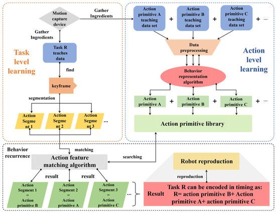
Figure 1.
LFD system framework diagram.
- (1)
- Motion Level Learning: Firstly, the composition members of the action primitive library are predefined, and most complex operation tasks can be represented by combining these members. Fourteen different types of preset action primitives (Table 1) can be represented by three spatial pose points each in this project. The primitive library can be dynamically added or subtracted based on needs at a later stage. Then, for each action primitive, human demonstration data is collected. The features of the demonstration data are extracted using behavioral representation algorithms to form the action primitive library for subsequent program retrieval and matching.
 Table 1. Action primitive library.
 - (2)
- Task Level Learning: Since an operating task is typically composed of multiple basic actions. One of the challenges in demonstration learning is figuring out how to segment complex tasks into reasonable action segments [45,46]. Currently, task segmentation algorithms rarely achieve satisfactory processing results. Therefore, this article proposes the following solution: introducing human decision making into task-level learning. The task data is segmented during the acquisition by manually inserting keyframe markers into the task, which means that the system just needs to represent the ordered combination of which action segments correspond to a task. The keyframe marker process is as follows: the demonstrator marks a keyframe by closing their middle finger from open to closed and then back to open. The demonstration process of keyframe markers is shown in Figure 2a, and Figure 2b shows the change in the angle between the middle finger and thumb.
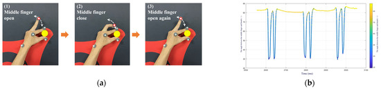 Figure 2. (a) Teaching demonstration process of the “keyframe marker” action primitive diagram; (b) angle between the middle finger and the thumb changes diagram.
 - (3)
- Behavior Reproduction: We propose a new action feature matching algorithm. This algorithm represents the input unknown action segment and the system’s action primitive library as three distinct spatial pose locations, with the goal of completing similarity matching between them. When a set of task data is input, the algorithm encodes the task into a combination of certain elements in the action primitive library in temporal order. Finally, these encoded data are input into the robot controller to realize behavior reproduction.
4.2. Creation of Action Primitives Library
In this study, we used the NOKOV-MARS series of motion capture devices to collect demonstration data on human arms, and we utilized Kinect2 along with the open-source find_object_2d function package to identify the manipulated object. To help assess the level of task accomplishment, real-time input on the category and geographical position of the object was given. It is worth mentioning that the detection accuracy of the NOKOV motion capture device can reach the sub-millimeter level, while Kinect2 provides millimeter-level precision in spatial position feedback. These high-precision data provide more accurate operation task information, enhancing the accuracy and stability of robot behavior reproduction.
As shown in Figure 3a, the demonstrator sported 18 retroreflective marker spots on their body during the teaching process to optimize the reflection of human body movement information in all arm dimensions. The experimental platform of the capture system is shown in Figure 3b, using a total of 8 NOKOV-MARS capture cameras. Researchers can conduct experiments within a range of 5–20 m2.
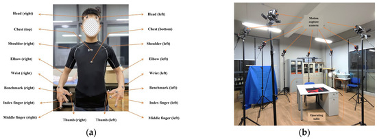
Figure 3.
(a) Light marker paste position diagram; (b) motion capture device layout diagram.
After considering the types of motion planning, end-effector range, end-effector trajectory, and robot state, the action primitive library of this topic is divided into 14 categories of components, as shown in Table 1. One by one, the demonstrator performs each reference motion form of the action primitives, and as each group of movements is completed, the motion capture system records the spatial position data of each marker point on the human body. After preprocessing such as deletion and denoising, the data are provided for subsequent algorithms for behavior representation.
For example, a single action primitive’s demonstration data collection is referred to as “small operation/straight line”. The action class primitives are the most important component of the demonstration learning system. Through their ordered combination, most operation tasks can be constructed, as shown in Figure 4. The term “small operation/straight line” defines the process of performing the end operation with small-range straight-line motion in Cartesian space. This type of action primitive is included in the composite action primitives since it also needs to work with the end effector’s gripping operation. The teaching process of this action primitive is shown in Figure 4, and the data visualization is shown in Figure 5.
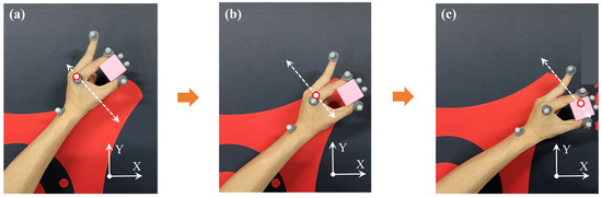
Figure 4.
Teaching demonstration process of the “small operation/straight line” action primitive (a) before operation pose; (b) in operation; (c) after operation pose.
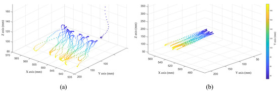
Figure 5.
End spatial position data of the “small operation/straight line” action primitive (a) original data; (b) after preprocessing data.
4.3. Action Layer of LFD
The purpose of the LFD at the action level is to enable the robot to understand the underlying characteristics of each action primitive. In this topic, we use GMM to complete this step. Firstly, we perform filtering on the demonstration trajectories. Then, we fit these trajectories with multiple Gaussian distributions using ellipses. Finally, we select the optimal path from the generalized trajectories as the reference standard for each action primitive. The implementation block diagram is shown in Figure 6. Following the action-level demonstration learning, we create an action primitive library in which the attributes of every primitive can be expressed as particular mathematical models. Next, we will introduce the research steps of demonstration learning at the action level in detail.
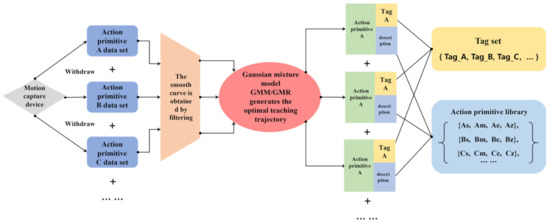
Figure 6.
Action layer demonstration learning implementation framework.
We use GMM to optimize the captured demonstration data. In this paper, the motion trajectory of the robotic arm’s end-effector in the base coordinate system is represented by a GMM made up of K SGM components. Assuming that there is a set of captured data , with N data points, let represent the probability distribution of and represent the prior probability of the kth Gaussian kernel. The following formula is used:
For each demonstration data point , the probability that it is generated by the kth Gaussian kernel is:
in is the value we want to estimate. Since each Gaussian kernel is a standard Gaussian distribution, it is easy to find the parameter value corresponding to the maximum likelihood.
The K-means clustering algorithm is utilized to obtain a more ideal initial value based on the maximum likelihood algorithm [47]. The mentioned iterative algorithm is then used to complete the parameter estimation. In addition, in this paper, the number of Gaussian kernels K is manually selected according to the actual fitting situation. After calculating the model parameters, further regression processing must be performed by using the GMR algorithm. Its function is to estimate the spatial position , corresponding to a time step sequence in trajectory X based on the GMM. The formulas for the expectation and variance of distribution are Formulas (8) and (9).
After derivation, we can obtain the optimal teaching trajectory point after generalization processing. Under the constraint of variance , it can generate a relatively smooth teaching trajectory. The regression function of the Gaussian mixture model is:
According to the GMR algorithm, further processing is performed on the teaching data. For example, the action primitive “large operation/arc” in the XOZ plane is shown in Figure 7.
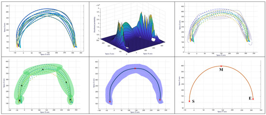
Figure 7.
GMM/GMR processing process of action primitive “big operation/arc” XOZ plane.
Since the trajectory points are three-dimensional data, they need to be processed from the perspectives of the XOZ, YOZ, and XOY planes, respectively. The detailed steps are as follows:
- (1)
- Select 10 sets of filtered teaching trajectory data.
- (2)
- Use the iterative method to estimate the parameters of the GMM. Once the model converges, it can be used to represent the teaching trajectory data. The GMM can be represented in space as a “mountain range” with K sections as ellipses. The height of the section corresponds to the probability of the teaching data distribution in this model.
- (3)
- Project the GMM onto the trajectory plane in the form of contour lines (Gaussian ellipses).
- (4)
- Perform further processing on the Gaussian ellipses to determine the center of the ellipses, thereby fitting the teaching data.
- (5)
- Use the GMR algorithm to generalize the model and obtain a smooth optimal teaching trajectory.
- (6)
- Reconstruct the action primitive by selecting the start point S, intermediate point M, and end point E from an optimal teaching trajectory, putting pose information, and then putting each point into the trajectory planning algorithm.
By repeating the above steps and fitting the teaching data of each action primitive in Table 1, we can establish a library of action primitives. Through the processing of the action-level demonstration learning model, each action primitive is ultimately represented by two key mathematical evaluation indicators: the straight-line distance from point S to point E and the radius of the circular arc . The former is used to distinguish the size of the operation range, and the latter is used to define the type of action planning (straight line or circular arc).
4.4. Task Layer of LFD
The purpose of LFD at the task level is to enable the robot to recognize complex human manipulation tasks, segment the tasks into more fundamental action primitives, and use a matching algorithm to find the most suitable action primitives from the library of action primitives to describe these action primitives. A task can then be represented in temporal sequence as a set of action primitives. Finally, the robot’s dual arms are used to replicate the human demonstration task in the form of a PVT instruction set. The implementation diagram of demonstration learning at the task level is shown in Figure 8.
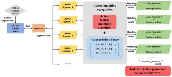
Figure 8.
Task layer implementation framework of LFD.
In this paper, the way to express tasks as action layers is to artificially add key frame actions to the teaching data at the task level. When the algorithm detects the existence of key frames, it performs segmentation operations at that position. Therefore, human subjective judgment is the main decision-making component during the expression stage of tasks. Through the overall execution framework of “human decision making as the mainstay, algorithm recognition as the supplement”, a complex demonstration task can ultimately be explained as basic action primitives. Here, we use an example of a desktop object classification task to introduce this expression principle, and the demonstration process is shown in Figure 9.
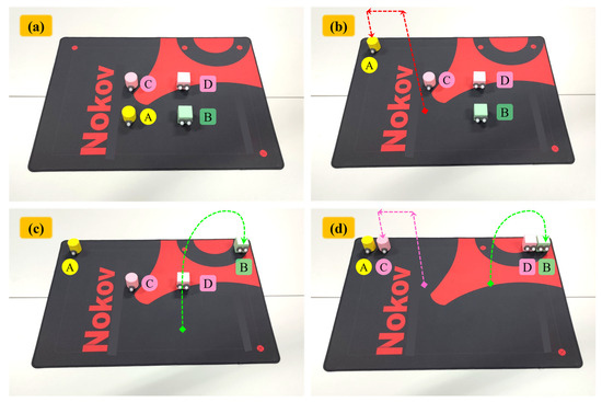
Figure 9.
Demonstration process of the desktop item classification operation task (a) initial state; (b) move A; (c) move B; (d) move C and D simultaneously.
Example: There are two cylinders and two cubes in the middle of the desktop. Now, we need to put the cylinders on the top left corner of the desktop and the cubes on the top right corner. During the demonstration of the classification operation, first, maintain the angle between the middle finger and the thumb at a constant angle (80 ± 10)°, lift cylinder A in a straight-line motion, then swing the middle finger to insert a “key frame”, as shown in Figure 2a, and move cylinder A towards the top left corner in a straight-line motion. After the movement is completed, insert another “key frame”. Finally, place cylinder A on the desktop in a straight-line motion and swing the middle finger to insert a “key frame”. This completes the movement of cylinder A. Similarly, move cube B to the designated position in an arcuate motion, and after the movement is completed, swing the middle finger to insert a “key frame”. Finally, using both hands to move the remaining C and D simultaneously, the teaching process for C is like A, and the teaching process for D is like B.
The task-level teaching trajectory in the example is shown in Figure 10a. Before being processed by the task expression algorithm, these trajectories are too complex for the robot to understand the operational logic, and the robot cannot properly replicate the task-level demonstration. By searching for “key frames”, the task-level data are segmented into small action-level trajectories. Finally, as shown in Figure 10b, the action feature matching algorithm interprets and expresses the action-level trajectories further, turning them into symbolic patterns that the robot can understand and replicate.
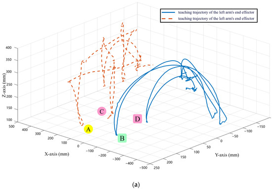
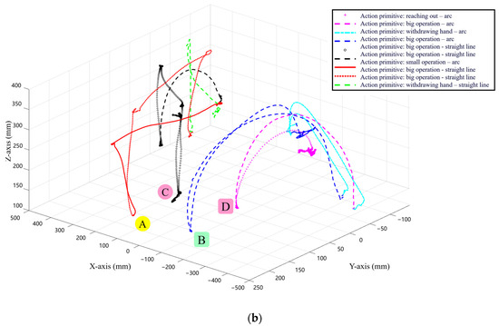
Figure 10.
Original teaching trajectory of desktop item classification operation task and the trajectory after expressing the task layer as action primitive diagram (a) original teaching trajectory; (b) trajectory after expressing the task layer as action primitive.
When humans perform complex operational demonstrations, most current algorithms cannot achieve good skill learning effects, partially due to the inability to reasonably segment the entire operational task into action clips. There are many methods for state segmentation, such as clustering, PCA, and ICA. These methods can categorize data points with similar features into one category to achieve state segmentation. ESS (experimental state splitting) uses heuristic methods to find the threshold of the feature f to segment the states, i.e., when several state variables change more simultaneously, the state will change. However, for complex operational tasks such as desktop item classification, it can be seen from Figure 10a that the original teaching data are widely distributed in space with few similar characteristics, and some trajectories are composed of multiple movements. It is difficult to effectively segment using the above methods. The “key frame” method for state segmentation can reasonably segment complex operational tasks into action clips, as shown in Figure 10b. Moreover, the “key frame” method can ensure that the accuracy of the segmentation reaches 100%.
4.5. Action Feature Matching Algorithm
Task reproduction is the process of describing the teacher’s demonstrated operation task as a set of action primitives and then transforming them into control code that the robot’s hardware can execute. This enables the robot to repeat the operation task that a human has demonstrated. Based on the current software and hardware conditions, this article proposes a new action feature matching algorithm. The purpose of this algorithm is to achieve similarity matching with the action primitive library after segmenting the task into action primitives. Then, each action primitive is described using parameterized action primitives. Finally, the overall representation of the entire operation task is completed, as shown in Figure 11.
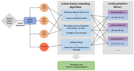
Figure 11.
Block diagram of action feature matching algorithm.
To ensure that the action feature matching algorithm can accurately represent human demonstration data as task models executable by robots, we took the following measures: (1) Data preprocessing: the collected human demonstration data were preprocessed to eliminate noise and outliers. (2) Selection of appropriate features to represent the key attributes of demonstration actions. We selected features such as action amplitude, action type, motion trajectory, and posture changes, which comprehensively reflect the characteristics of human actions when performing tasks. By matching these key attributes, robots can accurately replicate human demonstration actions. (3) To account for differences and variations among different demonstration data, we used regularization to improve the generalization ability of the model. (4) In the feature matching stage, we matched the extracted action features with the action primitives in the action primitive library. The algorithm considered multiple factors, such as feature similarity and timestamps, to ensure the accuracy and stability of the matching results.
After training and organizing using GMM and GMR algorithms, we constructed an action primitive library, whose members are shown in Table 1. Taking action primitive A as an example, it can be characterized by the following four parameters: the spatial position of the start point , the spatial position of the midpoint , the spatial position of the endpoint , and the arm end pose . Similarly, the action segment X to be matched also has these four parameters. The execution flow of the feature matching algorithm is as follows:
- (1)
- Calculate the straight-line distance from the start point to the end point of action segment X. This distance determines the magnitude of the action of X.
- (2)
- Three points in space can determine a circular arc. Using , , and to calculate the radius of the circular arc, the radius of the circular arc determines the subsequent planning type. We stipulate that if satisfies certain conditions (not specified in the question), then use S and E to directly plan the straight-line trajectory, otherwise plan the circular arc trajectory.
- (3)
- Detect whether the attitude undergoes large changes during the process. If there are large changes, use joint space planning, otherwise use Cartesian space planning.
- (4)
- Calculate the differences between and calculated in (1) and (2) and each member of the action primitive library. Select the action primitive that has the smallest deviation to represent action segment X. Finally, output the matching result with pose parameters.
5. Experiments
Firstly, to evaluate the motion execution ability of the humanoid dual-arm robot, a motion experiment in the robot’s joint space was conducted. The experiment evaluated the robot’s ability to execute the planned motion operations at the start and end points of the movement. It also used comprehensive position errors and comprehensive pose errors to assess the errors between the dual arms’ initial and final motion trajectories and the planned trajectories. The comprehensive position error and comprehensive pose error were the average errors of the manipulator at all planned points throughout the entire operational task, with values of 0.364 mm and 0.218°, respectively. The experimental results indicate that the robot can maintain good operational precision and has excellent motion execution capabilities during the motion execution process.
Then, to evaluate the performance of the humanoid dual-arm robot’s LFD algorithm, we designed two experiments—the robot’s Cartesian space circle drawing experiment and the robot’s object picking experiment—to investigate the reproducibility of both action-level and task-level demonstrations.
5.1. Experiment of Robot Drawing a Circle in Cartesian Space
5.1.1. Experimental Process
The experiment involves teaching the dual-arm robot to draw circles in space with a constant posture. After capturing the key data of the movement using a motion capture system, the Cartesian space trajectory planning algorithm processes the data and drives the humanoid robot to replicate the spatial circle drawing operation. The experiment is divided into four sections: preparation, demonstration and data processing, robotic arm trajectory planning, and experiments, as shown in Figure 12.
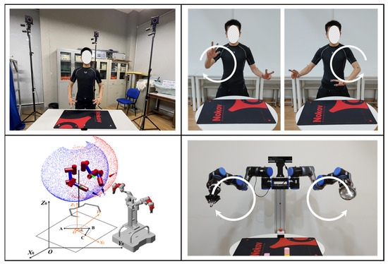
Figure 12.
Experimental process of robot drawing a circle in Cartesian space.
During the preparation stage, the NOKOV-MARS series of motion capture systems are calibrated to ensure that there are no other interference light sources or reflecting objects in the experimental area. Standard reflecting markers are then attached to both the demonstrator and the humanoid dual-arm robot.
During the experiment, the movement process of the demonstrator is shown in Figure 13a. Simultaneously, the motion capture system collects the position and attitude information of the demonstrator at the beginning and end of the movement, obtaining the teaching trajectory, as shown in Table 2.
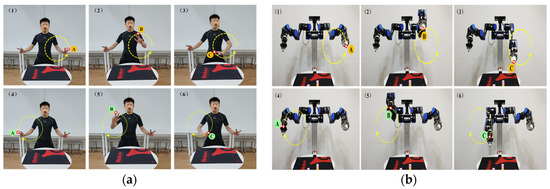
Figure 13.
(a) Teaching process of robot Cartesian space circle drawing experiment; (b) experimental process of robot drawing a circle in Cartesian space.
Table 2.
Matching the action characteristics of spatial circle drawing demonstration data.
Using the motion feature matching algorithm, the demonstration trajectory is represented as a parameterized action primitive. For this action primitive, Cartesian space circular trajectory planning is performed to obtain the circular trajectory. We input the pose data of A, B, and C spatial points into the Cartesian space trajectory planning algorithm, and solve the joint angle variation curves over time, as shown in Figure 14a,b. The horizontal axis(step) represents the step number in the time sequence, with each step being 250 ms. The vertical axis represents the joint angles, and the red and green colors distinguish the positive and negative values of joint scheduling. As can be seen from the figures, each joint angle can continuously change smoothly without sudden jumps, and the robotic arm’s end-effector maintains a stable state during motion.
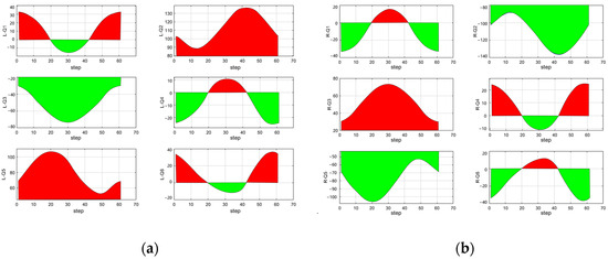
Figure 14.
(a) Circle trajectory planning in the left arm space/joint angle. (b) Circle trajectory planning in the right arm space/joint angle.
The planned trajectory data are converted into PVT data that can be executed by the reducer joint module, driving the physical robot to replicate the spatial circle drawing operation demonstrated by the teacher, as shown in Figure 13b. The position and attitude information of the robot during motion is collected using the motion capture system, as shown in Table 3. Finally, the error between the teaching trajectory and the actual running trajectory is analyzed as the evaluation criterion for the experimental effect.
Table 3.
Experimental data of robot drawing a circle in Cartesian space.
5.1.2. Analysis of Results
At first, the demonstrator demonstrates the arm’s end-effector’s motion in drawing a circle in space. The robot’s back-end program matches the demonstration data with the action primitive library using feature matching. The demonstration data are expressed and interpreted using existing action primitives, and the action-level motion is then reproduced on the physical robot platform.
Taking the left arm as an example, after the experiment, a comparison of the teaching trajectory and the actual robotic trajectory can be obtained, as shown in Figure 15. The human demonstration trajectory is not a standard circle, but after filtering and trajectory optimization, the robot’s replicated motion trajectory is basically a standard circle. Using reference Formulas (11) and (12), the comprehensive position error and comprehensive attitude error between the planned trajectory and the actual running trajectory can be calculated, as shown in Table 4.
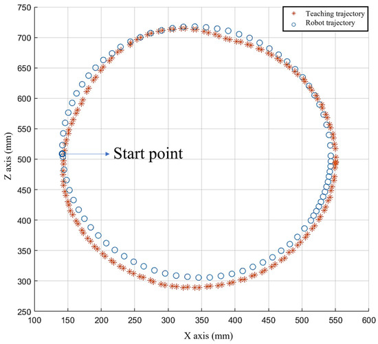
Figure 15.
Teaching trajectory and actual running trajectory of robot.
Table 4.
End-effect analysis of robot Cartesian space circle drawing experiment.
Based on the results of the comprehensive position error and comprehensive pose error presented in Figure 15 and Table 4, we can observe that the robot and its LFD system have nearly completely and accurately replicated the human demonstration actions at the motion level, achieving a very high task success rate and learning efficiency. Through this experiment, it has been proven that the humanoid dual-arm robot demonstration learning system can reproduce human demonstration actions with excellent accuracy.
5.2. Robot Object Picking Experiment
The previous experiments mainly focused on the ability of the robot demonstration learning system to learn and replicate human demonstration data at the action level. To comprehensively evaluate the ability of the humanoid dual-arm robot to perform more complex manipulation tasks, we designed this experiment.
5.2.1. Experimental Process
In this experiment, the demonstrator demonstrates a picking operation for desktop items, and the motion capture system records the demonstrator’s behavior. Then, the backend demonstration learning system can interpret the picking operation as a set of action primitives. Finally, the humanoid dual-arm robot executes these action primitives one by one to complete the learning and reproduction of human demonstration data at the task level. The experiment is divided into the following six parts: preparation, demonstration and data processing, robot movement, visual recognition, robotic arm trajectory planning, and experiments, as shown in Figure 16.
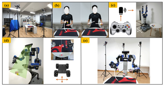
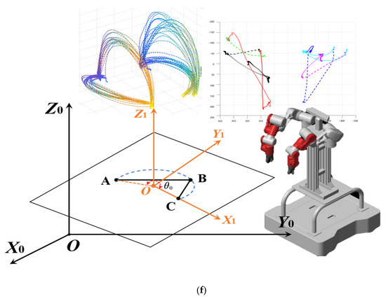
Figure 16.
Experimental process of robot object picking (a) preparation; (b) teaching and data processing; (c) robot movement; (d) recognizing objects through computer vision; (e) robot execution operation; (f) planning and simulation.
During the demonstration process, the demonstrator enters the working area of the motion capture system and demonstrates the picking operation of desktop items in its entirety. The demonstrator’s left arm palm is used as a container to receive the picked items, while the right arm end simulates the robot’s mechanical gripper. During the demonstration, the right arm picks up two items (cubic and cylindrical blocks) from the desktop and places them into the palm of the left arm. Additionally, as previously mentioned, with the aim to increase the success rate of the system’s comprehension of the demonstration data, the task-level demonstration learning necessitates the manual introduction of certain action segmentation markers utilizing the “keyframe” segmentation method. “Picking up two items on the desktop” is a complete operation task that requires multiple basic actions from both arms. The demonstration process is shown in Figure 17a, where 12 key demonstration clips are selected. These clips show the three key points in time for each basic action: “start”, “midpoint”, and “end”. Taking Figure 17a as an example, when the right arm performs a grasping action, B1 represents the start of the action, B2 represents the midpoint of the action execution, and B3 represents the end of the action.
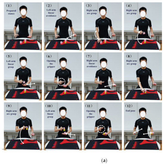
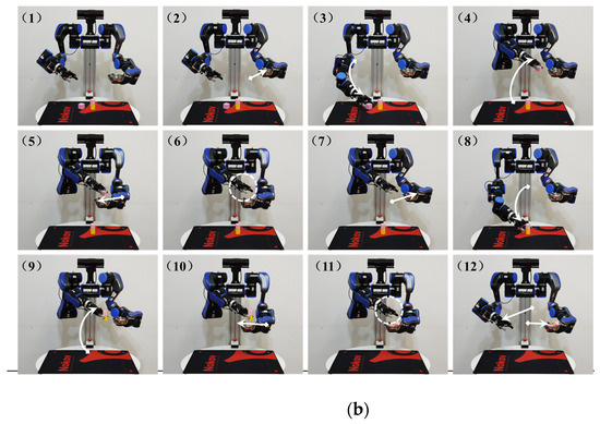
Figure 17.
(a) Teaching process of robot item picking experiment; (b) robot item picking experiment process.
After dividing the task layer into temporal combinations of action layers, the action feature matching algorithm proposed by us matches the captured teaching data from the action capture instrument with each element in the action primitive library, expressing the teaching data as action primitives with parameters, as shown in Table 5.
Table 5.
Demonstration data for item picking task.
In the visual recognition stage, we used Kinect2 as a visual sensor to detect objects within a certain field of view and provide feedback on their spatial coordinate information. This information is processed and transformed to provide spatial point inputs for various motion planning algorithms such as the starting and placement points for the picking operation. As shown in Figure 18, the ultimately recognized items to be picked up are one cubic block and one cylindrical block model. The spatial coordinate information of the items to be picked up in the dual-arm base coordinate system is shown in Table 6.
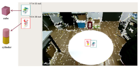
Figure 18.
Kinect2 recognizes the items to be picked up.
Table 6.
Space coordinate information of items to be picked.
During the demonstration and data processing stage, through the processing of the task-level demonstration learning-related program, the composition of action primitives for the picking operation of items in temporal order is obtained. The execution steps and purposes of these action primitives are shown in Table 7, and the ultimately planned path is shown in Figure 19a. Next, the Cartesian space circular or linear planning algorithm is used to sequentially plan the trajectories for these action primitives, obtaining the reproduced trajectory of the operation task. It should be noted that the positions of closing the gripper (B3 and F3) need to be adjusted, and these two spatial points are changed to the spatial positions of the cubic and cylindrical blocks, as shown in Table 7.
Table 7.
Composition Form of Action Primitives for Item Picking Operations.
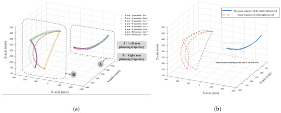
Figure 19.
(a) Track planning results of item picking experiment; (b) actual running trajectory of the robot’s two arms.
The planned trajectory data are converted into PVT data that can be executed by the joint modules of the reducer, and the physical robot is driven to replicate the demonstration operation task demonstrated by the demonstrator, as shown in Figure 17b. Through the combined operation of the above steps, the cubic and cylindrical blocks on the desktop are picked up by the right arm’s gripper and placed into the container at the end of the left arm. During the experiment, the robotic arms operate smoothly without any interference, and the picking operations are successfully completed.
The experiment is repeated 20 times, and the spatial trajectory information of the robotic arms’ end effector is recorded, as well as the successful pick-up and placement of the items by the end gripper. This information is used for subsequent quantitative analysis of the position and orientation errors of the experiment and the operational success rate of the end effector.
5.2.2. Analysis of Results
The end-effector trajectory data captured by the motion capture system are plotted in a three-dimensional coordinate system, as shown in Figure 19b. When compared with Figure 19a, the actual operating trajectory of the robotic arms’ end effector is basically consistent with the planned trajectory. To assess the differences between the actual and planned trajectories, we evaluate them through the comprehensive position error and the comprehensive pose error of the robotic arms.
Using reference Formulas (11) and (12), the comprehensive position and orientation errors between the actual and planned trajectories of the left and right robotic arms in this experiment can be calculated, as shown in Table 8. These comprehensive errors are the average errors of each robotic arm over the 251 planned points throughout the entire operation task. The comprehensive position error of the left arm is 2.624 mm, and the comprehensive pose error is 1.893°. The comprehensive position error of the right arm is 0.943 mm, and the comprehensive pose error is 0.537°. Both the comprehensive position error and the comprehensive pose error of the dual-arm robot are relatively small, demonstrating that the robot can maintain good operational precision during motion execution, exhibit high accuracy and stability in the process of action execution, and satisfy the standards for motion execution capabilities. For the 20 pick-and-place experiments, the number of successful pick-ups and placements by the gripper is recorded, and the operational success rate is calculated for each, as shown in Table 9. For this experiment, successful grasping of objects by the robot refers to the robot’s ability to accurately pick up the target object. Successful placement of objects means that the robot places the grasped target objects in the designated location. The entire process requires that the target object not fall off or tilt. Experimental results demonstrate that the robot and its LFD system can effectively learn operational skills through human demonstrations and successfully complete assigned tasks. The high success rates in grasping and placement indicate that the robot and the LFD system possess high precision and stability in action execution, as well as strong generalization and learning capabilities in task learning. The robot and the LFD system satisfy the standards for task-learning capabilities.
Table 8.
End-error analysis of robot’s item picking experiment.
Table 9.
Operation data statistics of the robotic pick-up experiment.
6. Conclusions
There are many research achievements in obtaining robotic operational skills from human demonstration data, and one of them is the trajectory-based demonstration learning method. In this paper, the humanoid dual-arm robot experimental platform is used to explore the relevant theories of the demonstration learning system, and a motion feature matching algorithm is proposed. The complex operation tasks (task layer) are decomposed into combinations of basic movements (action layer), which are effectively expressed as executable task models for robots, improving the generalization ability of demonstration learning.
The experimental results show that the demonstration learning system proposed in this paper has basic task-learning capabilities. After simulation and real-machine verification, the control algorithm can calculate effective control data for the robot according to different requirements, and the algorithm can drive the robot to replicate simple to complex demonstration operations.
With further expansion and in-depth research to enable robots to independently learn and complete tasks assigned by humans in more complex environments in the future, we are prepared to carry out research in these areas. Firstly, further optimizing the algorithms of the demonstration learning system will improve the speed and accuracy of robots in learning new tasks. Secondly, expanding the action primitive library and integrating it with autonomous navigation will explore the application of the demonstration learning system to a wider range of tasks, such as achieving autonomous navigation and interaction in complex environments and completing more complex tasks. Finally, we plan to investigate how to combine demonstration learning with other machine learning methods, such as deep reinforcement learning, to overcome the limitations of a single approach.
Author Contributions
Conceptualization, Z.C. (Ze Cui), L.K. and Z.C. (Zenghao Chen); Methodology, Z.C. (Ze Cui), L.K., Z.C. (Zenghao Chen), P.B. and D.Q.; Software, Z.C. (Ze Cui) and L.K.; writing—original draft, Z.C. (Ze Cui), L.K. and P.B.; writing—review and editing, D.Q., L.X. and Y.T.; Funding acquisition, Z.C. (Ze Cui) and P.B. All authors have read and agreed to the published version of the manuscript.
Funding
This research was supported by the National Key Research and Development Program of China (2022YFB4700501, 2022YFB2302404-02).
Institutional Review Board Statement
Not applicable.
Informed Consent Statement
Not applicable.
Data Availability Statement
Data are contained within the article.
Conflicts of Interest
The authors declare no conflicts of interest.
References
- Hu, Z.; Li, W.; Gan, Z.; Guo, W.; Zhu, J.; Gao, X.; Yang, X.; Peng, Y.; Zuo, Z.; Wen, J.Z.; et al. Learning with Dual Demonstration Domains: Random Domain-Adaptive Meta-Learning. IEEE Robot. Autom. Lett. 2022, 7, 3523–3530. [Google Scholar] [CrossRef]
- Li, H.; Ding, X. Adaptive and intelligent robot task planning for home service: A review. Eng. Appl. Artif. Intell. 2023, 117, 105618. [Google Scholar] [CrossRef]
- Hu, Z.; Gan, Z.; Li, W.; Guo, W.; Gao, X.; Zhu, J. Learning from Demonstrations Via Multi-Level and Multi-Attention Domain-Adaptive Me-ta-Learning. IEEE Robot. Autom. Lett. 2022, 7, 11910–11917. [Google Scholar] [CrossRef]
- Argall, B.D.; Chernova, S.; Veloso, M.; Browning, B. A survey of robot learning from demonstration. Robot. Auton. Syst. 2009, 57, 469–483. [Google Scholar] [CrossRef]
- Ravichandar, H.; Polydoros, A.S.; Chernova, S.; Billard, A. Recent Advances in Robot Learning from Demonstration. Annu. Rev. Control. Robot. Auton. Syst. 2020, 3, 297–330. [Google Scholar] [CrossRef]
- Jang, E.; Irpan, A.; Khansari, M.; Kappler, D.; Ebert, F.; Lynch, C.; Levine, S.; Finn, C. Bc-z: Zero-shot task generalization with robotic imitation learning. In Proceedings of the Conference on Robot Learning, Auckland, New Zealand, 14–18 December 2022; pp. 991–1002. [Google Scholar]
- Barros, J.J.O.; dos Santos, V.M.F.; da Silva, F.M.T.P. Bimanual haptics for humanoid robot teleoperation using ROS and V-REP. In Proceedings of the 2015 IEEE International Conference on Autonomous Robot Systems and Competitions, Vila Real, Portugal, 8–10 April 2015; pp. 174–179. [Google Scholar]
- Cui, Z.; Li, K.; Chen, Z.; Bao, P.; Kou, L.; Xie, L.; Tang, Y.; Zhu, D. Research on Learning from Demonstration System of Manipulator Based on the Improved Soft Actor-Critic Algorithm. In Proceedings of the 2022 IEEE International Conference on Robotics and Biomimetics (ROBIO), Jinghong, China, 5–9 December 2022; pp. 1445–1450. [Google Scholar]
- Mueller, C.L.; Hayes, B. Safe and robust robot learning from demonstration through conceptual constraints. In Proceedings of the Companion of the 2020 ACM/IEEE International Conference on Human-Robot Interaction, Cambridge, UK, 23–26 March 2020; pp. 588–590. [Google Scholar]
- Illandara, T. Active Keyframe Learning (AKL): Learning Interaction and Constraint Keyframes from a Single Demonstration of a Task. Ph.D. Thesis, Massachusetts Institute of Technology, Cambridge, MA, USA, 2022. [Google Scholar]
- Wu, Y.; Su, Y.; Demiris, Y. A morphable template framework for robot learning by demonstration: Integrating one-shot and in-cremental learning approaches. Robot. Auton. Syst. 2014, 62, 1517–1530. [Google Scholar] [CrossRef]
- Wang, N.; Chen, C.; Yang, C. A robot learning framework based on adaptive admittance control and generalizable motion mod-eling with neural network controller. Neurocomputing 2020, 390, 260–267. [Google Scholar] [CrossRef]
- Fitzgerald, T.; Goel, A.K.; Thomaz, A.L. Representing skill demonstrations for adaptation and transfer. In Proceedings of the 2014 AAAI Fall Sym-posium Series, Arlington, VA, USA, 13–15 November 2014; pp. 78–84. [Google Scholar]
- Chen, Y.; Paulius, D.; Sun, Y.; Jia, Y. Robot Learning of Assembly Tasks from Non-expert Demonstrations using Functional Ob-ject-Oriented Network. In Proceedings of the 2022 IEEE 18th International Conference on Automation Science and Engineering (CASE), Mexico City, Mexico, 20–24 August 2022; pp. 2012–2019. [Google Scholar]
- Sun, D.; Liao, Q. A Framework of Robot Manipulability Learning and Control and Its Application in Telerobotics. IEEE Trans. Fuzzy Syst. 2023, 32, 266–280. [Google Scholar] [CrossRef]
- Biagiotti, L.; Meattini, R.; Chiaravalli, D.; Palli, G.; Melchiorri, C. Robot Programming by Demonstration: Trajectory Learning Enhanced by sEMG-Based User Hand Stiffness Estimation. IEEE Trans. Robot. 2023, 39, 3259–3278. [Google Scholar] [CrossRef]
- Li, J.; Wang, J.; Wang, S.; Yang, C. Human–robot skill transmission for mobile robot via learning by demonstration. Neural Com-Puting Appl. 2023, 35, 23441–23451. [Google Scholar] [CrossRef]
- Mahalingam, D.; Chakraborty, N. Human-guided planning for complex manipulation tasks using the screw geometry of mo-tion. In Proceedings of the 2023 IEEE International Conference on Robotics and Automation (ICRA), London, UK, 29 May–2 June 2023; pp. 7851–7857. [Google Scholar]
- Wu, R.; Zhang, H.; Zhu, Y.; Zang, X.; Zhao, J. Impedance adjustment for learning human variable impedance skill. Mechatronics 2023, 95, 103036. [Google Scholar] [CrossRef]
- Evrard, P.; Gribovskaya, E.; Calinon, S.; Billard, A.; Kheddar, A. Teaching physical collaborative tasks: Object-lifting case study with a humanoid. In Proceedings of the 2009 9th IEEE-RAS International Conference on Humanoid Robots, Paris, France, 7–10 December 2009; pp. 399–404. [Google Scholar]
- Sirintuna, D.; Giammarino, A.; Ajoudani, A. An object deformation-agnostic framework for human–robot collaborative transportation. IEEE Trans. Autom. Sci. Eng. 2023. [Google Scholar] [CrossRef]
- Vianello, L.; Penco, L.; Gomes, W.; You, Y.; Anzalone, S.M.; Maurice, P.; Thomas, V.; Ivaldi, S. Human-Humanoid Interaction and Cooperation: A Review. Curr. Robot. Rep. 2021, 2, 441–454. [Google Scholar] [CrossRef]
- Liu, Y.; Li, Z.; Liu, H.; Kan, Z. Skill transfer learning for autonomous robots and human–robot cooperation: A survey. Robot. Auton. Syst. 2020, 128, 103515. [Google Scholar] [CrossRef]
- Arefeen, A.; Quarnstrom, J.; Syed SP, Q.; Bai, H.; Xiang, Y. Human grasping force prediction, measurement, and validation for human-robot lifting. In Proceedings of the International Design Engineering Technical Conferences and Computers and Information in Engineering Conference, St. Louis, MI, USA, 14–17 August 2022; American Society of Mechanical Engineers: New York, NY, USA, 2022; Volume 86212, p. V002T02A025. [Google Scholar]
- Calinon, S.; Guenter, F.; Billard, A. On Learning, Representing, and Generalizing a Task in a Humanoid Robot. IEEE Trans. Syst. Man Cybern. Part B (Cybernetics) 2007, 37, 286–298. [Google Scholar] [CrossRef] [PubMed]
- Hua, J.; Zeng, L.; Li, G.; Ju, Z. Learning for a Robot: Deep Reinforcement Learning, Imitation Learning, Transfer Learning. Sensors 2021, 21, 1278. [Google Scholar] [CrossRef] [PubMed]
- Grimes, D.B.; Chalodhorn, R.; Rao, R.P.N. Dynamic imitation in a humanoid robot through nonparametric probabilistic in-ference. In Proceedings of the Robotics: Science and Systems, Philadelphia, PA, USA, 16–19 August 2006; pp. 199–206. [Google Scholar]
- Zhao, D.; Song, S.; Su, J.; Jiang, Z.; Zhang, J. Learning bionic motions by imitating animals. In Proceedings of the 2020 IEEE International Conference on Mechatronics and Automation (ICMA), Beijing, China, 13–16 October 2020; pp. 872–879. [Google Scholar]
- Tavassoli, M.; Katyara, S.; Pozzi, M.; Deshpande, N.; Caldwell, D.G.; Prattichizzo, D. Learning Skills from Demonstrations: A Trend from Motion Primitives to Experience Abstraction. IEEE Trans. Cogn. Dev. Syst. 2023, 16, 57–74. [Google Scholar] [CrossRef]
- Franzese, G.; Rosa, L.d.S.; Verburg, T.; Peternel, L.; Kober, J. Interactive Imitation Learning of Bimanual Movement Primitives. IEEE/ASME Trans. Mechatron. 2023, 1–13. [Google Scholar] [CrossRef]
- Schneider, M.; Ertel, W. Robot learning by demonstration with local gaussian process regression. In Proceedings of the 2010 IEEE/RSJ International Conference on Intelligent Robots and Systems, Taipei, Taiwan, 18–22 October 2010; pp. 255–260. [Google Scholar]
- Liu, F.; Sun, F.; Fang, B.; Li, X.; Sun, S.; Liu, H. Hybrid Robotic Grasping with a Soft Multimodal Gripper and a Deep Multistage Learning Scheme. IEEE Trans. Robot. 2023, 39, 2379–2399. [Google Scholar] [CrossRef]
- Song, Y.; Wen, J.; Liu, D.; Yu, C. Deep Robotic Grasping Prediction with Hierarchical RGB-D Fusion. Int. J. Control. Autom. Syst. 2022, 20, 243–254. [Google Scholar] [CrossRef]
- Wei, H.; Pan, S.; Ma, G.; Duan, X. Vision-Guided Hand–Eye Coordination for Robotic Grasping and Its Application in Tangram Puzzles. AI 2021, 2, 209–228. [Google Scholar] [CrossRef]
- Sasabuchi, K.; Wake, N.; Ikeuchi, K. Task-Oriented Motion Mapping on Robots of Various Configuration Using Body Role Division. IEEE Robot. Autom. Lett. 2020, 6, 413–420. [Google Scholar] [CrossRef]
- Chou, G.; Wang, H.; Berenson, D. Gaussian Process Constraint Learning for Scalable Chance-Constrained Motion Planning from Demonstrations. IEEE Robot. Autom. Lett. 2022, 7, 3827–3834. [Google Scholar] [CrossRef]
- Lobbezoo, A.; Kwon, H.J. Simulated and Real Robotic Reach, Grasp, and Pick-and-Place Using Combined Reinforcement Learning and Traditional Controls. Robotics 2023, 12, 12. [Google Scholar] [CrossRef]
- Radosavovic, I.; Xiao, T.; James, S.; Abbeel, P.; Malik, J.; Darrell, T. Real-world robot learning with masked visual pre-training. In Proceedings of the Conference on Robot Learning, Auckland, New Zealand, 14–18 December 2022; pp. 416–426. [Google Scholar]
- Chebotar, Y.; Vuong, Q.; Hausman, K.; Xia, F.; Lu, Y.; Irpan, A.; Kumar, A.; Yu, T.; Herzog, A.; Pertsch, K.; et al. Q-transformer: Scalable offline reinforcement learning via autoregressive q-functions. In Proceedings of the Conference on Robot Learning, Atlanta, GA, USA, 6–9 November 2023; pp. 3909–3928. [Google Scholar]
- Kehoe, B.; Matsukawa, A.; Candido, S.; Kuffner, J.; Goldberg, K. Cloud-based robot grasping with the google object recognition engine. In Proceedings of the 2013 IEEE International Conference on Robotics and Automation, Karlsruhe, Germany, 17 October 2013; pp. 4263–4270. [Google Scholar]
- Pérez-D’Arpino, C.; Shah, J.A. C-learn: Learning geometric constraints from demonstrations for multi-step manipulation in shared autonomy. In Proceedings of the 2017 IEEE International Conference on Robotics and Automation (ICRA), Singapore, 29 May–3 June 2017; pp. 4058–4065. [Google Scholar]
- Ebert, F.; Finn, C.; Dasari, S.; Xie, A.; Lee, A.; Levine, S. Visual foresight: Model-based deep reinforcement learning for vision-based robotic control. arXiv 2018, arXiv:1812.00568, 6–25. [Google Scholar]
- Si, W.; Wang, N.; Yang, C. A review on manipulation skill acquisition through teleoperation-based learning from demonstration. Cogn. Comput. Syst. 2021, 3, 1–16. [Google Scholar] [CrossRef]
- Cohen, P.R.; Chang, Y.H.; Morrison, C.T.; Beal, C.R. Learning and Transferring Action Schemas. In Proceedings of the IJCAI 2007, Hyderabad, India, 6–12 January 2007; pp. 720–725. [Google Scholar]
- Rozo, L.; Calinon, S.; Caldwell, D.G.; Jimenez, P.; Torras, C. Learning Physical Collaborative Robot Behaviors from Human Demonstrations. IEEE Trans. Robot. 2016, 32, 513–527. [Google Scholar] [CrossRef]
- Castro, A.; Silva, F.; Santos, V. Trends of Human-Robot Collaboration in Industry Contexts: Handover, Learning, and Metrics. Sensors 2021, 21, 4113. [Google Scholar] [CrossRef] [PubMed]
- Markatou, M. Mixture Models, Robustness, and the Weighted Likelihood Methodology. Biometrics 2000, 56, 483–486. [Google Scholar] [CrossRef]
Disclaimer/Publisher’s Note: The statements, opinions and data contained in all publications are solely those of the individual author(s) and contributor(s) and not of MDPI and/or the editor(s). MDPI and/or the editor(s) disclaim responsibility for any injury to people or property resulting from any ideas, methods, instructions or products referred to in the content. |
© 2024 by the authors. Licensee MDPI, Basel, Switzerland. This article is an open access article distributed under the terms and conditions of the Creative Commons Attribution (CC BY) license (https://creativecommons.org/licenses/by/4.0/).