1. Introduction
A constant increase in the performance of computing systems is achieved by increasing the number of computing cores. To work together, these cores require a high-performance network that is resistant to congestion and node failures. One way to improve resiliency and performance is to apply new topologies for networks-on-chip (NoCs) [
1].
Network topologies can be classified as either physical or logical. Physical topologies are determined by the way the cores in a real chip are connected, and the logical topology is determined by a graph of connections between network nodes [
2]. At the same time, simplifications are often adopted in a logical topology, according to which the connections have a fixed length and the same bandwidth, and the nodes of the graph are homogeneous. NoC logical topologies are distinguished by a wide variety of graph structures and can be used to test and find the best connection options. At the same time, the implementation of the topology during synthesis at the physical level is determined by the algorithms of the synthesizing CAD of integrated circuits. This allows the developer to abstract away from the physical implementation by performing design and modeling first at a high level, after which (if the network satisfies the design requirements) descending to a lower level of the HDL model. The approach where NoC design relies on a logical topology is called the Topological approach [
3] and is described in
Section 2.
In this paper, we will simulate the NoC built on the basis of the circulant topology and compare it with the 2D mesh topology. A description of the features of the circulant (as well as 2D mesh and 2D torus topologies) is given in
Section 3. In this work, we will not only compare the routing efficiency and its fault tolerance for different types of topologies but also try to develop a unified approach to routing in NoCs based on the use of a virtual coordinate system [
4].
The proposed routing methods are built by analogy with wireless self-organizing networks. The key elements of routing are virtual coordinates and the greedy advance principle [
5]. They were developed for wireless self-organizing networks but can also be applied to NoCs. The application of virtual coordinates to dynamic network configurations is a fairly new research direction. It is noted in [
6] that the main difficulty of virtual coordinates is to specify directions, i.e., to switch to vector analysis. In our study, we propose an original solution to this problem, including the area of ring graphs.
NoCs have a number of features compared to wireless ad hoc networks. The main difference is that the structure of the NoC must be determined at the time of chip manufacturing and, in general, cannot be changed later. This means that the network configuration is static, and the neighbors of any node are fixed. During the operation of the chip, individual nodes may become faulty for a certain period of time. The set of working nodes in the NoC in this case will resemble the dynamic configurations of a self-organizing wireless network. Therefore, NoC is a convenient framework for using virtual coordinates, and routing methods developed for wireless ad hoc networks are well suited for routing in high-load NoCs [
7]. In our work, we presented two new algorithms: an algorithm for assigning virtual coordinates to an arbitrary node of the circulant and an algorithm for constructing a route between any two nodes of the circulant.
The approach presented using the coordinate grid [
8] does an excellent job with routing in the case of a 2D mesh topology and during the actual NoC operation under conditions of overloads of individual nodes. But the circulant topology is a symmetric graph, and the assignment of coordinates in it has significant features. These singularities are due to the fact that there exists a non-trivial first homotopy group.
Section 4 and
Section 5 are devoted to the choice of a coordinate system for the circulant and the modernization of the greedy packet forwarding method in NoCs.
In
Section 6, the performance and fault tolerance of the proposed method are analyzed. The mesh and circulant topologies are compared.
Section 7 contains the main conclusions of our study.
The major contributions of this paper are as follows:
A virtual coordinate system for numbering nodes in the circulant topology is proposed;
The principle of greedy promotion in circulant topology is formulated;
The rules for constructing the shortest routes between the two nodes based on a virtual coordinate system are formulated;
A technique for calculating optimal network configurations is described;
The comparison of communication stability in mesh and circulant topologies in the conditions of the failure of network nodes is made;
NoCs with mesh and circulant topologies under load and failures are modeled and investigated.
2. Topological Approach
NoCs came to replace shared buses when integrated circuit design technology reached a level where it became possible to place tens and hundreds of processor nodes on a single chip. Then, the buses, as a communication infrastructure, became too slow and insufficient to transfer huge data flows between individual nodes, primarily due to the fact that when transmitting over a classical bus [
8,
9], they can only serve one transmission at a time. This shortcoming is partially mitigated by bus segmentation and the use of separate additional paths (DMA, Streaming interface, etc.) [
10,
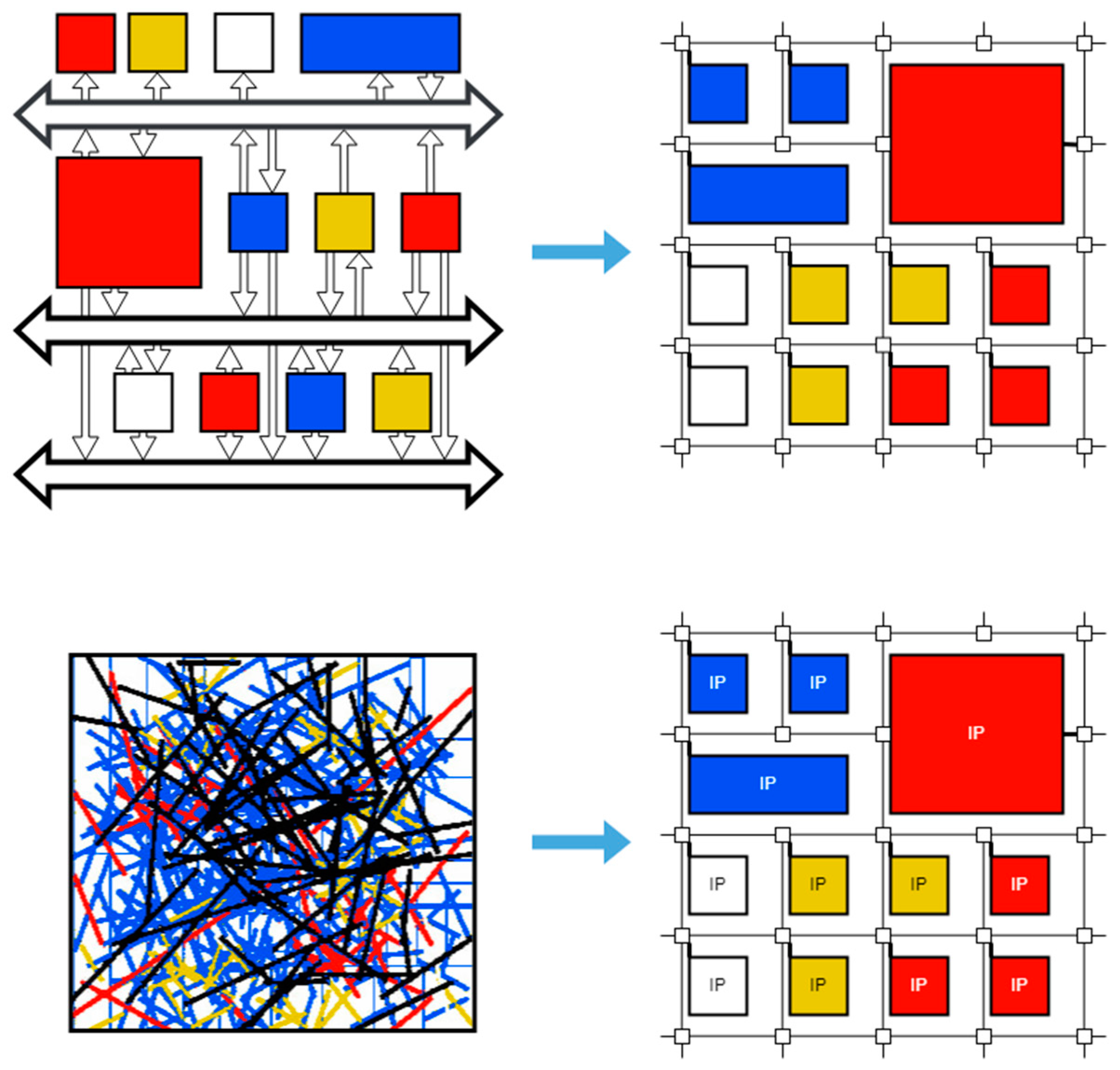
11], serving intensive traffic flows. But, this is still not enough for multiprocessor systems with tens and hundreds of nodes. In the early 2000s, the concept of NoCs was proposed. Its main idea is to organize transmission on a chip by analogy with classical communication networks and divide the communication subsystem into separate short segments through which data are transmitted simultaneously and in parallel (
Figure 1). In accordance with the new approach, transmission control is carried out using routers, and communication routes pass between NoC macroblocks [
12,
13]. This made it possible, at the initial stages of NoC design, to move away from the irregular placement structure of NoC macroblocks and take into account their spatial arrangement on the silicon die (upper part of
Figure 1), as well as simplify the solution to the problem of confusion of connections, making them more regular and shorter (bottom part
Figure 1).
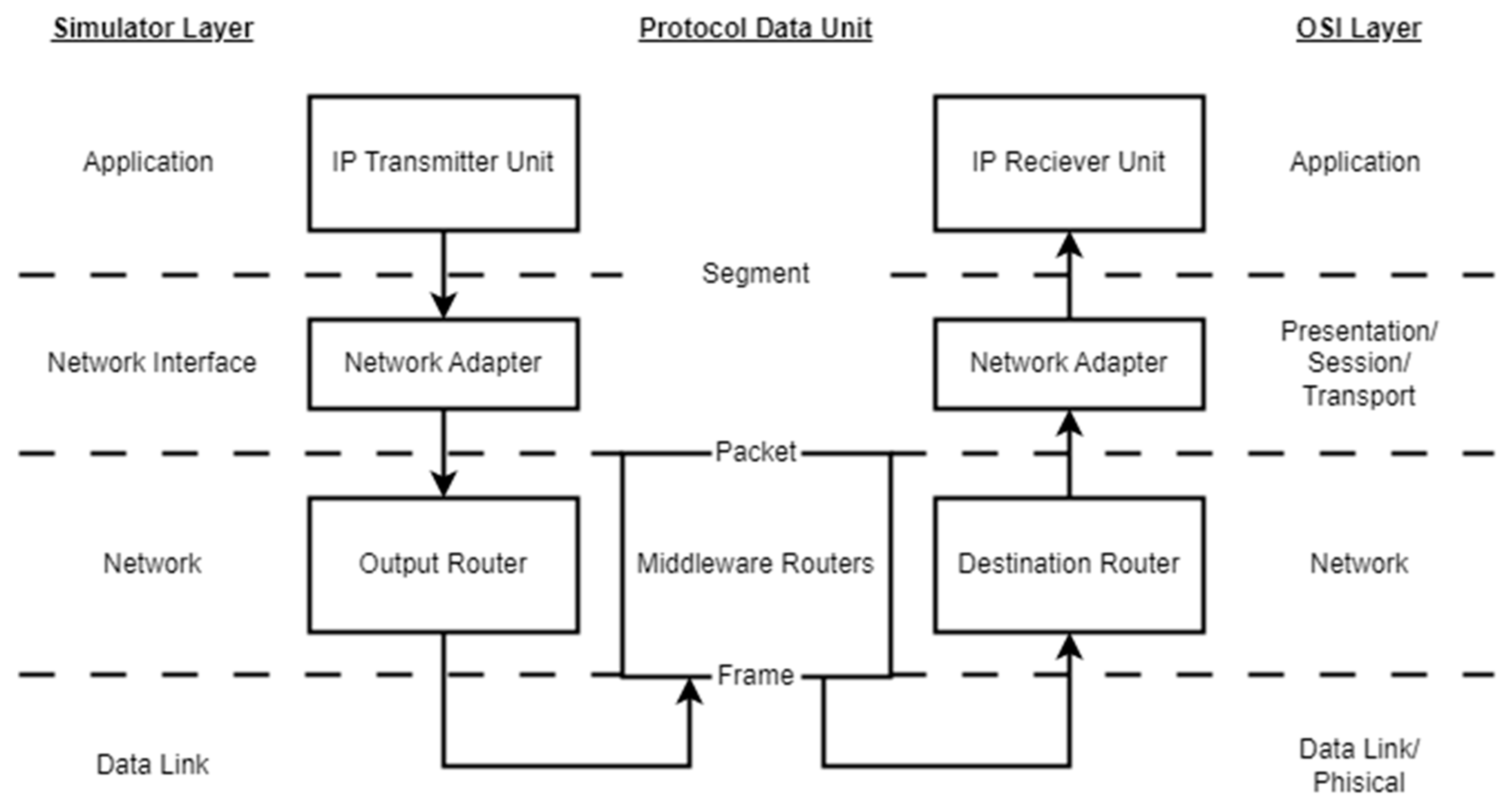
NoCs cannot directly transfer the multilayer OSI model [
14] from classical communication networks. In general, there is no need to provide data recovery encoding, data encryption, or the ability to connect new subscribers to the network; at the same time, the length of the connections is very short, routers must be very simple, etc. It is possible to map the OSI levels to the NoC communication subsystem [
15], but this will not be entirely accurate (
Figure 2). Therefore, it is required to develop one’s own approaches and methods for the NoC design.
The idea of organizing a communication subsystem in a NoC in the form of a fine-grained mesh-like structure turned out to be very convenient and has been the main one in the NoC design for a long time. For example, this is how the communication subsystem is organized in Intel Xeon E5 class processors (it even received the name Intel Mesh Interconnect) [
15,
16] or the ET-SoC-1 chip [
17] from Esperanto Technologies consisting of 1089 + 4 64-bit RISC-V processor units. Also, with the imperfection of CAD tools for the synthesis of integrated circuits, it is convenient to use simplification when designing and representing individual macroblocks of the network in the form of rectangles compactly located on the die area.
But it soon became clear that the topology of the 2D mesh does not have the best topological characteristics (first of all, the diameter and mean path length (MPL) matter, but bisection width, vertex degree, number of connections, and others are also important). For this reason, the same Intel company used the ring topology (for example, in the Intel Core i9-9900KS) [
18], the torus topology (for example, in Ice Lake-SP) [
19], and many others in its chips.
In addition, if the final chip is looked at under a microscope, one can hardly see the original fine-grained structure. And if we talk about the implementation of a NoC on an FPGA chip (which has already reached such sizes that it can fit a network of tens and hundreds of nodes [
20]), then it is even more difficult to maintain the initial abstraction in it with the representation of individual macroblocks in the form of rectangles due to uneven distribution of chip resources on the FPGA die area. Also, the simplification that the main connection routes between routers pass between macroblocks does not correspond to reality because the chip is initially multilayered, and the connections go through several metal layers.
Thus, scientists researching NoCs soon realized that sticking to the original idea of representing a NoC, as shown in
Figure 1, does not make any sense. Retaining the concept of short connections between routers, the way routers are connected can be thought of as a graph called a network topology (not to be confused with a chip topology). In this case, we can use simplifications, such as an unweighted graph and the same size of graph vertices. In high-level design and NoC modeling, it is not necessary to take into account the features of the technology and the size of separate IPs because this will be taken into account in the next stage of HDL modeling and network synthesis, which are performed at the CAD level. The graph does not have to be a 2D mesh. Moreover, the 2D mesh topology is not optimal [
21,
22]. Even if it is called regular (the placement of nodes relative to each other and the connections between them can be described by regular rules), it is not homogeneous.
There are other graph structures that are better suited to be used as a network topology. In addition to 2D mesh, different scientists have proposed a large number of different topologies [
23] (for example, Spidergon [
24], Chordal ring [
25], BFT [
26], WK-recursive [
27], hierarchical [
28,
29], etc.). Circulants occupy a worthy place among them due to their good diameter and MPL parameters, as well as symmetry to their vertices. But offering a topology is not enough. Developing efficient, low-cost, and error-tolerant routing algorithms is needed, which the following sections of this article are aimed at.
We also note that the approach that we call Topological is widespread; it is used in various areas where communication networks are established [
30] since it is convenient to study the topology properties of networks using graph theory (for example, as in [
30,
31], dedicated to supercomputers, or as in [
32,
33], dedicated to decision-making in communication networks). Network information transmission delay is related to the diameter and MPL of the graph, while network fault tolerance is connected to the connectivity of the graph [
34,
35,
36]. In the following sections, we will rely on the Topological approach, considering NoC and routing algorithms in it at a high level of its topology and abstracting from the NoC physical implementation for simplicity.
3. Circulant Versus Mesh and Torus
Assume that it is necessary to synthesize a NoC with a circulant topology of the type
with an arbitrary number of generators, which is a special case of ring graphs (
Figure 3). In a ring topology, all nodes are connected in series. The null node is adjacent to the last node. Also, every node has regular connections with a shift of several nodes clockwise and counterclockwise. Hereinafter, we use the standard notations given in reference [
35].
The total number of circulant nodes is assumed to be , and the lengths of cyclic shifts (generators) are denoted as .
The nodes of the circulant will be denoted by capital Latin letters (the letter is reserved for the designation of the circulant). The nodes are numbered, starting from zero, so that each node is assigned a number from 0 to .
Let us compare the new topology with the 2D mesh. It should be noted that the topology of 2D torus and circulant has a number of significant differences from the topology of 2D mesh. They are as follows:
The 2D torus and circulant do not have the kind of boundary vertices that the 2D mesh topology has. The 2D mesh has four corner vertices with two neighbors and a large number of edge vertices with three neighbors [
7,
37].
There are many symmetry groups for 2D torus and circulant topologies. The circulant is completely invariant with respect to any of its nodes. A transformation that transfers one of the nodes to another completely preserves the original topology configuration. These properties allow us to significantly upgrade our earlier approach [
7] based on the use of virtual coordinates for the 2D mesh topology.
Let us consider the problem of node density. Usually, the 2D mesh topology is represented as a square since this is the most optimal shape for this topology [
22] (where
is the square of the number). In this case, for a network of
nodes, the maximum number of neighborhoods between arbitrary nodes does not exceed
. The maximum number of neighborhoods allows judging the size (diameter) of the network as
; that is, for a 2D mesh:
Let us estimate the size of a 2D circulant (which has two generators). Such a family of circulants is closest to the 2D mesh topology since each node of the 2D circulant also has four neighboring nodes. To estimate the node density, it is necessary to find a recursive formula for the number of nodes in the neighborhood.
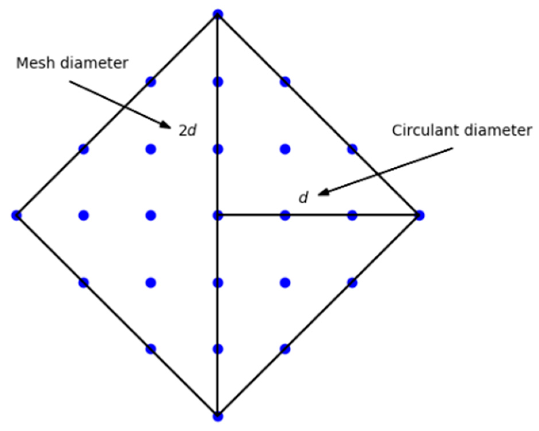
Consider a 2D mesh topology. Let us select a node in the center of the graph and find how many nodes are in each neighborhood of the selected node (
Figure 4).
Based on
Figure 4, we formulate several statements:
Only the node itself is located in the zero neighborhood;
There are four nodes in the first neighborhood;
There are eight nodes in the second neighborhood;
There are 12 nodes in the third neighborhood;
Etc.
In general, a neighborhood contains
nodes, and the total number of nodes
in
neighborhoods is:
This formula is also valid for a two-dimensional circulant. This fact is clearly illustrated in
Figure 4. If we imagine that the number of neighborhoods to the current node along the largest generator is plotted along the
axis and the smallest generator is along the
axis.
Thus, the 2D mesh topology is equivalent in node density to the 2D circulant, and the circulant with three generators (three-dimensional) corresponds to the 3D mesh topology [
38,
39]. In this case, the diameter of the circulant is less than two times. This is due to the symmetry that the circulant has. As mentioned earlier, the circulant is invariant under a transformation that takes an arbitrary vertex to any other. Therefore, the diameter of the circulant will be equal to the maximum number of neighborhoods in Equation (2), and it will be twice as large in a 2D mesh topology (
Figure 4).
It should be noted that Equation (2) is valid for the optimal circulant, which has the smallest possible diameter for a given number of nodes. That is, optimal circulants can be obtained for sets of 13, 25, 41, 61, 85, 113, etc., nodes. But complete filling the rhombus in
Figure 4 requires finding the lengths of the generators of the circulant, which is not a trivial problem and has been solved only for some families of circulants [
40]. This problem (as well as the problem of the shortest MPL search) is to be solved in our future studies. So far, one can only hypothesize that this average will be minimal for the case of dense circulants. For example, consider a dense circulant
with a diameter of 2 (
Figure 5).
For a two-dimensional circulant, the maximum number of neighborhoods can be estimated using Equation (3). In this case, it is equal to:
For example, for a circulant with sixty-four nodes, the maximum number of neighborhoods will be six.
4. Virtual Coordinate System
Setting virtual coordinates involves several difficulties, the first of which is the marking of directions. For this purpose, we apply the greedy advancement method. The second difficulty is the choice of anchors relative to which the coordinates are set. This problem is solved using a symmetry group that leaves the chosen topology unchanged. Since the circulant is symmetric with respect to the transformation translating any two vertices into each other, it is sufficient to specify one anchor.
On-chip networks have a fixed connectivity graph, and periodic disconnections of certain nodes give dynamics to the process. Our approach is designed for networks, such as networks-on-chip or supercomputer networks.
The main task of routing in a NoC is to determine the path between two nodes,
and
, with the least number of hops. From a mathematical point of view, this is a typical integer optimization problem in which it is required to minimize the sum of the modules of the coefficients:
from the expansion of the number
in terms of the lengths of the generators:
The sum in Equation (4) shows the neighborhood relative to node that node falls. By neighborhood, we mean the set of nodes equidistant from a given node by the minimum number of possible hops.
All variables in Equations (4) and (5) are integers. The sign of the integer indicates the direction of rotation. A positive sign coincides with the direction from to and a negative sign changes the direction from to . The value of the corresponding coefficient shows how many transitions must be made along the generator in order to reach the final node of the route. Transitions along different generators can alternate in an arbitrary order. The main thing is that in the end, all the transitions are given by the coefficients in Equation (5), where .
Let us formulate the algorithm of address assignment in the form of a pseudo-code:
| Algorithm 1 Address Assignment Algorithm |
| 1 | define center node |
| 2 | i = 1 |
| 3 | while (at least one node in -neighborhood exist) |
| 4 | build i-neighborhood relative to the central node |
| 5 | assign coordinates to nodes from the -neighborhood |
| 6 | i = i + 1 |
| 7 | end while |
| 8 | stop partitioning process |
The problem of finding coefficients in Equation (5) is solved by the enumeration of integers. In this case, due to the limited scope of these values, the boundaries of the enumeration can be determined in advance. The range of possible values of the coefficients is given in Equation (3).
Before formulating the basic routing rules for a circulant, it is necessary to describe the procedure for determining the coordinates for its nodes. Virtual coordinate systems are widespread in communication networks, especially in wireless networks [
6,
41,
42]. In the case of the NoC with a circulant topology, everything is simpler since the circulant graph has many symmetry groups, and all vertices in it are equivalent, which greatly simplifies its labeling since the coordinate system will be universal and can be tied to any node of the graph.
Let us set one of the nodes, for example,
, as the origin, assigning the number 0 to this node. Then, the number of an arbitrary node
can be decomposed into generators so that the sum of the modules of its coordinates from 1 to
is (the zero coordinate is a full turn; it is a service and is not taken into account when routing) is the minimum:
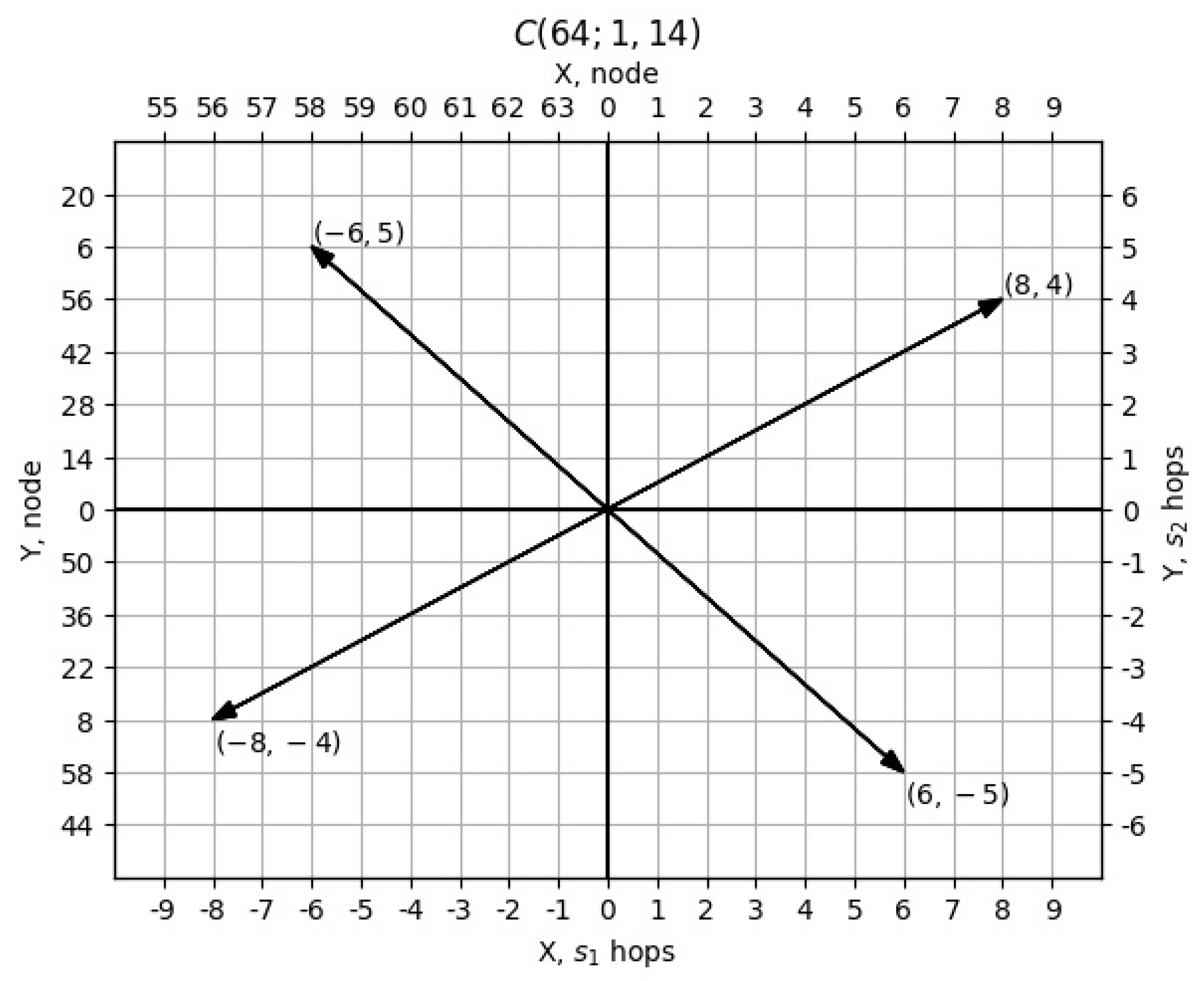
Values should be used as virtual coordinates of node . These coordinates completely determine the position of node , if the origin is known. Thus, the coordinate system for the circulant is defined.
Figure 6 shows the assignment of coordinates for the circulant
. Circulant nodes are defined in Cartesian coordinates. The
coordinate of an arbitrary node is plotted along the
-axis, and the
coordinate of the given node is plotted along the
-axis (
is not taken into account). Every node of the circulant will have its own position on the graph. Moreover, the optimal values of the coordinates of all nodes will fit inside the rhombus, as shown in
Figure 4.
Since the circulant is a repeating periodic structure, the nodes in Graph 2 will also repeat. So, in
Figure 6, four vectors,
, transfer any node into itself.
Figure 6 illustrates this statement for node 0.
The issue of the unambiguous assignment of coordinates to circulant nodes also requires discussion. With the correct choice of the generators’ lengths, all the coordinates inside the rhombus will be uniquely determined. But, some of the nodes located on the boundary can obtain double coordinates if the circulant is not dense. Thus, for the circulant , the nodes from the first five neighborhoods will be uniquely determined. The total number of such nodes will be 61. There will be three nodes left, and they will be located in the sixth neighborhood, which can contain twenty-four nodes. These three nodes, 19, 32, and 45, are ambiguously defined; for each of them, there are two different sets of coordinates: or ; or ; and or . Both of these sets satisfy the condition for the sum of the first and second coordinates to be minimal.
The problem of finding circulants that completely fit into the base rhombus (as in
Figure 4) requires further study since such circulants will have the useful property that all nodes in them are uniquely defined. But, this is not the purpose of the current study.
5. Routing Methods in a Network with a Circulant Topology with a Virtual Coordinate System
In the previous section, we proposed a method for assigning coordinates to network nodes. For such a coordinate system, it is required to develop a method for finding the shortest routes for packets to move between two arbitrary nodes, and .
There are two ways to solve this problem. The first method is based on the fact that the circulant is invariant with respect to any of its nodes. Thus, if the absolute numbers of nodes
and
are restored from the coordinates, then the difference
can be calculated from them. This difference can be correlated with the virtual coordinates of the node
, which specify how many hops, in which direction, and along which generators must be performed to reach the destination node (
is not important for routing). The choice of which generator should be followed first by hops may depend on the routing algorithm but does not affect the length of the entire path. The problem is that in every node, it is necessary to either store a table of correspondence of absolute coordinates to virtual ones or perform the conversion procedure from virtual coordinates to absolute coordinates two times every time and then once back. In itself, the procedure for converting from absolute to virtual coordinates is essentially a method for calculating the number of hops along the corresponding generators from one node to another and has already been described in [
43]. In addition, there are methods to simplify calculations, if one uses not one reference zero node but several [
7,
44]. Thus, the first method is reduced to classical routing methods based on the absolute coordinate system.
The second way to solve the routing problem (using virtual coordinates) proposed in this paper is to perform calculations with virtual coordinates of nodes. Consider the difference between the virtual coordinates of nodes
and
. It is:
If transfers along the generators, are performed, and then a route from to will be provided. The problem is that such a route will not always be optimal.
Let us formulate a criterion for the optimality of the route. Denote the maximum number of neighborhoods of the circulant as
. If the modulo sum of non-zero coefficients in Equation (7) is less than or equal to
, then:
This solution is final and coincides with the optimal one. Graphically, this means that the end node of the route lies inside the optimal rhombus centered at the start node of the route (
Figure 4).
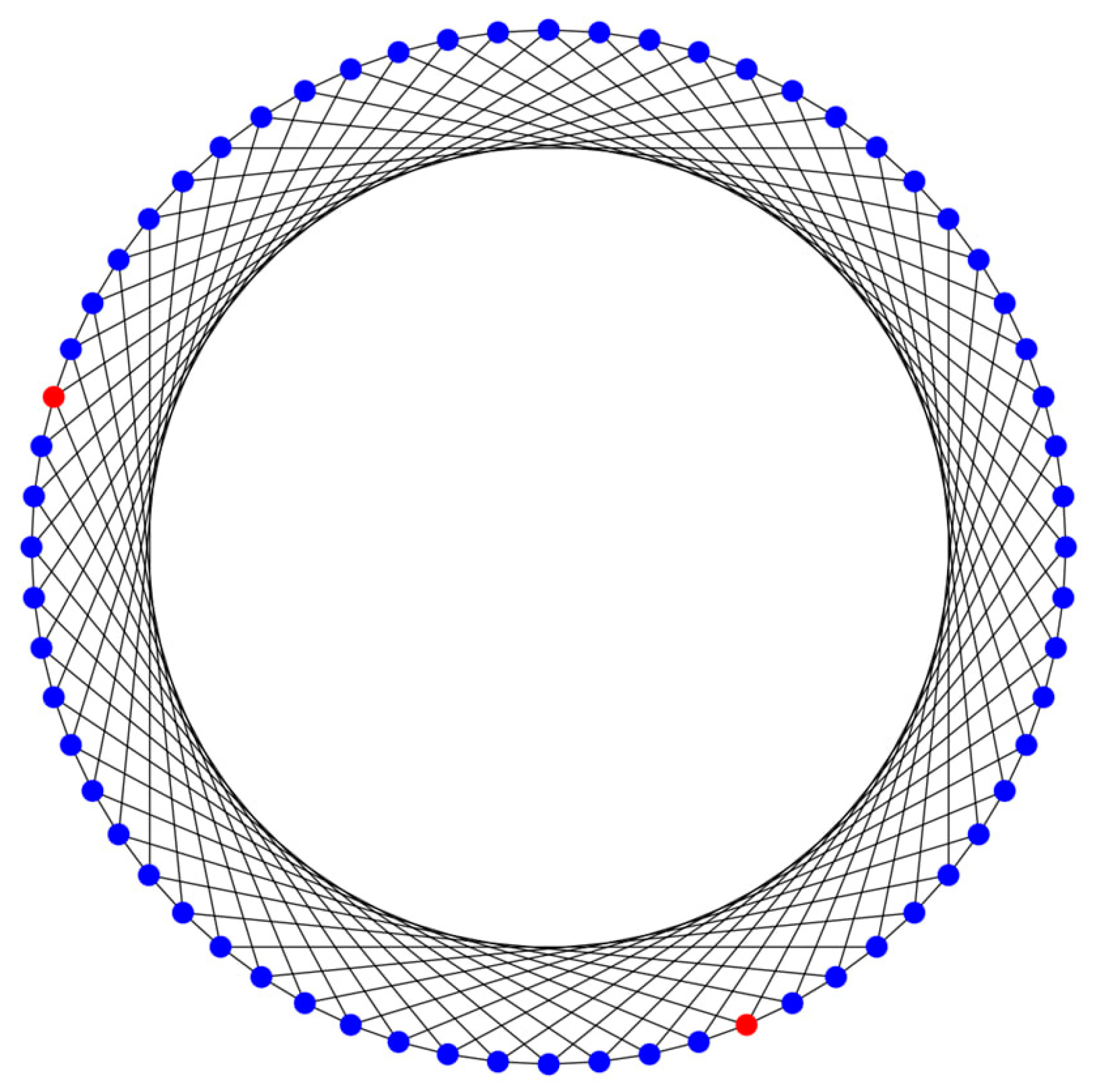
As an illustration, let us find a route between nodes
and
(red dots in
Figure 7) in the circulant
.
The difference in coordinates between these nodes is
, and the sum of the neighborhoods is less than six. That is, this is the optimal path corresponding to node
.
Figure 8 graphically shows the route between nodes 29 and 52.
But another situation is also possible when the sum of the modules of the coefficients exceeds . In these cases, additional transformations are needed.
Section 4 showed that there are several vectors that map one node to itself. These vectors must be added to the difference of those nodes whose sum of modules of coefficients exceeds
. Moreover, one needs to add all the vectors separately. One of the results of this summation will satisfy the minimum sum requirement in Equation (8).
As a graphical illustration of finding a route, consider finding a path between nodes and in the circulant . The shortest path between 12 and 24 nodes is . But if we directly subtract the coordinates of the nodes, we obtain the following result: . But if the sum over this vector and the vector is performed, the result will be the desired solution: .
Let us give one more example of building a route between nodes and . The difference between the coordinates is ; that is, the sum of the coordinates is greater than the diameter. But if we add the transfer vector to this difference, the optimal solution will be obtained.
The second method involves finding the difference between the coordinates of the nodes at the end and the beginning of the route. To this result, we should sequentially add four fixed vectors and choose the smallest vector from the obtained five vectors.
Thus, in this section, we have completely defined the rules for computing virtual coordinates for implementing the routing method in a network with a circulant topology (we name it the Greedy Promotion Algorithm). Our method is applicable to networks of different sizes without any modernization, but the technology limitation is to build a chip with hundreds of cores. That is, the limiting factor is the technology of integrated circuit development with the resources for a large number of processing cores rather than routing algorithms.
6. Evaluation and Discussion
A key element in comparing routing between mesh and circulant topologies is network load testing; that is, the study of the possibility of building routes in case of the failure of a certain number of nodes in NoCs [
7,
45].
When conducting such testing, we used a simplified path construction mechanism. For two nodes of the circulant between which it is necessary to build a route, we restore their numbers from the coordinates, and using these numbers, we find the difference—a new vector of numbers. For this difference, we set the coordinates, and these coordinates will completely define the route. The second coordinate will show how many hops need to be made along the small generator, and the third coordinate will show the number of transfers along the large generator.
Because the order of hops can be changed arbitrarily, there are multiple routes between two nodes. If one of the nodes fails, an alternative route can always be chosen. We will randomly choose which of the generators to make the hop. Moreover, when choosing, the remaining number of large and small hops should be taken into account. When faulty nodes appear and their number increases, the next node of the route may not be operational. In this case, the transfer along the small generator must be replaced by the transfer along the larger generator, and vice versa. If there are no hops along the large generator, such a hop is still made, then the hop along the small generator, and the hop along the large one back. Thus, the stability of routing will increase, but the route will lengthen.
For comparison, two NoC configurations of 256 nodes were selected. One configuration is a 2D mesh network with a 16 by 16 node (mesh16x16) configuration. The second is the circulant
(
Figure 9). The routing methods for these networks were Dijkstra’s algorithm [
46], the Greedy Promotion Algorithm for mesh [
7], and the new version of the algorithm described above for the circulant. The computational complexity of the route construction algorithm for the circulant is much simpler since it contains only six operations with the addition of two plane vectors and a comparison of the lengths of five vectors, while the route construction algorithm on mesh topology contains loops within which the operations of the addition, multiplication, and comparison of integer variables are performed. However, a countable number of operations depends on the size of the NoC.
In the process of modeling, we fixed the beginning and end of the route, gradually increasing the number of faulty nodes and counting the number of faulty routes. Routes were built by the methods described earlier. The results of running several experiments with the same parameters were averaged.
For simulation, the Newxim simulator [
47] (a deeply revised version of the well-known Noxim simulator [
48,
49]) is used, which supports circulant topologies and the ability to easily implement any custom routing algorithms, as well as many automation tools that greatly speed up and facilitate the process of modeling and processing results.
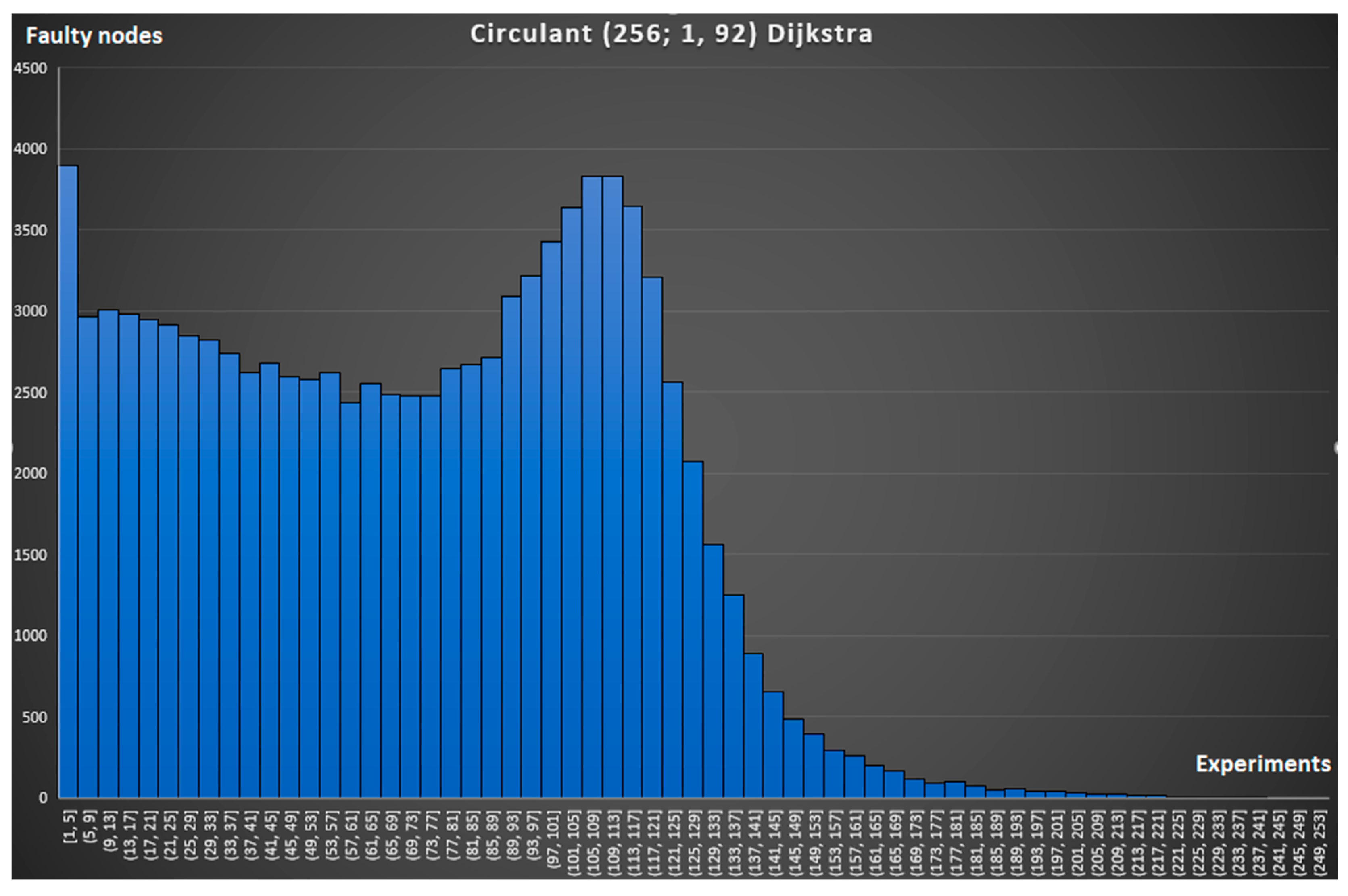
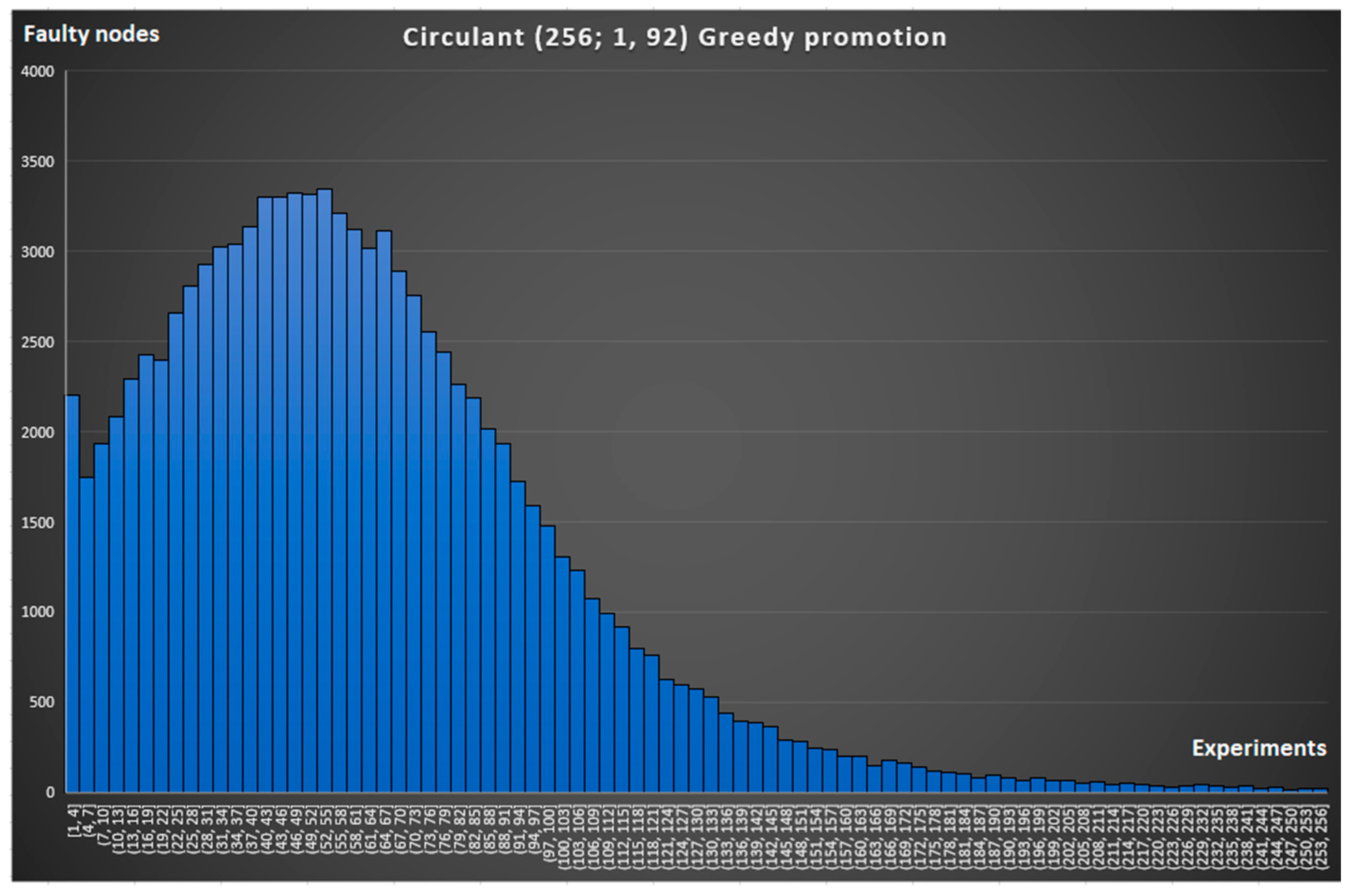
The first two graphs in
Figure 10 and
Figure 11 correspond to a circulant topology with ideal routing (when all possible routes calculated by the classical Dijkstra algorithm [
43] are known) and with routing based on the Greedy Promotion Algorithm. The
X-axis shows the number of faulty nodes until the packet reaches a dead-end and can no longer move through the network (connection break). The
Y-axis displays the number of experiments with successfully built routes that fell into this interval.
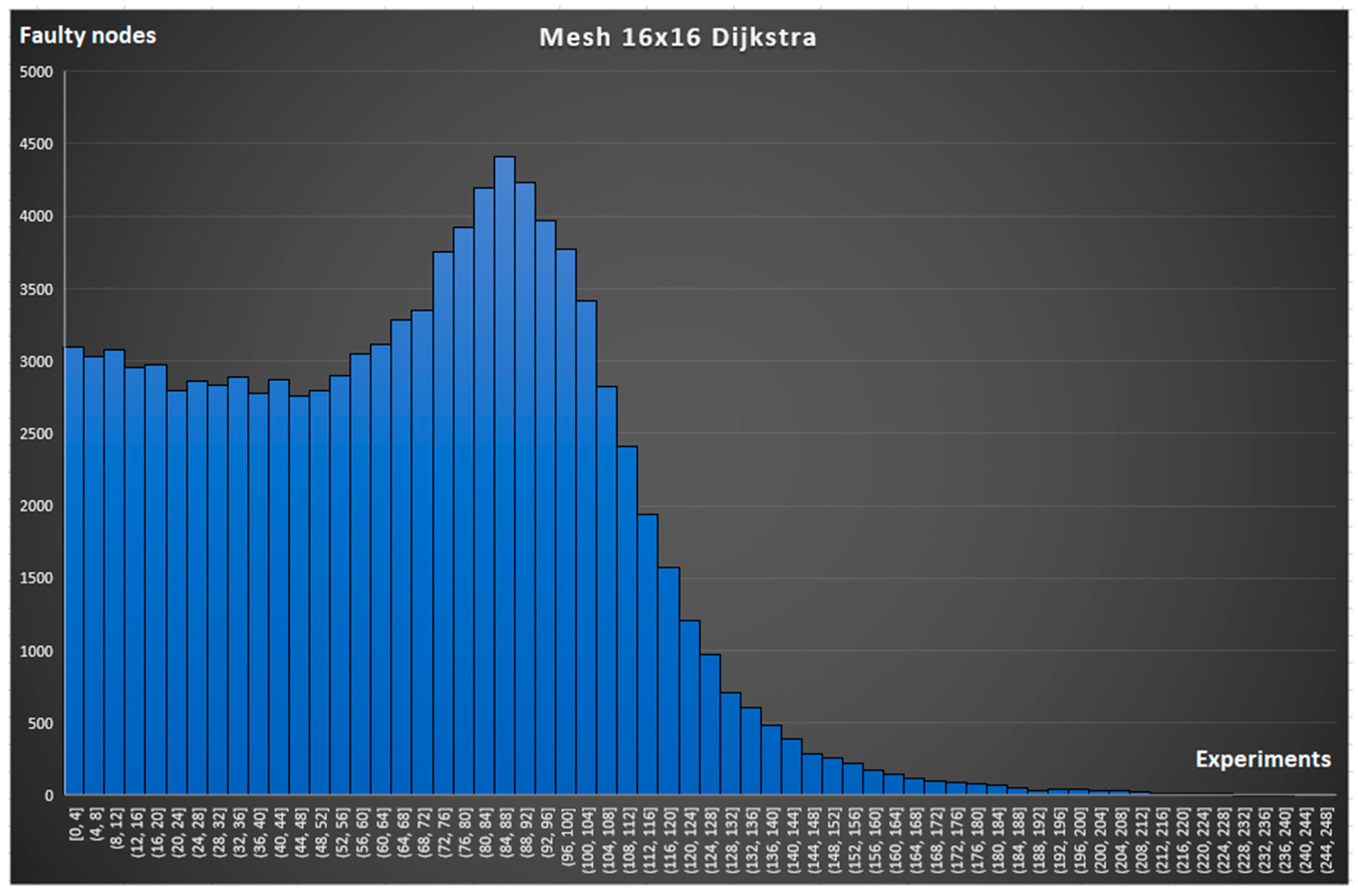
The graphs in
Figure 12 and
Figure 13 were obtained for mesh16x16 topology for the same routing strategies [
37].
It follows from the nature of the graphs that the more to the right on the
X-axis the peak of the graph is, the better the network copes with the occurrence of node faults. This is confirmed by the expected result that with ideal routing, broken connections occur less often (see a comparison of the graph in
Figure 10 and
Figure 11 and the graph in
Figure 12 and
Figure 13). A comparison of the graphs in
Figure 10 and
Figure 12 and the graph in
Figure 11 and
Figure 13 demonstrates the advantage of the circulant topology over the mesh topology.
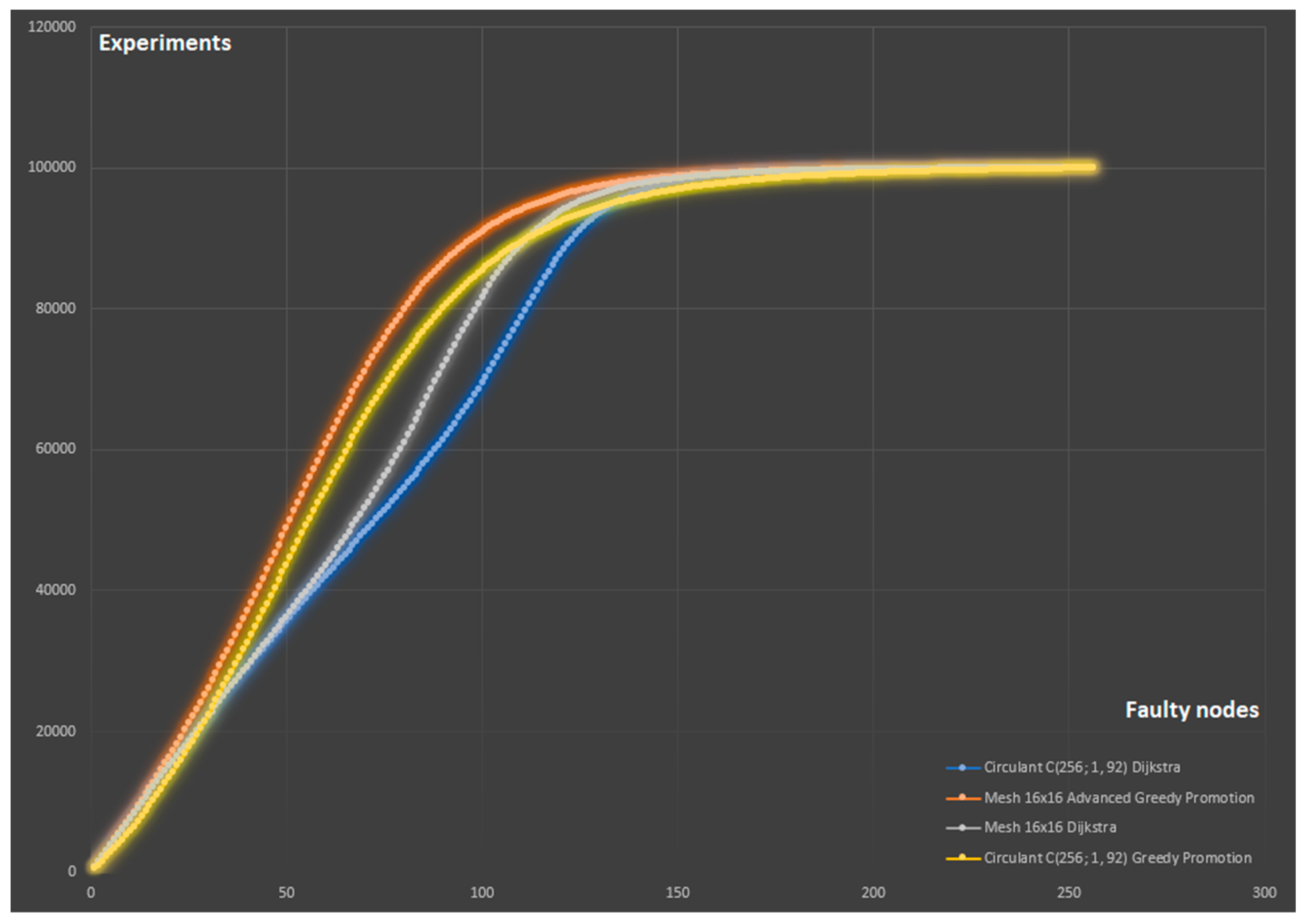
For a more objective and visual comparison, we combined the simulation results into one common graph in
Figure 14. It displays the number of experiments in which a connection break occurred when the nodes, the number of which is less than or equal to the value on the
X-axis, were faulty. It follows from the nature of the graph that the smaller the area under the corresponding curve, the more fault-tolerant the network. Thus, it is possible to compare different configurations of topologies and routing strategies with each other. The Greedy Promotion Algorithm is 6% worse than the ideal algorithm for mesh16x16 and 5% worse for
, which is expected and is a good result since it is not possible to implement the ideal routing algorithm in NoC conditions. We can also conclude that the use of circulant topology gave 4.3% (Greedy Promotion) and 3.6% (Dijkstra) better results compared to 2D mesh.
7. Conclusions
In this paper, we compare two topologies for NoCs: 2D mesh and the circulant. In order to conduct a full-fledged comparison, virtual coordinates of the nodes for the circulant topology were proposed, and the principle of greedy promotion used to build a route was formulated. As coordinates for the circulant, integer coefficients of the expansion of the node number in terms of generator lengths are chosen.
The first feature used for comparison is the diameter of the resulting network for different topologies. It turned out that with an equal number of nodes, the diameter of the circulant is two times smaller than the diameter of the 2D mesh. This is due to the large number of symmetries for the circulant, which leave the set of nodes unchanged.
The article also compares the resilience of communications with an increase in the percentage of faulty nodes. We evaluated the behavior of the network under load and simulated a situation in which it would be impossible to connect two arbitrary nodes. During the simulation, the network load was found, after which broken connections arose in the network. Simulation confirms the advantages of the circulant topology.
The study made it possible to formulate a methodology for calculating optimal network configurations. Dense network states are defined when all neighborhoods are filled with nodes and the network has the smallest diameter. At the same time, further studies are required to find the lengths of the circulant generators to uniformly fill all the neighborhoods. It is also necessary to investigate whether the configurations of nodes with the smallest diameter are the configurations with the smallest MPL between nodes. We also formulated the rules for constructing the shortest routes between the two nodes based on virtual coordinates.


