Article

Investigation of Perturbations Arising from Temperature Shock with a Symmetrical Arrangement of Flexible Elements of a Small Spacecraft

1
Department “Automation and Control”, Penza State Technological University, Baydukova Passage/st. Gagarina, 1a/11, Penza 440039, Russia
2
Department of Space Engineering, Institute of Aviation and Rocket and Space Technology, Samara National Research University, st. Moscow highway, 34, Samara 443086, Russia
*
Author to whom correspondence should be addressed.
Symmetry 2023, 15(7), 1331; https://doi.org/10.3390/sym15071331
Submission received: 4 June 2023 / Revised: 20 June 2023 / Accepted: 27 June 2023 / Published: 29 June 2023
(This article belongs to the Special Issue Symmetry and Asymmetry in Complex Technical Systems)

Abstract

:
This paper investigates the effect of a temperature shock on a small spacecraft with symmetrically arranged flexible elements. A two-dimensional thermoelasticity problem is posed. The disturbing effect of temperature shock on a small spacecraft has been determined. The assessment of the main disturbing factors arising from the temperature shock of flexible elements of a small spacecraft was carried out. Approximate dependences were obtained for the components of the displacement vector of the flexible element points. Numerical simulation was carried out for the symmetric scheme of the small spacecraft with two and four flexible elements. The dependence of the inertia force on temperature shock for the simulated small spacecraft at various initial deflections of the flexible element was constructed. Conclusions were drawn about the significance of the temperature shock influence on the dynamics of a small spacecraft. The results obtained were compared with the results of other studies and can be used in solving problems of remote sensing of the Earth and the implementation of gravity-sensitive processes on board small spacecraft.

1. Introduction

Small spacecraft are playing an increasingly important role in space missions [1,2,3]. Despite their small size, they are modern complex technical systems. However, it is necessary to conduct additional research to use them effectively. This is primarily due to the fact that the mass fraction of flexible elements in the total mass of the small spacecraft is higher than that of other space technology [4,5]. This situation is explained by the requirements for the electricity generated by solar panels, which is necessary for the effective functioning of the target equipment of the small spacecraft [6,7]. Some small spacecraft do not have flexible solar panels and are used in uncontrolled motion [7,8,9,10]. The controlled motion of small spacecraft has a number of features due to the more significant influence of flexible elements on this motion [11,12,13]. Therefore, in addition to the traditional disturbances from solar panels associated with their natural oscillations, it is necessary to take into account other factors [14,15,16]. One of these factors is the temperature shock [17,18,19,20,21]. Temperature shock occurs when the spacecraft enters the Earth’s shadow and exits it during its orbital motion. According to the research carried out in [22], it has a significant effect only on small spacecraft motion. Therefore, it is necessary to take it into account when performing individual target tasks. Examples of such tasks are remote sensing of the Earth from space [23,24,25] or implementation of gravity-sensitive technological processes on board small spacecraft [26,27,28].
Thus, it is necessary to meet the orientation requirements for remote sensing of the Earth [29,30,31]. These requirements are becoming increasingly high over time due to the increase in remote sensing resolution [32,33]. In many works, for example [34,35], the authors indicate that temperature shock can violate the orientation requirements. This is especially true of the requirements for the angular velocity of the small spacecraft rotation at the time of remote sensing of the Earth [36,37].
An even more complicated situation arises when gravity-sensitive processes are implemented on board the spacecraft. They impose high requirements on the level of micro-accelerations in the working area of technological equipment [38,39,40]. Studies [41,42,43] show that temperature shock can significantly violate these requirements. Therefore, for the effective use of small spacecraft in the field of space technologies, it is necessary not only to study and evaluate the temperature shock effect but also to develop algorithms to neutralize this influence using the executive bodies of the orientation and motion control system of the small spacecraft [44].
Considering the prospects for the development of space technology, then the use of new types of solar panels, for example, ROSA [45,46,47], poses the problem of temperature shock more widely than is done in this review. Experiments on the International Space Station with ROSA solar panels have shown that the problem of small spacecraft controllability becomes acute when using them. The use of ROSA panels is extremely promising for small spacecraft due to the reduced weight of the structure when using them. However, the controllability of the spacecraft is also significantly reduced due to thermal fluctuations [19,23] caused by temperature shock.
Reference [44] presents an algorithm for linear and piecewise linear control of the small spacecraft to neutralize temperature shock. Reference [22] presents an analysis of the disturbing factors significant in temperature shock. Both of these works are devoted to the research of a small spacecraft with one flexible element. An example of such a spacecraft is Earth Observing One (EO-1) [48]. However, small spacecraft with an even number of flexible elements are more common. For example, the Aist-2D small Earth remote sensing spacecraft has two flexible elements in the form of solar panels [24,49]. Theoretical studies [3] have shown that in the case of an even number of flexible elements, some of the perturbations studied in [22] are mutually compensated. Therefore, the algorithms presented in [44] cannot be effectively used for such small spacecraft. This paper aims to study the disturbing effect of temperature shock on small spacecraft with a symmetrical arrangement of flexible elements for the subsequent development of effective control algorithms that neutralize temperature shock.
In other areas, the considered problem is also important. For example, the study of parameters affecting the characteristics of sound transmission by a two-layer multilayer magnetoelectroelastic plate with transverse layers based on a viscoelastic medium under high-temperature conditions [50] shows the importance of the problem being solved. Thus, the results of the work can be applied in other areas.
This paper has the following structure: the thermoelasticity problem is considered, within which approximate analytical dependences are obtained. They differ from those obtained earlier because they take into account various initial deflections of the flexible element. Then, the assessment of disturbing factors from temperature shock is carried out. Unlike previous works, it also takes into account various forms of initial deflection of the flexible element. Finally, numerical simulation is carried out for the schemes of two small spacecraft. They have two and four flexible elements, respectively. Conclusions are drawn about the effect of temperature shock on the dynamics of small spacecraft orbital motion.

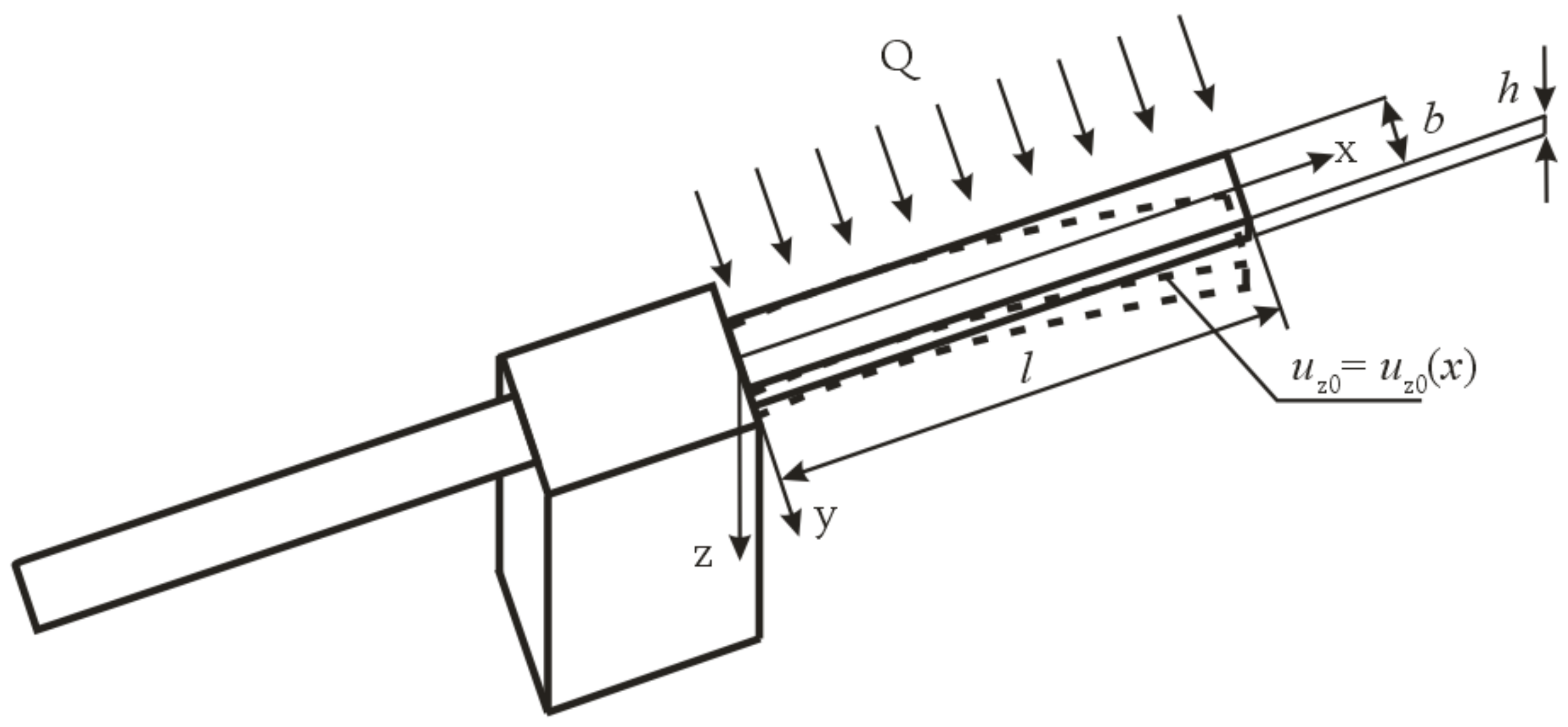
2. The Problem of Thermoelasticity

The one-dimensional thermoelasticity problem is considered in [3,44]. It represents the most dangerous scenario in terms of the intensity of the temperature shock impact on the movement of the small spacecraft [51]. This is enough to assess the need to take into account the temperature shock. However, for the development of a control algorithm, where various scenarios should be provided, such a statement is not enough. Therefore, in this paper, we use the two-dimensional formulation of the thermoelasticity problem described in [25,34,52]. It is different from the one-dimensional one because the initial deformed state of the solar panel at the time of the temperature shock is taken into account. At the same time, the scenario for implementing the one-dimensional task is also included in this approach as a special case. Figure 1 shows a scheme of the symmetrical small spacecraft for the temperature shock studies. The dotted line in Figure 1 indicates the deformed initial position of the flexible element. The solid line shows its undeformed flat position.
Let us assume that the initial deflections of both elastic elements coincide and all simplifying assumptions for the symmetric formulation of the thermoelasticity problem described in [3] are valid.
Mathematically, the two-dimensional thermoelasticity problem is represented by the following system of equations [25,34,52]:
T ( x , z , t ) t = a 2 2 T ( x , z , t ) x 2 + 2 T ( x , z , t ) z 2 , 0 x l , 0 z h , t > 0 ; D h 4 u z x , t x 4 + ρ h 2 u z x , t t 2 = 2 μ α 0 h 2 T ( x , z , t ) z + z 2 T ( x , z , t ) z 2 d z + + 2 u z 0 x , t x 2 σ x z x , t , 0 x l , z = h 2 , t > 0 ; λ T ( x , z , t ) n = Q ε σ T 4 ( x , h , t ) T C 4 , 0 x l , z = h , t > 0 ; λ T ( x , z , t ) n = ε σ T 4 ( x , 0 , t ) T C 4 , 0 x l , z = 0 , t > 0 ; T ( x , z , 0 ) = T 0 = c o n s t , 0 x l , 0 z h , t = 0 ; u z 0 , t = 0 , x = 0 , t > 0 ; u z x , t x = 0 , x = 0 , t > 0 ; 2 u z x , t x 2 = 0 , x = l , t > 0 ; 3 u z x , t x 3 = 0 , x = l , t > 0 ; u z x , 0 = u z 0 x , 0 , 0 x l , t = 0 .
where a is the coefficient of temperature conductivity; h is the thickness of the flexible element; u z = u z x ,   t —the deflection of the flexible element points in the direction of the z-axis; u z 0 = u z 0 x ,   0 —the initial deflection of the flexible element points in the direction of the z-axis; ρ is the density of the flexible element; D is the cylindrical rigidity of the flexible element for bending; l is the length of the flexible element; λ is the coefficient of thermal conductivity; ε is the degree of blackness of the flexible element material; σ is the Stefan–Boltzmann constant; n is the unit vector of the normal to the surface element; and σxz is the component of the stress tensor.
The first equation of System (1) is a classical equation of two-dimensional thermal conductivity when the temperature field has the following form: T = T ( x ,   z ,   t ) . At the same time, Fourier’s law is valid.
In the second equation of System (1), it is assumed that the deflection in the framework of the two-dimensional problem can be represented as u z = u z x ,   t [53]. It is a Sophie Germain equation for thin plates [52,54]. Its satisfaction is required only in the middle of the plate within the framework of this statement. Because the plate is thin, this requirement is quite enough.
The third and fourth equations of System (1) represent the boundary conditions of the third kind for the two-dimensional model of thermal conductivity. They assume the neglect of the heat exchange through the side surface of the flexible element because its thickness is small. They are written for the general case of arbitrary deflection when the unit vector of the normal to the surface element n does not coincide with the direction of the z-axis, as it was in the symmetric formulation [3] for the one-dimensional thermoelasticity problem.
The fifth equation of System (1) describes a uniform temperature field of the flexible element at the time of the temperature shock onset and represents the initial condition for the thermal conductivity problem. The first, third, fourth, and fifth equations fully describe the two-dimensional problem of thermal conductivity and allow us to determine the temperature field of the flexible element at any time.
The sixth and seventh equations of System (1) describe the geometric boundary conditions of a rigidly fixed edge of the flexible element (Figure 1). They determine the absence of deflections and angles of rotation in the seal.
The eighth and ninth equations of System (1) represent static boundary conditions and determine the absence of forces and moments on the free edge of the flexible element. A simplified representation of these boundary conditions is combined by the form of the deflection function u z = u z x ,   t , which does not depend on the y coordinate.
The tenth and last equation of System (1) defines the function of the initial deflections. When u z 0 = u z 0 x ,   0 0 and the incident heat flux is perpendicular to the plate surface, the two-dimensional thermoelasticity problem degenerates into the one-dimensional problem [3]. The second, sixth, seventh, eighth, ninth, and tenth equations of System (1) completely define the two-dimensional problem of thermoelasticity and allow, with a known temperature field, to obtain a field of deflections of the flexible element points at an arbitrary time.
Thus, the initial boundary value problem of thermoelasticity has been set, which allows us to assess the main disturbances caused by the temperature shock.

3. Evaluation of Disturbing Factors

To assess the disturbing factors, let us use the studies conducted in [3,22,53]. Let the vector of displacements of the flexible element points under the temperature shock have the general form of u u x ,   u y ,   u z . Studies [25,52] show that only the deflections of points of the flexible element u z = u z x ,   t can be taken into account when evaluating perturbations, because the other components of the displacement vector are negligible compared with deflections. Thus, numerical modeling in [25] shows that the component of the displacement vector u y = u y x ,   y ,   t is more than two orders of magnitude smaller than the deflection. Let us consider the component of the displacement vector u x = u x x ,   t . It is shown in [8,22] that the points with coordinates l / 2 x l should move along the x-axis. Let us write down the equilibrium equation for these points [3,22]:
N = E S ε x x α T x ,     z ,     t T 0 x ,     z ,     0     d S
where d S = d y   d z is an infinitesimal element of the cross section of the flexible element; ε x x is an element of the strain tensor; α is the coefficient of thermal expansion; E is Young’s modulus; and N is the internal longitudinal force arising in the infinitesimal element of the cross section of the flexible element.
With the free expansion of the flexible element:
N = 0 ,   l 2 x l
Therefore, instead of (2), we have
ε x x = α T x ,     z ,     t T 0 x ,     z ,     0 ,     l 2 x l ,     z = h 2 ,     t > 0
Equation (4), as well as the second equation of System (1), is considered valid for the median surface of the plate. This is quite enough for a thin plate. We have a displacement estimation [55]:
u x x = α T x ,     z ,     t T 0 x ,     z ,     0 ,     l 2 x l ,     z = h 2 ,     t > 0
After integrating (5), we have
u x = α T x ,     z ,     t T 0 x ,     z ,     0 d x ,     l 2 x l ,     z = h 2 ,     t > 0
With a maximum temperature difference of 100 K and a coefficient of thermal expansion of α = 2.6 · 10 6   K 1 , the maximum ux values are about 0.13 mm. This is more than an order of magnitude lower than the deflection values (about 3 mm [25]). Therefore, it is sufficient to take into account only deflections that are much more significant than other components of the displacement vector to neutralize the temperature shock.
It was noted in [3] that with the symmetrical formulation (symmetrical arrangement of flexible elements), only one disturbing factor from the temperature shock is unbalanced. This is the force of inertia in the direction of the z-axis [3]:
Φ z t = k 0 m 1 u ¨ z x ,   t   d m = k m 1 l 0 l u ¨ z x ,     t   d x
where k is the number of flexible elements; m1 is the mass of one flexible element; and u ¨ z ( x ,   t ) is the second total derivative of the deflection with respect to time.
Let us use the expression obtained in [54] for deflections in the framework of the two-dimensional model of thermoelasticity (Expression (16) [54]):
u z ( x ,   t ) = A t t + a x 4 4 l x 3 + 6 l 2 x 2 + u z 0 ( x ,   0 ) ,   0 x l ,     t > 0
where a and A are some positive constants [54].
In [3], it was assumed that u ¨ z ( x ,   t ) 2 u z ( x ,   t ) t 2 . In this case, the inertia force (7) does not depend on the initial deflection. It coincides with a similar force for the one-dimensional formulation of the thermoelasticity problem [22]. Let us consider u ¨ z ( x ,   t ) in a more general way:
u ¨ z ( x ,   t ) = 2 u z ( x ,   t ) x 2 u ¨ x ( x ,   t ) + 2 2 u z ( x ,   t ) x   t u ˙ z ( x ,   t ) + 2 u z ( x ,   t ) t 2
Taking into account (8), we have
u ¨ z ( x ,   t ) = 12 A t t + a x 2 2 l x + l 2 + 2 u z 0 ( x ,   0 ) x 2 u ¨ x ( x ,   t ) + + 8 a t + a 2 x 3 3 l x 2 + 3 l 2 x u ˙ z ( x ,   t ) 2 a t + a 3 x 4 4 l x 3 + 6 l 2 x 2 ,   0 x l ,   t > 0 .
Analysis of Expression (10) shows that acceleration ( u ¨ z ( x ,   t ) ) is not necessarily opposite to the deflection ( u z ( x ,   t ) ) itself, as in the case when u ¨ z ( x ,   t ) 2 u z ( x ,   t ) t 2 . It is more general. In this case, the inertia force (7) depends on the initial deflection, because the first term of the right part (10) contains the second derivative of the initial deflection function ( u z 0 = u z 0 x ,   0 ).
Let us use the approximation of the temperature field proposed in [54]:
T ( x ,   z ,   t ) = C z t t + a M x + T 0 ,   0 x l ,   0 z h ,   t > 0
where C and M are some positive constants [54].
Then, considering z = h/2 (the median surface of the plate), we obtain expressions for u ˙ x ( x ,   t ) and u ¨ x ( x ,   t ) :
u ˙ x ( x ,   t ) = u x x d x d t + u x t
We believe that u ˙ x ( x ,   t ) d x d t . Therefore, we have
u ˙ x ( x ,   t ) = 1 1 u x x u x t
Considering Expressions (6) and (11), we obtain
u x x = α C t t + a h 2 M x
u x t = α   C a t + a 2 h 2 x
Substituting (14) and (15) into (13), we get
u ˙ x ( x ,   t ) = α C a h x 2 α C t t + a h 2 M x t + a 2
The second total derivative has the following form:
u ¨ x ( x ,   t ) = u ˙ x x d x d t + u ˙ x t
Then
u ˙ x x = α   C a h t + a 2 2 α   C t t + a h 2 α   C t t + a h 2 M x 2
u ˙ x t = α   C a h x t + a 3 2 α   C t t + a h 2 M x α   C a h t + a 2 α   C t t + a h 2 M x 2 2
Substituting (18) and (19) into (17), we get
u ¨ x = α   C a h x t + a 3 2 α   C t t + a h 2 M x α   C a h t + a 2 α   C t t + a h 2 M x 2 α   C t t + a h 2 α   C t t + a h 2 M x + 1 2 .
It is possible to obtain estimations of the disturbing effect of temperature shock on the small spacecraft with the symmetrical scheme of flexible elements by substituting (16) and (20) into (10) at first, and after that (10) into (7).

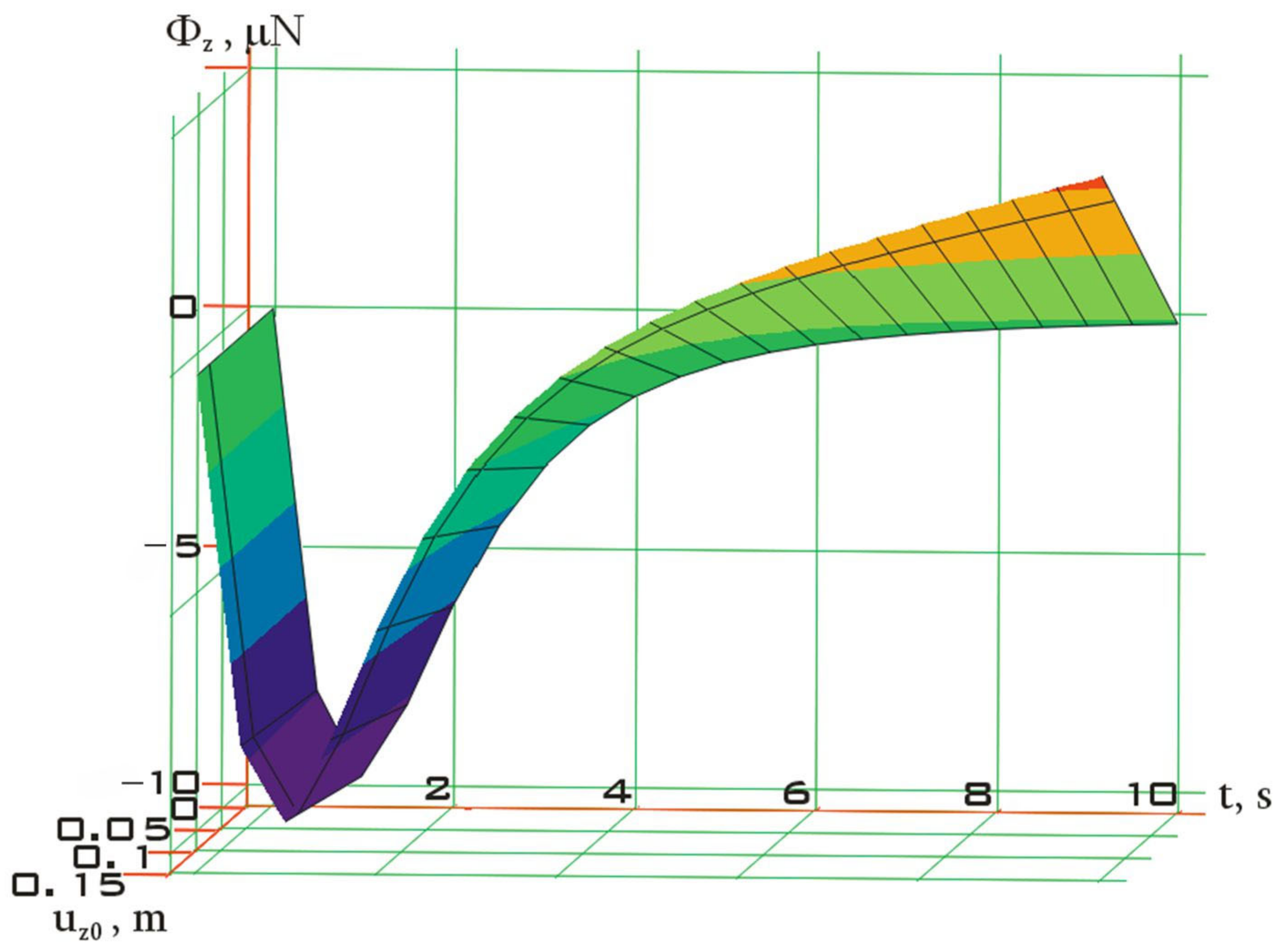
4. Numerical Modeling

Let us conduct numerical modeling and consider the small spacecraft model, the scheme of which is shown in Figure 1, and the main characteristics are given in Table 1 [3]. This allows us to compare the simulation results with the symmetric formulation in [3].
If the initial deflection is represented by the expression in Table 1, the results shown in Figure 2 are obtained.
uz0 in Figure 2 refers to the maximum deviation of the free edge of the flexible element at the initial deflection. More significant values of uz0 than shown in Figure 2 can cause a stability loss of the flexible element [34,53] and have not been considered in this work.
The analysis of Figure 2 shows its fundamental similarity with the results obtained in [3] without taking into account the initial deflection (Figure 9 in [3]). In a wider range of initial deflections, the dependence of the inertia force on the initial deflection would probably be more noticeable. However, in this case, there is a stability loss of the flexible element. Therefore, this comparison is incorrect. It should also be noted that with the linear dependence of uz0 on x, the pattern described in [3] is observed because the dependence of the inertia force on the initial deflection is viewed if the second partial derivative of uz0 with respect to x is different from zero.
Let us consider another spacecraft, the simulation of which was performed in [34]. However, in [34], a scheme with one flexible element was considered. The design of this spacecraft provides four flexible elements (Figure 3) [3].
The main characteristics of the simulated spacecraft are given in Table 2 [34]. This allows us to compare the simulation results with the results presented in [34].
In this case, we get the results shown in Figure 4.
The analysis of Figure 4 shows its fundamental similarity with the results obtained in [34] without taking into account the initial deflection in the framework of the one-dimensional thermoelasticity problem (Figure 5 in [34]). However, due to the greater length of the flexible elements in this case, it was possible to realize larger values of the initial deflection without a stability loss than in the previous case (Figure 2). Here, the dependence of the inertia force on the initial deflection is more clearly seen. The potential energy of the initial deformation contributes to the achievement of the large values of inertia force after the initial stage of the temperature shock. The initial stage of the inertia force dynamics of both numerical simulation examples is a more rapid dynamic phenomenon and practically does not depend on the initial deflection (Figure 2 and Figure 4).

5. Conclusions

Thus, as a result of the conducted studies, estimations of the disturbing effect of temperature shock on a small spacecraft were obtained. This effect, in the case of a symmetrical arrangement of flexible elements, is represented as a force of inertia from the accelerated movement of the flexible element points. The other disturbing factors are mutually compensated due to symmetry. The numerical simulation carried out for two schemes of small spacecraft with two and four flexible elements showed good convergence of the results with other authors. The obtained results can be used in the development of algorithms for the operation of the executive bodies of the small spacecraft motion control system to neutralize the influence of the temperature shock. This may be relevant when solving problems of remote sensing of the Earth, as well as for the implementation of gravity-sensitive processes on board a small spacecraft.

Author Contributions

Conceptualization, A.B.; methodology, A.B.; software, D.O. and A.B.; validation, D.O. and A.B.; formal analysis, D.O. and A.B.; investigation, D.O. and A.B.; resources, D.O. and A.B.; data curation, D.O. and A.B.; writing—original draft preparation, D.O. and A.B.; writing—review and editing, D.O. and A.B.; visualization, D.O.; supervision, D.O. and A.B.; project administration, D.O.; funding acquisition, D.O. and A.B. All authors have read and agreed to the published version of the manuscript.

Funding

This research was funded by the Russian Science Foundation grant number 23-29-00207.

Institutional Review Board Statement

Not applicable.

Informed Consent Statement

Not applicable.

Data Availability Statement

Not applicable.

Acknowledgments

This study was supported by the Russian Science Foundation (Project No. 23-29-00207 (https://rscf.ru/project/23-29-00207/).

Conflicts of Interest

The authors declare no conflict of interest.

References

  1. Ovchinnikov, M.Y.; Guerman, A.D.; Mashtakov, Y.V.; Roldugin, D.S. Mathematical Modeling of the Dynamics of a Low-Flying Spacecraft with a Ramjet Electric Propulsion Engine. Math. Model. Comput. Simul. 2022, 14, 452–465. [Google Scholar] [CrossRef]
  2. Makarov, S.B.; Liu, M.; Ovsyannikova, A.S.; Zavjalov, S.V.; Lavrenyuk, I.; Xue, W.; Xu, Y. A Reduction of Peak-to-Average Power Ratio Based Faster-Than-Nyquist Quadrature Signals for Satellite Communication. Symmetry 2021, 13, 346. [Google Scholar] [CrossRef]
  3. Sedelnikov, A.; Orlov, D.; Serdakova, V.; Nikolaeva, A. The Symmetric Formulation of the Temperature Shock Problem for a Small Spacecraft with Two Elastic Elements. Symmetry 2023, 15, 172. [Google Scholar] [CrossRef]
  4. Taneeva, A.S. The formation of the target function in the design of a small spacecraft for technological purposes. J. Phys. Conf. Ser. 2021, 1901, 12026. [Google Scholar] [CrossRef]
  5. Anshakov, G.P.; Belousov, A.I.; Sedel’nikov, A.V.; Gorozhankina, A.S. Efficiency Estimation of Electrothermal Thrusters Use in the Control System of the Technological Spacecraft Motion. Russ. Aeronaut. 2018, 61, 347–354. [Google Scholar] [CrossRef]
  6. Anttu, N. Absorption of Light in Finite Semiconductor Nanowire Arrays and the Effect of Missing Nanowires. Symmetry 2021, 13, 1654. [Google Scholar] [CrossRef]
  7. Sedelnikov, A.V.; Potienko, K. Analysis of Reduction of Controllability of Spacecraft During Conducting of Active Control Over Microaccelerations. Int. Rev. Aerosp. Eng. 2017, 10, 160. [Google Scholar] [CrossRef]
  8. Bormotov, A.; Orlov, D.; Bratkova, M. Modeling the deformation of an elastic element of a small spacecraft in its plane during temperature shock. E3S Web Conf. 2023, 376, 1085. [Google Scholar] [CrossRef]
  9. Sedelnikov, A.V.; Salmin, V.V. Modeling the disturbing effect on the aist small spacecraft based on the measurements data. Sci. Rep. 2022, 12, 1300. [Google Scholar] [CrossRef]
  10. Taneeva, A.S.; Lukyanchik, V.V.; Khnyryova, E.S. Modeling the Dependence of the Specific Impulse on the Temperature of the Heater of an Electrothermal Micro-Motor Based on the Results of Its Tests. J. Phys. Conf. Ser. 2021, 2096, 12059. [Google Scholar] [CrossRef]
  11. Orlov, D.; Serdakova, V.; Evtushenko, M.; Khnyryova, E.; Nikolaeva, A. Investigating the Features of Various Plate Models Under the Thermal Shock in the ANSYS Package. In Proceedings of the XV International Scientific Conference “INTERAGROMASH 2022”, Rostov-on-Don, Russia, 25–27 May 2022; Lecture Notes in Networks and Systems 2023. Volume 574, pp. 3085–3093. [Google Scholar] [CrossRef]
  12. Sedelnikov, A.V. Evaluation of the level of microaccelerations on-board of a small satellite caused by a collision of a space debris particle with a solar panel. Jordan J. Mech. Ind. Eng. 2017, 11, 121–127. [Google Scholar]
  13. Ovchinnikov, M.Y.; Tkachev, S.S.; Shestopyorov, A.I. Mathematical Model of a Satellite with an Arbitrary Number of Flexible Appendages. Math. Model. Comput. Simul. 2021, 13, 638–647. [Google Scholar] [CrossRef]
  14. Ibrahim, A.; Modi, V. A formulation for studying dynamics of N connected flexible deployable members. Acta Astronaut. 1987, 16, 151–164. [Google Scholar] [CrossRef]
  15. Sedel’nikov, A.V. Fractal assessment of microaccelerations at weak damping of natural oscillation in spacecraft elastic elements. II. Russ. Aeronaut. 2007, 50, 322–325. [Google Scholar] [CrossRef]
  16. Russkikh, S.V.; Shklyurchuk, F.N. Nonlinear Oscillations of Elastic Solar Panels of a Spacecraft at Finite Turn by Roll. Mech. Solids 2018, 53, 147–155. [Google Scholar] [CrossRef]
  17. Kartashov, E.M. Analytical Methods of Solution of Boundary-Value Problems of Nonstationary Heat Conduction in Regions with Moving Boundaries. J. Eng. Phys. Thermophys. 2001, 74, 498–536. [Google Scholar] [CrossRef]
  18. Sedelnikov, A.; Serdakova, V.V.; Khnyryova, E.S. Construction of the Criterion for Using a Two-dimensional Thermal Conductivity Model to Describe the Stress–strain State of a Thin Plate Under the Thermal Shock. Microgravity Sci. Technol. 2021, 33, 65. [Google Scholar] [CrossRef]
  19. Shen, Z.; Tian, Q.; Liu, X.; Hu, G. Thermally induced vibrations of flexible beams using Absolute Nodal Coordinate Formulation. Aerosp. Sci. Technol. 2013, 29, 386–393. [Google Scholar] [CrossRef]
  20. Tarasov, D.; Konovalov, V.; Zaitsev, V.; Rodionov, Y. Mathematical modeling of the stress-strain state of flexible threads with regard to plastic deformations. J. Phys. Conf. Ser. 2018, 1084, 12008. [Google Scholar] [CrossRef]
  21. Tarasov, D.; Konovalov, V.; Zaitsev, V.; Rodionov, Y. Mathematical modeling of deformations of flexible threads under their dynamic loading in the zone of material plasticity. J. Phys. Conf. Ser. 2019, 1278, 12014. [Google Scholar] [CrossRef] [Green Version]
  22. Sedelnikov, A.V.; Orlov, D.I. Analysis of the Significance of the Influence of Various Components of the Disturbance from a Temperature Shock on the Level of Microaccelerations in the Internal Environment of a Small Spacecraft. Microgravity Sci. Technol. 2021, 33, 22. [Google Scholar] [CrossRef]
  23. Johnston, J.D.; Thornton, E.A. Thermally induced attitude dynamics of a spacecraft with a flexible appendage. J. Guid. Control Dyn. 1998, 21, 581–587. [Google Scholar] [CrossRef]
  24. Kirilin, A.N.; Akhmetov, R.N.; Shakhmatov, E.V.; Tkachenko, S.I.; Baklanov, A.I.; Salmin, V.V.; Semkin, N.D.; Tkachenko, I.S.; Goryachkin, O.V. Experimental Technological Small Spacecraft “Aist–2D”; Publishing House of the Samara Scientific Center of the Russian Academy of Sciences: Samara, Russia, 2017; p. 324. [Google Scholar]
  25. Sedelnikov, A.V.; Orlov, D.I.; Serdakova, V.V.; Nikolaeva, A.S. Investigation of the Stress-Strain State of a Rectangular Plate after a Temperature Shock. Mathematics 2023, 11, 638. [Google Scholar] [CrossRef]
  26. Lyubimova, T.; Rybkin, K.; Fattalov, O.; Kuchinskiy, M.; Kozlov, M. Investigation of Generation and Dynamics of Microbubbles in the Solutions of Anionic Surfactant (SDS). Microgravity Sci. Technol. 2022, 34, 74. [Google Scholar] [CrossRef]
  27. Wang, A.; Wang, S.; Xia, H.; Ma, G. Dynamic Modeling and Control for a Double-State Microgravity Vibration Isolation System. Microgravity Sci. Technol. 2023, 35, 9. [Google Scholar] [CrossRef]
  28. Anshakov, G.P.; Belousov, A.I.; Sedel’nikov, A.V. The problem of estimating microaccelerations aboard Foton-M4 spacecraft. Russ. Aeronaut. 2017, 60, 83–89. [Google Scholar] [CrossRef]
  29. Zhu, Q.; Jiang, W.; Zhu, Y.; Li, L. Geometric Accuracy Improvement Method for High-Resolution Optical Satellite Remote Sensing Imagery Combining Multi-Temporal SAR Imagery and GLAS Data. Remote Sens. 2020, 12, 568. [Google Scholar] [CrossRef] [Green Version]
  30. Jiang, Y.; Wang, J.; Zhang, L.; Zhang, G.; Li, X.; Wu, J. Geometric Processing and Accuracy Verification of Zhuhai-1 Hyperspectral Satellites. Remote Sens. 2019, 11, 996. [Google Scholar] [CrossRef] [Green Version]
  31. Su, Z.; Zhong, X.; Zhang, G.; Li, Y.; He, X.; Wang, Q.; Wei, Z.; He, C.; Li, D. High Sensitive Night-time Light Imaging Camera Design and In-orbit Test of Luojia1-01 Satellite. Sensors 2019, 19, 797. [Google Scholar] [CrossRef] [PubMed] [Green Version]
  32. Sedelnikov, A.V. Algorithm for restoring information of current from solar panels of a small spacecraft prototype “Aist” with help of normality conditions. J. Aeronaut. Astronaut. Aviat. 2022, 54, 67–76. [Google Scholar]
  33. Long, T.; Jiao, W.; He, G.; Zhang, Z. A Fast and Reliable Matching Method for Automated Georeferencing of Remotely-Sensed Imagery. Remote Sens. 2016, 8, 56. [Google Scholar] [CrossRef] [Green Version]
  34. Sedelnikov, A.V.; Serdakova, V.V.; Glushkov, S.V.; Nikolaeva, A.S.; Evtushenko, M.A. Consideration of the Initial Deformation from Natural Oscillations of Large Elastic Elements of the Spacecraft When Assessing Microaccelerations from Thermal Shock Using a Two-dimensional Model of Thermal Conductivity. Microgravity Sci. Technol. 2022, 34, 22. [Google Scholar] [CrossRef]
  35. Johnston, J.D.; Thornton, E.A. Thermally Induced Dynamics of Satellite Solar Panels. J. Spacecr. Rocket. 2000, 37, 604–613. [Google Scholar] [CrossRef]
  36. Wang, W.; Zhu, Y.; Tang, Z.; Chen, Y.; Zhu, Z.; Sun, Y.; Zhou, C. Efficient Rotational Angular Velocity Estimation of Rotor Target via Modified Short-Time Fractional Fourier Transform. Remote Sens. 2021, 13, 1970. [Google Scholar] [CrossRef]
  37. Fasano, G.; Rufino, G.; Accardo, D.; Grassi, M. Satellite Angular Velocity Estimation Based on Star Images and Optical Flow Techniques. Sensors 2013, 13, 12771–12793. [Google Scholar] [CrossRef] [PubMed]
  38. S̆eta, B.; Dubert, D.; Prats, M.; Gavalda, J.; Massons, J.; Bou-Ali, M.; Ruiz, X.; Shevtsova, V. Transitions between nonlinear regimes in melting and liquid bridges in microgravity. Int. J. Heat Mass Transf. 2022, 193, 122984. [Google Scholar] [CrossRef]
  39. Sedelnikov, A.; Kireeva, A. Alternative solutions to increase the duration of microgravity calm period on board the space laboratory. Acta Astronaut. 2011, 69, 480–484. [Google Scholar] [CrossRef]
  40. Abrashkin, V.I.; Voronov, K.E.; Piyakov, I.V.; Puzin, Y.Y.; Sazonov, V.V.; Semkin, N.D.; Chebukov, S.Y. Rotational motion of Foton M-4. Cosm. Res. 2016, 54, 296–302. [Google Scholar] [CrossRef]
  41. Orlov, D.I. Modeling the temperature shock impact on the movement of a small technological spacecraft. AIP Conf. Proc. 2021, 2340, 50001. [Google Scholar] [CrossRef]
  42. Sedelnikov, A.V.; Eskina, E.V.; Taneeva, A.S.; Khnyryova, E.S.; Bratkova, M.E. The problem of ensuring and controlling microaccelerations in the internal environment of a small technological spacecraft. J. Curr. Sci. Technol. 2023, 13, 1–11. [Google Scholar]
  43. Shen, Z.; Hu, G. Thermally Induced Dynamics of a Spinning Spacecraft with an Axial Flexible Boom. J. Spacecr. Rocket. 2015, 52, 1503–1508. [Google Scholar] [CrossRef] [Green Version]
  44. Sedelnikov, A.V.; Orlov, D.I. Development of Control Algorithms for the Orbital Motion of a Small Technological Spacecraft with a Shadow Portion of the Orbit. Microgravity Sci. Technol. 2020, 32, 941–951. [Google Scholar] [CrossRef]
  45. Chamberlain, M.K.; Kiefer, S.H.; LaPointe, M.; LaCorte, P. On-orbit flight testing of the Roll-Out Solar Array. Acta Astronaut. 2020, 179, 407–414. [Google Scholar] [CrossRef]
  46. Banik, J.; Kiefer, S.; LaPointe, M.; LaCorte, P. On-orbit validation of the roll-out solar array. In Proceedings of the 2018 IEEE Aerospace Conference, Big Sky, MT, USA, 3–10 March 2018. [Google Scholar] [CrossRef]
  47. Hoang, B.; Spence, B.; White, S.; Spence, B.; Kiefer, S. Commercialization of deployable space systems’ roll-out solar array (ROSA) technology for Space Systems Loral (SSL) solar arrays. In Proceedings of the 2016 IEEE Aerospace Conference, Big Sky, MT, USA, 5–12 March 2016. [Google Scholar]
  48. Middleton, E.M.; Ungar, S.G.; Mandl, D.J.; Ong, L.; Frye, S.W.; Campbell, P.E.; Landis, D.R.; Young, J.P.; Pollack, N.H. The Earth Observing One (EO-1) Satellite Mission: Over a Decade in Space. IEEE J. Select. Top. Appl. Earth Obs. Remote Sens. 2013, 6, 243–256. [Google Scholar] [CrossRef]
  49. Abrashkin, V.I.; Voronov, K.E.; Dorofeev, A.S.; Piyakov, A.V.; Puzin, Y.Y.; Sazonov, V.V.; Semkin, N.D.; Filippov, A.S.; Chebukov, S.Y. Detection of the Rotational Motion of the AIST-2D Small Spacecraft by Magnetic Measurements. Cosm. Res. 2019, 57, 48–60. [Google Scholar] [CrossRef]
  50. Refahati, N.; Jearsiripongkul, T.; Thongchom, C.; Saffari, P.R.; Keawsawasvong, S. Sound transmission loss of double-walled sandwich cross-ply layered magneto-electro-elastic plates under thermal environment. Sci. Rep. 2022, 12, 16621. [Google Scholar] [CrossRef] [PubMed]
  51. Sedelnikov, A.; Orlov, D.; Serdakova, V.; Nikolaeva, A.; Bratkova, M.; Ershova, V. The importance of a three-dimensional formulation of the thermal conductivity problem in assessing the effect of a temperature shock on the rotational motion of a small spacecraft. E3S Web Conf. 2023, 371, 03015. [Google Scholar] [CrossRef]
  52. Sedelnikov, A.; Serdakova, V.; Orlov, D.; Nikolaeva, A. Investigating the Temperature Shock of a Plate in the Framework of a Static Two-Dimensional Formulation of the Thermoelasticity Problem. Aerospace 2023, 10, 445. [Google Scholar] [CrossRef]
  53. Kawano, A. A uniqueness theorem for the determination of sources in the Germain–Lagrange plate equation. J. Math. Anal. Appl. 2013, 402, 191–200. [Google Scholar] [CrossRef]
  54. Sedelnikov, A.; Serdakova, V.; Nikolaeva, A. Method of Taking into Account Influence of Thermal Shock on Dynamics of Small Satellite and its Use in Analysis of Microaccelerations. Microgravity Sci. Technol. 2023, 35, 25. [Google Scholar] [CrossRef]
  55. Landau, L.D.; Lifshits, E.M. Theory of Elasticity; Nauka: Moscow, Russia, 1987; 248p. [Google Scholar]
Figure 1. The considered small spacecraft scheme.
Symmetry 15 01331 g001
Figure 2. The dependence of inertia force on temperature shock for the simulated small spacecraft.
Symmetry 15 01331 g002
Figure 3. The scheme of the “Vozvrat-MKA” spacecraft [3].
Symmetry 15 01331 g003
Figure 4. The dependence of inertia force on temperature shock for the simulated small spacecraft.
Symmetry 15 01331 g004
Table 1. Parameter values of the small spacecraft used in numerical simulation [3].
ParameterDesignationValueDimension
Spacecraft prototypeAist–2D [3]
Solar panel frame materialMA2
Mass of the spacecraftm530kg
Coefficient of thermal conductivity λ 96.3 W / ( m × K )
Stefan–Boltzmann constant σ 5.67 × 10 8 W / ( m 2 × K 4 )
Linear expansion coefficientα2.6 × 10⁻⁶K−1
External heat flux Q 01400 W / m 2
Vacuum temperature T C 3K
Initial temperature of the solar panel frame T ( x ,   y ,   z ,   0 ) 200K
Specific heatc1130.4 J / k g × K
Density ρ 1780 k g / m 3
Lame coefficient ΛΛ3 × 10¹⁰Pa
Lame coefficient νν1.6 × 10¹⁰Pa
Number of plate layersN3
Layer thickness Δ z 2mm
Solar panel lengthl2.5m
Poisson‘s coefficientμ0.3
Number of flexible elementsk2
Model parametersa1s
A10−4m−3
C200K/m
M3K/m
Initial deflectionuz0uz0 × 2/l2m
Table 2. Parameter values of the small spacecraft used in numerical simulation [35].
ParameterDesignationValueDimension
Number of elastic elementsi4
Weight of the small spacecraft body mK3t
Mass of the elastic elementm150kg
Length of the elastic elementl5m
Diagonal components of the inertia tensor in the principal bound coordinate systemIxx1t × m2
Iyy1.5
Izz1.5
The maximum distance of the internal environment point of the small spacecraft from its center of massr0.5m
Width of the elastic element b0.5m
Thickness of the elastic element h6mm
Material of the elastic element MA–2
Young’s modulusE42GPa
Thermal conductivity λ 96.3W/(m × K)
Thermal expansion coefficient α 2.6 × 10⁻⁴μm/(m × K)
External heat flux Q 1.4kW/m2
Vacuum temperature T C 3K
Initial temperature of the elastic element T ( x ,   z ,   0 ) 200K
Specific heatc1.13kJ/(kg × K)
Density ρ 1.78t/m3
Thickness of the elastic layer Δ z 1.5mm
Time step for calculating temperatures Δ t 0.04s
Model parametersa1s
A10−4m−3
C200K/m
M3K/m
Initial deflectionuz0uz0 × 2/l2m
Disclaimer/Publisher’s Note: The statements, opinions and data contained in all publications are solely those of the individual author(s) and contributor(s) and not of MDPI and/or the editor(s). MDPI and/or the editor(s) disclaim responsibility for any injury to people or property resulting from any ideas, methods, instructions or products referred to in the content.

