Article

Optical Torque Exerted on a Charged Sphere by a Polarized Bessel Beam

1
Center on Nanoenergy Research, Laboratory of Optoelectronic Materials & Detection Technology, Guangxi Key Laboratory for the Relativistic Astrophysics, School of Physical Science & Technology, Guangxi University, Nanning 530004, China
2
Department of Physics, University of North Florida, Jacksonville, FL 32224, USA
*
Authors to whom correspondence should be addressed.
Symmetry 2023, 15(1), 128; https://doi.org/10.3390/sym15010128
Submission received: 8 November 2022 / Revised: 19 December 2022 / Accepted: 28 December 2022 / Published: 2 January 2023
(This article belongs to the Special Issue Advance in the Applied Optics with Symmetry/Asymmetry)

Abstract

:
In the framework of generalized Lorenz–Mie theory, we report here the results of our comprehensive study for analyzing and computing the optical torque (OT) caused by AGVBB on a charged sphere of arbitrary size. The effects of polarization, order, half-cone angle, the position of particle, and the surface charge are carefully considered. The axial and transverse components or OTs are numerically calculated, and the sign reversal of the axial OTs and vortex-like character of the total transverse OTs are mainly discussed. The results reported here are expected to have significant impact on improving the ability of optical manipulation and rotation.

1. Introduction

An lth order axicon-generated vector Bessel (vortex) beam (AGVBB) [1,2,3,4,5,6,7,8,9,10,11,12,13,14,15,16,17,18,19,20,21] with homogenous polarization state has a helical phase characterized by exp ( i l φ ) , where φ is the azimuthal angle. The lth order vector of an AGVBB carries two types of angular momentum: (i) a spin angular momentum (SAM) corresponding to the polarization and (ii) an orbital angular momentum (OAM) corresponding to the vortex phase [22,23,24]. Circularly polarized waves carry SAM quantized as ± ħ per photon, and an OAM, which describes the azimuthal angular dependence of photons, is quantized as per photon. Different l-values correspond to mutually orthogonal OAM modes, and the total number of OAM modes is unbounded. When an AGVBB interacts with an absorptive particle, the angular momentum is transferred from the beam to the particle, causing an OT. The quantitative assessment of OT generated by a vector vortex beam is of paramount importance for improving the ability of optical manipulation and rotation.
In earlier studies, many researchers have devoted their work to the OTs exerted by AGVBB either on an absorptive Rayleigh dielectric [18,25] sphere, magneto-dielectric [26] sphere, and/or a neutral sphere of arbitrary size. These studies have placed special emphases on the sign reversal of axial OTs and the vortex-like behavior of the total transverse OTs for different polarization types. The existing studies on optical torques by the vector Bessel beams assumed that the particles are un-charged. For many practical situations, however, the particles are charged. For example, particles can be charged due to the frequent collision between two particles or contact with reactor walls. The water droplets formed in ocean sprays is also charged. A graphene-coated particles can be modelled by a charged sphere. These particles have excess surface charge, and these surface charges create a very thin metallic layer. It is important to investigate the OT on the charged particle. It is expected that the surface charge could significantly affect the scattered field and optical torque on the particles.
The purpose of this paper is to numerically compute and analyze the OTs on a charged sphere of an arbitrary size placed in an AGVBB. In the framework of a generalized Lorenz–Mie theory (GLMT), we meticulously calculate the axial and transverse OTs, including the results of sign reversal of axial OTs and the vortex-like character of the transverse OTs. The effects of polarization, order l, half-cone angle α0, and surface charge on OTs are carefully analyzed. In Section 2, we outline the theory of the OTs on a charged sphere induced by an AGVBB. In Section 3, the computational results are reported and analyzed on the axial and transverse components of OTs, and the sign reversal of the axial OTs and the vortex-like character of the transverse OTs are mainly discussed. The effect of surface charge is also discussed in Section 3, with the concluding remarks presented in Section 4.

2. Optical Torque by an AGVBB on a Charged Sphere

As shown in Figure 1, a spherical particle is placed in a polarized Bessel beam, which is generated using an axicon illuminated by a Gaussian beam. The radius of the particle is a, and the complex refractive index is m1. The particle carries excess surface electric charge, which can be expressed by the equivalent surface conductivity σ S . The charge amount increases from the 0 (neural particle) to a saturated charges. The half-cone angle of the beam is α 0 , and the wavelength is λ . The refractive index of the surrounding media is m 2 .
Like a neutral sphere, the OT can be expressed by the following [27,28]:
< T > = S n ^ < A > × r d S
where <> is a time-average, n ^ is the outward normal unit vector, and S is a surface enclosing the particle. The Maxwell stress tensor A is expressed as
A = 1 4 π ( ε E E + μ H H 1 2 ( ε E 2 + μ H 2 ) I )
where I is the unit tensor. μ and ε are the permeability and permittivity of the surrounding media, respectively. The symbol denotes a tensor product. E and H signify the total electromagnetic fields outside the particle and can be derived using GLMT [29]. According to GLMT, the Cartesian components of the OTs are as follows [30,31,32,33]:
T x u = 4 m 2 c π k 3 n = 1 m = 1 n C n m ( A n m , u )
T y u = 4 m 2 c π k 3 n = 1 m = 1 n C n m ( A n m , u )
T z u = 4 m 2 c π k 3 n = 1 m = 1 n m C n m B n m , u
where
C n m = 2 n + 1 n ( n + 1 ) ( n + | m | ) ! ( n | m | ) !
A n m , u = A n ( g n , T M m 1 , u g n , T M m , u * g n , T M m , u g n , T M m + 1 , u * ) + B n ( g n , T E m 1 , u g n , T E m , u * g n , T E m , u g n , T E m + 1 , u * )
B n m , u = A n ( | g n , T M m , u | 2 | g n , T M m , u | 2 ) + B n ( | g n , T E m , u | 2 | g n , T E m , u | 2 )
A n = ( a n ) | a n | 2
B n = ( b n ) | b n | 2
Here, ℜ and the superscript ∗ denote the real and complex conjugate, respectively. K = 2π/λ is the wavenumber. The superscript u represents the polarization type. c is the light speed in vacuum. an and bn are the Mie scattering coefficients for a charged sphere, which can be written as follows [34,35,36,37,38,39,40,41,42]:
a n = ψ n ( x ) ψ n ( m 1 x ) m 1 ψ n ( m 1 x ) ψ n ( x ) i ω μ 0 σ s / k ψ n ( m 1 x ) ψ n ( x ) ξ n ( x ) ψ n ( m 1 x ) m 1 ψ n ( m 1 x ) ξ n ( x ) i ω μ 0 σ s / k ψ n ( m 1 x ) ξ n ( x ) b n = ψ n ( m 1 x ) ψ n ( x ) m 1 ψ n ( x ) ψ n ( m 1 x ) + i ω μ 0 σ s / k ψ n ( x ) ψ n ( m 1 x ) ψ n ( m 1 x ) ξ n ( x ) m 1 ξ n ( x ) ψ n ( m 1 x ) + i ω μ 0 σ s / k ψ n ( m 1 x ) ξ n ( x )
where x = ka is the dimensionless size parameter of the sphere. ψ n ( . ) and ξ n ( . ) are Ricatti_Bessel functions of first and third kinds, respectively, and the prime indicates the derivative with respective to the parameter. The surface conductivity σs is given by the following [34,41,42]:
σ s = i ρ s e / m e ω + i γ = ρ s e γ m e ( ω 2 + γ 2 ) + i ρ s e ω m e ( ω 2 + γ 2 )
Here, ρs is the surface charge density, which ranges from 0 to a maximum value. When ρs = 0, the particle is neutral. When ρs has its maximum value, the amount of charge reaches the saturated charges [42]. e = 1.602 × 10 19 C and m e = 9.109 × 10 31 kg are the charge and mass of electron, respectively. Following ref. [35], the term γ is defined by γ k B T / , with T being the temperature of the sphere. k B = 1.38 × 10 23 J / K is the Boltzmann’s constant, and = 1.0546 × 10 34 J s is the Plank’s constant divided by 2 π .
g n , T M m , u and g n , T E m , u are the beam-shaped coefficients (BSCs) [29]. The BSCs for an AGVBB were derived in reference [43,44]. In Equations (3)–(5), a pre-factor involving the power of the incident beam is omitted [33].

3. Numerical Results and Discussions

The theory reported in Section 2 is employed here for numerically simulating the vector components of OTs by an lth-order AGVBB on the charged sphere having radius a. Both axial and transverse components of the OTs are discussed separately, with emphasis on the effect of beam order l, the half-cone angle α0, polarization, and the surface charge. Here, we assume that the particle is a pure glycerol droplet surrounded by air of the refractive index m 2 = 1 . The wavelength of an incident beam is λ = 532   nm . The real part of the refractive index of the pure glycerol droplet is 1.4746, and the imaginary part is negligible at λ = 532   nm [45]. Since the generation of OT needs the absorption of the particle, a small imaginary part of the refractive index is added in our calculation. Thus, the refractive index is assumed to be m 1 = 1.4746 + 10 7 i .

3.1. Axial Optical Torque

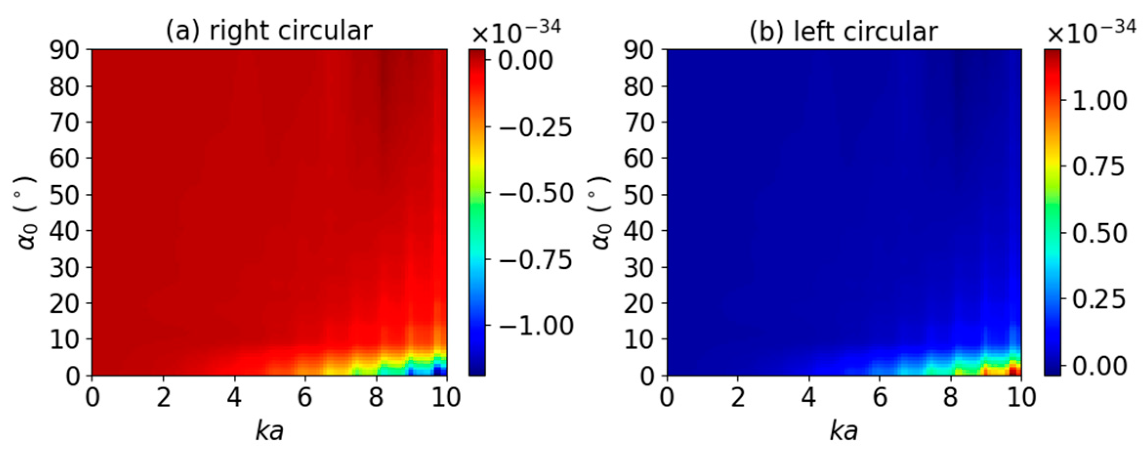
We first investigated the axial OT components by placing the charged sphere centered on a zeroth-order (l = 0) AGVBB (on-axis, x0 = y0 = 0), as shown in Figure 1. In our calculations, the surface conductivity is assumed as σs = 5.5 × 10⁻¹⁰ + 4.97 × 10⁻⁸−1m−1 (corresponding surface charge density is ρs = 10−3 C/m2). Note that, in this case, the transverse OT components vanish due to the symmetry. Figure 2 describes the calculated axial OTs ( T z u ). The dimensionless size parameter ka varies in the range 0 < ka < 10 with k = 2π/λ. The half-cone angle α0 changes within the range of 0 α0 90°. Since the zeroth-order AGVBB with linear, radial, or azimuthal polarization carries neither spin nor the orbital angular momentum, the sphere does not experience axial OT when placed in the beam. In Figure 2, the OTs for these polarizations are not given, and only the OTs for circular polarizations are shown. It can be noted that the axial OTs remain negative (for right circular polarization) and positive (for left circular polarization). This means that the zeroth-order AGVBB for circular polarizations does not reverse the sign of the axial OT. In general, the magnitude of the axial OT is larger for larger size parameter ka and smaller half-cone angle α0.
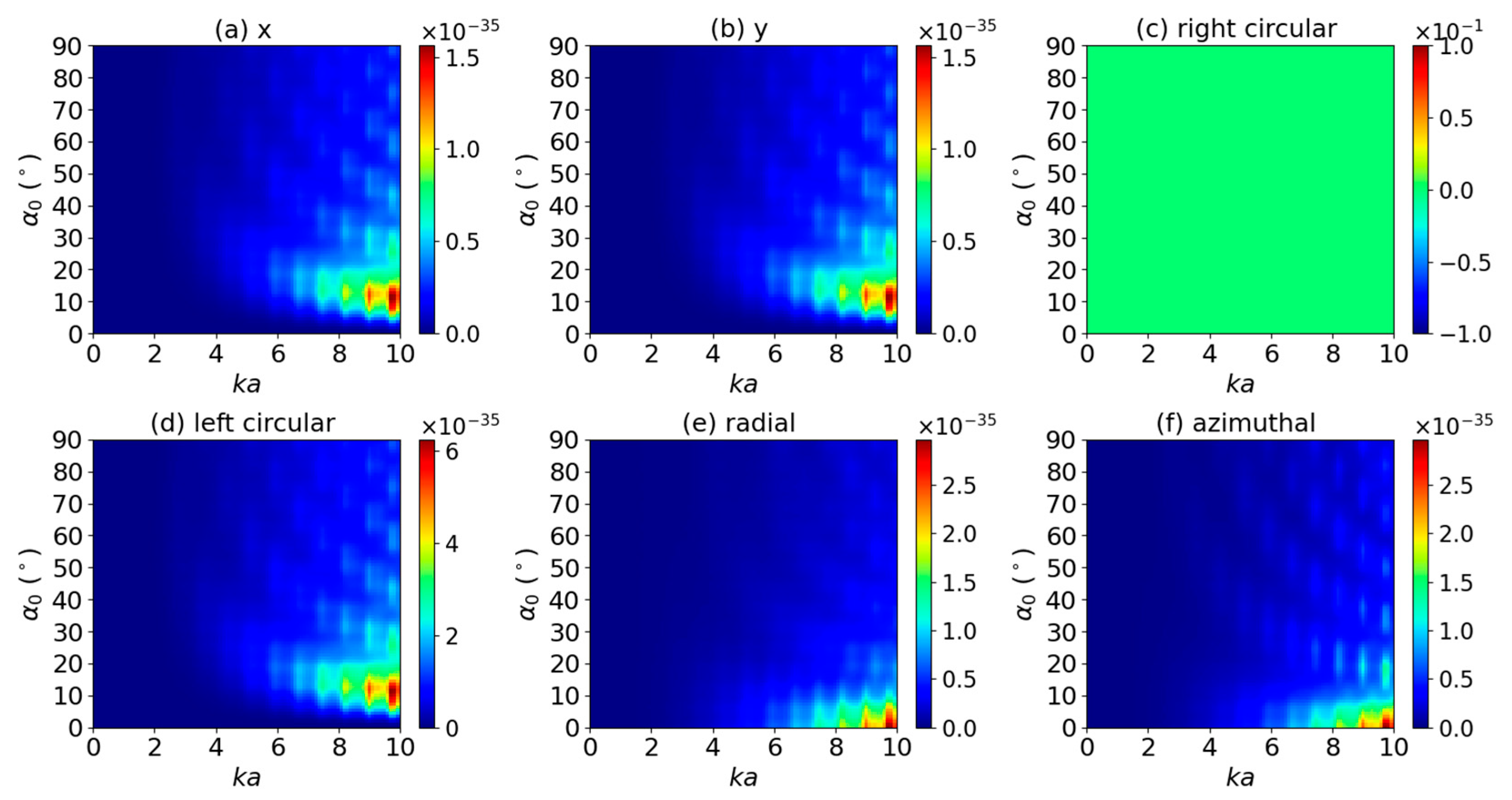
The results displayed in Figure 3 are generated to provide axial OT by the first-order (l = 1) AGVBB. It is well-known that a higher-order (l ≠ 0) AGVBB carries an axial angular momentum denoted by the phase term exp(ilφ). Each photon of the lth-order AGVBB carries OAM lℏ. In addition, if the incident beam is circular polarized, each photon carries SAM +1ℏ (left circular polarization) or −1ℏ (right circular polarization). Thus, the total angular momentum becomes (l ± 1) ℏ. When the photons are absorbed or scattered by the particle, the OAM is transferred from incident beam to the particle. Thus, for right circular polarization, the photon carries no angular momentum ((l − 1) ℏ = 0), which results in an axial OT of 0 as shown in Figure 3c. Similarly, for left circular polarization, the photon carries angular momentum 2ℏ (Figure 3d), so the magnitude of the axial OT is about twice that of the linear polarizations (Figure 3a,b). The axial OTs for linear polarizations have similar distribution. In general, the magnitude increases with the increase of size parameter ka. This is caused by the fact that a larger size particle can have more angular momentum from the incident beam, as more rays are incident on the particle. The variation of axial OT with half-cone angle α0 is dependent on the polarization. For instance, with linear and circular polarization, the maximum axial OT locates in the range between 40° < α0 < 70°, while that of radial and azimuthal polarizations locates in the range of 0° < α0 < 30°.
Next, an off-axis case (x0 = 1 μm) is studied for absorptive charged sphere placed in the lth-order AGVBB. All other parameters are the same as that of the on-axis case.
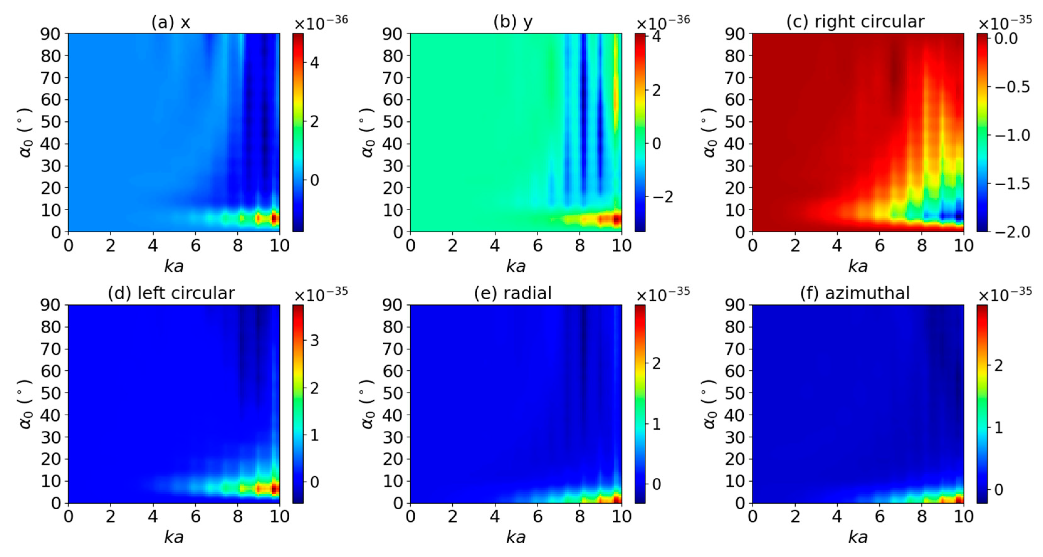
Figure 4 depicts the axial OT T z u for a charged sphere illuminated by a zeroth-order (l = 0) AGVBB. Similarly, as the AGVBBs for linear, radial, and azimuthal polarizations do not carry any angular momentum, the axial OTs vanish and are not seen in Figure 4. For right (left) circular polarizations, the axial OT remains negative (positive). This means that the sign of the axial OT is not reversed for off-axis incidence. Note that, for a neutral particle, the sign reversal can be observed as discussed in ref. [46]. Thus, depending on the position of particle in the beam, the surface charge can change the sign of the axial OT, namely the rotational direction. The comparison of Figure 2 and Figure 4 shows that the distribution of the axial OTs depends on the position of the particle in the beam.
The effect of increasing the beam order to l = 1 for off-axis incidence is displayed in Figure 5. The comparison of Figure 5 and Figure 3 shows several typical differences of the axial OT T z u for on- and off-axis incidence. The most important difference is that T z u can be either positive or negative depending on the size parameters ka and half-cone angle α0. For instance, if ka = 0.8, and the beam is linear polarized, the sign of the axial OT changes with α0. This means that one can rotate the particle clockwise or counter clockwise by changing the half-cone angle α0. This has potential application in the optical switches. Secondly, for right circular polarization, T z u is 0 for on-axis incidence, but it is non-zero for off-axis incidence.
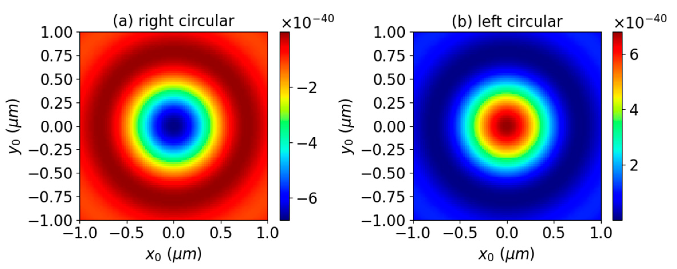
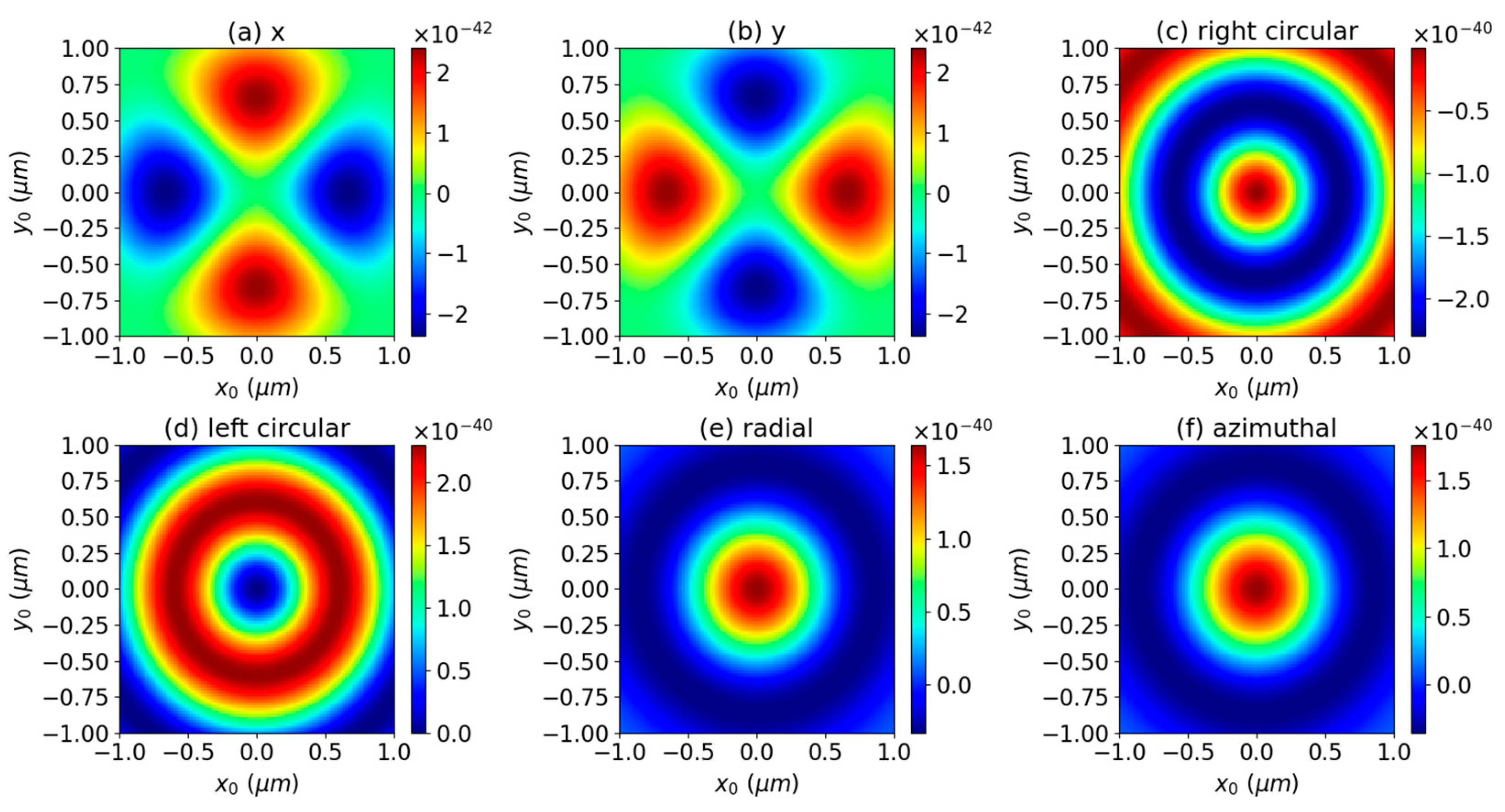
Next, the axial OT T z u is calculated by varying the relative position of the particle and the beam center in the range between −1 μm ≤ (x0, y0) ≤ 1 μm. Since the surface charge mainly affects small particles, here, we considered relatively small sphere of radius 10 nm. Figure 6 gives the results for a zeroth-order (l = 0) AGVBB with half cone-angle α0 = 15° and circular polarizations. The OTs for other polarizations vanish and are not shown. For circular polarizations, the axial OTs form a series of concentric rings. In the center, the axial OT has maximum magnitude for left circular polarization, while its magnitude is zero for right circular polarization. It is seen that the axial OT remains positive (left circular polarization) or negative (right circular polarization), which means that the sign of the axial OT is not reversed.
The effect of increasing the beam order to l = 1 is displayed in Figure 7. First, for circular, radial, and azimuthal polarizations, the axial OTs form a series of concentric rings. For right circular, radial, and azimuthal, the axial OT has central maximum magnitude but zero central magnitude for the left circular polarization. The AGVBBs for radial and azimuthal polarizations induce a larger axial OT than that for the circular polarizations. For circular, radial, and azimuthal polarizations, the axial OTs are symmetrical about the center (x0 = y0 = 0), while the symmetry is broken for linear polarizations. They form four islands: two of them are formed by maximum magnitude, while the other two are formed by minimum magnitude. For linear polarizations, two islands for minimum magnitude are arranged in the polarization direction, and the other two are perpendicular to the polarization direction. Note that the magnitude for circular polarizations is much larger than that for linear polarizations. It is very important that, for radial and azimuthal polarizations, the axial OT can be positive or negative depending on the position of particle in the beam. This means that if the particle moves radially from the beam axis, it may rotate in either the counter-clockwise or the clockwise direction.
The effects of increasing the half-cone angle to α0 = 80° for zeroth- and first-order AGVBBs on the axial OTs were also investigated, and the results are displayed in Figure 8 and Figure 9. Like the smaller half-cone angle, the axial OTs for linear, radial, and azimuthal polarizations are zero, and for circular polarizations, it forms a series of concentric rings. A comparison of Figure 6b and Figure 8b shows an important difference. For left circular polarization, the axial OT for smaller α0 remains positive, while that of larger α0 can be either positive or negative depending on the position of the particle. This means that for a larger α0, the sign reversal of axial OT can be observed. Similar results can be observed for first-order AGVBB from the comparison of Figure 7d and Figure 9d. Note that for larger α0, the concentric rings become denser.

3.2. Transverse Optical Torque

Next, we investigated the transverse OTs T x u and T y u by considering the effects of polarization, beam order, surface charge, and half-cone angle on the total transverse OT; i.e., T u = T x u + T y u . In our calculations, we assumed the radius of the particle a = 10 nm, the refractive index of the particle is m1 = 1.4746 + 1−7i, while the surrounding media is air with refractive index m2 = 1. The wavelength of the incident AGVBB is λ = 532 nm. The vortex-like character of the transverse OT is mainly discussed.
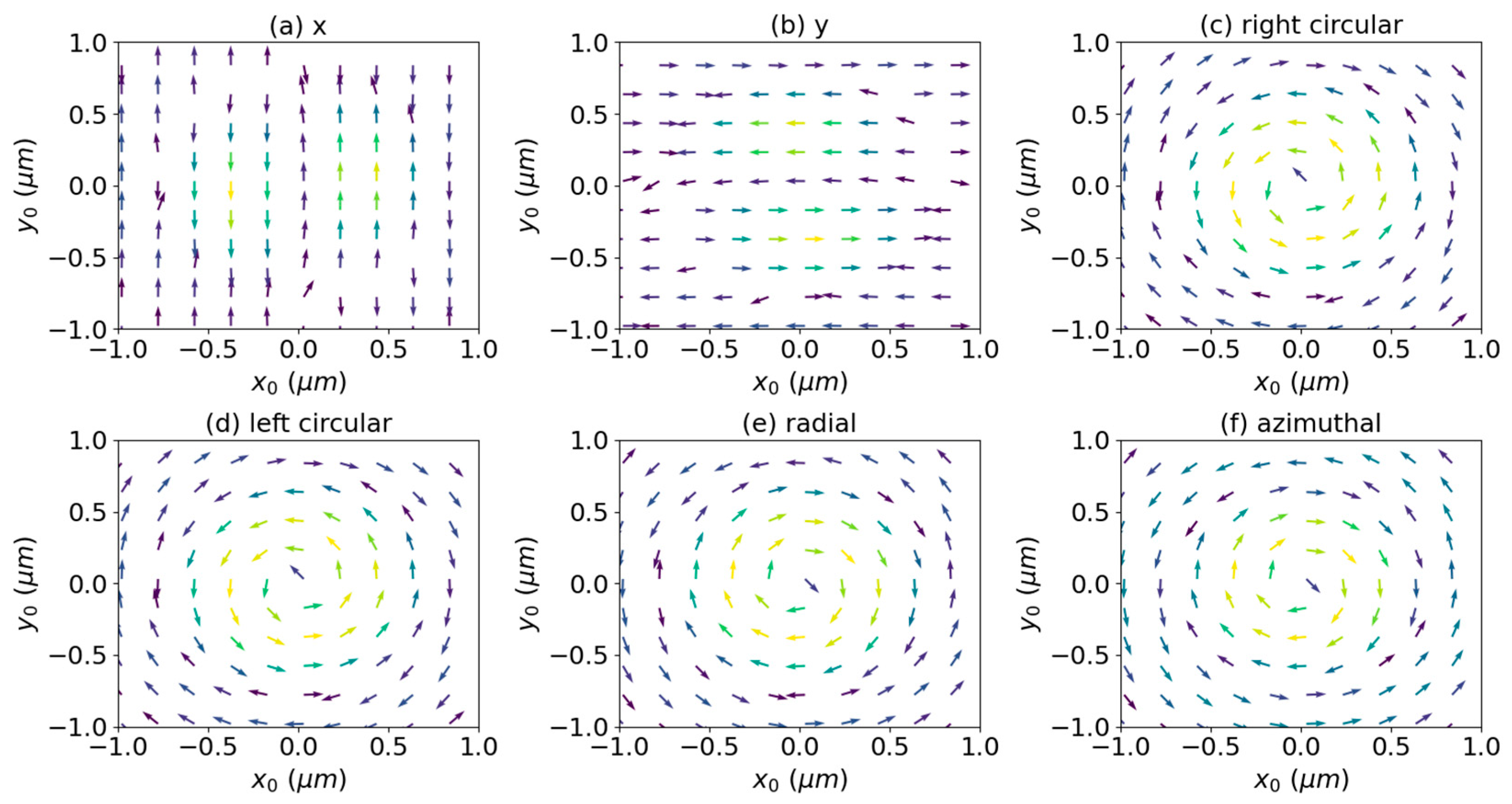
First, we considered the transverse OTs for a smaller half-cone angle. Figure 10 and Figure 11 show, respectively, the transverse OTs induced by zeroth-order (l = 0) and first-order (l = 1) AGVBBs with α0 = 15°. For the zeroth-order AGVBB with x-polarization, the transverse OT is parallel or anti-parallel to the y-axis depending on the position of particle. For x0 > 0 and r o = x 0 2 + y 0 2 < 1 , the transverse OT is parallel to the y-axis, and it is anti-parallel for r0 > 1. For x0 < 0, the transverse is opposite to that for x0 > 0. The transverse OTs for y polarization rotate by 90 degrees relative to that for the x polarization, respectively. For circular, radial, and azimuthal polarizations, the transverse OTs have vortex-like characteristics, and the vortex direction depends on the position of particle. For right circular polarization, the vortex direction is clockwise. For left circular polarization, the vortex direction is counter-clockwise for r0 < 0.7 μ m and clockwise for r0 > 0.7 μ m . The transverse OTs for radial and azimuthal polarizations have similar vortex-like character. The vortex direction is clockwise for r0 < 0.9 μ m and counter-clockwise for r0 > 0.9 μ m .
Figure 11 shows the transverse OT induced by a first-order AGVBB. Like the zeroth-order AGVBB, the transverse OT generated by a first-order AGVBB with x-polarization is parallel or anti-parallel to the y-axis. For x0 > 0, the transverse OT is anti-parallel to the y-axis for r0 < 0.6 μ m and is parallel to y-axis for r0 > 0.6 μ m . For x0 < 0, the transverse is opposite to that for x0 > 0. Similar to the case of zeroth-order AGVBB, the transverse OTs for y polarization rotate by 90° relative to that for x polarization, respectively. Furthermore, vortex-like characteristics can be observed for circular, radial, and azimuthal polarization, but they have different ranges. For right circular polarization, the vortex direction is clockwise for r0 < 0.7 μ m and anti-clockwise for r0 > 0.7 μ m . For left circular polarization, the vortex direction is always anti-clockwise. For radial and azimuthal polarizations, the vortex direction is counter-clockwise for r0 < 0.5 μ m , clockwise for 0.5 μ m < r0 < 1 μ m , and counter-clockwise for r0 > 1 μ m .
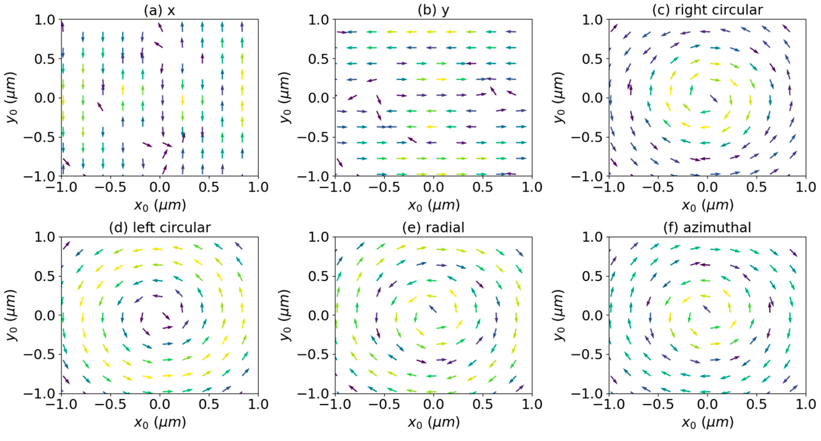
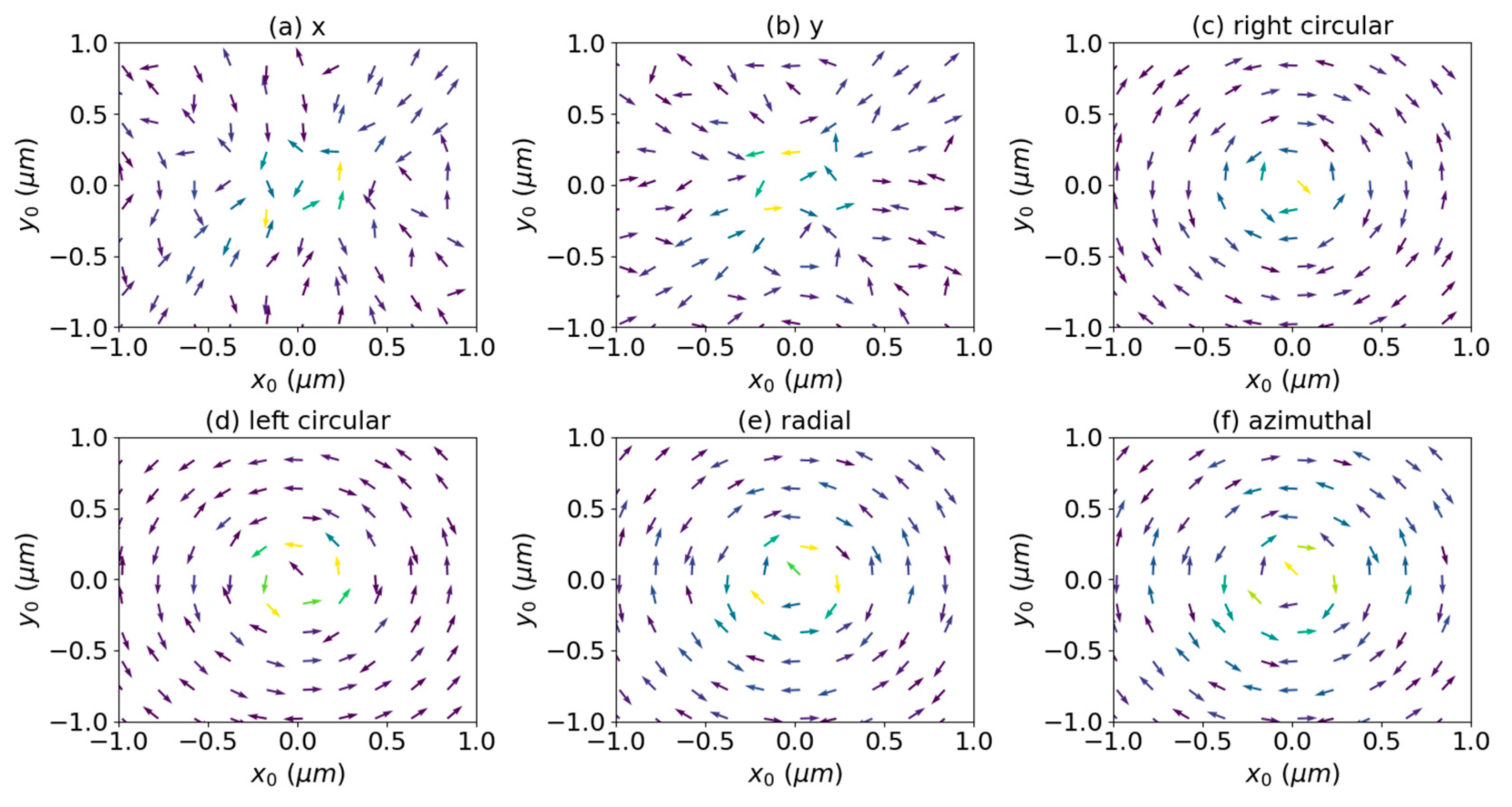
In the effect of increasing the half-cone angle to α0 = 80°, the transverse OTs is also considered, and the corresponding results for l = 0 and l = 1 are shown in Figure 12 and Figure 13, respectively. For larger α0, the transverse OT around the beam axis is much larger than that far away from beam axis, so here, we only discuss the OT in the vicinity of the beam axis. For linear polarizations, the transverse OT does not have vortex-like character, which is same with that for smaller α0. For circular, radial, and azimuthal polarizations, the vortex-like character can be seen near the beam axis for both zeroth- and first-order AGVBBs. The vortex direction for left circular polarization is counter-clockwise, while that for right circular, radial, and azimuthal polarizations is clockwise.

3.3. Effect of Surface Charge

In this section, the effect of surface charge on optical torque is mainly discussed. In the calculation, the on-axis (x0 = y0 = 0) for a charged sphere centered on a Bessel beam is considered. The refractive index of the particle is m1 = 1.4746 + 10−7i, and that for the surrounding media is m2 = 1.0. The wavelength of the incident beam is λ = 532   n m. Here, only the axial OT component T z u are considered.
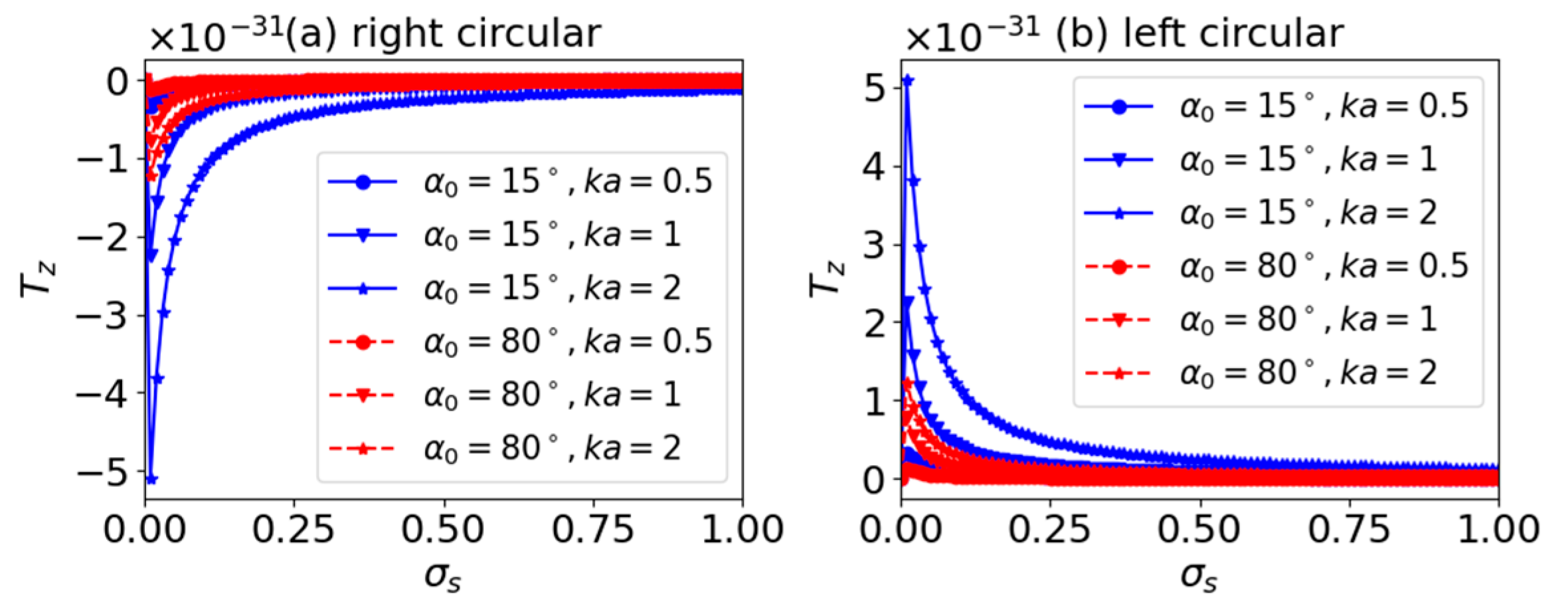
Figure 14 shows the axial OTs (Tz) versus surface conductivity σs for particles placed in a zeroth-order (l = 0) AGVBB. Various half cone-angle α0 and size parameters ka are considered, and σs varies from 0 to 1. Note that here, only the results for circular polarizations are given since the OTs for linear, radial, and azimuthal polarizations are zeros. For linear polarizations, the beam carries neither spin nor orbital angular momenta; thus, no angular momenta will be transferred from the beam to the particle, resulting in zero OTs, while for radial and azimuthal polarizations, the axial OTs are zero since the beams have null central intensities. For right circular polarization, the OTs are negative, while the OTs for left circular polarization are positive. This means that the particle does not experience negative axial OTs. With the increasing of σs, the magnitude of Tz increases first and then continuously decreases. For all α0, the magnitude of Tz increases with the size parameter ka. For right circular polarization, the beam with larger α0 produces larger OT, while for left circular polarization, larger OT is produced by the beam with smaller α0.
The effect of increasing the beam order to l = 1 on the OTs is depicted in Figure 15. Figure 15a–f correspond to linear, circular, radial, and azimuthal polarizations. For right circular polarization, the axial OT is zero. Since each photon of the beam carries both spin angular momentum −ℏ and orbit angular momentum ℏ, the total angular momentum carried by the beam is 0, causing the axial OT to vanish. In general, for other polarizations, the axial OTs are all positive. This means that the sphere spins in same handedness of the angular momentum carried by the incident beam. For all cases, the magnitude of the axial OTs increase first and then decreases until to 0. Note that the magnitude for left circular polarization is about twice that for linear polarizations. This is caused by the fact that each photon of a first-order Bessel beam with left circular polarization carries both spin angular momentum ℏ and orbit angular momentum ℏ, and the total angular momentum is 2ℏ. For linear and circular polarizations, the OTs change with α0 and ka in the same rule. In other words, the magnitude of OTs increases with the increasing of α0 and ka, while for radial and azimuthal polarizations, the magnitude decreases with α0 and increases with ka.
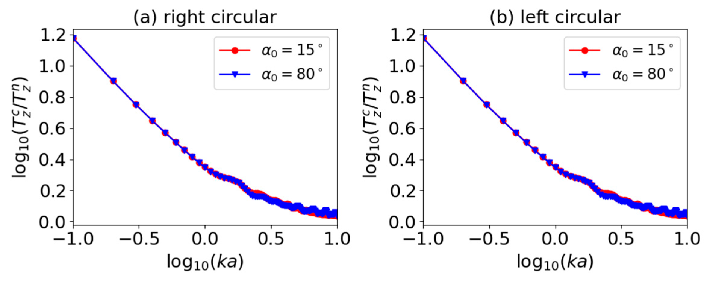
For quantitatively investigating the effects of the surface charge on axial OT, we calculated the ratio of axial OT T z u for charged and neutral particles. The ratio is defined as T z c / T z n , with T z c and T z n denoting the OTs for charged and neutral spheres, respectively.
Figure 16 shows the ratio T z c / T z n for a zeroth-order (l = 0) AGVBB. Since the axial OT for linear, radial, and azimuthal polarizations is 0, only the OTs for circular polarizations are given in Figure 16. In the calculation, we consider relatively small particles, whose size parameters ka range from 0.1 to 10. It can be noticed that for both right and left polarizations, T z c / T z n decreases with the increase of ka. This means that the surface charge mainly affects small particles since smaller particles have larger surface charge density. Once the particle is large enough, the effect can be ignored. In the meanwhile, we can find that the half-cone angle α0 does not affect the ratio T z c / T z n .
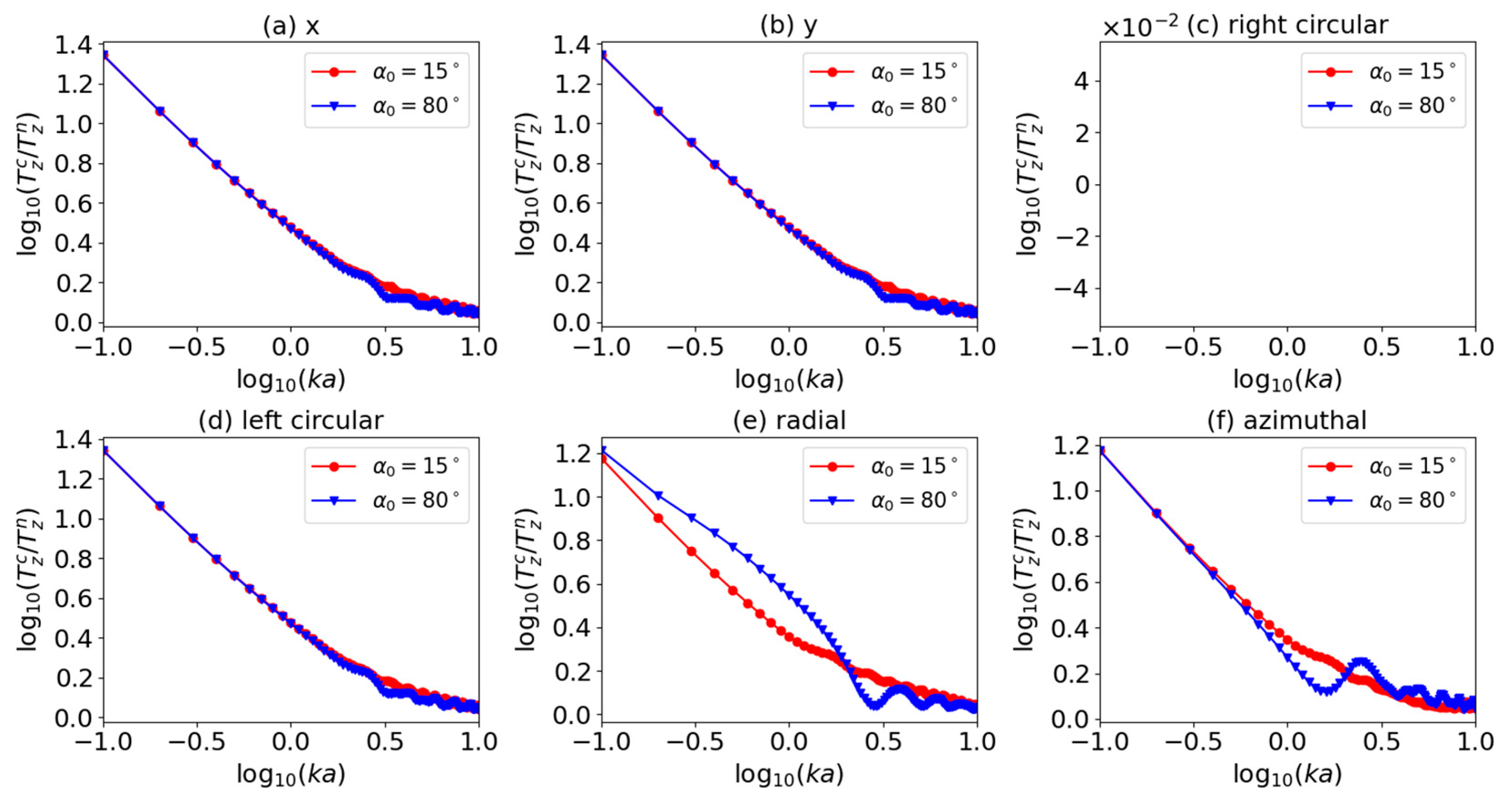
Figure 17 gives the ration T z c / T z n for first-order (l = 1) AGVBB, where the Figure 17a–f correspond to linear, circular, radial, and azimuthal polarizations. Note that since the axial OT for right circular polarization the axial OT is zero, the corresponding ratio T z c / T z n is not given in Figure 17. Similar to the case of zeroth-order (l = 0) AGVBB incidence, the ratio T z c / T z n decreases with the increase of size parameter ka. For linear and left circular polarizations, the ratios T z c / T z n versus ka are similar, and the half-cone angle α0 does not affect the ratio. However, for radial and azimuthal polarizations, the half-cone angle α0 has influence on the ratio. For instance, if the incident beam is radially polarized, the ratio for a larger angle (α0 = 80°) is larger than that for a smaller angle (α0 = 15°) when the size parameter is small. This means a larger α0 leads to greater effect of surface charge.

4. Conclusions

In summary, the OTs on a charged sphere of arbitrary size by an AGVBB were investigated using GLMT. The axial and transverse components of the OTs were separately discussed, and the sign reversal of axial OTs and the vortex-like characteristics of transverse OTs were mainly discussed. To emphasize the effect of surface charge, the axial OT versus surface conductivity σs and the ratio T z c / T z n versus ka were calculated. Numerical calculations lead to several conclusions: Like the case of neutral particle, the sign of the axial OT can be reversed, and the vortex-like character of the transverse OT can be observed. The axial OT sign reversal and vortex-like behaviors are highly sensitive to the polarization type, order, and half-cone angle. Secondly, the surface charge does not affect the sign of the axial OT but has strong effect on the magnitude of the axial OT. With the increasing of σs, the magnitude of the axial OT increases first and then continuously decreases. Thirdly, with the increase of ka, the ratio T z c / T z n decreases. This means that the surface charge mainly affects the axial OT for a relatively smaller particle. Note that for a neutral particle, the half-cone angle α0 does not affect the ratio T z c / T z n . However, if a charged sphere is illuminated by an AGVBB of radial or azimuthal polarizations, the ratio T z c / T z n is sensitive to α0. The results reported here are valuable in predicting the OT sign reversal for a absorptive charged sphere of any size in applications dealing with the design and optimization of particle-manipulation devices. Other related applications can also benefit from the results of the present investigation.

Author Contributions

Writing—Original Draft, Methodology, Software, and Editing, P.L.; Supervision, L.W.; Validation and Software, H.Y.; Writing—Reviewing, D.N.T.; Data curation, L.L.; Investigation, J.J. All authors have read and agreed to the published version of the manuscript.

Funding

This research received no external funding.

Institutional Review Board Statement

Not applicable.

Informed Consent Statement

Not applicable.

Data Availability Statement

Not applicable.

Conflicts of Interest

The authors declare no conflict of interest.

References

  1. Mishra, S.R. A vector wave analysis of a bessel beam. Opt. Commun. 1991, 85, 159–161. [Google Scholar] [CrossRef]
  2. Bouchal, Z.; Olivik, M. Non-diffractive vector bessel beams. J. Mod. Opt. 1995, 42, 1555–1566. [Google Scholar] [CrossRef]
  3. Monk, S.; Arlt, J.; Robertson, D.A.; Courtial, J.; Padgett, M.J. The generation of bessel beams at millimetre-wave frequencies by use of an axicon. Opt. Commun. 1999, 170, 213–215. [Google Scholar] [CrossRef]
  4. Arlt, J.; Dholakia, K. Generation of high-order bessel beams by use of an axicon. Opt. Commun. 2000, 177, 297–301. [Google Scholar] [CrossRef]
  5. Zhang, Y.; Wang, L.; Zheng, C. Vector propagation of radially polarized gaussian beams diffracted by an axicon. J. Opt. Soc. Am. A Opt. Image Sci. Vis. 2005, 22, 2542–2546. [Google Scholar] [CrossRef]
  6. Čižmár, T.; Šiler, M.; Zemánek, P. An optical nanotrap array movable over a milimetre range. Appl. Phys. B 2006, 84, 197–203. [Google Scholar] [CrossRef]
  7. Novitsky, A.V.; Novitsky, D.V. Negative propagation of vector bessel beams. J. Opt. Soc. Am. A Opt. Image Sci. Vis. 2007, 24, 2844–2849. [Google Scholar] [CrossRef]
  8. Yu, Y.Z.; Dou, W.B. Vector analyses of nondiffracting bessel beams. Prog. Electromagn. Res. Lett. 2008, 5, 57–71. [Google Scholar] [CrossRef] [Green Version]
  9. Brzobohatý, O.; Cizmár, T.; Zemánek, P. High quality quasi-bessel beam generated by round-tip axicon. Opt. Express 2008, 16, 12688–12700. [Google Scholar] [CrossRef] [Green Version]
  10. Wu, F.T. Geometric optics analysis on self-reconstruction of the nondiffracting beam generated from an axicon. Acta Phys. Sin. 2009, 58, 3125–3129. [Google Scholar]
  11. Chen, J.; Ng, J.; Wang, P.; Lin, Z. Analytical partial wave expansion of vector bessel beam and its application to optical binding. Opt. Lett. 2010, 35, 1674–1676. [Google Scholar] [CrossRef] [PubMed]
  12. Salem, M.A.; Bagci, H. Electromagnetic scattering of a vector bessel beam in the presence of an impedance cone. In Proceedings of the IEEE International Symposium on Antennas and Propagation & USNC/URSI National Radio Science Meeting, Orlando, FL, USA, 7–13 July 2013; pp. 1762–1763. [Google Scholar]
  13. Salem, M.A.; Bağcı, H. Behavior of obliquely incident vector bessel beams at planar interfaces. J. Opt. Soc. Am. A Opt. Image Sci. Vis. 2013, 30, 1172–1179. [Google Scholar] [CrossRef] [PubMed]
  14. Li, R.; Guo, L.; Ding, C.; Wu, Z. Scattering of an axicon-generated bessel beam by a sphere. Opt. Commun. 2013, 307, 25–31. [Google Scholar] [CrossRef]
  15. Du, T.; Wang, T.; Wu, F. Generation of three-dimensional optical bottle beams via focused non-diffracting bessel beam using an axicon. Opt. Commun. 2014, 317, 24–28. [Google Scholar] [CrossRef]
  16. Mitri, F.G.; Li, R.X.; Guo, L.X.; Ding, C.Y. Resonance scattering of a dielectric sphere illuminated by electromagnetic bessel non-diffracting (vortex) beams with arbitrary incidence and selective polarizations. Ann. Phys. 2015, 361, 120–147. [Google Scholar] [CrossRef]
  17. Yang, R.; Li, R. Optical force exerted on a rayleigh particle by a vector arbitrary-order bessel beam. J. Quant. Spectrosc. Radiat. Transf. 2016, 178, 230–243. [Google Scholar] [CrossRef]
  18. Yang, R.; Li, R.; Qin, S.; Ding, C.; Mitri, F.G. Direction reversal of the optical spin torque on a rayleigh absorptive sphere in vector bessel polarized beams. J. Opt. 2017, 19, 025602. [Google Scholar] [CrossRef]
  19. Durnin, J. Exact solutions for nondiffracting beams. i. the scalar theory. J. Opt. Soc. Am. A Opt. Image Sci. Vis. 1987, 4, 651–654. [Google Scholar] [CrossRef]
  20. Bouchal, Z.; Wagner, J.; Chlup, M. Self-reconstruction of a distorted nondiffracting beam. Opt. Commun. 1998, 151, 207–211. [Google Scholar] [CrossRef]
  21. McGloin, D.; Dholakia, K. Bessel beams: Diffraction in a new light. Contemp. Phys. 2005, 46, 15–28. [Google Scholar] [CrossRef]
  22. Volkesepulveda, K.; Garceschavez, V.; Chavezcerda, S.; Arlt, J.; Dholakia, K. Orbital angular momentum of a high-order bessel light beam. J. Opt. B Quantum Semiclass. Opt. 2002, 4, S82–S89. [Google Scholar] [CrossRef]
  23. Garcés-Chávez, V.; Arlt, J.; Dholakia, K.; Volke-Sepulveda, K.; Chávez-Cerda, S. Orbital angular momentum of a high order bessel light beam. In Proceedings of the Summaries of Papers Presented at the Lasers and Electro-Optics. CLEO ’02. Technical Diges, Long Beach, CA, USA, 24 May 2002. [Google Scholar]
  24. Mitri, F.G. Reverse propagation and negative angular momentum density flux of an optical nondiffracting nonparaxial fractional bessel vortex beam of progressive waves. J. Opt. Soc. Am. A Opt. Image Sci. Vis. 2016, 33, 1661–1667. [Google Scholar] [CrossRef] [PubMed]
  25. Mitri, F.G. Negative optical spin torque wrench of a non-diffracting non-paraxial fractional bessel vortex beam. J. Quant. Spectrosc. Radiat. Transf. 2016, 182, 172–179. [Google Scholar] [CrossRef] [Green Version]
  26. Li, R.; Yang, R.; Ding, C.; Mitri, F.G. Optical torque on a magneto-dielectric rayleigh absorptive sphere by a vector bessel (vortex) beam. J. Quant. Spectrosc. Radiat. Transf. 2017, 191, 96–115. [Google Scholar] [CrossRef]
  27. Stratton, J.A. Electromagnetic Theory; McGraw-Hill Book, Co.: New York, NY, USA, 1941. [Google Scholar]
  28. Jackson, J.D. Classical Electrodynamics, 3rd ed.; Wiley: New York, NY, USA, 1999. [Google Scholar]
  29. Gouesbet, G.; Maheu, B.; Gréhan, G. Light scattering from a sphere arbitrarily located in a gaussian beam, using a bromwich formulation. J. Opt. Soc. Am. A Opt. Image Sci. Vis. 1988, 5, 1427–1443. [Google Scholar] [CrossRef]
  30. Chang, S.; Sang, S.L. Optical torque exerted on a homogeneous sphere levitated in the circularly polarized fundamental-mode laser beam. J. Opt. Soc. Am. B Opt. Phys. 1985, 2, 1853–1860. [Google Scholar] [CrossRef]
  31. Barton, J.P.; Alexander, D.R.; Schaub, S.A. Theoretical determination of net radiation force and torque for a spherical particle illuminated by a focused laser beam. J. Appl. Phys. 1989, 66, 4594–4602. [Google Scholar] [CrossRef]
  32. Chang, S.; Sang, S.L. Optical torque exerted on a sphere in the evanescent field of a circularly-polarized gaussian laser beam. Opt. Commun. 1998, 151, 286–296. [Google Scholar] [CrossRef]
  33. Polaert, H.; Gréhan, G.; Gouesbet, G. Forces and torques exerted on a multilayered spherical particle by a focused gaussian beam. Opt. Commun. 1998, 155, 169–179. [Google Scholar] [CrossRef]
  34. Bohren, C.F.; Hunt, A.J. Scattering of electromagnetic waves by a charged sphere. Can. J. Phys. 2011, 55, 1930–1935. [Google Scholar] [CrossRef]
  35. Klacka, J.; Kocifaj, M. Scattering of electromagnetic waves by charged spheres and some physical consequences. J. Quant. Spectrosc. Radiat. Transf. 2007, 106, 170–183. [Google Scholar] [CrossRef]
  36. Klacka, J.; Kocifaj, M. On the scattering of electromagnetic waves by a charged sphere. Prog. Electromagne Res. 2010, 109, 17–35. [Google Scholar] [CrossRef] [Green Version]
  37. Kocifaj, M.; Klacka, J. Scattering of electromagnetic waves by charged spheres: Near-field external intensity distribution. Opt. Lett. 2012, 37, 265–267. [Google Scholar] [CrossRef]
  38. Hu, Q.; Xie, L. Scattering phase function of a charged spherical particle. Appl. Opt. 2015, 54, 8439–8443. [Google Scholar] [CrossRef]
  39. Xie, L.; Dou, X.Q.; Zhou, J. Sizing charged particles by phase Doppler anemometry. Appl. Opt. 2016, 55, 3279. [Google Scholar] [CrossRef] [PubMed]
  40. Bian, T.; Gao, X.; Yu, S.; Jiang, L.; Lu, J.; Leung, P.T. Scattering of light from graphene-coated nanoparticles of negative refractive index. Opt. Int. J. Light. Electron Opt. 2017, 136, 215–221. [Google Scholar] [CrossRef]
  41. Zhou, J.; Dou, X.; Xie, L. Scattering and attenuation of electromagnetic waves by partly charged particles. J. Quant. Spectrosc. Radiat. Transf. 2017, 206, 55–62. [Google Scholar] [CrossRef]
  42. Zhou, Z.; Zhang, S.; Qi, J.; Yang, X. Extension of complex refractive index model and analysis of scattering properties of charged submicron spheres. J. Quant. Spectrosc. Radiat. Transf. 2020, 242, 106735. [Google Scholar] [CrossRef]
  43. Goodman, J.W. Introduction to Fourier Optics; McGraw-Hill: New York, NY, USA, 1968. [Google Scholar]
  44. Mitri, F.G.; Li, R.X.; Guo, L.X.; Ding, C.Y. Optical tractor bessel polarized beams. J. Quant. Spectrosc. Radiat. Transf. 2016, 187, 97–115. [Google Scholar] [CrossRef]
  45. Preston, T.C.; Mason, B.J.; Reid, J.P.; Luckhaus, D.; Signorell, R. Size-dependent position of a single aerosol droplet in a Bessel beam trap. J. Opt. 2014, 16, 025702. [Google Scholar] [CrossRef]
  46. Li, R.; Ding, C.; Mitri, F.G. Optical spin torque induced by vector bessel (vortex) beams with selective polarizations on a light-absorptive sphere of arbitrary size. J. Quant. Spectrosc. Radiat. Transf. 2017, 196, 53–68. [Google Scholar] [CrossRef]
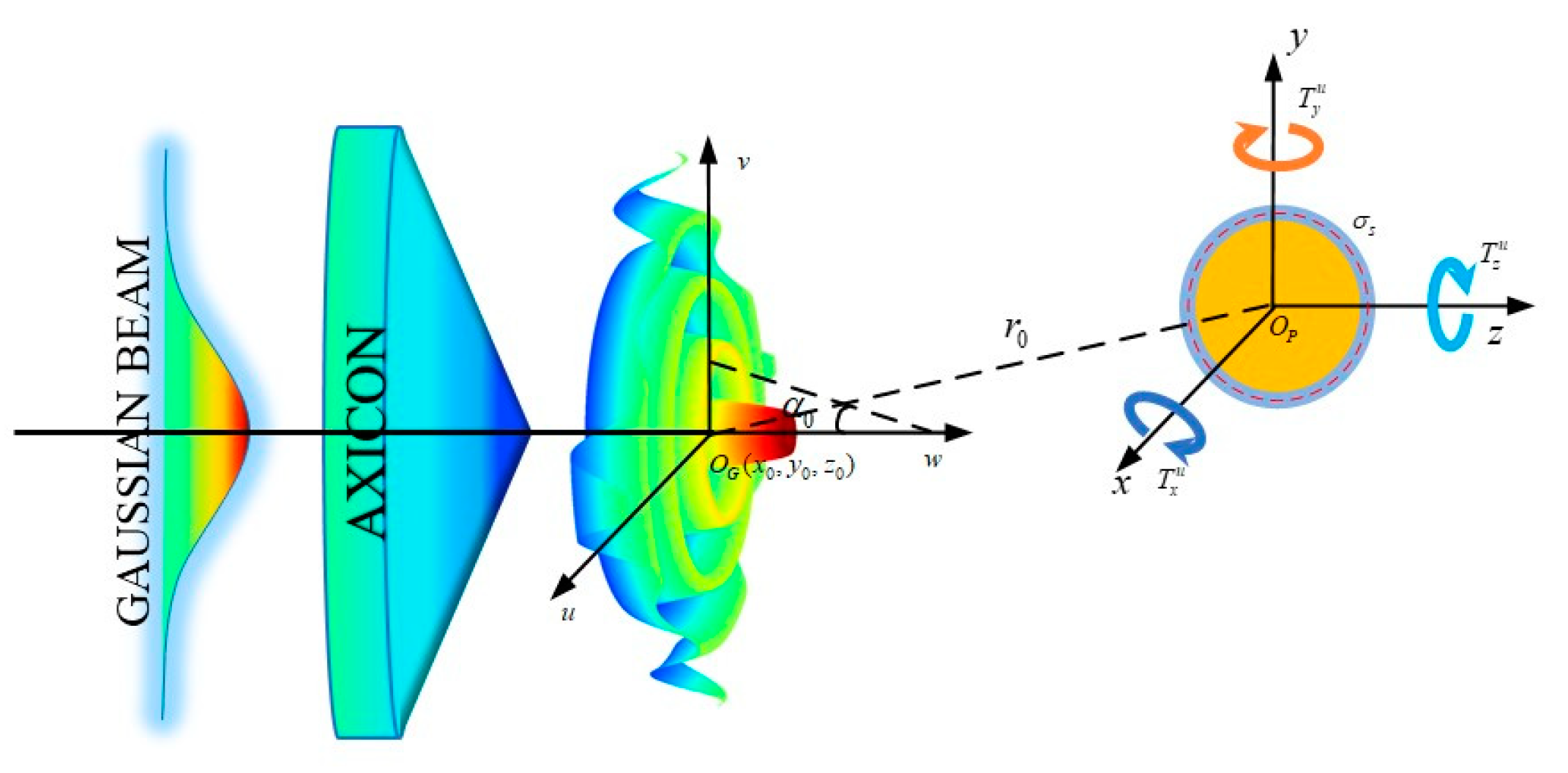
Figure 1. The schematic describing the optical torque exerted on a charged sphere.
Symmetry 15 00128 g001
Figure 2. The plots for the axial OT T z u of a zeroth-order Bessel beam centered on a charged sphere. The title of each panel denotes the polarization state.
Symmetry 15 00128 g002
Figure 3. The same as in Figure 2 but with l = 1.
Symmetry 15 00128 g003
Figure 4. The same as in Figure 2 but with x0 = 1 μm.
Symmetry 15 00128 g004
Figure 5. The same as in Figure 4 but with l = 1.
Symmetry 15 00128 g005
Figure 6. The plots for axial optical torque T z u on a charged sphere in a plane perpendicular to the propagating direction of a zeroth-order Bessel beam.
Symmetry 15 00128 g006
Figure 7. The same as Figure 6 but with l = 1.
Symmetry 15 00128 g007
Figure 8. The same as in Figure 6 but with α0 = 80°.
Symmetry 15 00128 g008
Figure 9. The same as Figure 7 but with α0 = 80°.
Symmetry 15 00128 g009
Figure 10. Transverse optical torque T z produced by a zeroth-order Bessel beam on a charged sphere at r = 10 nm with α0 = 15°.
Symmetry 15 00128 g010
Figure 11. The same as in Figure 10 but with l = 1.
Symmetry 15 00128 g011
Figure 12. The same as in Figure 10 but with α0 = 80°.
Symmetry 15 00128 g012
Figure 13. The same as in Figure 12 but with l = 1.
Symmetry 15 00128 g013
Figure 14. The plots for axial optical torque T z u of a charged sphere by a zeroth-order Bessel beam versus σs.
Symmetry 15 00128 g014
Figure 15. The same as in Figure 14 but with l = 1.
Symmetry 15 00128 g015
Figure 16. Ratio of axial optical torque for charged and neutral spheres illuminated by a zero-order Bessel beam.
Symmetry 15 00128 g016
Figure 17. The same as in Figure 16 but with l = 1.
Symmetry 15 00128 g017
Disclaimer/Publisher’s Note: The statements, opinions and data contained in all publications are solely those of the individual author(s) and contributor(s) and not of MDPI and/or the editor(s). MDPI and/or the editor(s) disclaim responsibility for any injury to people or property resulting from any ideas, methods, instructions or products referred to in the content.