1. Introduction
Mankind has always been interested in space exploration. Providing a highly reliable power system plays a critical role in the success of space missions. The space missions of this era are evolving to a whole new level, which includes the colonization of new planets and the construction of bases with a permanent presence of humans. The first mission on the list of modern space missions is the colonization of the Moon. Russia, USA, China, Japan and other countries are planning to build a base on the Moon within the next 15–20 years [
1,
2,
3].
The discovery of water at the Moon’s poles about 10 years ago and the possibility of extracting rare earth gases such as helium 3 (a non-radioactive isotope) revived interest in the Moon. In addition, it is believed that the colonization of the Moon will provide people a useful experience in preparation for the exploration of Mars. Lunar bases will have high power requirements to support activities such as scientific experiments, mining and processing, astronomical observations and surface exploration. Therefore, providing a reliable source of energy at these bases is considered extremely important.
A key component of space nuclear power systems is the prime mover, which converts thermal energy into electrical energy. Among the well-known nuclear converters with a high potential for application in space missions is the free-piston Stirling engine (FPSE). In July 2018, NASA acknowledged the FPSE as the most reliable heat engine in the history of civilization. The FPSE unit began operation in the Glenn research center in 2002 and has been operating continuously for more than 14 years without any signs of degradation [
4].
Due to the extremely low temperatures and harsh environmental conditions in space, the heat rejection process is considered to be quite complex and implies high demands on the design. Therefore, designing a highly efficient heat rejection system is crucial for the nominal performance and maximum efficiency of the power generation system. Heat rejection systems for space nuclear power systems should be coordinated with the thermodynamic cycles of the power plants in such a way as to maximize the performance of the space nuclear power system while maintaining the specific mass of the heat rejection system and the total specific gravity of the power generation system (kg/kW) to a minimum [
5].
Several heat rejection systems have been implemented in space, one of which is widely used—the fluid loop system. This system transfers heat from the equipment, in our case the power generation system, to the radiators, which then rejects the heat into free space. This system can be a mechanically pumped single-phase circuit or a two-phase heat pipe circuit.
Heat pipes have the significant advantage of being completely passive with no moving parts, making them exceptionally suitable for use in space. A heat pipe is a thin hollow pipe filled with a liquid appropriate for the temperature range in which it is intended to operate. At the hot end, the liquid is in the vapor phase and tries to fill the pipe by passing through the pipe to the cold end, where it gradually condenses into the liquid phase. The walls of the pipe, or corresponding channels cut into the pipe, are filled with wick material which returns the liquid by surface tension to the hot end where it is re-evaporated and recirculated. Heat pipes are most commonly used because of their lightness and high thermal conductivity.
Currently, heat pipes are often used for the thermal control of spacecrafts. The heat pipe evaporator is mounted on the components that need to be cooled, and the condenser is mounted on the heatsink panel to dissipate heat. However, heat pipes have a number of limitations compared to a mechanically pumped loop heat rejection system. These limitations are mainly related to the amount of heat rejected and the flexibility of heat transfer control.
On the other hand, the mechanically pumped loop heat rejection system ensures efficient transfer of large amounts of heat at a controlled heat transfer rate and operating temperature. Several works discuss mechanically pumped single-phase liquid loop heat rejection systems and their potential for future space missions. In one study [
6], the experimental and analytical results of a heat rejection system consisting of a single-phase mechanically pumped loop and a space radiator are presented. The prototype was developed for future crewed exploration missions to provide a large amount of heat dissipation capability. In [
7], a study on refrigerant selection for a high-temperature mechanically pumped fluid loop for space applications is presented; it describes the trade study used to select the high-temperature working fluid for the system and the initial development testing of loop components. In [
8], a mini mechanically pumped loop designed for the thermal control of small satellites is presented. In [
9,
10], a highly self-adaptive cold plate for the single-phase mechanically pumped fluid loop for spacecraft thermal management and hybrid system are studied.
In addition to mechanically pumped single-phase liquid loop systems, heat pipes are also actively being studied. In [
11], a heat rejection technology based on heat pipes for space application is presented, where the feasibility of the proposed model is described. In [
12], a titanium–water heat pipe radiator for the thermal management of space fission power systems, such as the Kilopower system, is studied. The testing results demonstrated that the developed radiator is able to transfer the required power at the working temperature of 400 K under space-like testing conditions. In [
13], a space power system consisting of FPSEs based on potassium heat pipes is presented. In [
14,
15], sodium variable conductance heat pipes with a Carbon–Carbon radiator for radioisotope Stirling systems are studied.
The active research and development of heat rejection systems for space applications confirms the importance of the studies conducted in this paper. In mathematical modeling, the symmetry of the distribution of heat fluxes as a result of heat conduction along the radiator fins from the radiator pipes and radiation heat flows from two symmetrical surfaces of the radiator was taken into account. In this work, we consider a mechanically pumped single-phase heat rejection system, which is a continuation of our previous work [
16]. The calculation method in our previous work took into account the influence of uneven temperature distribution over the surface of the radiator, variable speed and temperature of the refrigerant in the radiator pipes. This is considered crucial while designing a radiator for space applications. However, the main design parameters of the radiator based on the choice of the refrigerant were determined using a time-consuming iterative process, which is discussed in detail in the work itself.
The authors have continued research in this area and developed an enhanced calculation method of a heat rejection system operating on the moon, which allows the time to be decreased for determining the main design parameters of the radiator and the most effective refrigerant. The enhanced method made it possible to effectively evaluate the capabilities of various refrigerants and choose the radiator parameters and the refrigerant flow regime. This was possible by deriving formulas based on acceptable assumptions, which are explained in detail in the next section. In addition, a comparative analysis is presented for two refrigerants: helium and liquid ammonia. It is important to note that the calculation method is not limited to a specific type of refrigerant. Any refrigerant can be considered in the calculation method; however, the operating range of the refrigerant should meet the requirements of the heat rejection system. The refrigerant operating temperature and pressure ranges before encountering a phase change, thermal capacity, thermal conductivity and viscosity should be taken into consideration when choosing a refrigerant.
Helium and liquid ammonia were considered in this work due to their attractive thermophysical properties and suitable operational conditions for the considered FPSE heat rejection system. In a previously published work of the authors, a detailed comparative study of several refrigerants was presented [
17]. Helium gas is known for its high heat-transfer capabilities, one of the main reasons it is used as the working fluid inside the FPSE. On the other hand, the choice of liquid ammonia as a refrigerant is due to its proven advantages in space thermal management systems. Advantages of ammonia include: high thermal capacity, wide range of operating temperatures, low weight when compared to water and its viscosity which leads to minimum pumping power through pipes. The International Space Station’s (ISS) active thermal control systems include a liquid-ammonia coolant loop along the station’s main truss which keeps the station’s electricity-generating solar panels cool [
18].
This work is organized as follows: First, an overview of the lunar power plant proposed is described. Second, the main steps of the enhanced calculation method are presented. The dependences of the change in the geometrical parameters of the radiator on the thermodynamic properties of the refrigerant and the flow regime are established. Then, the calculation results are presented. An example of selecting the dimensions of a radiator with a given specific radiation flux per unit area using helium and liquid ammonia is presented. Finally, the conclusions are provided.
2. Materials and Methods
A detailed description of the heat rejection system of the FPSE operating on the Moon has already been presented in one of the published works of the authors [
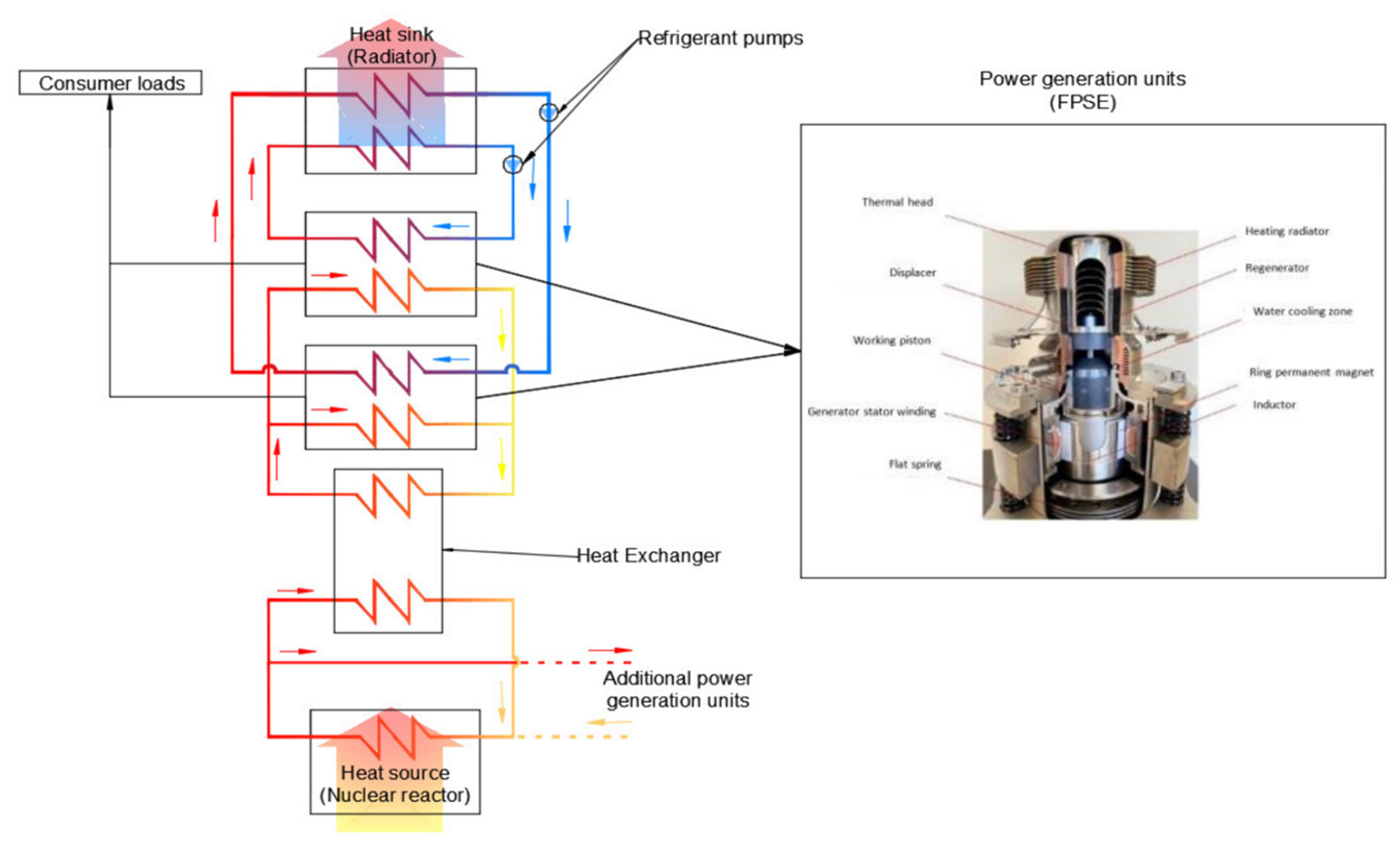
19]. However, it is also presented in this work to give the reader a better understanding of the calculation method and the results presented in this work. An overview diagram of the FPSE and the heat rejection system is shown in
Figure 1. The engine model considered in this work was developed by Microgen Engine Corporation and is the same model implemented by Nauka-Power Technology LLC in its autonomous off-grid power solutions for hard to reach and remote facilities which require a reliable source of power [
20,
21]. This particular FPSE model has a high potential for application in future space missions.
The proposed power plant considers supplying heat from the nuclear reactor to the FPSE. The FPSE has two main moving parts: the displacer and the working piston. Both operate in a closed helium environment and are not mechanically coupled to each other. Helium shuttles from the expansion zone (heater) to the compression zone (cooler) due to the temperature difference and cyclical movements of the displacer and power piston. Between the expansion and compression zones there is a porous heat regenerator, which increases the efficiency of the cooling and heat processes of the helium shuttling between the zones. The mechanical energy of the reciprocating movement of the working piston is transformed into electrical energy through a single-phase synchronous linear generator, the inductor of which with permanent magnets is connected to the working piston. Several FPSEs can be powered by the nuclear reactor in the system, however, for convenience, only one FPSE was considered in this paper.
The FPSE is a combination of heat exchangers: a heater, a regenerator and a cooler, which form an internal circuit. In the cooler, heat is rejected from the helium to the outer circuit. The outer circuit (heat rejection system) consists of a pump and a radiator, in which a refrigerant circulates. The heat transferred from the internal circuit to the outer circuit is rejected into free space by the radiator.
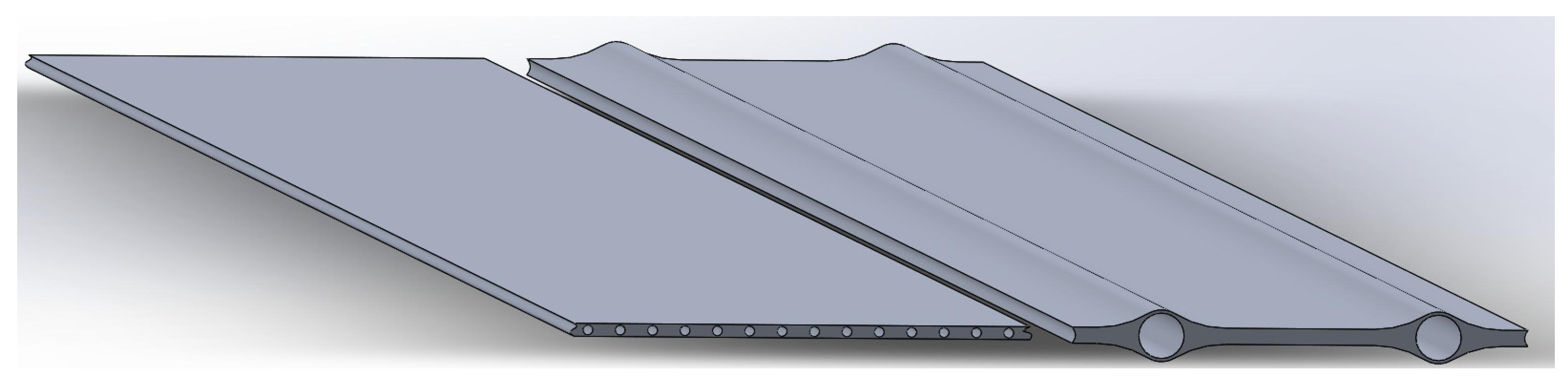
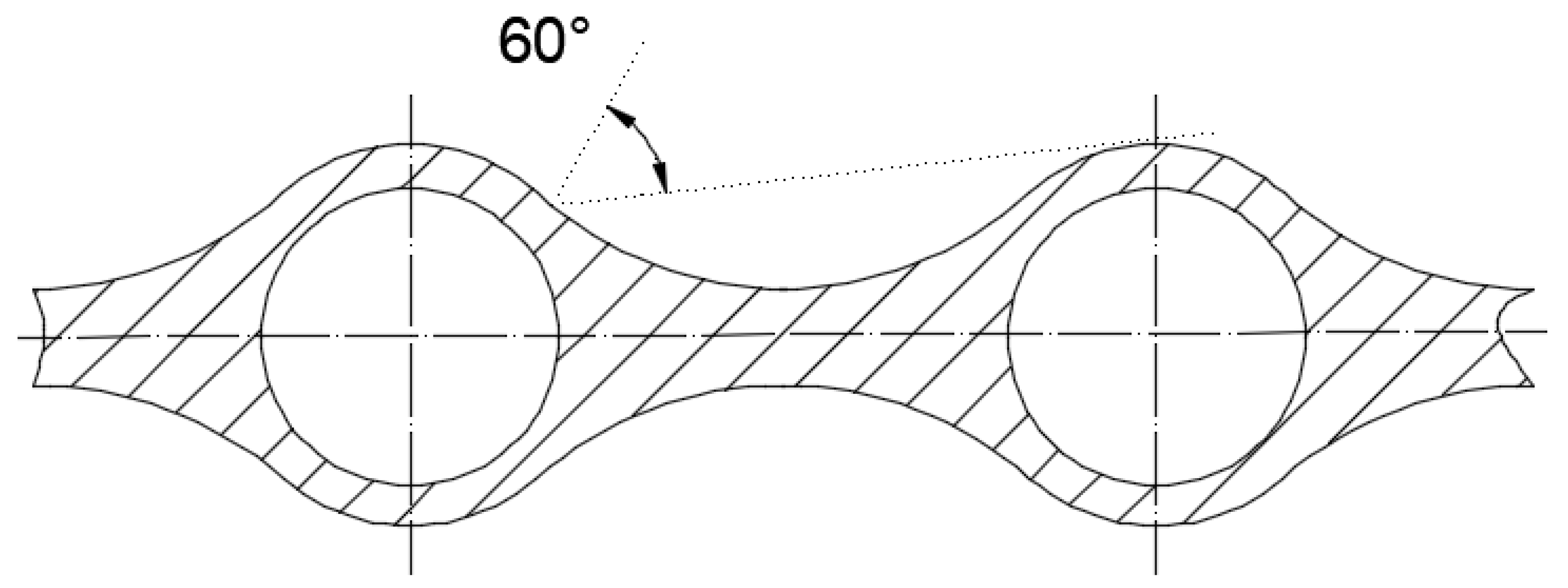
Structurally, the radiator is a set of radiant panels operating according to a parallel scheme of inclusion in the radiator’s hydraulic path, connected together by a system of inlet and outlet collectors. The structural form of the radiating panel can be made in the form of parallel pipes, to which the fins are rigidly attached [
22]. In this work, two options for the radiator were considered (
Figure 2), in which the diameter of the pipes is smaller (option 1) or greater (option 2) than the thickness of the radiator fin. Each radiator pipe has two fins for radiating heat into free space: one from the left side and another from the right side. The fins are symmetric with respect to the pipe.
Appendix A provides more detailed information about the design features of the radiator options.
The heat transfer processes occurring in the outer circuit (heat rejection system) are convective heat transfer (
) and radiation (
. Convective heat transfer occurs in the radiator pipes while the refrigerant is passing through them. Heat is transferred from the refrigerant to the pipes’ walls. Afterwards, heat is radiated from the radiator surface into free space [
23,
24]. Considering the two heat transfer processes occurring, the following condition must be satisfied:
To calculate the radiator, we must specify the total heat flux that must be rejected (); temperature at the inlet and outlet of the radiator pipe (; ); and the thermodynamic parameters of the refrigerant (; ;; ; ; ; ).
Next, the total flow of the refrigerant through the radiator is determined:
where the change in stagnation enthalpy through one pipe:
Through one radiator pipe, the refrigerant mass flow is as follows:
The refrigerant mass flow must be constant and is determined as follows:
Heat
transferred as a result of convection:
where the surface area for heat transfer:
The heat transferred to the walls of the radiator pipe is further distributed along the fins of the radiator by thermal conduction and then the heat is rejected by radiation from the surface of the radiator
:
where the radiation area:
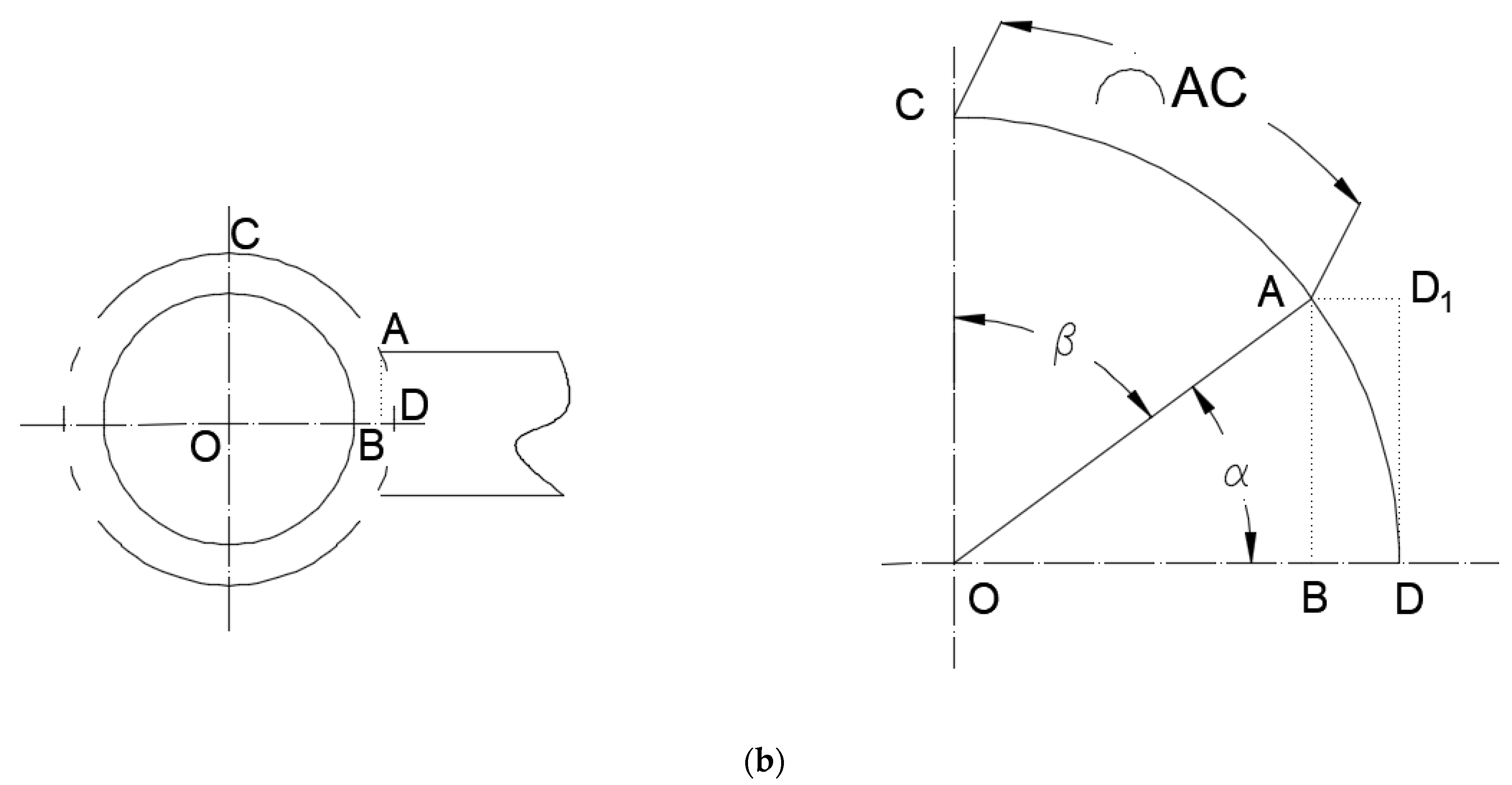
It is worth noting that the radiation is considered from two surfaces of the radiator. Detailed information about the calculation of the width of one section of the radiation surface
and the total width of the radiator
is given in
Appendix A.
Based on the condition of heat balance (), the thermal state of the radiator fin was determined. As already mentioned, the enhanced calculation method of the heat rejection system allows the time to be decreased for determining the main design parameters of the radiator and the most effective refrigerant. The enhanced calculation method is carried out in two stages:
The amount of heat radiated from the surfaces of the radiator fins at a constant ambient temperature is determined by the surface area and the temperature level in the radiator fins. Moreover, in formula (9), the temperatures are to the fourth power ; therefore, the greater the difference between the surface temperature TR and ambient temperature , the more efficient the heat rejection. At a given ambient temperature , the specific heat flux per unit area depends on the fin surface temperature TR.
For the preliminary calculations, it was assumed that the temperature of the fin is constant and equal to the temperature of the inner surface of the pipe (
), and the temperature of the refrigerant in the pipe is equal to the average temperature:
Subsequent studies have shown the validity of this assumption. A temperature difference coefficient for convective heat transfer
is introduced for convenience. The closer the wall temperature
to the refrigerant temperature
, the greater the temperature difference between the radiator fin
TR and the ambient temperature
; therefore, the greater the heat flux that will be rejected per unit area
. Theoretically, the minimum total radiator area for heat rejection of a given heat flux
will be when
:
Then, the maximum heat flux emitted from the radiator surface:
According to these formulas, it is possible to determine the limiting values of the radiator area and heat flux for evaluating the results obtained. In practice, it is impossible to achieve them, since a temperature difference is necessary for the heat rejection process, therefore and .
The total area of the radiation surface of the radiator is as follows:
A formula for determining the pipe diameter
d for a given mean Reynolds number
is derived. The Reynolds number of the refrigerant at the pipe inlet can be determined as follows:
and
Further, we perform rearrangement of the formulas:
The total flow rate
is found from the formulas (5) and (6):
Substituting (18) into (19):
We obtain a formula showing the relationship between the pipe diameter and the number of radiator pipes:
Or considering formula (3), we obtain:
We combine all the parameters of the initial data for calculation in this formula and introduce a coefficient for convenience:
For a given number of pipes, the formula for calculating the diameter of the radiator pipe is as follows:
It is possible to set the diameter of the radiator pipe and determine the number of pipes:
In this case, the number of pipes must be an integer. This can be achieved by appropriate adjustment of the diameter
d. Then, we derive the formula for calculating the width of one section of the radiation surface from (
) and (
):
A necessary condition (check
Appendix A) in this case is:
The thickness of the pipe (
t) is chosen based on the strength calculation of the structure. The total width of the radiator was calculated as follows:
Ceteris paribus, setting the coefficient or wall temperature , we can determine the width of the radiator fin , providing the temperature difference (). When specifying the number of radiator pipes, we define:
The formula for determining the length of the radiator can be obtained by substituting into formula (33): the formulas for determining the radiator’s radiation area
(32); width of the radiation surface for one fin section
(29); and number of pipes
(28):
- 3.
Specific heat flux of radiator surface:
The total radiation area of the radiator and the specific heat flux , taking into account the assumptions made for a given heat flux and ambient temperature , depends on the pipe wall temperature and coefficient of temperature difference . The dimensional formulas and are determined by the number of pipes , pipe diameter d, thermodynamic parameters of the refrigerant and flow regime Re.
Another important factor for evaluating the efficiency of a radiator design is the power spent on pumping the refrigerant through the radiator. By changing the number of radiator pipes, it is possible to achieve the required geometric dimensions with acceptable power losses for pumping the refrigerant through the radiator. The calculation of the hydraulic resistance inside the radiator was carried out using the following method.
The power spent on pumping the refrigerant through the radiator was calculated as follows:
The Darcy friction factor for laminar flow:
The pressure drop was calculated as follows:
Considering that the refrigerant velocity:
For a laminar flow, this formula can be rearranged, taking into account formula (37):
or
where the pumping power coefficient:
An increase in the pipe length and a decrease in the pipe diameter lead to an increase in the power for pumping the refrigerant. The pipe length depends on the diameter (34), and the diameter is related to the number of pipes (28).
The formulas include the Nusselt number
Nu and Reynolds
Re, which characterize the features of heat transfer and refrigerant flow [
24,
25].
For the condition 0.5 <
Pr < 1.5:
For the condition 1.5 <
Pr < 500:
- 3.
Nusselt number for turbulent flow:
where Prandtl number:
The above formulas made it possible to study the influence of the flow regime on the geometrical parameters of the radiator and the power spent on pumping the refrigerant depending on the given specific heat flux emitted by the radiator for various refrigerants.
Based on the studies carried out, the main design parameters of the radiator can be preliminarily determined (
. After conducting the preliminary calculation using the above formulas, the obtained results are refined using the previously developed calculation method of the radiator (two-dimensional model), which takes into account the uneven distribution of temperatures over the area of the radiator fin [
19].
To compare two refrigerants with the same initial data (/, the following formulas are proposed (subscripts 1 and 2 are used to indicate the refrigerant):
From formula (24), we obtain:
For flows with the same mean value of Reynolds number
:
or
where the viscosity and enthalpy ratios:
- 2.
From formula (29):
where the radiation surface ratio:
- 3.
- 4.
Total required radiation surface, an important parameter for evaluating the heat rejection efficiency of the refrigerant:
For laminar flows (
;
Nu = 3.66), the formulas are simplified:
For flows with the same mean value of Reynolds number
:
3. Results and Discussion
The initial data for calculating the radiator are:
The ambient temperature in this study is of great importance due to its direct influence on the efficiency of the heat rejection process. Temperatures on the Moon are extreme. Ranges of temperature changes relative to their location on the Moon and a parametric study of the energy systems of the lunar base can be found in [
26,
27]. The location of the lunar power plant considered in this work was at one of the poles, where the maximum ambient temperature reaches 200 K (−73 °C), which is considered the most suitable for lunar bases according to several space agencies. At lower ambient temperatures, the difference between the temperature of the fins and the ambient temperature increases, resulting in an increase in the efficiency of heat rejection.
Helium and liquid ammonia were considered as refrigerants; their main properties (gas constant, enthalpy, heat capacity
Cp, dynamic viscosity, thermal conductivity) were set according to the data from these works [
28,
29]. The main parameters of the FPSE considered in the calculation are shown in
Table 1.
To compare the efficiency of refrigerants, the following conditions were set constant:
The heat flow that must be rejected in the radiator from the FPSE 2500 W;
Refrigerant temperatures at the inlet and outlet of the radiator pipe / = 280/260 (;
Average pipe wall temperature , consequently ;
Refrigerant pressure in the heat rejection loop system—1 MPa;
Fin thickness = 0.005 m.
If the specified temperature difference is provided as , then the total radiation surface area of the radiator, regardless of the refrigerant used and the flow regime, will be constant (14): .
Initially, helium was considered as a refrigerant for the calculation. During a laminar flow (
;
Nu = 3.66) and based on the given initial data, the fin width remains constant (29)
(Option 1 in
Appendix A).
When specifying the pipe diameter, the condition must be taken into account. For the example under consideration, with a pipe diameter of 2.0 mm and a thickness t = 1.0 mm, the distance between two pipes is only 1.2 mm.
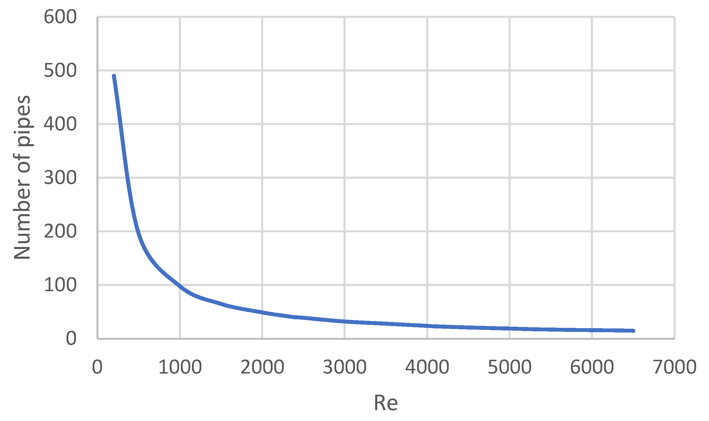
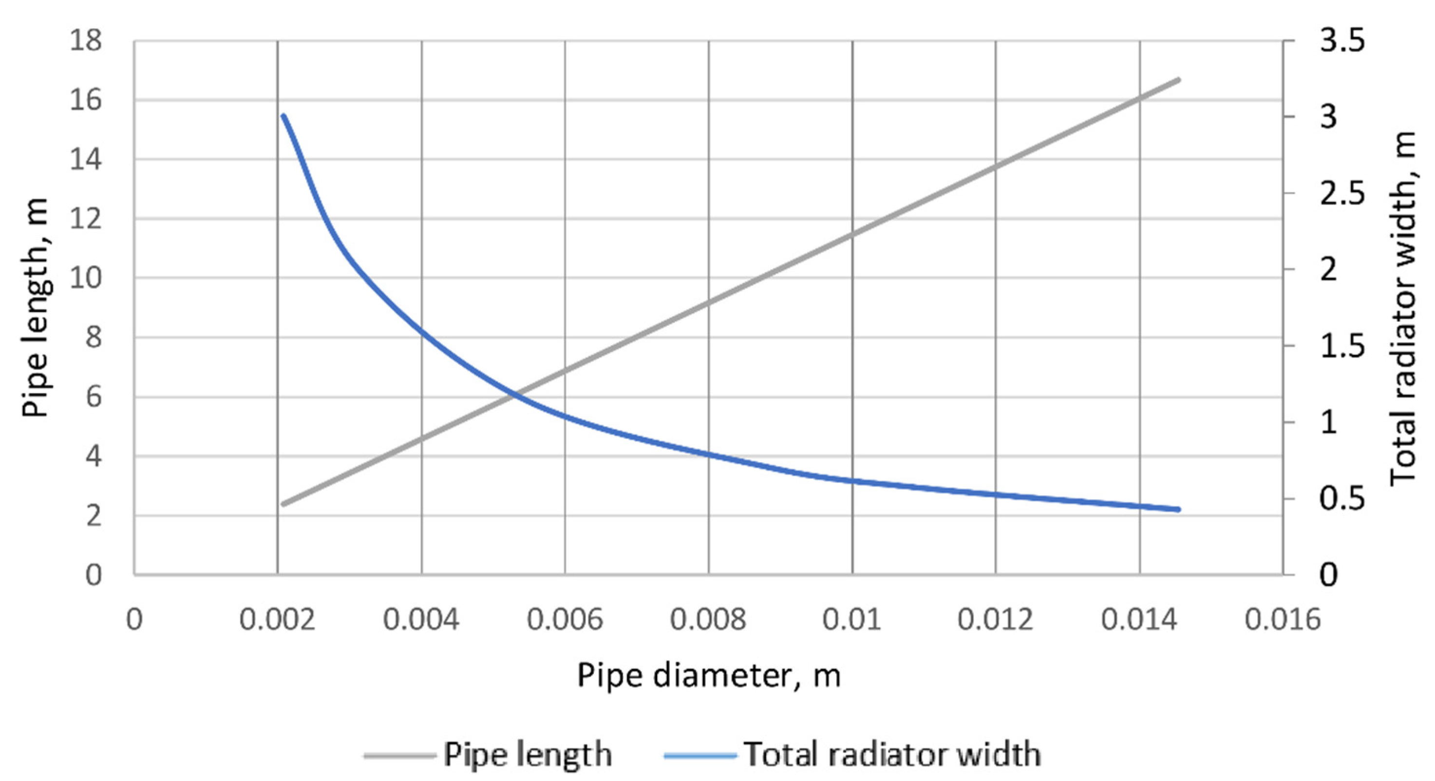
Depending on the considered pipe diameter, we determine the number of pipes
, pipe length
, as well as the total width of the radiator
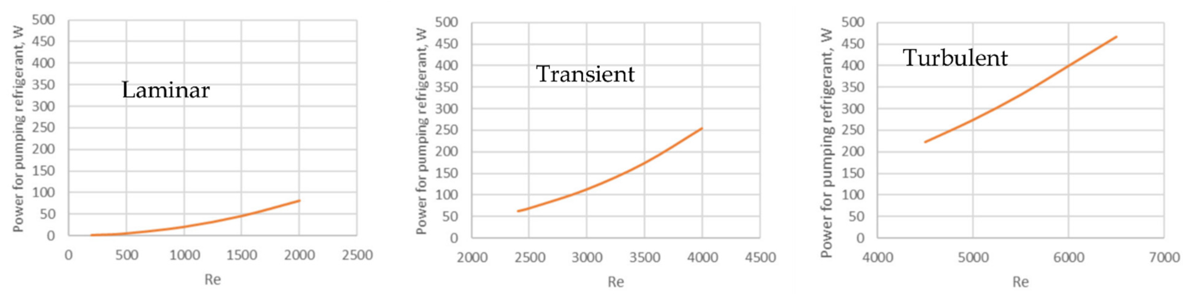
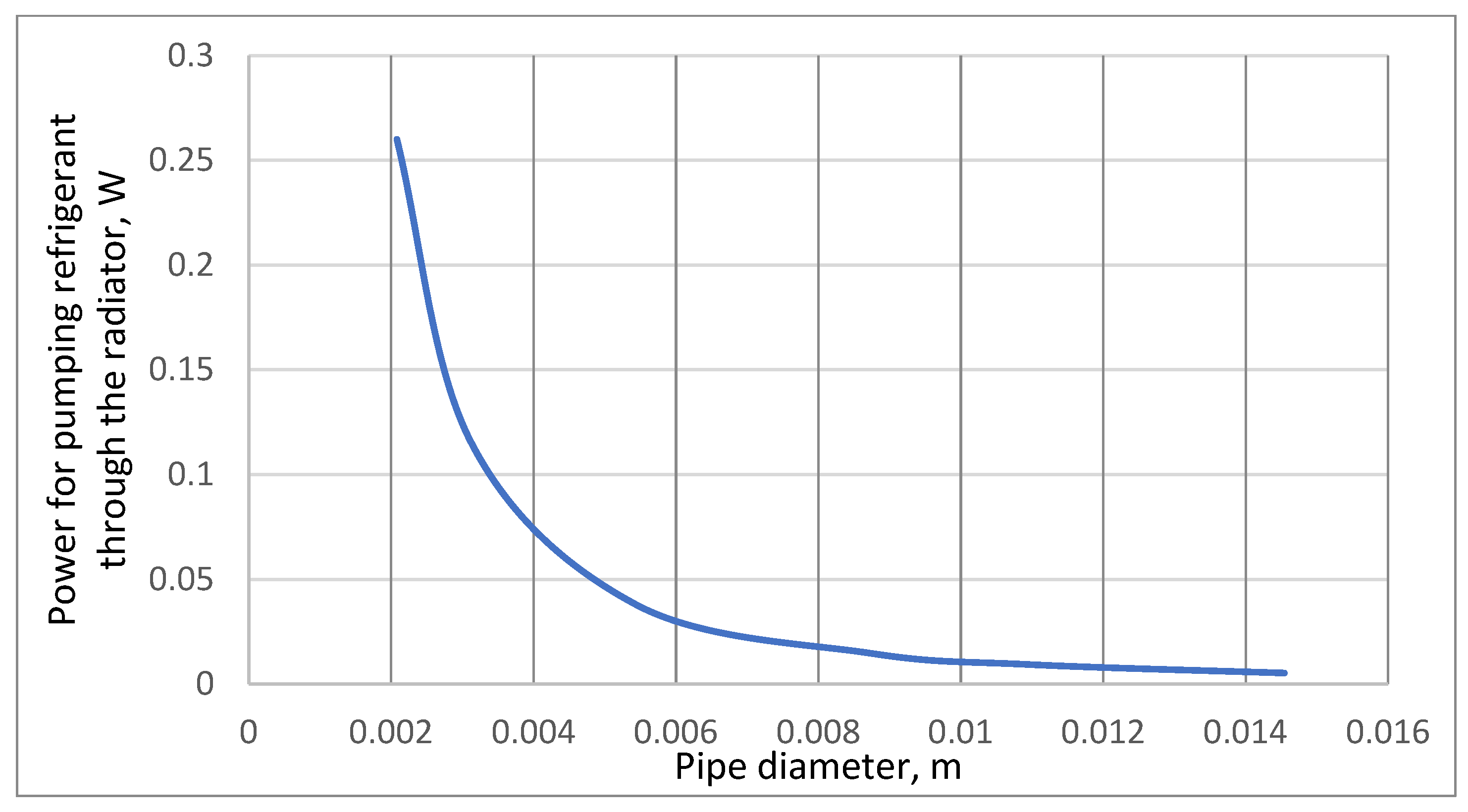
and the power spent on pumping the refrigerant
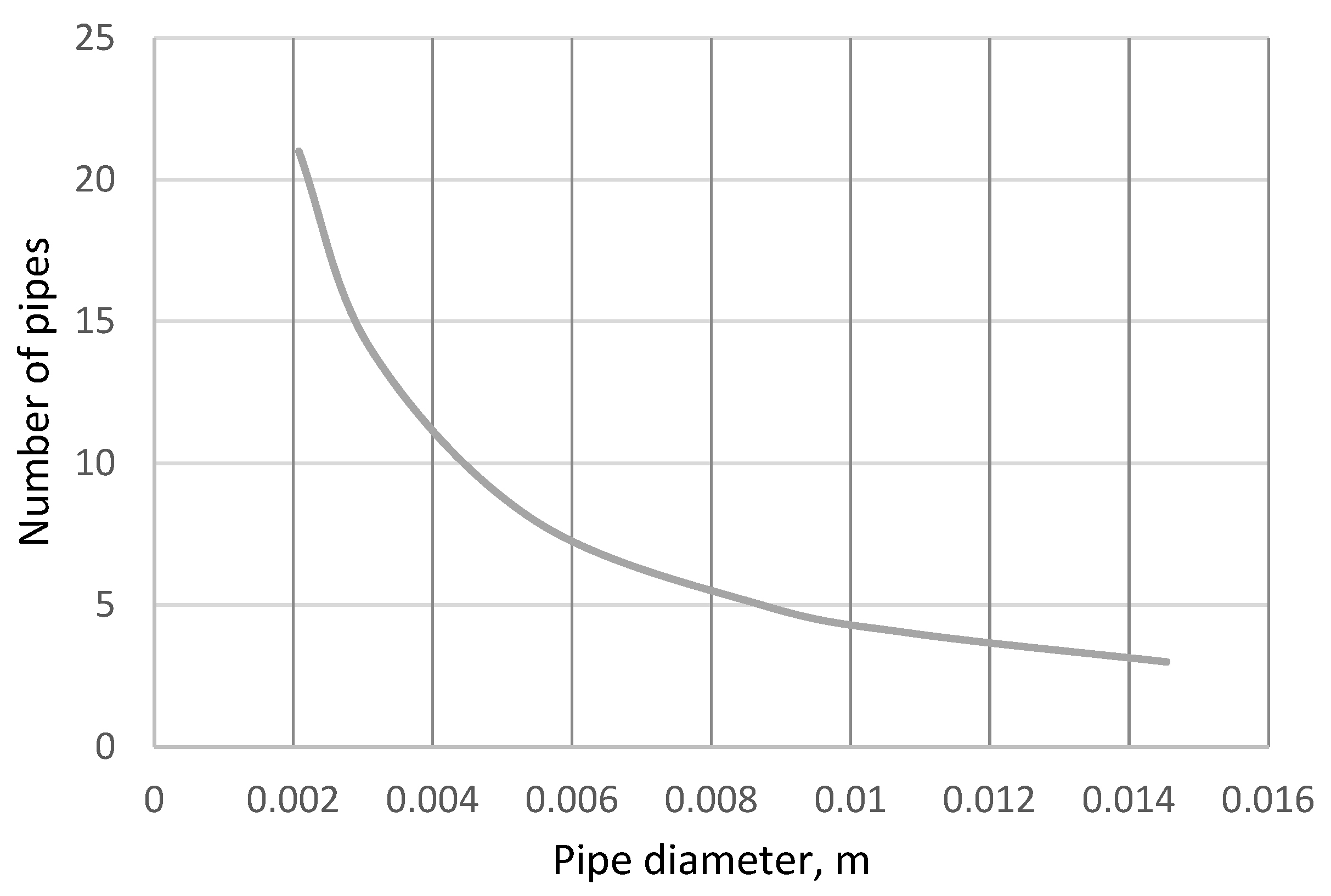
for different flow rates
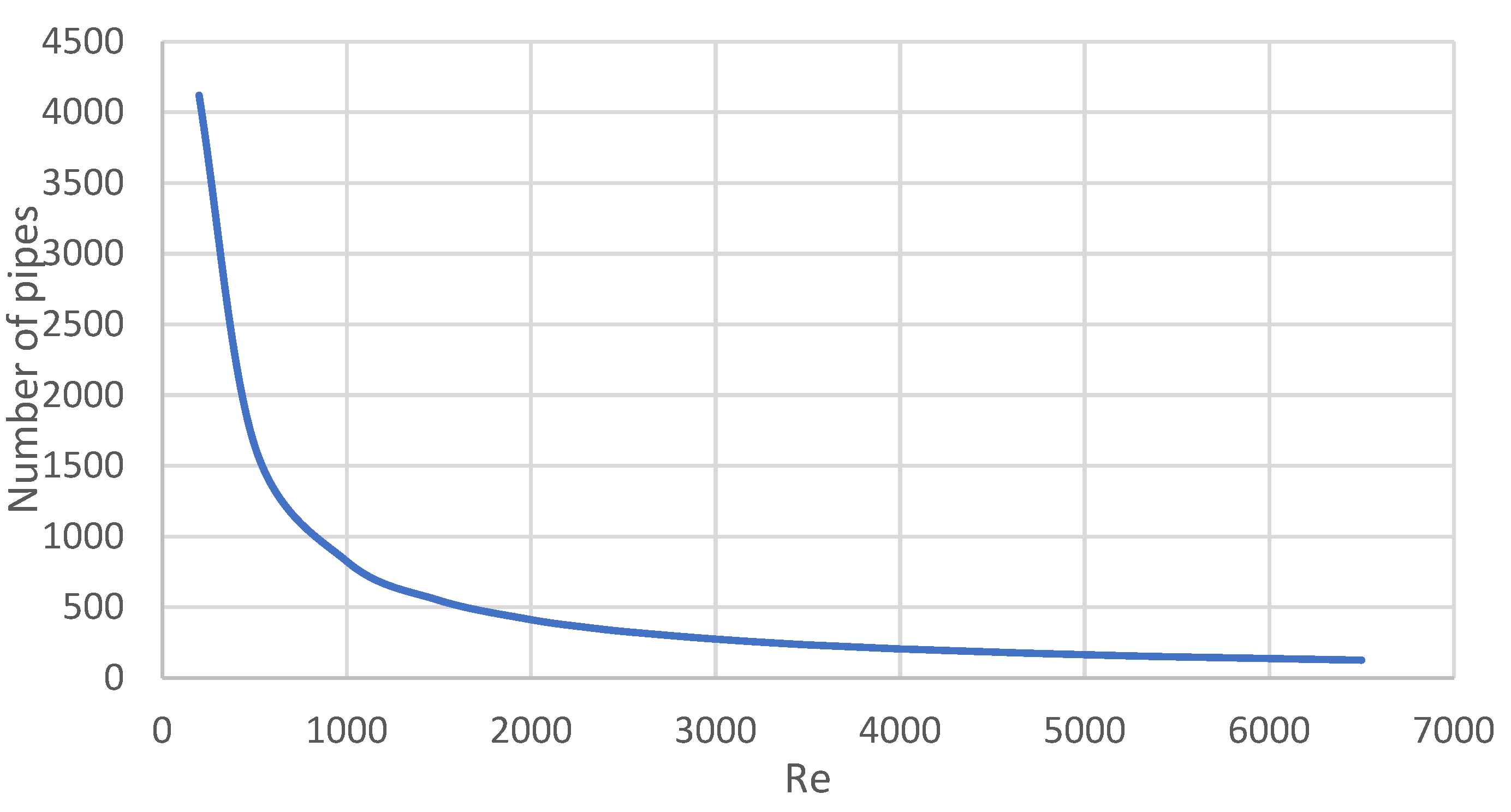
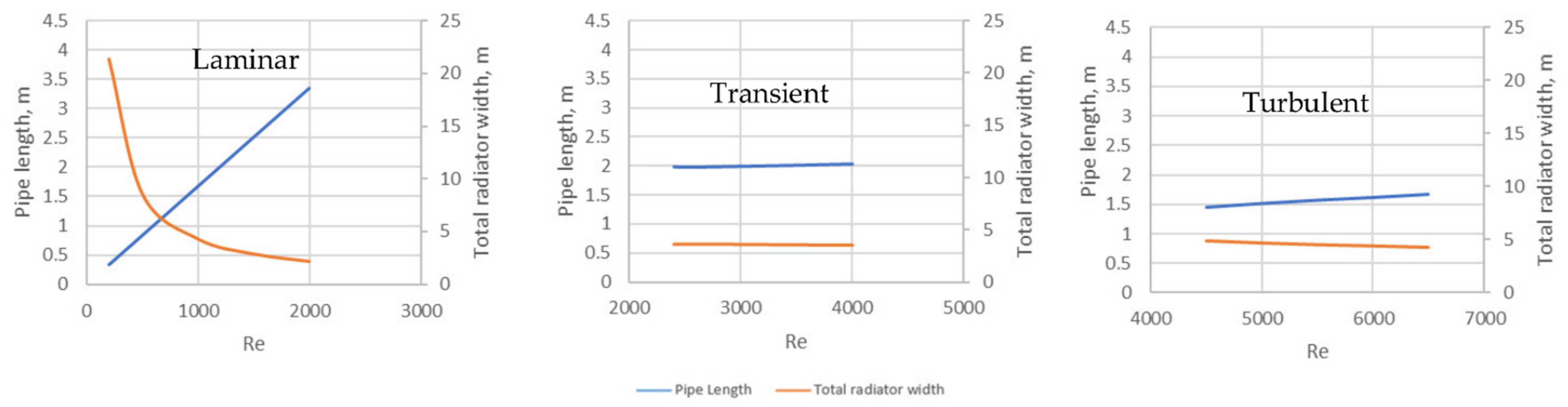
. The results for a pipe of a diameter
d = 2.0 mm are shown in
Figure 3,
Figure 4 and
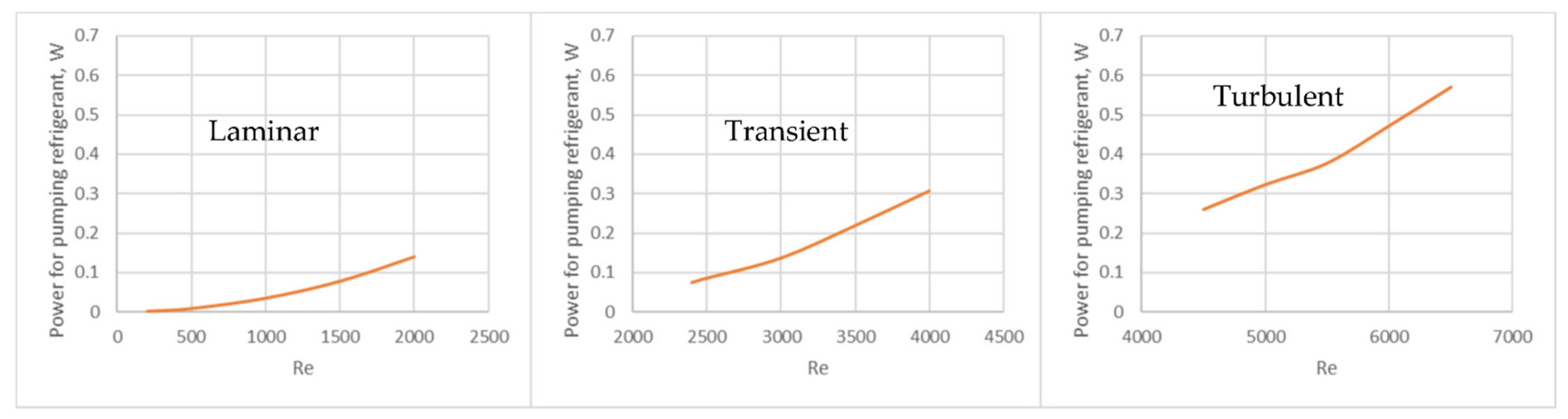
Figure 5. With a decrease in the refrigerant flow rate, the number of pipes increases and, consequently, the total width of the radiator, while the length of the pipe and the pumping power decrease. During a transitional flow (2300 <
Re < 4000), the value of the
Nu number increases, the heat rejection from the refrigerant increases, which consequently affects the geometric dimensions of the radiator.
For a pipe with a diameter at , the following results were obtained:
Number of pipes: ;
Total width of the radiator:
Pipe length:
Power spent on pumping the refrigerant: .
It is worth noting that with an increase in the number of pipes, the dimensions of the distribution collectors of the radiator increase. This would increase the total hydraulic losses at the inlet and outlet of the pipes.
During turbulent flows (Re > 4000), the heat transfer from the refrigerant to the pipe walls increases, therefore providing the required specific heat radiation flux per unit area, and the width of the fin increases.
For the same pipe diameter at , the following results were obtained:
Number of pipes: ;
Total width of the radiator:
Pipe length:
Power spent on pumping the refrigerant: .
Analyzing the results, it can be seen that the number of pipes decreased. However, the power required to pump the refrigerant through the radiator increased to a high value which is unacceptable. The design can be significantly improved by increasing the fin width of the radiator
, and increasing the pipe diameter d, which leads to minimizing the power required to pump the refrigerant
(Option 2 in
Appendix A). For instance, the increase in diameter to
leads to the following results at
Number of pipes: ;
Total width of the radiator:
Total width of the radiation surface:
Pipe length: ;
Power spent on pumping the refrigerant: .
Similar calculations for liquid ammonia were carried out and the results were compared. During a laminar flow (
;
Nu = 3.66) and based on the given initial data, the fin width remains constant
. For the given initial data,
. The calculation results are shown in
Figure 6,
Figure 7 and
Figure 8.
For a pipe with a diameter at , the following results were obtained:
Number of pipes: ;
Total width of the radiator:
Pipe length: ;
Power spent on pumping the refrigerant: .
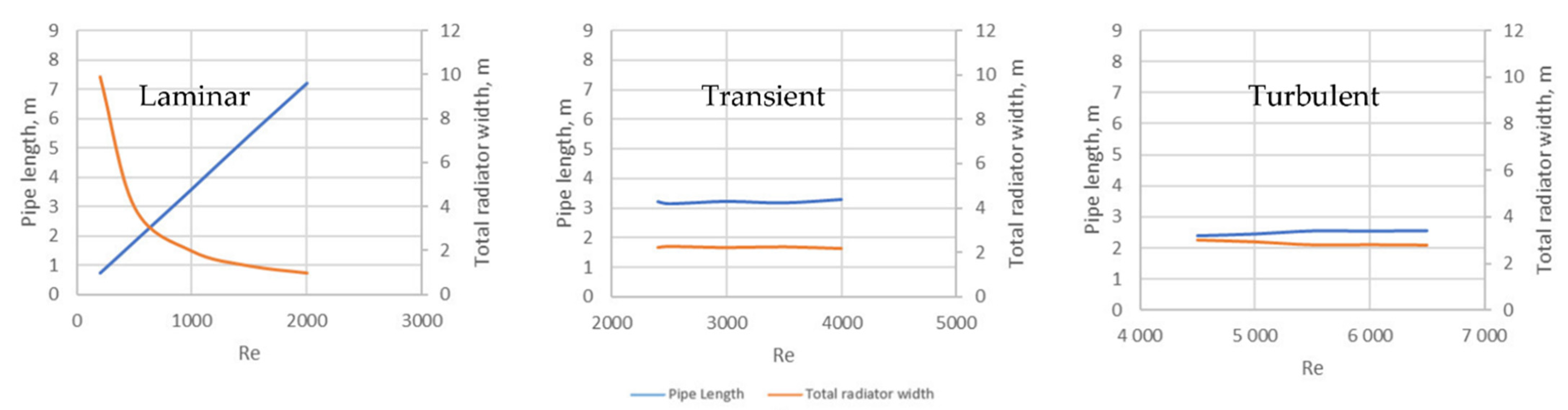
During turbulent flows, the heat transfer from the refrigerant to the pipe walls increases. At , the fin width increases (. The fin width allows the pipe diameter to increase.
The graphs of the dependences of the number of pipes
, pipe lengths
, as well as the total width of the radiation surface of the radiator
, and the power spent on pumping liquid ammonia
for various pipes diameters
d at
Re = 4500 are shown in
Figure 9,
Figure 10 and
Figure 11.
For a pipe with a diameter at , the following results were obtained:
Number of pipes: ;
Total width of radiator:
Total width of the radiation surface:
Pipe length: ;
Power spent on pumping the refrigerant: .
For a pipe with a diameter at , the following results were obtained:
Number of pipes: ;
Total width of radiator:
Total width of the radiation surface:
Pipe length:;
Power spent on pumping the refrigerant: .
Analyzing the results, it can be seen that although the length of the pipe has decreased by 2 times, the power for pumping the refrigerant increased; however, the values remain insignificant.
The conducted studies show that when using liquid ammonia, there are more possibilities for varying the geometric parameters of the radiator and the power for pumping the refrigerant can be significantly reduced. The final decision related to the suitable radiator design can be made based on the operating conditions of the lunar power plant.
Next, the influence of the thermodynamic properties of the refrigerant on the main geometrical parameters of the radiator is studied using the previously derived formulas (53)–(66) for two refrigerants:
From the formula (55) for a flow with the same
and given initial conditions
= 9.49;
1.12:
If pipes of the same diameter are used, then:
While using helium, the number of pipes will be 8.4 greater, compared to using liquid ammonia.
The fin width of the radiator during laminar flow (
;
Nu = 3.66):
where the radiation surface ratio:
The total heat transfer surface of the pipes:
To reject the required heat from the FPSE using helium as a refrigerant, the total heat radiation surface area of the pipes will be 3.9 times larger, i.e., the specific heat flux emitted by the pipe surface will be 3.9 times smaller, compared to using liquid ammonia. Therefore, the fin width is 3.9 times smaller when using helium, since less heat is radiated from the surface. Liquid ammonia allows the heat flux emitted by the radiator pipe section to increase. Therefore, it is possible to increase the width of the fin and reduce the length of the pipe. When using helium, the number of pipes and fin sections increases.
The results of the preliminary stage of calculation can be summed as follows. Taking into account the accepted assumptions, the total area of the radiator depends only on the temperature difference (). If the difference is provided, then the area and the specific heat flux will be the same using any refrigerant. The thermodynamic properties affect the design parameters of the radiator (Pipe diameter d; number of pipes ; pipe length , total radiator width and the pumping power of the refrigerant through the radiator ).
It has been established that the use of liquid ammonia as a refrigerant makes it possible to reduce the power for pumping the refrigerant through the radiator. The formulas (67)–(71) can also be used to compare other refrigerants.
After performing the first stage of the enhanced calculation method, we move onto the next stage and perform calculations using the previously developed method (two-dimensional model). A comparative analysis for laminar (
Re = 500) and turbulent (
Re = 4500) flows for two refrigerants—helium and liquid ammonia—was carried out. The comparison results are presented in
Table 2,
Table 3,
Table 4,
Table 5 and
Table 6 below.
The results of calculations using the previously developed two-dimensional radiator model by the authors confirmed the acceptable accuracy of the results obtained at the preliminary stage of the enhanced method presented in this work.
When considering a laminar flow (Re = 500), the maximum deviation in the radiator area is 0.83%, NR—1.12%. For turbulent flows (Re = 4500), the error increases:
- -
For liquid ammonia:
- -
For helium:
The conducted studies proved the effectiveness of the preliminary calculations using the derived formulas presented in this work. The enhanced method made it possible to effectively evaluate the capabilities of various refrigerants and choose the main design radiator parameters and the refrigerant flow regime in a less time-consuming process and with minimal deviations (<5%), compared to the previously developed two-dimensional radiator model by the authors.


