
Energy Dissipation Enhanced by Multiple Hinges in Bridge Piers with CFST Y-Shaped Fuses

Abstract
1. Introduction
2. Models and Methods
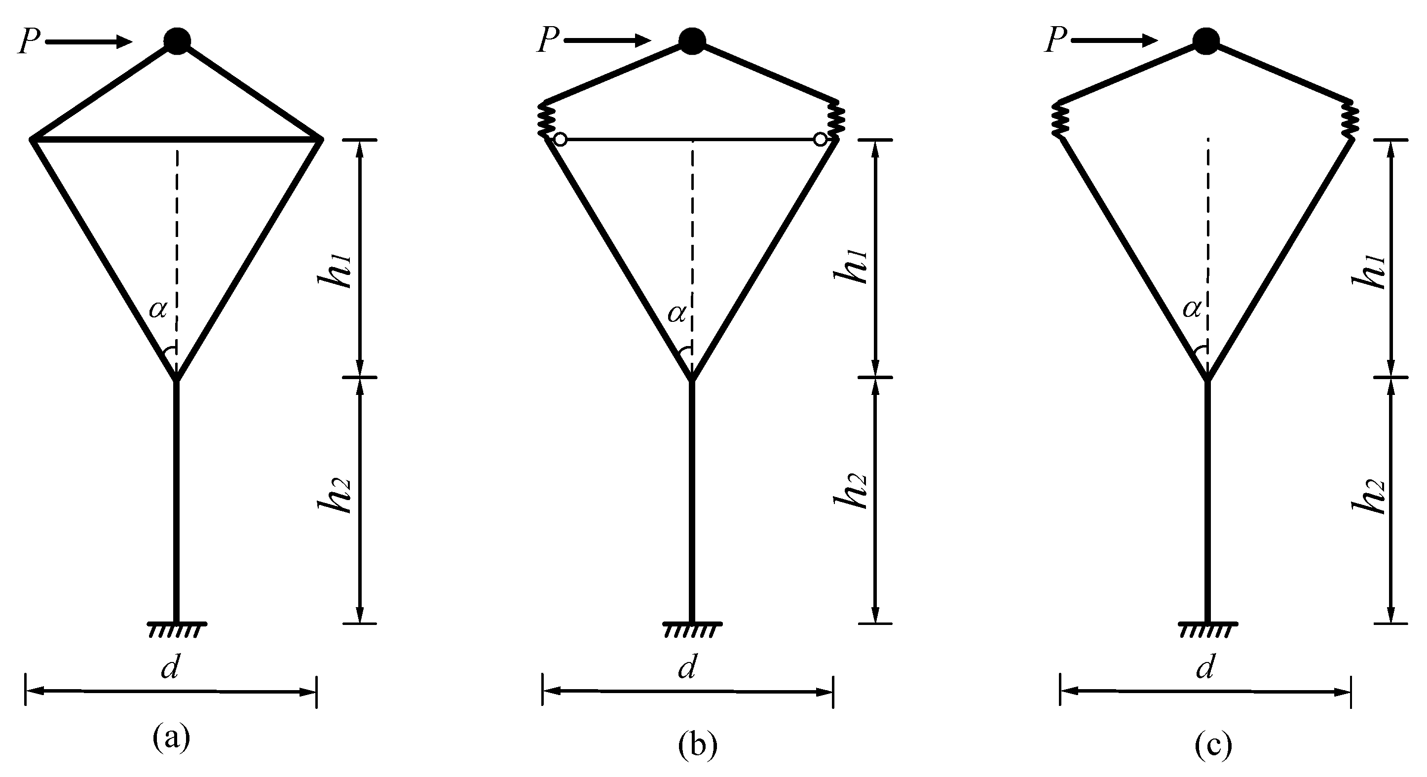
2.1. CFST-Y Bridge Pier Models
2.2. Pushover Methodology
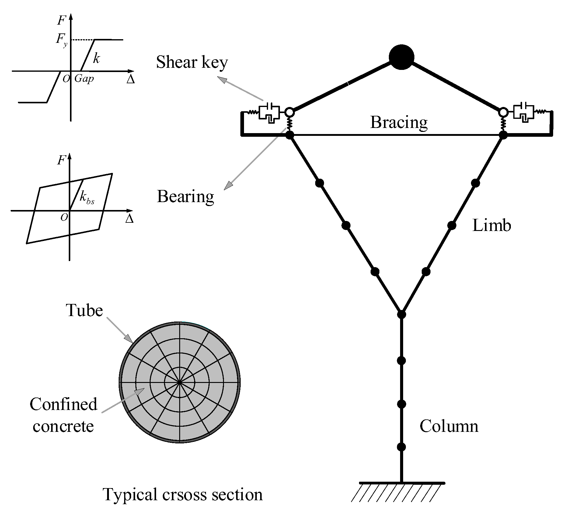
2.3. Numerical Models
3. Results and Discussion
3.1. Lateral Stiffnesses for Three Types of Y-Shaped Piers
3.2. Ductility Capacities for Piers with Different Pier–Deck Connections
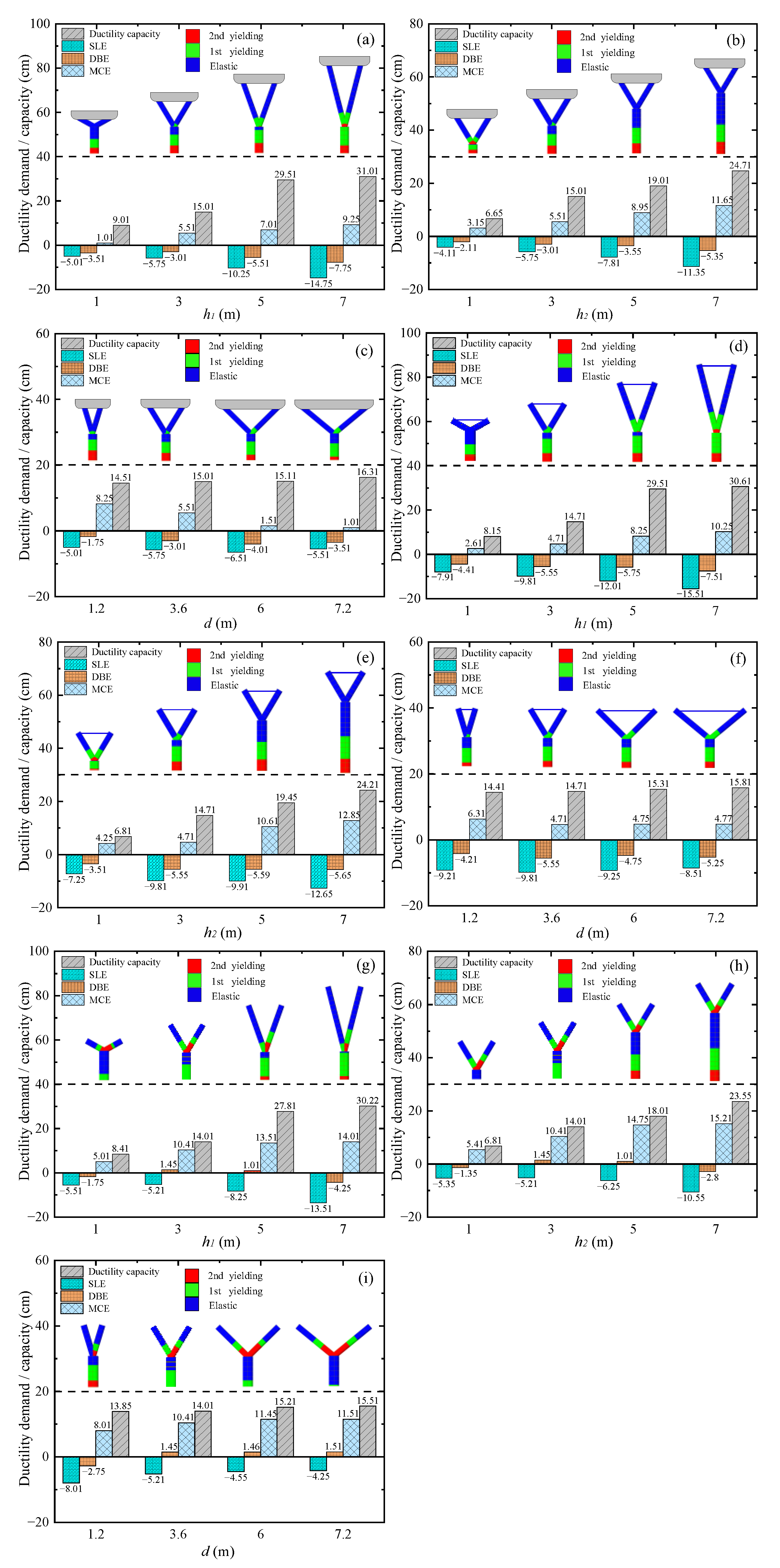
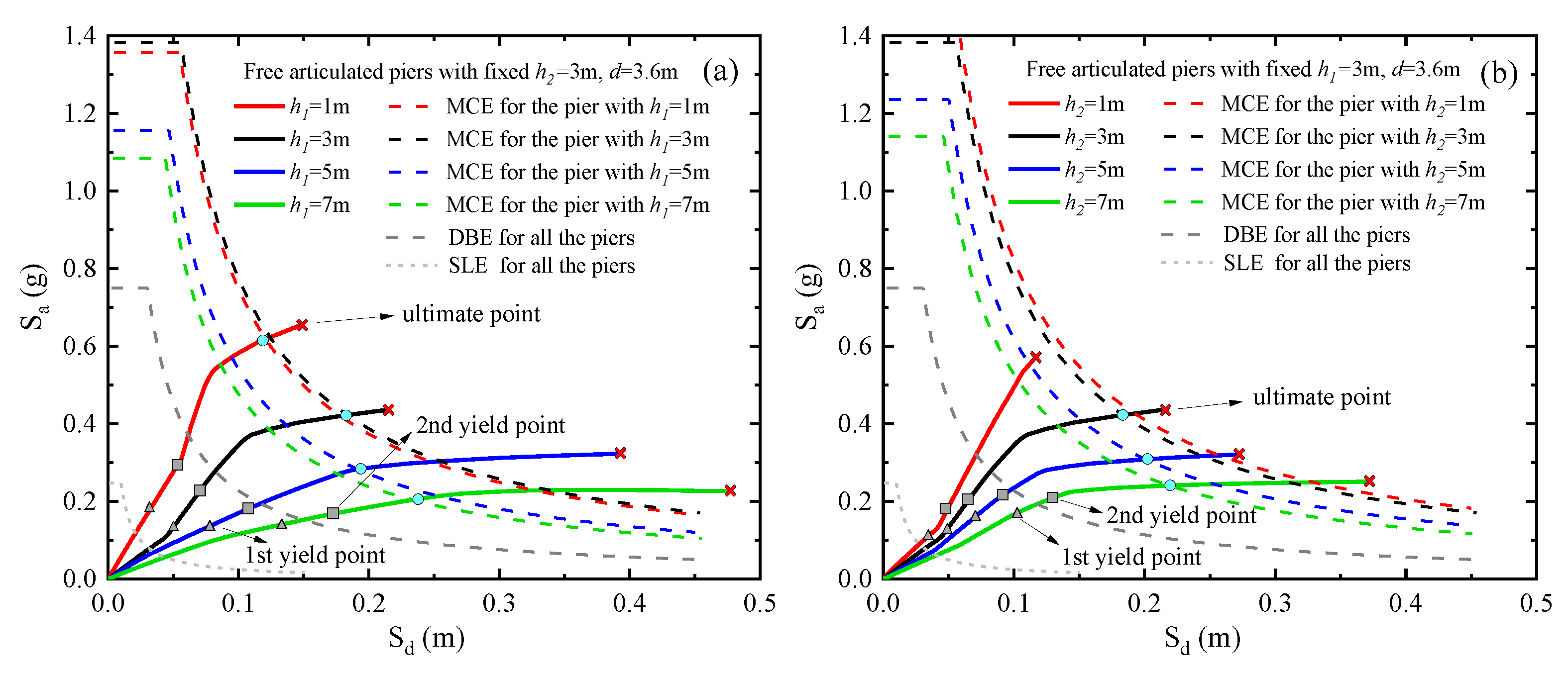
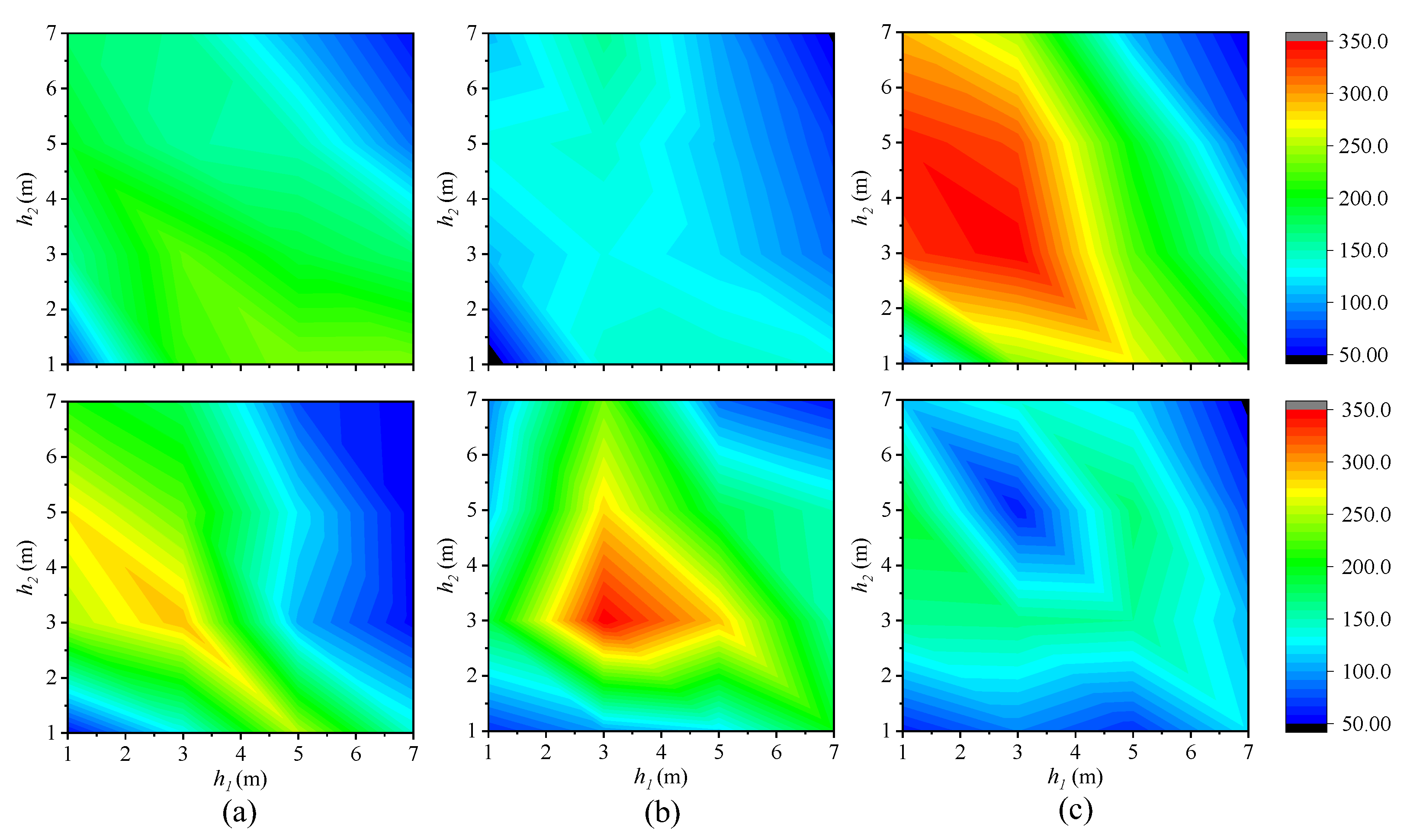
3.3. Ductility Capacities and Lateral Resistances for Piers with Different Structural Dimensions
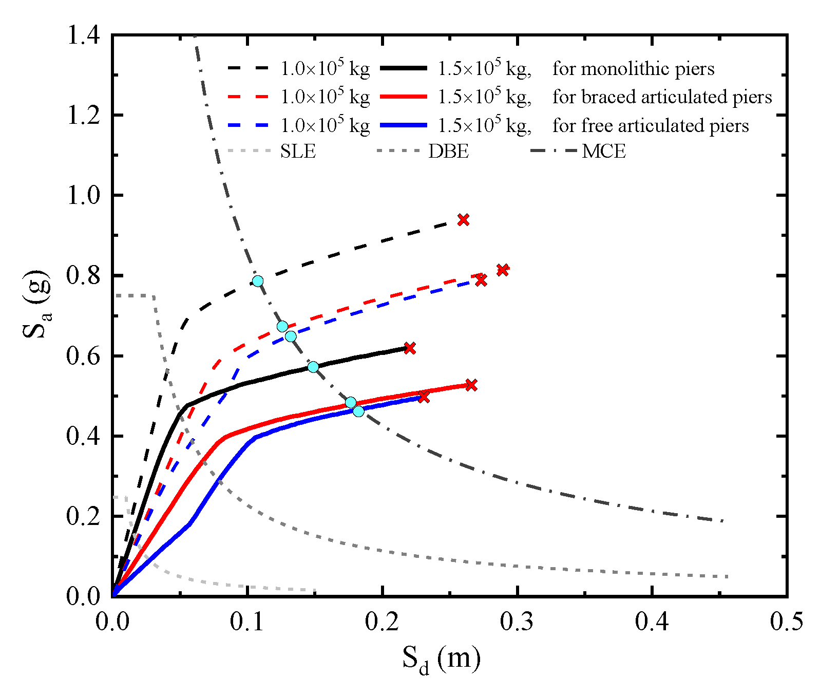
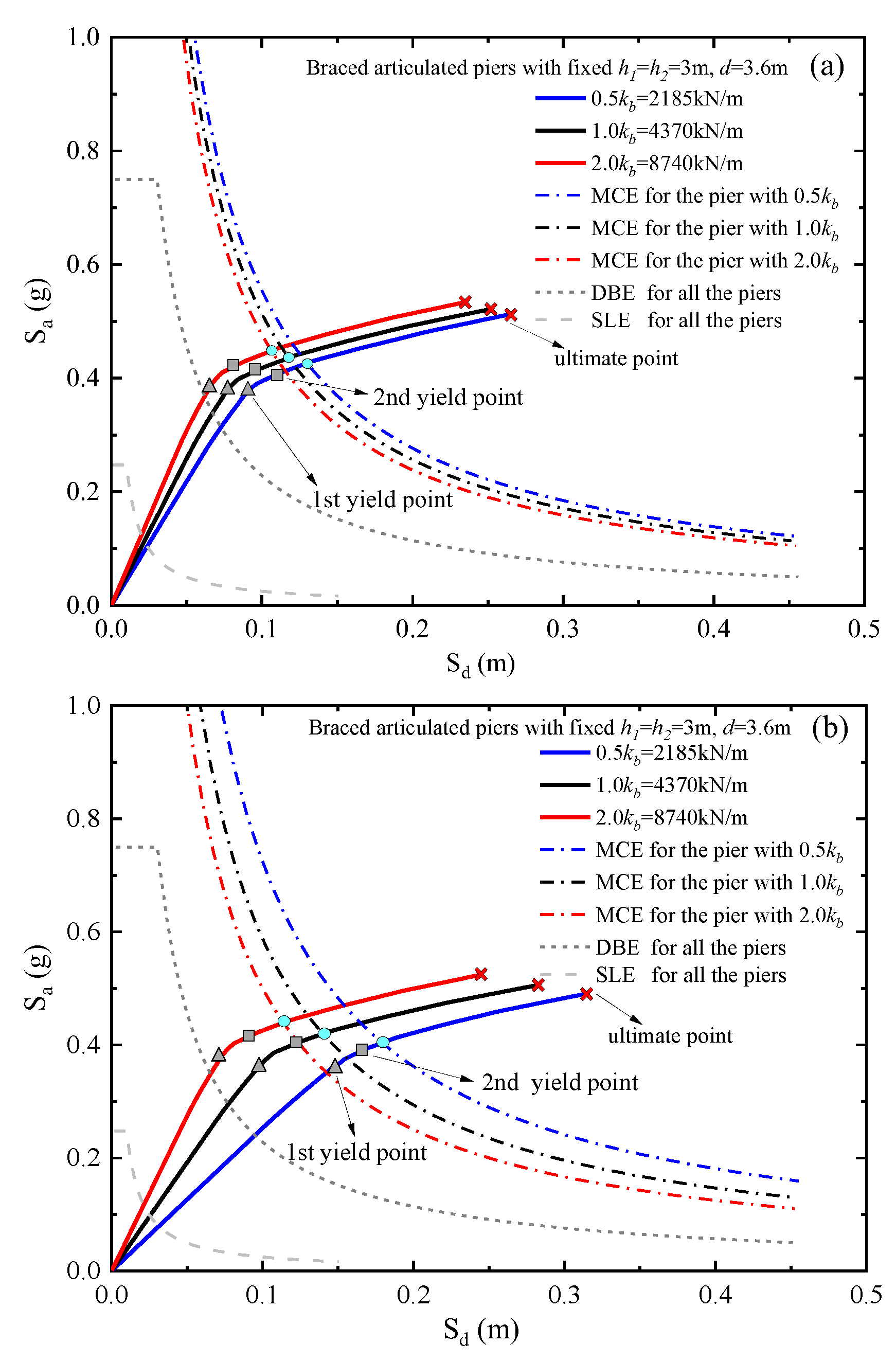
3.4. Ductility Demands at Different Deck Masses, Shear Limits, and Stiffnesses of Bearings
3.5. Energy Dissipation before and after the Expected Performance
4. Conclusions
- (1)
- The pier–deck connection and structural dimensions (h1, h2, and d) determine the lateral stiffnesses and yielding behaviors of the CFST Y-shaped piers that will further influence the lateral resistances and ductility capacities in bridges at the SLE, DBE, and MCE hazard levels.
- (2)
- On achieving the expected performance objectives, the ductility demands for all three types of piers increase with the deck mass. Particularly, for the braced and free articulated piers, the ductility demands increase with the shear limit but decrease with the shear stiffness of bearings.
- (3)
- The absorbed and residual energies before and after the expected performance can be utilized to evaluate the ductility exploitation and performance redundancy in CFST-Y piers. The enhanced absorbed energies before the MCE performance were observed in the free articulated piers where the extra energies were dissipated by multiple hinges formed in CFST Y-shaped fuses.
Author Contributions
Funding
Institutional Review Board Statement
Informed Consent Statement
Data Availability Statement
Conflicts of Interest
Nomenclature
| CFST | concrete-filled steel tubular | |
| RC | reinforced concrete | |
| CFST-Y | CFST Y-shaped | |
| SDF | single-degree-of-freedom | |
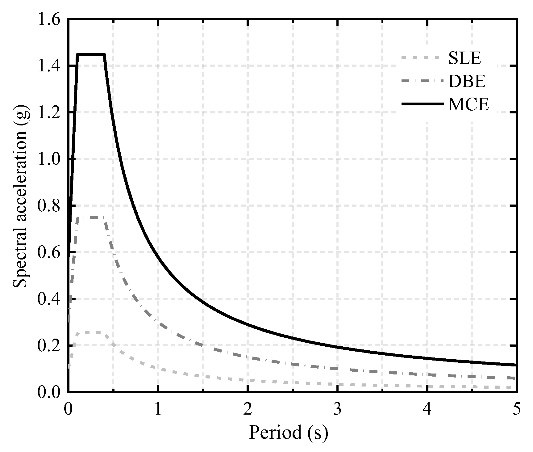
| Sa | spectral acceleration | |
| Sd | spectral displacement | |
| ADRS | Acceleration Displacement Response Spectrum | |
| SLE | Service Level Earthquake | |
| DBE | Design Based Earthquake | |
| MCE | Maximum Credible Earthquake | |
| IO | Immediate Occupancy | |
| LS | Life Safety | |
| CP | Collapse Prevention | |
| h | total pier height | |
| h1 | limb height | |
| h2 | column height | |
| d | center-to-center spacing between the limb tops | |
| Es | elastic modulus of Q345 steel | |
| α | inclined angle between one limb and the vertical line | |
| I1 | moment of inertia of limb | |
| I2 | moment of inertia of column | |
| P | equivalent lateral static loading | |
| m | effective mass of bridge deck | |
| kp1 | lateral stiffness of the monolithic piers | |
| kp2 | lateral stiffness of the braced articulated piers | |
| kp3 | lateral stiffness of the free articulated piers | |
| kc1 | lateral stiffness of the upper portion of the Y-shaped pier | |
| kc2 | lateral stiffness of the lower portion of the Y-shaped pier | |
| E | equivalent elastic modulus of CFSTs | |
| kb | shear stiffness of bearings in a pier system | |
| kbs | shear stiffness of a single bearing | |
| kl1 | lateral stiffness of the left limb | |
| kl2 | lateral stiffness of the right limb | |
| λ | ratio of the lateral seismic force to the equivalent gravity of deck | |
| ke1 | equivalent lateral stiffness of the left limb-bearing systems | |
| ke2 | equivalent lateral stiffness of the left limb-bearing systems | |
| Δu | post-yielding displacement capacity | |
| Δ0 | ductility demand | |
| uu | ultimate deck displacement | |
| uy | the second yielding displacement | |
| u0 | displacement demand at a given earthquake level | |
| Δu1 | ductility capacity of the monolithic pier | |
| Δu2 | ductility capacity of the braced articulated pier | |
| Δu3 | ductility capacity of the free articulated pier |
References
- Yang, S.; Huang, D. Aesthetic considerations for urban pedestrian bridge design. J. Archit. Eng. 1997, 3, 3–8. [Google Scholar] [CrossRef]
- Priestley, M. Performance based seismic design. Bull. N. Z. Soc. Earthq. 2000, 33, 325–346. [Google Scholar] [CrossRef]
- Priestley, M.J.N.; Calvi, G.M.; Kowalsky, M.J. Direct displacement-based seismic design of structures. In Proceedings of the NZSEE Conference, Wellington, New Zealand, 30 March–1 April 2007; pp. 1–23. [Google Scholar]
- D’Amato, M.; Braga, F.; Gigliotti, R.; Kunnath, S.; Laterza, M. A numerical general-purpose confinement model for non-linear analysis of R/C members. Comput. Struct. 2012, 102–103, 64–75. [Google Scholar] [CrossRef]
- Guney, O.; Saatcioglu, M. Confinement of concrete columns for seismic loading. Struct. J. 1987, 84, 308–315. [Google Scholar]
- Stephens, M.T.; Lehman, D.E.; Roeder, C.W. Seismic performance modeling of concrete-filled steel tube bridges: Tools and case study. Eng. Struct. 2018, 165, 88–105. [Google Scholar] [CrossRef]
- Chacon, R.; Mirambell, E.; Real, E. Strength and ductility of concrete-filled tubular piers of integral bridges. Eng. Struct. 2013, 46, 234–246. [Google Scholar] [CrossRef]
- Elremaily, A.; Azizinamini, A. Behavior and strength of circular concrete-filled tube columns. J. Constr. Steel. Res. 2002, 58, 1567–1591. [Google Scholar] [CrossRef]
- Marson, J.; Bruneau, M. Cyclic testing of concrete-filled circular steel bridge piers having encased fixed-based detail. J. Bridge Eng. 2004, 9, 14–23. [Google Scholar] [CrossRef]
- Han, L.-H.; Li, W.; Bjorhovde, R. Developments and advanced applications of concrete-filled steel tubular (CFST) structures: Members. J. Constr. Steel. Res. 2014, 100, 211–228. [Google Scholar] [CrossRef]
- Roeder, C.W.; Stephens, M.T.; Lehman, D.E. Concrete filled steel tubes for bridge pier and foundation construction. Int. J. Steel Struct. 2018, 18, 39–49. [Google Scholar] [CrossRef]
- Wang, J.; Kunnath, S.; He, J.; Xiao, Y. Post-Earthquake Fire Resistance of Circular Concrete Filled Steel Tubular Columns. J. Struct. Eng. 2020, 146, 1–13. [Google Scholar] [CrossRef]
- Chung, Y.-S.; Park, C.K.; Meyer, C. Residual seismic performance of reinforced concrete bridge piers after moderate earthquakes. ACI. Struct. J. 2008, 105, 87–95. [Google Scholar]
- Bertero, R.D.; Bertero, V.V. Redundancy in earthquake-resistant design. J. Struct. Eng. 1999, 125, 81–88. [Google Scholar] [CrossRef]
- Paulay, T.; Priestley, M. Seismic Design of Reinforced Concrete and Masonry Buildings; John Wiley & Sons, Inc.: Hoboken, NJ, USA, 1992; pp. 95–157. [Google Scholar]
- Bovo, M.; Savoia, M.; Praticò, L. Seismic Performance Assessment of a Multistorey Building Designed with an Alternative Capacity Design Approach. Adv. Civ. Eng. 2021, 2021, 5178065. [Google Scholar] [CrossRef]
- Zhang, C.; Tian, Y. Simplified performance-based optimal seismic design of reinforced concrete frame buildings. Eng. Struct. 2019, 185, 15–25. [Google Scholar] [CrossRef]
- Kia, S.M.; Yahyai, M. Relationship between local and global ductility demand in steel moment resisting frames. In Proceedings of the World Conference on Earthquake Engineering WCEE, Vancouver, BC, Canada, 1–6 August 2004. [Google Scholar]
- Fajfar, P. Capacity spectrum method based on inelastic demand spectra. Earthq. Eng. Struct. D 1999, 28, 979–993. [Google Scholar] [CrossRef]
- Yang, T.Y.; Tung, D.P.; Li, Y. Equivalent energy design procedure for earthquake resilient fused structures. Earthq. Spectra. 2018, 34, 795–815. [Google Scholar] [CrossRef]
- Zou, X.K.; Chan, C.M. Optimal seismic performance-based design of reinforced concret-e buildings using nonlinear pushover analysis. Eng. Struct. 2005, 27, 1289–1302. [Google Scholar] [CrossRef]
- Ghobarah, A. Performance-based design in earthquake engineering: State of development. Eng. Struct. 2001, 23, 878–884. [Google Scholar] [CrossRef]
- Cardone, D.; Dolce, M.; Palermo, G. Direct displacement-based design of seismically isolated bridges. Bull. Earthq. Eng. 2009, 7, 391–410. [Google Scholar] [CrossRef]
- Guo, W.; Hu, Y.; Liu, H.; Bu, D. Seismic performance evaluation of typical piers of China’s high-speed railway bridge line using pushover analysis. Math. Probl. Eng. 2019, 2019, 95147691. [Google Scholar] [CrossRef]
- Wang, P.-H.; Chang, K.-C.; Dzeng, D.-C.; Lin, T.-K.; Hung, H.-H.; Cheng, W.-C. Seismic evaluation of reinforced concrete bridges using capacity-based inelastic displacement spectra. Earthq. Eng. Struct. Dyn. 2021, 50, 1845–1863. [Google Scholar] [CrossRef]
- Sadeghi, M.A.; Yang, T.Y.; Bagatini-Cachuço, F.; Pan, S. Seismic design and performance evaluation of controlled rocking dual-fused bridge system. Eng. Struct. 2020, 212, 110467. [Google Scholar] [CrossRef]
- Liu, Q.F.; Zhu, S.M.; Yu, W.S.; Wu, X.; Song, F.; Ren, X. Ground Motion Frequency Insensit-ivity of Bearing Supported Pedestrian Bridge with Viscous Dampers. KSCE. J. Civ. Eng. 2021, 25, 2662–2673. [Google Scholar] [CrossRef]
- JTG/T 2231-01-2020; Specifications for Seismic Design of Highway Bridges. Chongqing Communications Research Institute: Chongqing, China; People’s Communication Publishing: Beijing, China, 2020.
- FEMA. NEHRP Guidelines for the Seismic Rehabilitation of Buildings; FEMA-273; Applied Technology Council for the Building Seismic Safety Council: Washington, DC, USA, 1997. [Google Scholar]
- Krawinkler, H.; Seneviratna, G. Pros and cons of a pushover analysis of seismic performance evaluation. Eng. Struct. 1998, 20, 452–464. [Google Scholar] [CrossRef]
- Calvi, G.M.; Pavese, A. Conceptual design of isolation systems for bridge structures. J. Earthq. Eng. 1997, 1, 193–218. [Google Scholar] [CrossRef]
- ATC-40; Seismic Evaluation and Retrofit of Concrete Buildings. Applied Technology Council: Redwood City, CA, USA, 1996.
- Fajfar, P. A nonlinear analysis method for performance-based seismic design. Earthq. Spectra. 2000, 16, 573–592. [Google Scholar] [CrossRef]
- Lagaros, N.D.; Fragiadakis, M. Evaluation of ASCE-41, ATC-40 and N2 static pushover methods based on optimally designed buildings. Soil. Dyn. Earthq. Eng. 2011, 31, 77–90. [Google Scholar] [CrossRef]
- McKenna, F. Open System for Earthquake Engineering Simulation. OpenSees. Available online: https://opensees.berkeley.edu/ (accessed on 3 July 2020).
- Midas/Civil. Nonlinear FE Software for Bridge Design & Analysis; Midas Information Technology Co., Ltd.: Seongnam, Korea, 2000. [Google Scholar]
- Scott, B.D.; Park, R.; Priestley, M.J.N. Stress-Strain Behavior of Concrete Confined by Overlapping Hoops at Low and High Strain Rates. J. Proc. 1982, 79, 13–27. [Google Scholar]
- Susantha, K.; Ge, H.; Usami, T. Uniaxial stress-strain relationship of concrete confined by various shaped steel tubes. Eng. Struct. 2001, 23, 1331–1347. [Google Scholar] [CrossRef]
- JTJ 663-2006; Series of Elastomeric Pad Bearings for Highway Bridges. CCCC Highway Consultants Co., Ltd. People’s Communications Publishing: Beijing, China, 2007.
- GB50011-2010; Code for Seismic Design of Buildings. China Ministry of Construction. China Architecture & Building Press: Beijing, China, 2010.
- Fan, L.C.; Zhuo, W.D. Ductility Seismic Design of Bridges; People’s Communication Publishing: Beijing, China, 2001. [Google Scholar]
- Sigurdardottir, D.H.; Glisic, B. Measures of Structural Art: A Case Study Using Streicker Bridge; Princeton University: Princeton, NJ, USA, 2013; pp. 275–284. [Google Scholar]
- Abey, E.T.; Somasundaran, T.P.; Sajith, A.S. Significance of elastomeric bearing on seismic response reduction in bridges. In Advances in Structural Engineering; Springer: New Delhi, India, 2015; pp. 1339–1352. [Google Scholar]


| h (m) | h1 (m) | h2 (m) | d (m) | kp1 (103 kN/m) | Δu1 (cm) | kp2 (103 kN/m) | Δu2 (cm) | kp3 (103 kN/m) | Δu3 (cm) |
|---|---|---|---|---|---|---|---|---|---|
| 4 | 1 | 3 | 3.6 | 93.09 | 9.01 | 7.97 | 8.15 | 7.71 | 8.41 |
| 6 | 3 | 3 | 3.6 | 20.83 | 15.01 | 6.91 | 14.71 | 5.90 | 14.01 |
| 8 | 5 | 3 | 3.6 | 7.05 | 29.51 | 4.88 | 29.51 | 4.39 | 27.81 |
| 10 | 7 | 3 | 3.6 | 3.11 | 31.01 | 3.48 | 30.61 | 2.66 | 30.22 |
| 4 | 3 | 1 | 3.6 | 39.40 | 6.65 | 8.19 | 6.81 | 6.81 | 6.81 |
| 6 | 3 | 3 | 3.6 | 20.83 | 15.01 | 6.91 | 14.71 | 5.90 | 14.01 |
| 8 | 3 | 5 | 3.6 | 10.87 | 19.01 | 5.30 | 19.45 | 4.68 | 18.01 |
| 10 | 3 | 7 | 3.6 | 6.06 | 24.71 | 3.82 | 24.21 | 3.49 | 23.55 |
| 6 | 3 | 3 | 1.2 | 21.95 | 14.51 | 6.97 | 14.41 | 6.18 | 13.85 |
| 6 | 3 | 3 | 3.6 | 20.83 | 15.01 | 6.91 | 14.71 | 5.90 | 14.01 |
| 6 | 3 | 3 | 6.0 | 19.16 | 15.11 | 6.84 | 15.31 | 4.91 | 15.21 |
| 6 | 3 | 3 | 7.2 | 18.29 | 16.31 | 6.80 | 15.81 | 4.58 | 15.51 |
Publisher’s Note: MDPI stays neutral with regard to jurisdictional claims in published maps and institutional affiliations. |
© 2022 by the authors. Licensee MDPI, Basel, Switzerland. This article is an open access article distributed under the terms and conditions of the Creative Commons Attribution (CC BY) license (https://creativecommons.org/licenses/by/4.0/).
Share and Cite
Liu, Q.; Guo, Z.; Wu, X.; Lu, K.; Ren, X.; Xiao, J. Energy Dissipation Enhanced by Multiple Hinges in Bridge Piers with CFST Y-Shaped Fuses. Symmetry 2022, 14, 2371. https://doi.org/10.3390/sym14112371
Liu Q, Guo Z, Wu X, Lu K, Ren X, Xiao J. Energy Dissipation Enhanced by Multiple Hinges in Bridge Piers with CFST Y-Shaped Fuses. Symmetry. 2022; 14(11):2371. https://doi.org/10.3390/sym14112371
Chicago/Turabian StyleLiu, Qunfeng, Zhaoyang Guo, Xing Wu, Kaile Lu, Xiang Ren, and Jialong Xiao. 2022. "Energy Dissipation Enhanced by Multiple Hinges in Bridge Piers with CFST Y-Shaped Fuses" Symmetry 14, no. 11: 2371. https://doi.org/10.3390/sym14112371
APA StyleLiu, Q., Guo, Z., Wu, X., Lu, K., Ren, X., & Xiao, J. (2022). Energy Dissipation Enhanced by Multiple Hinges in Bridge Piers with CFST Y-Shaped Fuses. Symmetry, 14(11), 2371. https://doi.org/10.3390/sym14112371