Article

Asymmetrical Damage Aspects Based Investigations on the Disc Brake of Long-Range UAVs through Verified Computational Coupled Approaches

by
Vijayanandh Raja
1,
Raj Kumar Gnanasekaran
1,
Parvathy Rajendran
2,3,
Aiffah Mohd Ali
2,*,
Raffik Rasheed
4,
Hussein A. Z. AL-bonsrulah
5,6 and
Mohammed Al-Bahrani
7,8
1
Department of Aeronautical Engineering, Kumaraguru College of Technology, Coimbatore 641049, Tamil Nadu, India
2
School of Aerospace Engineering, Universiti Sains Malaysia, Nibong Tebal 14300, Penang, Malaysia
3
Faculty of Engineering & Computing, First City University College, Bandar Utama 47800, Selangor, Malaysia
4
Department of Mechatronics Engineering, Kumaraguru College of Technology, Coimbatore 641049, Tamil Nadu, India
5
Al-Amarah University College, Maysan 62001, Iraq
6
Iraqi Ministry of Oil, Midland Refineries Company, Najaf Refinery, Najaf 54001, Iraq
7
School of Engineering, Computing and Mathematics, University of Plymouth, Plymouth PL4 8AA, UK
8
Chemical Engineering and Petroleum Industries Department, Al-Mustaqbal University College, Babylon 51001, Iraq
*
Author to whom correspondence should be addressed.
Symmetry 2022, 14(10), 2035; https://doi.org/10.3390/sym14102035
Submission received: 9 August 2022 / Revised: 21 September 2022 / Accepted: 22 September 2022 / Published: 29 September 2022

Abstract

:
In recent years, the use of unmanned aerial vehicles (UAVs) has increased significantly. Asymmetrical factors, or frictional studies on the disc brake of UAVs, are one of the safety considerations taken into consideration during the design process because UAVs and their components have been built with the best safety in mind. This study focuses on choosing the optimal material for a UAV’s disc brake by using transient structural and thermal models. In order to compare the asymmetry-based frictional force produced by the two ways; the processes used in the transient simulation are validated using pin-on-disc (POD) testing. The foundation for this validation investigation is a metal matrix composite made of an aluminum alloy, and the basis tool is an ASTM G99-based computational test specimen. Steel-EN24 and carbon ceramic matrix composites testing are expanded using the same POD tests. A range of 3 percent to 8 percent error rates is found. As a result, the calculation techniques are applied to the UAV’s disc brake after they have proven to be trustworthy. This fixed-wing UAV’s extensions have a 5 kg payload capacity. The weight, avionics components, tire dimensions, and disc brake dimensions of the other UAV design parts are calculated using analytical formulas. The final designs are made using CATIA as a result. The grid convergence experiment is organized using a traditional finite element analysis tool. Finally, at its maximum rotational speed, a UAV’s disc brake is put through asymmetrical friction testing based on structural and thermal consequences. The correct materials for critical applications, such as carbon fiber-woven-wet-based reinforced polymer and Kevlar unidirectional-49-based reinforced polymer composites for changing rotating speeds, have now been made possible by fixed-wing UAVs.

1. Introduction

The authors build on prior research by analyzing the frictional characteristics of disc brakes used on fixed-wing unmanned aerial vehicles (FWUAVs). An essential part of a disc brake is the wheel hub, which houses the caliper, knuckle, piston, lining puck, gasket, brake pad, and other smaller parts. The disc is kept in place against the piston with the use of pins, spring plates, and a friction pad. When used in conjunction with the aforementioned components, the disc brake bleeding valve and bleeding bolt further enhance stopping power. Every cylinder has a rubber ring that seals the piston to the cylinder. The wheel hub has been fitted with rotors. By applying force through the rudder pedals to the brakes, the kinetic energy might be converted into thermal energy [1]. Due to the high likelihood of failure induced by friction, it is anticipated that increased-resisting materials will deposit between the internal frictional connections of the UAV’s disc brake. When landing an airplane, disc brakes have long been the standard. Landings on very small runways have been made possible thanks to the disc brake. The disc brake and brake pad may have been major contributors to the inconsistent braking encountered in high-velocity zones due to the UAV’s wide range of operating circumstances, which include 250 rotational speed per minute (RPM) during takeoff and 3500 RPM while landing. Since a disc brake’s longevity is tied to the materials and its qualities, this study compares and contrasts the traditional selection approach with the thorough selection of appropriate material for unmanned aerial vehicle (UAV) disc brakes under all loads. For this reason, there has been a surge in interest in this topic as researchers consider the possibility of replacing alloys with lightweight composites.

1.1. Literature Survey

Typically, a literature review directs the research and its solution strategies in the right order. The objective of this study was to collect information regarding the design of an FWUAV and its disc brake, as well as validation approaches for both transient structural and thermal computations. Relevant works are as follows: Using computational transient structural analysis, G. R. Kumar et al. [1] in 2020 conducted comparative research on rotating discs made from a variety of lightweight composite materials. With the aid of the ANSYS Tool, the polymer matrix composites (PMC) were primarily examined at various rotational speeds. In addition, the SiC-based improvement in PMCs was implemented, resulting in the same computational analyses. For validation, the POD (pin-on-disc) relevant experimental test was utilized and frictional forces from POD and computational results were compared. This inquiry reveals the following noteworthy data: material properties of all composites, boundary conditions placed on computational structural calculations, prototype preparations of PMC, and experimental procedures of POD. In 2018, Yash Vashi [2] examined the disc brake’s thermal and structural assessments. Initially, he employed metal matrix composites (MMC) in the disc brake, which paved the way for the current studies to utilize other MMCs. MMCs are intended to be implemented in one location as part of the ongoing research that is the validation of computational procedures derived from MMC aluminum alloy. Yash Vashi’s computational techniques and boundary conditions are supported in this work, particularly the mesh generation types, displacement types, and RPM of the UAV’s disc brake, which are mostly sound. According to this UAV’s specifications, the analytical approach outlined in the article [2] for the building of the aircraft’s disc brake was adjusted and improved. Consequently, the singular UAV and its disc brake were encased [2].
The FWUAV was built using the conventional analytical approach by Aliyu BharKisabo et al. [3] in 2017 for use in surveillance applications. Particularly, the confidence to apply the current work was gained by deriving and employing the relationship between the total weight of the UAV and the payload weight of the UAV. This study primarily observes and intends to execute the other standard equations, including wing planform area, aspect ratio, wing loading, wingspan, and chord length. The analytical method used in this article [3] has been finalized to design the wing and fuselage configuration of this current UAV. Preliminary design calculations on UAVs were performed by Álvaro Gómez-Rodríguez et al. [4] in 2018, from which numerous relations were established for use in the design process. The most important relationships discovered were those between the wing area and the maximum take-off weight of the UAV, the loading on the span and the total take-off weight, the area of the horizontal tailplane and the wing area of the UAV, the area of the vertical tail planform and the maximum take-off weight of the UAV, and the moment arm of the vertical tail-plane and the moment arm of the horizontal tail-plane. Due to difficulties in building the FWUAV’s vertical and horizontal tails, the derived relationships between the UAV’s horizontal tailplane area and its wing area, its vertical tail planform area and its maximum take-off weight, its vertical tail-plane moment arm, and its horizontal tail-plane moment arm are used here [4]. Based on their research and computations, Álvaro Gómez-Rodríguez et al. [4] determined the empennage for this FWUAV. Building the landing gear and its wheel disc brakes is another challenging aspect of this work. This paper referred to the standard equations found in Daniel Raymer’s book on airplane design [5]. Extracted linkages include those between wheel diameter and thickness, wheel height and thickness, and wheel design versus disc brake design parameters. Daniel Raymer [5] compiled the formulas used to build the disc brake used in this study.
Weight and resistance to thermal stress induction are prioritized in this work as selection criteria for lightweight materials in the UAV arena. For this reason, the thermal outcome is best calculated analytically and computationally with the aid of typical boundary conditions and beginning variables such as thermal conductivity, thermal diffusivity, and specific heat capacity. All of these basic thermal parameters for the imposed lightweight materials are culled from widely available literature reviews, wherein references to articles [6,7,8,9] on the required thermal characteristics of carbon fiber-reinforced polymer (CFRP) were made. We cited [10] for information on the thermal properties of glass fiber-reinforced polymer (GFRP), and [11,12] for information on the thermal characteristics of kevlar fiber-reinforced polymer (KFRP). And the publication [13] provides the required thermal characteristics of SiC related to CFRP composites.

1.2. Related Inferred Terminologies

The review of the literature showed that steel alloys were often used in aircraft disc brakes because they could stand up to a lot. Steel was used in the disc brake, which made the aircraft a little bit heavier. The gyro effect is well known in the aerospace industry as a factor that shows how important it is for a design to be light and how there are trade-offs when more mass is added. Since weight is so important, adding just 1 kg to the plane would cause 10 problems. That is why it is important to cut back on the weight gain caused by steel alloys, even if it is just a little bit. Since CFRP and its advanced composites are already used in rotating environments in the automotive industry, it makes sense that the aerospace industry will do the same. This study is mostly about how composites can be used in the disc brakes of UAVs. The goal is to find a good composite based on the ability to create low frictional stress.
Moreover, these surveys showed that computer-aided engineering simulations were used for the vast majority of complex analyses, while experimental tests were used for the vast majority of basic studies. So, the same methods will be used in this study from different fields. Using computational coupled transient structural and thermal analyses, this material optimization is planned to be carried out on the UAV’s disc brake. Planned the execution of the grid convergence test to validate computational procedures and the completion of verifications based on the pin-on-disc (POD) experimental test to further check the reliability of the imposed computational methodologies. Its goal is to see if the reaction forces from computational analyses and POD tests match up. With the results of these verification and validation tests, the computational coupled analysis should be able to make a good guess about what the frictional behavior of the rotating disc will be. So, the UAV’s disc brake’s deformation, equivalent stress, and thermal stress are planned to be estimated by combining the results of computational structural and thermal analyses with data from computations. The Ansys Workbench tool, which is based on finite element analysis (FEA), will be used to look at complex parameters such as stresses and deformations.

1.3. Contributions and Organizations

The following are the primary analytical and computational contributions of this study: Initially, an unmanned aerial vehicle is hypothetically designed for the intended application using analytical calculations. As a result of an analytical calculation, a disc brake for the aforementioned UAV is designed. Thirdly, frictional studies induced by rotating loads are performed on base items and validated by POD-based experimental experiments. Fourthly, the disc brake of a UAV is extended computationally using verified computational structural analysis. Finally, the thermal consequences caused by friction between the UAV’s disc and pad are computed, with the structural stresses well supported. There are five sections in this study. The introduction to this work is discussed in the Section 1, followed by the analytical calculations-based development of the UAV and its disc brake in the Section 2, the imposed methodology and its validations in the Section 3, real-time application-based computational investigations in the Section 4, and finally the conclusion. Figure 1 depicts the comprehensive procedure involved in this endeavor.

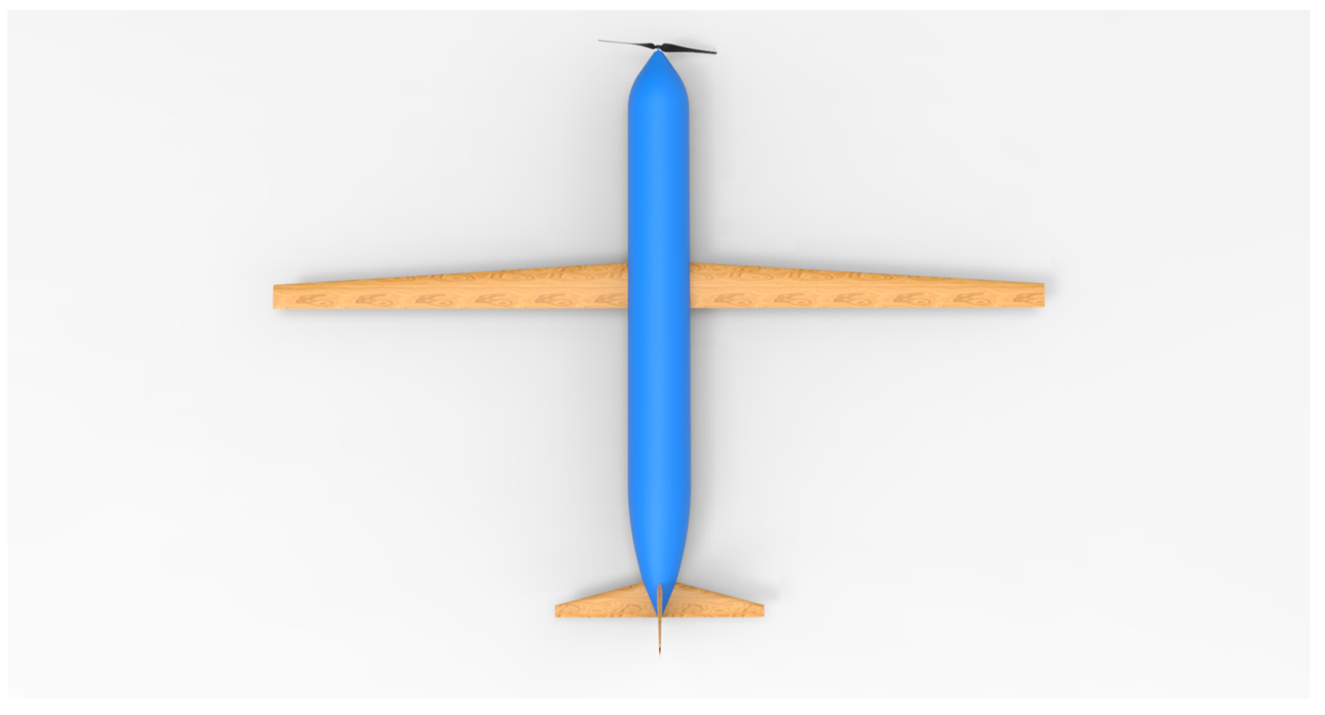
2. Proposed Design of UAV and Its Wheel Disc Brake

The design of FWUAVs with disc brakes for long-duration missions is discussed in this work through optimized analytical methodologies. In order to extend the useful life of disc brakes while keeping their performance qualities, the authors of this research advised adopting high-quality composites in favor of more conventional materials. New integrated analytical and computational structural studies are used to estimate stresses due to heat, whilst new transient-based computationally coupled (structural and thermal) computations are used to estimate stresses owing to friction [14,15,16,17]. An FWUAV’s payload weight and overall weight are related by the following Equation (1), which is inspired by the publication [3].
W Pl W O = 0.201
This fixed-wing UAV has a 5 kg payload, being its primary purpose. With the help of the obtained Equation (1), we can determine that the total mass of this fixed-wing UAV is 25 kg.

2.1. Estimation of Wing Surface Area, Wingspan, Chord Length, and Fuselage Length

From the comparative study [3,4,15,17] of suitable UAVs, which is able to perform the same mission, a choice for wing load for this design was selected as W S = 25   kg m 2 .
S W = W O ( W S )
Wing area can be determined using Equation (2) when takeoff weight and wing loading are known. About 1 square meter is used for the wing area. The third equation (relating wing area to wing span and chord length) may be found numerous times in the literature [3,4,15,17] and is generally acknowledged to be true.
S w = b W C W , root
The standard aspect ratio (AR) of the wing is given in Equation (4). In this work, the ARW was chosen as 15 based on historical relationships [3,4,15,17].
AR W = b W 2 S w
With the help of Equations (3) and (4), the relevant historical relationship, the wingspan is estimated, which is 3.873 m. The root chord of the taper wing is equal to, 1 = 3.873 C W ,   root C W , root = 0.2582   m . The length of the fuselage is mentioned in Equation (5) [3,4,15,17].
L UAV = η × b W
where η was taken as 0.8, then, L UAV = 0.8 × 3.873 = 3.0984   m . The fineness ratio’s assignment is very important to design the diameter of a UAV. With more concern, the fineness ratio (FR) of the fuselage was fixed as 10. The major and minor fineness ratios are mentioned in Equations (6) and (7), respectively [3,4,15,17].
FR F , major = L UAV D f
The estimated fuselage diameter of this UAV is 0.30984 m, wherein Equation (6) has been greatly supported. Another D/T-based fineness ratio is important in the construction of UAVs, wherein the value of this fineness ratio generally lies between 8 and 10 [3,4,15,17].
FR F , minor = D f T f
The estimated fuselage thickness of this UAV is 0.015492 m, wherein Equation (7) has been greatly supported. The literature survey [3,4,15,17] showed that λ = 0.5 is more suitable for the provision of low drag with high lift at a positive angle of attack. Therefore, in this work, λ = 0.5 is used [3,4,15,17].
λ W = C W , tip C W , root
Since both the root chord and the wing taper ratio have already been measured, the tip chord of the wing may be found with relative ease. The primary wing has a tip chord measuring 0.1291 m. Because it is intended for this particular fixed-wing UAV to have a high-wing configuration, the wingspan and each of its subordinate design characteristics are required in order to calculate chord at any place along the span. These parameters are as follows [3,4,15,17]:
C W ¯ = 2 3 C W , root 1 +   λ W + λ W 2 1 + λ W
y MAC = b W 6 ( 1 + [ 2 λ W ] ( 1 + λ W ) )
With the help of Equations (9) and (10), the mean aerodynamic chord and its span-wise location are determined. The mean aerodynamic chord is 0.13154 m and its spanwise position is 0.86067 m. Additionally, the other spanwise chord estimations have been estimated with the help of Equation (11) [3,4,15,17].
C W , y C W , root = 1 [ 2 ( 1 λ W ) y b W ]
Λ LE W = tan 1 [ 2 d W b W ]
The sweep angle of the main wing is estimated as 3.8141°, wherein the needful wing positioned data are substituted in Equation (12). Through the help of relevant Equations (1)–(12), the design parameters of the UAV’s main wing were calculated.

2.2. Empennage Design—Horizontal Tail

From the historical data and thus its regression line formation, the relationship between wing area and horizontal tailplane area was formed [4], which is mentioned in Equation (13).
S H Tail = 0.1737 S w + 0.0366
The planform area of the horizontal tail was attained as S H Tail = 0.1737 1 + 0.0366 = 0.2103   m 2 and the horizontal tail volume was assumed as V H Tail = 0.60 and the aspect ratio of the horizontal tail was picked as 5 [4,8].
AR H Tail = b H Tail 2 S H Tail
S H Tail = b H Tail C H Tail
The tail span and chord root of the horizontal tail are determined as 0.2051 m and 1.02543 m respectively with the support of Equations (14) and (15). Aside from the aforesaid assumptions, this completed literature survey [3,15] provided the info about the tail taper ratio. For this kind of application, a good taper ratio is 0.3, so λ H Tail = 0.3 has been used for the complete tail design.
λ H Tail = C H Tail tip C H Tail root
C H Tail ¯ = 2 3 C H Tail root ( 1 +   λ H Tail + λ H Tail 2 1 + λ H Tail )
y MAC = b   6 ( 1 + 2 λ H Tail 1 + λ H Tail )
Λ LE H Tail = tan 1 [ 2 d H Tail b H Tail ]
With the help of relevant Equations (16)–(19), the design parameters of the UAV’s horizontal tail such as tip chord as 0.06153 m, mean aerodynamic chord as 0.146377819 m, and its spanwise location as 0.210345 m, and finally, the sweep angle as 15.64225° were calculated [3,4,15,17].

2.3. Empennage Design—Vertical Tail

From the historical data and thus its regression line formation, the relationship between maximum takeoff weight and vertical tailplane area was formed [4], and through the standard formulae (Equations (20) to (24)), other parameters developed. From the literature survey [3], the aspect ratio for the vertical tail was picked as AR V Tail = 3 and the taper ratio was obtained as   λ V Tail = 0.3 . The volume of the vertical tail was assumed as V V Tail = 0.07 .
S V Tail = 0.0006 ( W O [ kg ] ) + 0.1475
V V Tail = ( V Tail ) ( S V Tail ) ( b w ) ( S w )
V Tail = 2 S w ( ( V H Tail ) ( C W ¯ ) + ( V V Tail ) ( b W ) ) π   ( R 1 + R 2 )
AR V Tail = ( b V Tail ) 2 S V Tail = b V Tail C V Tail ,   root
λ V Tail = C V Tail ,   tip C V Tail ,   root
With the help of relevant Equations (15)–(19), the design parameters of the UAV’s vertical tail were calculated. The important design parameters are: planform area as 0.1625   m 2 , and thus S V Tail S W = 0.1625 , the tail span as 0.70 m, the root chord as 0.234 m, the tip chord as 0.0702 m, mean aerodynamic chord as 0.2653326 m, and so l V Tail = 1.67   m , the outer and inner radiuses are 0.15492 m and 0.075 m, respectively [3,4,15,17].

2.4. Estimation of Propulsive System and Its Weight

A co-axial propeller system was implemented in this work. The thrust requirement by the single propeller in the co-axial propulsive system was calculated through Equation (25), wherein the forward velocity is assumed as 100 km/h [16].
0.5 ρ A [ ( V e ) 2 ( V o ) 2 ] = W O 2
The thrust requirement of this propulsive system is estimated as 122.625 N and the diameter ( d propeller ) of the single propeller is found out as 25.47 inches.

2.4.1. Estimation of Co-Efficient of Lift (CL)

Technically, the CL has been calculated at the maneuvering of steady level flight because this stage creates the environment, which enforces all the parts of UAVs have been working in good conditions. At steady level flight, the force equilibriums are Lift = Weight and Thrust = Drag; Thus, the force equilibrium equation is revealed in (26) [3,4,15,16,17].
T = V Forward 2 2   ρ C L A P
Finally, the maximum coefficient of lift is calculated as 0.9744, wherein the UAV is assumed to move with maximum forward speed.

2.4.2. Estimation of Power, Propeller’s Pitch and its RPM

Equation (27) contains the relationship of maximum mechanical power required by this propulsive system [3,4,15,16,17].
P Required = TV Forward 2 [ ( T AV Forward 2   ( ρ 2 ) + 1 ) 1 2 + 1 ]
The maximum mechanical power required by this propulsive system is calculated as 3686.62 Watts. The P/D ratio applicable for this above equation is up to 0.1 to 0.6. Therefore, in this work, the P/D ratio was fixed as 0.6, which is mathematically given in Equation (28) [3,4,15,16,17].
p propeller d propeller = 0.6
P Required = k   R 3 D 4 p propeller
The estimated power required and Equations (28) and (29) are supported a lot for the development of other design parameters such as pitch and rotational speeds. The pitch of the propeller is calculated as 15.282 inches and the maximum rotational speed is determined as 4765 RPM.

2.4.3. Estimation of Pitch angle and Chord of the Propeller

The pitch angles and their corresponding chord lengths of the imposed propellers are uniquely developed with the help of Equations (30) and (31). For this work, the numbers of blades are assumed as 2 due to the imposition of the co-axial propulsive system [3,4,15,16,17].
θ Pitch =   arctangent   ( p propeller 2 π r propeller )
C cp = 8 π ( sin ( θ ) ( tan ( θ ) 1 1.2 tan ( θ ) ) ( 1 + 1 1.2 tan ( θ ) ) ) r propeller nC L
With the help of relevant Equations (26)–(31), the design parameters of the UAV’s propeller were found, which are listed in Table 1.

2.5. Aerofoil Selection

The fundamental part of the propeller is aerofoil, which has been shortlisted with utmost care. In this work, the predominant selection factor involved in aerofoil selection is low coefficient drag under the maximum coefficient of lift at the average angle of attack. With this consideration, the best aerofoil was picked as NACA 2412, which was created a low coefficient of drag value than the other best aerofoils that are listed in Table 2 [3,4,15,16,17].

2.6. Weight Estimation

In the weight estimation, the conventional formula has been investigated, wherein the density of the lightweight materials and volume of the components are played the predominant roles. The volume of the propeller is 0.00007605 m3, and the weight of the GFRP propeller is equal to 1646 × 0.00007605 = 0.1251783 kg. The volume of the fuselage is 0.041 m3 thus weight of the UAV’s fuselage is equal to 0.041 × 250 (sandwich composite) = 10.25 kg. The volume of the horizontal tail is estimated as 0.0006144 m3, and thus the weight of the UAV’s horizontal tail is obtained as 0.0006144 × 300 = 0.18432 kg. The volume of the main wing is 0.003 m3, and thereby weight of the UAV’s main wing is equal to 0.003 × 300 = 0.9 kg. The volume of the vertical tail is obtained as 0.0004836 m3, and thus the weight of the UAV’s vertical tail is equal to 0.0004836 × 300 = 0.14508 kg [3,4,15,16,17].

Estimation of Electrical and Electronics System and Its Weight

The maximum power requirement by the unmanned aircraft system is 3686.62 Watts, and the proportional RPM is calculated as 4765. In addition to these parameters, the estimated diameter of the propeller is also included in the selection of the motor. Finally, the motor is shortlisted for this operation. The motor of this work is KWTBLDC-6010-12S, which has a constant velocity rate of 280, and the weight of the motor is 232 g [3,4,15,17].
V Required = RPM Working KV rate
The maximum voltage requirement is obtained as 35 V with the help of Equation (32) and that will help to obtain the battery’s maximum cell requirement [3,4,15,17].
S Required = V Required Maximum V Cell
The number cell requirement is determined as 10 through the guidance of standard Equation (33) and this outcome helped to pick the 10 S LiPo battery, in which the specifications are: overall capacity is 10,000 mAh, the discharge rate is 35C, and the overall weight is 2240 g [3,4,15,17].
V Draw   rate Maximum = P Required V Required Maximum
Through the above-mentioned Equation (34), the maximum current draw rate is calculated as 105.332 A. Based on this estimation, the electronic speed controller (ESC) is finalized with the inclusion of a battery eliminator circuit, and thus, the total weight of the ESC is 79 g. Similarly, all the weights of the components are estimated, which are listed in Table 3.
At last, a brand-new FWUAV is created by employing the aforementioned optimized analytical formulas and derived historical correlations. The proposed UAV is intended for use in highly advanced settings, such as the transport of medical supplies, instruments, weapons, etc. Multiple views of the proposed UAV are pictured in Figure 2 and Figure 3. Given the importance of the key applications, the lifetime of the proposed UAV is a major consideration. It was determined that frictional damage had a much greater impact on the UAV’s components than any other damaging element, and the primary failure reasons were assessed accordingly. Therefore, the frictional force, shear stress calculations, and displacement assessments of an FWUAV’s main wheel disc brake are the primary foci of this work. As shown in Figure 4, a unique disc brake has been constructed using standard analytical formulas and well-documented historical relationships [3,4,15,17].

2.7. Estimation of Stick of Landing Gear and Its Weight (Assymetrical Component)

The focus of this section is to find the design parameters of the UAV’s disc brake through the help of the design data of the landing stick of this proposed UAV. Thus, the estimation of design data and the weight of the UAV’s landing gear is an unavoidable one. Under the design process, the determination of height, mass, volume, and hollow section-based inner and outer diameters of the landing stick are executed. One of the major factors involved in the design process is the fineness ratio (FR), which mostly lies between 5 and 10 [5].
FR major = L UAV H L . S
With the help of Equation (35), the height of the landing stick is determined as 0.30984 m. Another “H/D” based minor FR is vital in the construction of UAV, which deals relationship between the height and diameter of the landing stick [5]. For this work, the value of 5 is used as minor FR and thereby the hollow section based inner and outer diameters of the landing stick are calculated [5].
FR minor = H L . S D L . S
Through Equation (36), the different radiuses of this UAV are determined. The values are: the outer diameter of the LS is 0.061968 m and the inner diameter of the LS is 0.0123936 m [5].
V LG =   π H L . S ( ( r o ) 2 ( r i ) 2 )
The volume of per landing stick is calculated as 0.0036 m3. In addition, the overall weights of the landing sticks are calculated as: 3 × 300 × 0.00092160792576 = 0.829447133184 kg. After the estimation of design data of the landing stick, the predominant focus of this section is to be performed, which is the design process of the wheel and its disc brake [5].
W Wheel = [ W LG ] [ W LSs ] n W
From Table 3 and Equation (38), the weight of the wheel is calculated as 1638.325 g or 3.612 lbs [5].
D Disc =   A ( W wheel ) B or   w Disc =   A ( W wheel ) B
For general aviation the design parameters [5] for Wheel’s width, A = 0.7150, B = 0.312. Rotating   Disc   width   ( in . ) = 0.7150 × ( 3.612 ) 0.312 1.07   inches ; For general aviation, the design parameters [5] for the wheel’s diameter, A = 1.51, B = 0.349. Rotating   Disc   diameter   ( in . ) = 1.51 × ( 3.612 ) 0.349 2.364   inches ;   Various types of tires are involved in constructing an aircraft’s landing gear; however, in this work, three parts are used because the model is a perfect fit for advanced airplanes. In a three-part type tire, the following relationships (Equations (40) to (44)) are obtained [5], which are predominantly used in the calculation of each and every part of the disc brake of fixed wing UAV [5].
AR W = H W W W
D W W W = 2.57895  
W W D W = 0.387755  
d W W W = 20 19
W W d W = 19 20

2.8. Conceptual Design UAV’s Disc Brake (Assymetrical Component)

Analytical calculations are first made for the UAV’s disc brake’s diameter, width, and height. Second, advanced components from earlier research, such as the caliper, smooth pins, and brake pads, are used. CATIA is the best modeling tool for creating the essential conceptual design because a UAV’s disc brakes are made up of multiple intricate components. The recommended modeling approach must therefore be used in the conceptual design of this disc brake.

3. Proposed Methodology and Its Validations

In this research, finite-element-based computational transient structural and thermal assessments are used. Due to the intricacy of the underlying activities, the proposed transient structural and thermal investigations must incorporate susceptibility tests to achieve exceptionally precise results. Researchers apply grid convergence tests and frictional force tests, which rely on experimental validation as sensitivities, to examine the work.

3.1. Computational Model (Symmetrical Study)

The computational model used in the POD experiment is the basis for all the accuracy and reliability evaluations. All of the computational models are based on the ASTM G99 standards. After discovering that the disc brake arrangement of UAVs is graphically comparable to the POD setup, the authors determined to enforce POD-based validations for implemented transient structural simulations. Insight into the typical platform layout of this massive dataset can be gleaned from a survey of the relevant literature [1,14,15,16,17,18,19,20].

3.2. Boundary Conditions and Description about Analyses

Most frictional-based studies use low wear rate, low frictional force, low coefficient of friction, low cost, better mechanical properties, high resistance to frictional loads, good wear resistance, low coefficient of thermal expansion, excellent material availability, good machinability, high melting point, and anti-corrosion as selection criteria. This lightweight material selection for the UAV’s disc brake is dominated by these characteristics, with the inclusion of pertinent requirements from the aforementioned list, such as low frictional stress, high rigidity, and less thermal stress. Because this work ended with POD-based validation, the disc and POD components are critical inputs for the development of this computational model. In which the ‘rosette’ facility was primarily used to determine fiber direction. Another facility known as “oriented set-up” was used to determine the orientation of the laminate of the composites. Finally, the created solid model was used to precisely combine the allocated reinforcements with the matrix. Figure 5 shows a consolidated model of the pin-on-disc test specimen created with the ANSYS Composite Preprocessor tool. The tiny red solid on top was called a pin, and the blue-grey solid on the bottom was called a disc [1,14,21,22,23,24,25,26,27,28,29,30].
In the FEA mathematical modeling of boundary value problems, boundary conditions and governing equations play a key role. This study incorporated four key boundary conditions, including downward force, remote displacement, constant support, and rotational velocities. From the POD test procedures, it is determined that a downward force has been applied to the top of the pin, so a 2 kg weight has been added. The cylindrical surface of the pin is held rigidly, so a fixed support was provided at that face. The disc is modeled to rotate in the direction of the “Z” axis, so a remote displacement is applied in that direction. As “3D” structural elements are used to create the grid, each element must be solved using a stiffness-based dynamic approach and 15 governing equations [14,31,32,33,34,35,36,37,38,39,40,41].

3.3. Validation—I—Grid Convergence Study

The initial step in the validation process for the MMC based on aluminum alloy is to perform a grid convergence test. The presence of the pin slightly modified the mesh formation on the disc’s surface, but otherwise, the test specimen is totally discretized with fine structural elements. To perform this rotodynamic frictional computation, a total of six unique mesh instances are constructed and mandated. Several mesh facilities, such as fine at proximity places, fine at curvature regions, inflations between the pin and disc, face mesh setup at the base of the pin, face mesh setup at the top of the disc, and inflation across the board, are used for this initial grid convergence test. Case III of the mesh performed best in terms of accuracy of the findings and quick computation times, as shown in the full statistical report on the mesh in Table 4, as well as in the full results displayed in Figure 6. Additionally, a second grid convergence test is intended to pick the most reliable sum components. Figure 7 displays the results of the second grid convergence test. This second experiment determined the optimum amount of components, which were then merged with the findings of the first experiment to form the consolidated elements, which are now required for all further calculations [24,25].

3.4. Validation—II—Pin on Disc Based Validation

Second, an aluminum-related MMC is subjected to a POD-based experimental test, with the frictional force recorded and compared to the findings of a computational transient structural analysis. This composite consists of a metal (aluminum 6063) and a matrix (epoxy resin). Production was accomplished using a stir casting technique, with speeds ranging from 250 to 400 RPM and temperatures reaching 600 °C.

3.4.1. Finite Element Analysis Results

The POD-based computational test specimen is next subjected to the FEA results for the aforementioned initial conditions. The precise input conditions used in this in-depth study are a disc rotating at 400 RPM, a weight of 2 kg on the pin, and a fixed support on the pin’s cylindrical surface. The disc used in the frictional test has a diameter of 165 mm and a thickness of 10 mm [26,27,28,29]. The pin used in the experiment has a diameter of 10 mm and a height of 30 mm, as shown in Figure 5. The curvature-based fine mesh approach, shown in Figure 8 and Figure 9, is developed as a direct result of the curvature-based nature of the design of this entire system. Figure 10 and Figure 11 show the pin and disc’s overall deformations and variations in shear stress. There was typically just a need for a single modeling tool for the 2D geometric while getting a composite ready.
Figure 10 and Figure 11 allow us to make the following conclusions: (1) both the pin and the disc undergo linear deformation; (2) the greatest deformation occurs at the disc’s outer region; and (3) the greatest frictional stress is created by the pin apparatus [30,31,32,33,34,35,36]. These findings are consistent with the overall phenomenon. As a result, the results from the FEA simulations are found to be generally accurate. The experimental test is then performed utilizing the aforementioned POD equipment, and the resulting frictional data are recorded once the initial verification is completed.

3.4.2. Experimental Results

All of the equipment and prepared samples for testing are depicted in Figure 12. Figure 12a exhibits MMC based on Al-6063 alloy test samples, and Figure 12b illustrates test configurations. The bundled software, Winducom 2010, and a TR-20LE-PTM-based model with 1–200 kg of operating load and 200–2000 RPM of rotational speed are used for these validation testing. Information on frictional forces has been collated in Table 5, and the error percentage is below 10%, which is acceptable and also suggests that the computational techniques of transient structural analysis have been verified. Computing methods developed for disc brakes and POD setups are directly transferable to the disc brake of UAVs.

3.5. Validation—III—Pin on Disc Based Validation

Thirdly, the validation research is conducted in the same POD test configuration, but with various materials and under varied operating conditions. In this third scenario, Steel EN24 serves as the lightweight material requirement, and typical alloy production practices are used to manufacture test specimens. Working RPM is set to 600, and all other boundary conditions are applied in the same manner as in the second validation example. The test specimen made of Steel EN24 and the resulting frictional forces [N] are shown in Figure 13. The Steel EN24 computational model is used to determine the stresses, deformations, and frictional forces in the transient FEA study. Figure 14 displays the FEA result for Steel EN24, while Table 6 displays the computational findings with the experimental result.
Table 6 indicates that when alloys are investigated using computational techniques, the error percentage between experimental and computational results is smaller and is within accepted ranges [33,34,35,36,37,38,39,40,41]. This means that the proposed methodology can yield results that are applicable to alloys.

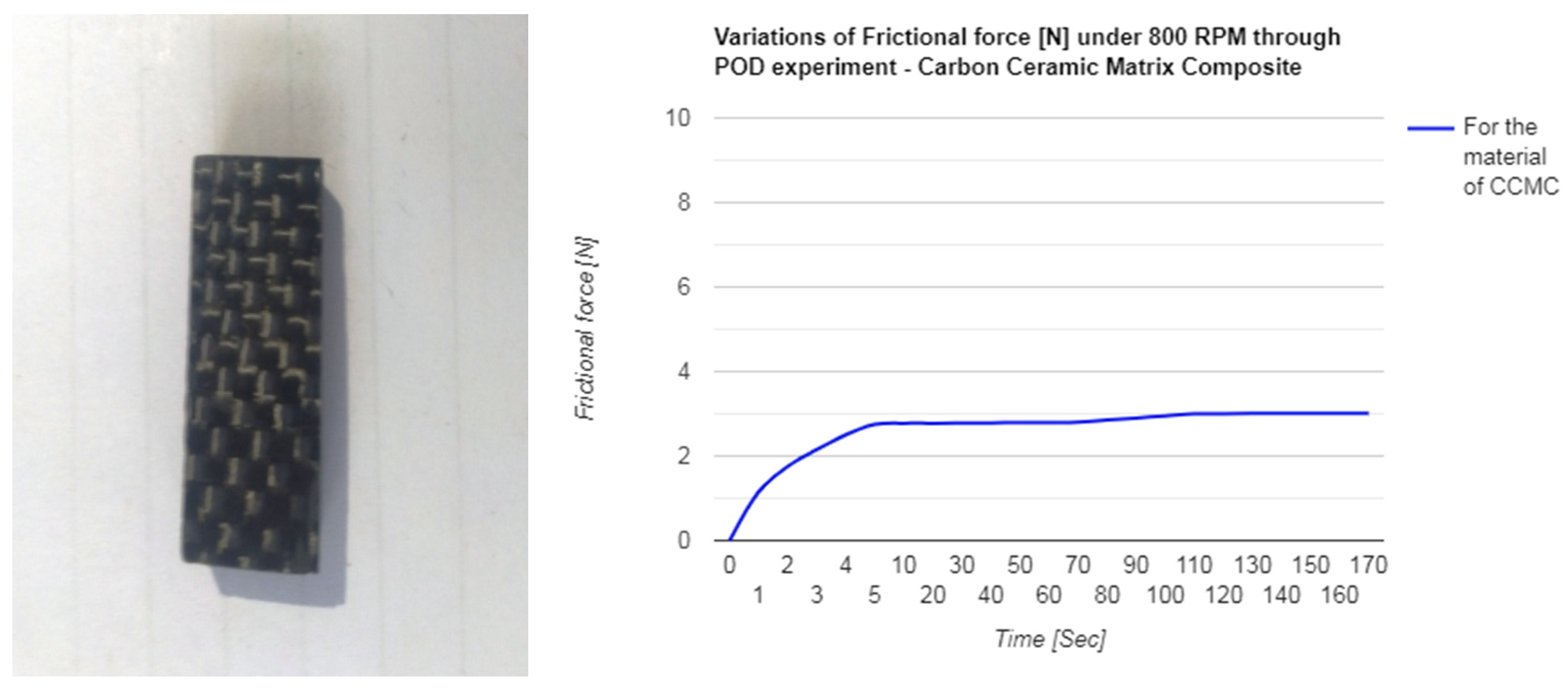
3.6. Validation—IV—Pin on Disc Based Validation

As a fourth phase of validation, the POD experiment is also used to validate the carbon ceramic matrix composite (CCMC), the imposed lightweight material. For CCMC advancements, woven wet carbon fiber with a tensile strength of 230 GPa made up 95% of the contents, while standard SiC made up the remaining 5%. An epoxy resin compression molding machine is used to develop and integrate the various components. The composite’s rotational velocity is the only distinguishing feature. In this case, 800 RPM is the only value given for the working RPM. Test specimen and frictional force [N] results based on CCMC are shown in Figure 15. Stresses, deformations, and frictional forces are all measured and recorded during the transient FEA study that is also performed on the same CCMC computational model. The CMC FEA result is shown in Figure 16, and both the numerical output and the experimental result are shown in Table 7. Table 7 suggests that the proportion of error between experimental and computational results for evaluating rare materials such as CCMC is within a reliable range. As a result, both CCMC and PMC stand to benefit from the proposed approach.

4. Results and Discussions on UAV’S Disc Brake

4.1. Conceptual Design (Asymmterical Case Study)

The UAV disc brake is modeled in CATIA using accepted engineering methods. This design implementation deliberately mandated the use of a complex modeling tool due to the frequent occurrence of compositions of complex components in disc brakes. Illustrations of a UAV’s disc brake are shown in Figure 17.

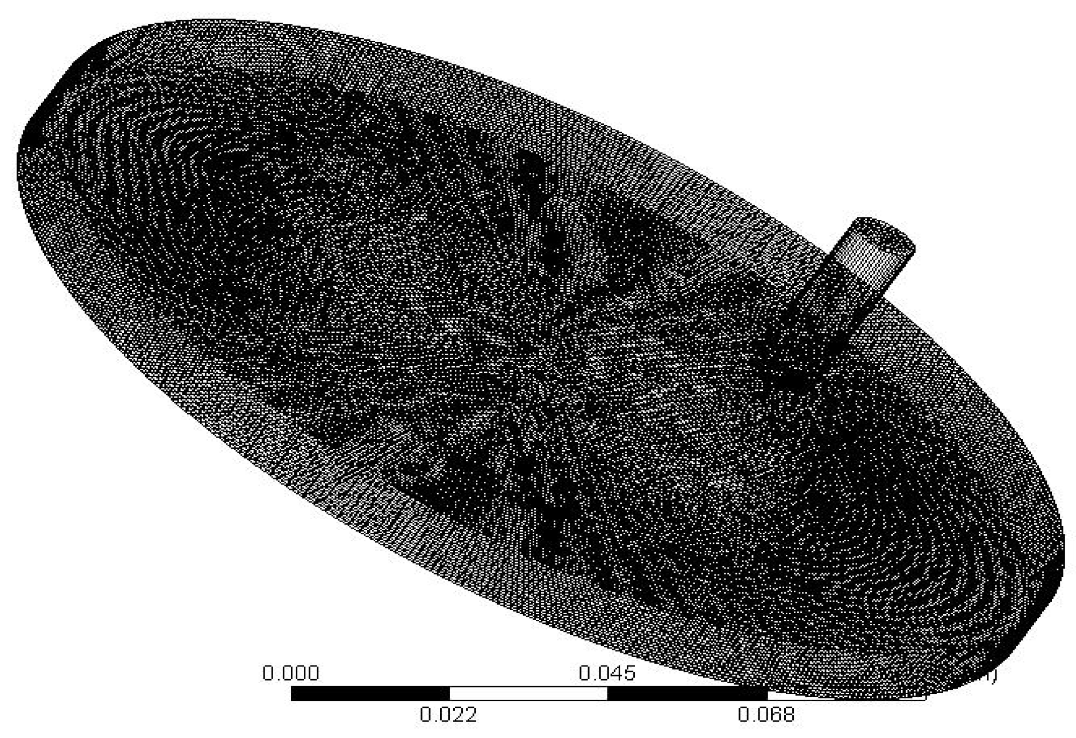
4.2. Discretization and Its Convergence Test

The discretization phase has been studied more thoroughly for disc brakes because of the prevalence of curvature-oriented shapes in this application. Due to this, the authors have opted to use a hybrid discretization approach that employs both structural and unstructural grid elements. Disc brakes with a hybrid grid structure are depicted in Figure 18. The disc’s rotation requires special care because it is continually making contact with the braking pads. In order to adequately capture all the subcomponents, which are typically discs in motion, an unstructured mesh is put on the disc. On the other hand, the structural mesh may be simply created for brake pads because they do not contain any moving parts. A hybrid mesh is one that contains both structural and unstructural nodes. In order to depict this hybrid mesh, we combine cuboids and tetrahedral elements in a multi-zone-based local mesh configuration. As grid amalgam increases the likelihood of oscillation during convergence, the grid convergence test is an essential prerequisite. After two other tests are finished, the time came to test the grid convergence of the UAV disc brakes. The second sensitivity test optimization focused on the grid and its sections. Analysis of convergence is carried out by modeling the disc brake of a KFRP-based UAV on six different grids. The results of the second grid convergence test are summarized statistically in Table 8. Both the standard mesh facility and the integrated gird facility are used in this second sensitivity test. The entire frictional loads imposed on the UAV disc brake during this grid independence test are shown in Figure 19. At this point, we know that the fine mesh facility can be relied upon. These sensitivity evaluations demonstrate the high reliability of the results obtained using the computational approaches developed for this study.
The authors must undergo validation just to guarantee the integrity of the computational procedures used by the tools. Thus, for the same RPMs, both computational tests and experimental tests are compiled and compared. It follows that the necessary computing procedures have been validated and confirmed, and they may generate trustworthy results, as they obtained error percentages are well within the acceptable range. This means that even the most time-sensitive real-world applications still need to use the same time-tested computational procedures.

4.3. Boundary Conditions

Boundary conditions, such as remote displacement, rotational velocities, and supports, are enforced in this real-time example with the precision and testing that is necessary to ensure valid results [1,14].
V Forward [ km / h ] = D Wheel [ cm ] RPM 0.001885  
Forward speed was assumed as 25 m/s, and the diameter of the main wheel was calculated as 15 cm, therefore, RPM = 90 0.001885 15 = 90 0.028275 = 3183 . The UAV’s disc brake might be subjected to an external rotational stress of the same magnitude according to the analytical Equation (45) found in the section Landing/Take-off maneuvers. [RPM = 3183]. An off-board displacement facility locked the UAV’s disc in place, while a fixed support held the disc pad in position. The flexing quality is also imparted to the rotating disc part so that it could be used in real-world applications. As an added bonus, frictional contact has been established between the disc pad and the revolving disc, with the frictional coefficients modified in accordance with the composites. The one-way connection feature is used to link the composite specimen tool to the FEA preprocessor as well as solver tool. The complicated composite specimens are successfully transferred from the experimental production stage to the solver using this state-of-the-art computational simulation technology.

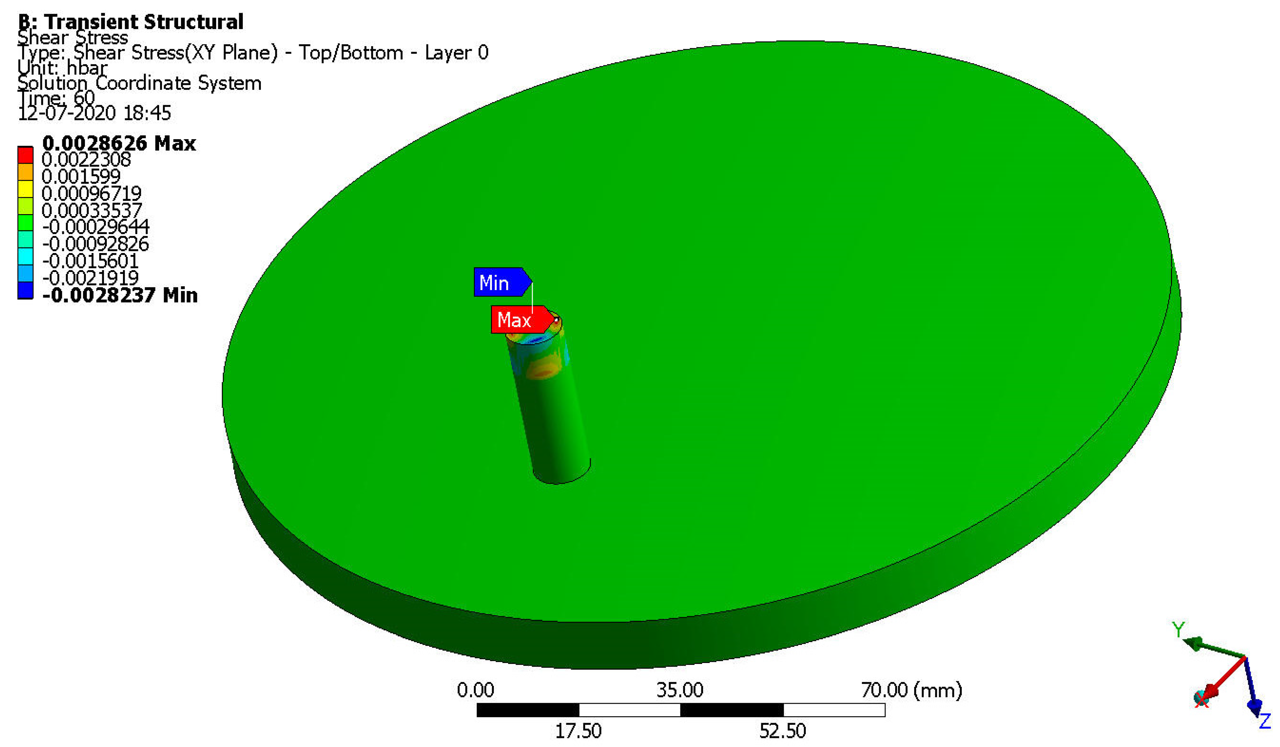
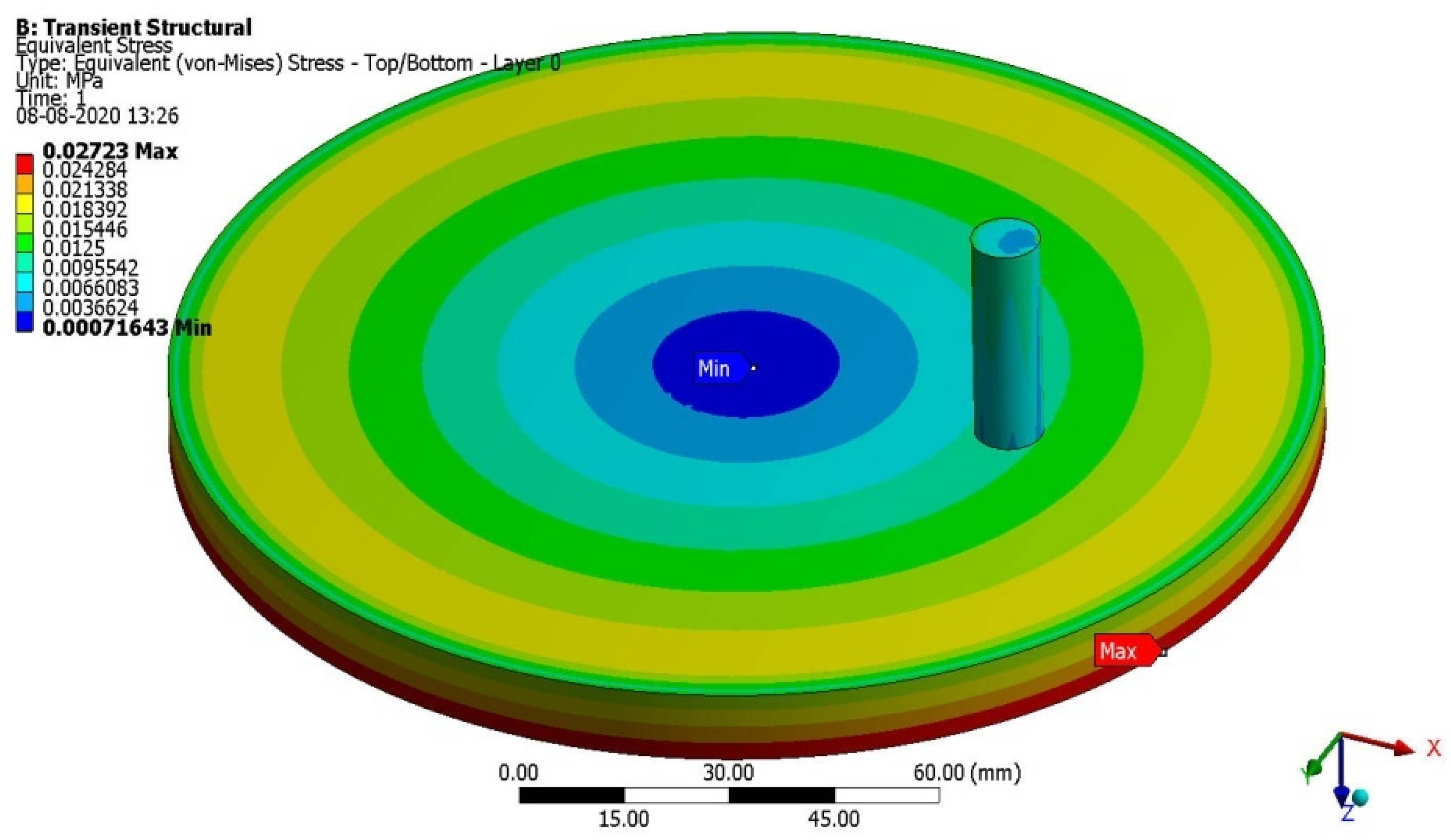
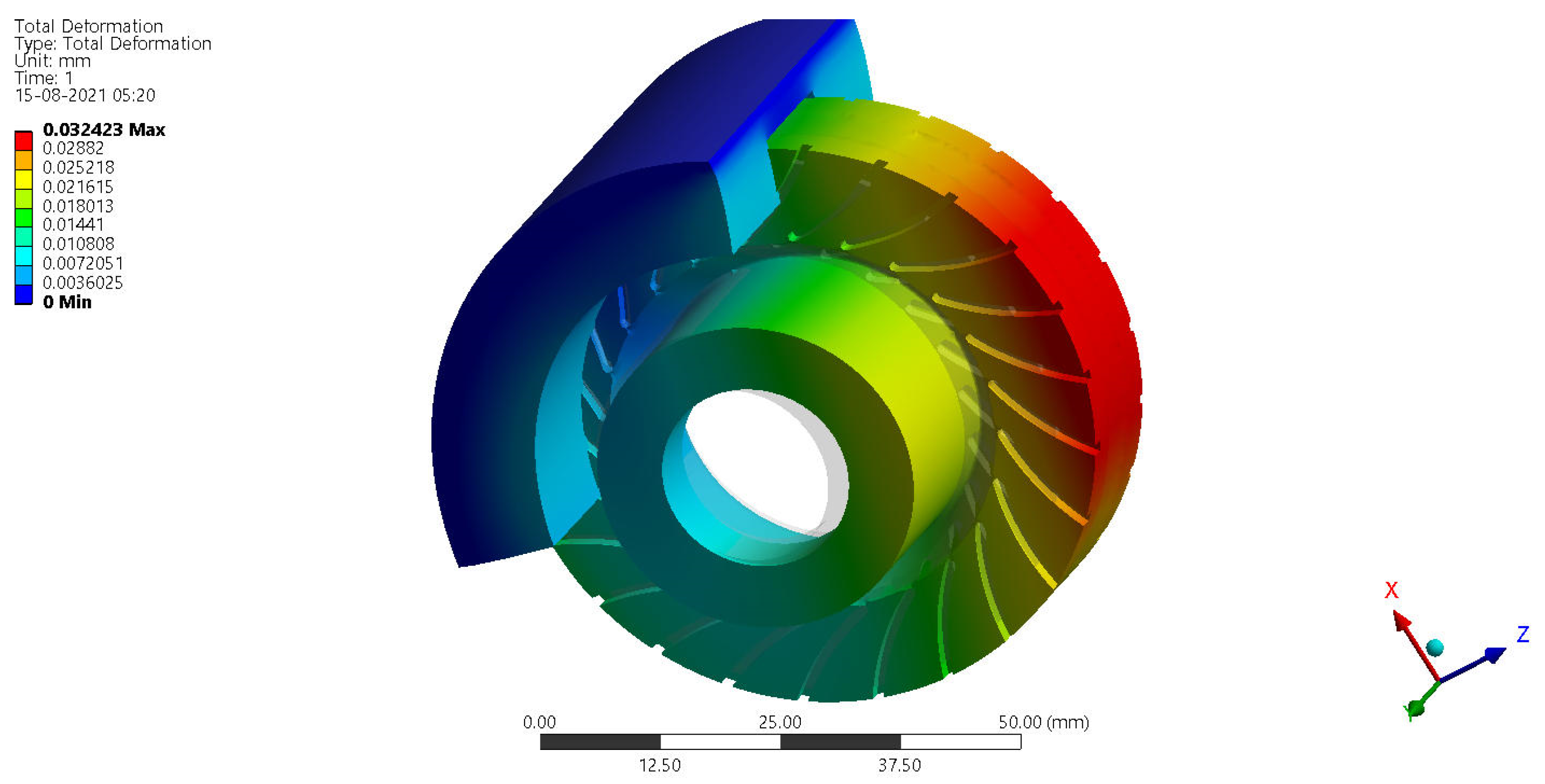
4.4. Structural Results—Assymetrical Failure Factors

Through the use of frictional and structural calculations, the primary and highest performing materials are selected for the UAV’s disc brake, ensuring the vehicle’s stopping power is maximized. Kevlar fiber outperforms epoxy resin under rotodynamic frictional loads, as shown by both preliminary and standard tests. The disc brake computational calculations of this UAV take into account the performance of various high-quality materials, such as carbon fiber and E-Glass fiber. Finally, considering the disc brake’s operational characteristics, CCMC, a thermal load-resisting material, is accounted for. Computational model processing of CCMCs included the incorporation of carbon fiber as reinforcement, with the primary goal of increasing toughness; epoxy resin as adhesive, with the primary goal of maintaining the reinforcing phase in the desired orientation, acting as a load transfer media, and shielding the reinforcement from the environment; and silicon carbide as filler material, in the form of particle-sized spherical spheres, to the matrix materials. For this reason, we have narrowed down the top choices for this computation to include CFRP-UD-Prepreg based PMC, CFRP-Woven-Wet based PMC, E-Glass-Woven based PMC, KFRP-UD-49-Epoxy based PMC, and CCMC. The formation of frictional forces and, by extension, the various stresses, may be computed with the help of these boundary conditions. Figure 20, Figure 21, Figure 22 and Figure 23 show the outcomes of deformations and different stresses on high-quality materials. Stress hotspots caused by deformation are shown in Figure 23 and Figure 24, and those caused by stress are shown in Figure 20, Figure 21 and Figure 22. Figure 20 demonstrates that disc deformation is the most extreme. Based on the illustrations in Figure 21, Figure 22 and Figure 23, we can conclude that the inner hub and the inside of the disc are subjected to the most pressure. These locations pose serious threats to one’s health and happiness and should be avoided at all costs if one seeks to live a long and fruitful life. Figure 25 and Figure 26 are display the comprehensive outcomes of the UAV’s disc braking testing.
Based on Figure 24, Figure 25 and Figure 26, the following recommendations are made: Unidirectional prepreg categorized Kevlar fiber reinforced with epoxy resin-based PMC induced very few frictional stresses compared to all other lightweight materials; and carbon fiber reinforced ceramic matrix based advanced composite reacted less structural deformations and equivalent elastic moduli compared to other CFRP materials.

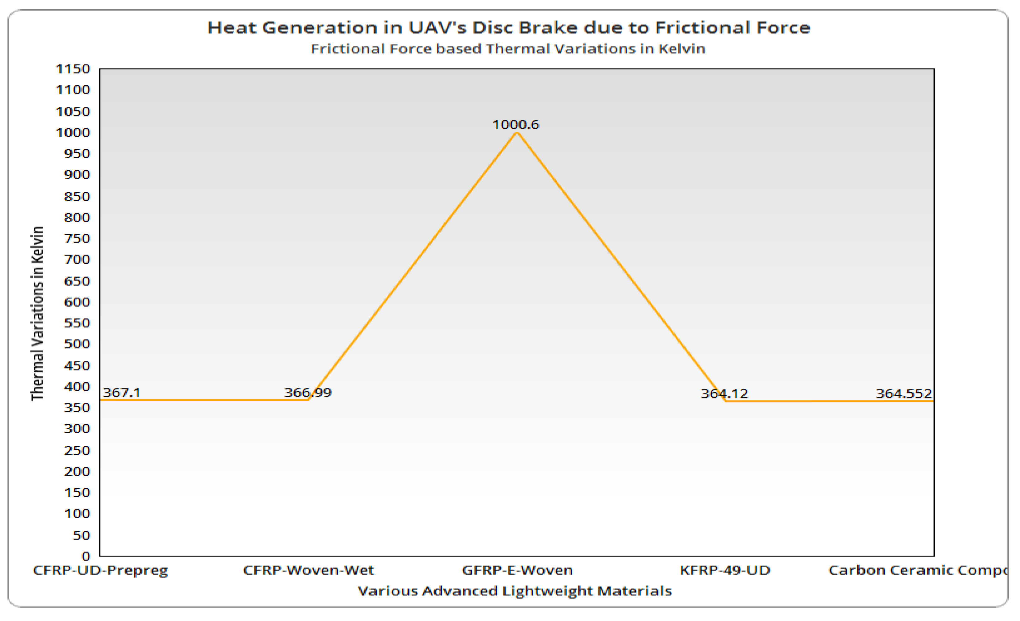
4.5. Thermal Stress Results—Assymetrical Failure Factors

The disc brake on the UAV has survived for the most part due to the effort put into generating thermal stress and estimating it. Using verified structural outputs, this work computationally analyses the thermal generation and its impacts on the UAV’s disc brake. The ANSYS transient thermal tool is the computational platform integral to achieving thermal outcomes such as heat production owing to friction and, by extension, thermal stress induction. Computational evaluations rely heavily on material parameters including thermal conductivity, thermal coefficient, and thermal diffusivity; to obtain these values, researchers have combed through the literature [2,6,7,8,9,10,11,12,13]. UAV disc brake heat production [Q] is equal to,
Q =   σ Induced Normal μ F V Relative
Δ T =   T 0 + [ [ φ q k ] 4 α t Frictional   Interaction 7 22 ]
The heat generation due to friction was evaluated and compared in Figure 26 using the analytical approach (Equations (46) and (47)) and computational structural outcomes.
Figure 27 shows that the PMC and CCMC made from KFRP-49-UD reacted with far less heat generation than the other two outstanding materials. It was also evidently recognized that the free stream flow velocity based on UAV movement and the resulting normal stress at the region of friction were key inputs for the estimate of heat generation. Several of the most effective lightweight materials were subjected to thermal stresses at the calculated temperature; the combined impacts of these boundary conditions are depicted in Figure 28. Distant displacement inside the rotating disc, fixed support outside the brake pad, and an approximated temperature inside the brake pad were the boundary conditions for this thermal experiment. Figure 29 and Figure 30 show the outcomes of thermal tests performed on the UAV’s disc brake to narrow down the list of increased lightweight materials. All the best materials were compared in the final analysis. KFRP-49 and CFRP-Woven are both unidirectional. Because of the reduced thermal stress experienced during production, wet-based polymer matrix composites are superior to competing high-quality goods. Figure 31 displays the full outcomes of thermal stress.

5. Conclusions

The widespread usage of UAVs has led to the development of multidisciplinary research on the subject in recent years. As a result of this new development, the FWUAV is chosen to serve as the platform for this endeavor. The spinning disc is the most susceptible to failure in the FWUAV, which is why the target of this domain is on the disc brake and the material optimization of the UAV, which is focused on low frictional stress and thermal stress generators. The estimations of the whole FWUAV included both conventional and standard theoretical calculations. The design of the UAV’s spinning disc played a significant part in these estimations. When it came to the creation process of the revolving disc for the UAV, CATIA was the modeling tool that successfully created the disc brake. Computational platforms such as ANSYS ACP, ANSYS Transient Structural, and ANSYS Transient Thermal are utilized extensively in the process of optimizing the material in question.
Finally, when subjected to structural loadings, the GFRP-E-Woven-Epoxy, KFRP-UD-49-Epoxy-based polymer matrix composites, and KFRP-UD-49-Honeycomb-based sandwich structured composite performed better than the others. In comparison to other premium PMCs, the GFRP-E-Woven-Epoxy-based PMC is reacted and reduced the frictional stress level froma minimum of 18.26 percent to a maximum of 42.58 percent; the KFRP-UD-49-Epoxy-based PMC is reacted and reduced the frictional stress level at a minimum of 17.18 percent to a maximum of 41.82 percent; in addition, the KFRP- Because of this significant high reduction of structural and frictional outcomes, the Uni-Directional-49-Kevlar Fiber is extended to form advanced composites. Subsequently, it is strongly observed that all of the co-products of KFRP-based advanced composites performed better than other imposed lightweight materials.
In addition, the ceramic composite is included in the material lists that are discussed previously, and as a result, the thermal stress simulations are performed. The KFRP-49-UD-Epoxy-based polymer matrix composite material is reacted 70 percent of lesser thermal outcomes than other superior materials [GFRP-E-Woven-Epoxy]. This is due to the low heat generations that occurred between the rotating disc and the brake pad, as well as the consideration of the low thermal stress induction factor. PMCs based on KFRP-49-UD-Epoxy are chosen and advised for use on real-time FWUAVs because they allow for a maximum forward speed of 3183 RPMs and 25 m per second.
The future planned work is to extend the same investigation toother frictional parts of UAVs. The focused other frictional parts of UAVs are rotor brakes at the gearbox of the rotary wing UAV, brake-shoes of the long-range FWUAVs, and moving parts in the hybrid mechanism of advanced UAVs. Additionally, various lightweight materials such as hybrid composites, polymer fiber-based natural composites, natural resin-based polymer composites, high SiC mixtures loaded CCMCs, and nanocomposites are planned to impose on these aforesaid applications.

Author Contributions

Conceptualization, V.R.; methodology, V.R. and R.K.G.; software, V.R. and P.R.; validation, H.A.Z.A.-b., R.K.G. and R.R.; formal analysis, A.M.A.; investigation, V.R.; resources, R.K.G.; data curation, P.R. and A.M.A.; writing—original draft preparation, V.R., P.R., and H.A.Z.A.-b.; writing—review and editing, A.M.A., and H.A.Z.A.-b.; visualization, M.A.-B.; supervision, P.R. and M.A.-B.; project administration, A.M.A. and M.A.-B.; funding acquisition, P.R. All authors have read and agreed to the published version of the manuscript.

Funding

This research was funded by Universiti Sains Malaysia, Short Term Grant No. 304/PAERO/6315291, and the APC was funded by Universiti Sains Malaysia.

Institutional Review Board Statement

Not applicable.

Informed Consent Statement

Not applicable.

Data Availability Statement

Not applicable.

Acknowledgments

The computational facilities involved in this work are supported by Aircraft Design and Analyses Laboratory, Department Aeronautical Engineering, Kumaraguru College of Technology (KCT), Coimbatore–641049, Tamil Nadu, India. Therefore, the authors of this work would like to express their gratitude to all upper management and specialists.

Conflicts of Interest

The authors declare no conflict of interest.

Symbols and Notations

This investigation is predominantly aimed to construct a unique UAV and its disc brake so the design process has been played a vital role. Hence, the symbols and notations of imposed design parameters of UAV need to be listed in a separate section for the purpose of clarification and accurate calculation. In this regard, Table 1 was formed, which contained all the imposed symbols and its notations.
List of Symbols and Notations.
SymbolMeaning
W Pl Payload Weight for UAV
W O Overall Take-Off Weight of UAV
( W S ) Wing Loading of the UAV
S W Surface area of the Wing
b W Wingspan
C Wing root Root chord of the Wing
L UAV Length of the UAV
D f Diameter of the Fuselage
λ Taper ratio
C Wing tip Tip chord of the Wing
C Wing ¯ Mean Aerodynamic Chord of the Wing
y MAC ‘y’ location of the Mean Aerodynamic Chord
y ‘y’ wise position in Wing
S H Tail Surface Area of the Horizontal Tail
V H Tail Volume Coefficient of the Horizontal Tail
L H Tail Distance between MAC of Hori. Tail to MAC of Wing
b H Tail Horizontal Tail-Span
AR H Tail Aspect Ratio of the Horizontal Tail
R 1 Radius at Wing-Fuselage Interaction
R 2 Radius at Tail region
V o Velocity of the Atmospheric fluid
V e Velocity of the UAV
T Thrust
ρ Density of the Atmospheric fluid
r Radius of the Propeller
C L Coefficient of Lift
A P Disc Area of the Propeller
V Forward Velocity at forward manuvering
θ Pitch angle
C cp Chord of the propeller
r propeller Radius of the propeller
nNumber of blades involved in propeller
kDesign factor [5.3×10⁻¹⁵]
RRotational speed of the rotor in RPM
DDiameter of a rotor in inches
p propeller Pitch of rotor in inches
PRequired power in watts
aChord at wing root
bChord at wing tip
cHalf of the wingspan
H L . S Height of the Landing Stick
r1, r2Inner and Outer radius of the Landing Stick
DWNominal diameter of wheel/disc in inch
WWNominal section Width of wheel/disc in inch
dWNominal Wheel/Rim Diameter in inch

References

  1. Kumar, G.R.; Vijayanandh, R.; Kamaludeen, M.B.; Balasubramanian, S.; Jagadeeshwaran, P.; Ramesh, M. Comparative Structural Characterization of Fiber Reinforced Composite Rotating Disc: A Validated Investigation. Tribol. Ind. 2020, 42, 608–620. [Google Scholar] [CrossRef]
  2. Vashi, Y. Structural and thermal optimization of rotor of multi-disc brake of aircraft. Int. J. Mech. Prod. Eng. 2018, 6, 16–23. [Google Scholar]
  3. Kisabo, A.B.; Osheku, C.A.; Samuel, S.O. Conceptual Design, Analysis and Construction of a Fixed-Wing Unmanned Arial Vehicle for Oil and Gas Pipeline Surveillance. J. Aircr. Spacecr. Technol. 2017, 1, 18–29. [Google Scholar] [CrossRef]
  4. Gómez-Rodríguez, A.; Sanchez-Carmona, A.; García-Hernández, L.; Cuerno-Rejado, C. Preliminary Correlations for Remotely Piloted Aircraft Systems Sizing. Aerospace 2018, 5, 5. [Google Scholar] [CrossRef]
  5. Raymer, D. Aircraft Design A Conceptual Approach, 6th ed.; AIAA: Reston, VA, USA, 2018; ISBN 978-1-62410-490-9. [Google Scholar] [CrossRef]
  6. Wróbel, G.; Pawlak, S.; Muzia, G. Thermal diffusivity measurements of selected fiber reinforced polymer composites using heat pulse method. Arch. Mater. Sci. Eng. 2011, 48, 25–32. [Google Scholar]
  7. Scruggs, A.M.; Kirmse, S.; Hsiao, K.-T. Enhancement of Through-Thickness Thermal Transport in Unidirectional Carbon Fiber Reinforced Plastic Laminates due to the Synergetic Role of Carbon Nanofiber Z-Threads. J. Nanomater. 2019, 2019, 1–13. [Google Scholar] [CrossRef]
  8. Dong, K.; Liu, K.; Zhang, Q.; Gu, B.; Sun, B. Experimental and numerical analyses on the thermal conductive behaviors of carbon fiber/epoxy plain woven composites. Int. J. Heat Mass Transf. 2016, 102, 501–517. [Google Scholar] [CrossRef]
  9. Alarifi, I.M. Investigation the conductivity of carbon fiber composites focusing on measurement techniques under dynamic and static loads. J. Mater. Res. Technol. 2019, 8, 4863–4893. [Google Scholar] [CrossRef]
  10. Takizawa, Y.; Chung, D.D.L. Through-thickness thermal conduction in glass fiber polymer–matrix composites and its enhancement by composite modification. J. Mater. Sci. 2015, 51, 3463–3480. [Google Scholar] [CrossRef]
  11. Brown, I.; Burgoyne, C. The friction and wear of Kevlar 49 sliding against aluminium at low velocity under high contact pressures. Wear 1999, 236, 315–327. [Google Scholar] [CrossRef]
  12. Ventura, G.; Martelli, V. Thermal conductivity of Kevlar 49 between 7 and 290 K. Cryogenics 2009, 49, 735–737. [Google Scholar] [CrossRef]
  13. Zhao, J.; Cai, R.; Ma, Z.; Zhang, K.; Liang, H.; Qiu, H.; Liu, S.; Xie, W. Preparation and properties of C/SiC composites reinforced by high thermal conductivity graphite films. Diam. Relat. Mater. 2021, 116, 108376. [Google Scholar] [CrossRef]
  14. Raja, V.; Gnanasekaran, R.K.; Kaladgi, A.R.; Rajendran, P.; Khan, S.A.; Asif, M. Multi-Disciplinary Computational Investigations on Asymmetrical Failure Factors of Disc Brakes for Various CFRP Materials: A Validated Approach. Symmetry 2022, 14, 1616. [Google Scholar] [CrossRef]
  15. Vijayakumar, M.; Vijayanandh, R.; Ramesh, M.; Senthil Kumar, M.; Raj Kumar, G.; Sivaranjani, S.; Jung, D.W. Conceptual Design and Numerical analysis of an Unmanned Amphibious Vehicle. In Proceedings of the AIAA Scitech 2021 Forum, Reston, VA, USA, 4 January 2021. [Google Scholar]
  16. Yeong, S.P.; Dol, S.S. Aerodynamic Optimization of Micro Aerial. Veh. J. Appl. Fluid Mech. 2016, 9, 2111–2121. [Google Scholar]
  17. Vijayanandh, R.; Senthilkumar, S.; Rajkumar, R.; Kumar, A.; Kumar, J.D.; Kumar, K.K.; Prakash, R.A. Conceptual design and computational investigations of fixed wing unmanned aerial vehicle for medium-range applications. Autonomous Connect. Heavy Veh. Technol. 2022, 353–374. [Google Scholar] [CrossRef]
  18. Ong, W.; Srigrarom, S.; Hesse, H. Design methodology for heavy-lift unmanned aerial vehicles with coaxial rotors. In Proceedings of the AIAA SciTech Forum, San Diego, CA, USA, 7–11 January 2019. [Google Scholar] [CrossRef]
  19. Perdiou, A.S.; Eldin, R.A.; Hajaj, K.R.; Rominu, M.; Sinescu, C.; Negrutiu, M.; Hajaj, T.A. Comparative Evaluation of Stress Resistance Between Nano-hybrid Composite and Ormocer Restorations on Posterior Teeth-in vitro Study. Mater. Plast. 2020, 57, 8–12. [Google Scholar] [CrossRef]
  20. Lei, Y.; Huang, Y.; Wang, H. Aerodynamic Performance of an Octorotor SUAV with Different Rotor Spacing in Hover. Processes 2020, 8, 1364. [Google Scholar] [CrossRef]
  21. Raja, V.; Solaiappan, S.K.; Kumar, L.; Marimuthu, A.; Gnanasekaran, R.K.; Choi, Y. Design and Computational Analyses of Nature Inspired Unmanned Amphibious Vehicle for Deep Sea Mining. Minerals 2022, 12, 342. [Google Scholar] [CrossRef]
  22. Lichota, P. Multi-Axis Inputs for Identification of a Reconfigurable Fixed-Wing UAV. Aerospace 2020, 7, 113. [Google Scholar] [CrossRef]
  23. Venkatesan, K.; Geetha, S.; Vijayanandh, R.; Kumar, G.R.; Jagadeeshwaran, P. Advanced structural analysis of various composite materials with carbon nano-tubes for property enhancement. AIP Conf. Proc. 2020, 2270, 030005. [Google Scholar] [CrossRef]
  24. Chu, T.; Starek, M.; Berryhill, J.; Quiroga, C.; Pashaei, M. Simulation and Characterization of Wind Impacts on sUAS Flight Performance for Crash Scene Reconstruction. Drones 2021, 5, 67. [Google Scholar] [CrossRef]
  25. García-León, R.; Afanador-García, N.; Gómez-Camperos, J. Numerical Study of Heat Transfer and Speed Air Flow on Performance of an Auto-Ventilated Disc Brake. Fluids 2021, 6, 160. [Google Scholar] [CrossRef]
  26. Kumar, G.R.; Vijayanandh, R.; Venkatesan, K.; Ramesh, M.; Kumar, M.S.; Balaji, S. Comparative Investigations onthe Main Elements of Carbon Fiber Based Composites Using Computational Structural Simulations. J. Phys. Conf. Ser. 2020, 1504, 012003. [Google Scholar] [CrossRef]
  27. Venkatesan, K.; Ramanathan, K.; Vijayanandh, R.; Selvaraj, S.; Kumar, G.R.; Kumar, M.S. Comparative structural analysis of advanced multi-layer composite materials. Mater. Today Proc. 2019, 27, 2673–2687. [Google Scholar] [CrossRef]
  28. Mirrudula, P.; Priya, P.K.; Malavika, M.; Kumar, G.R.; Vijayanandh, R.; Kumar, M.S. Comparative structural analysis of the sandwich composite using advanced numerical simulation. AIP Conf. Proc. 2020, 2270, 040005. [Google Scholar] [CrossRef]
  29. Raja, V.; Venkatesan, K.; Ramesh, M.; Kumar, G.R.; Kumar, M.S. Optimization of orientation of carbon fiber reinforced polymer based on structural analysis. Int. J. Sci. Technol. Res. 2019, 8, 3020–3029. [Google Scholar]
  30. Arul, P.R.; Vijayanandh, R.; Ramesh, G.; Hariaran, S.; Janardhanan, Y.; Senthil, K.M.; Jagadeeshwaran, P. Investigation of Automotive Disc Brake′s Material Based on Tribological Parameters by Using Computational Structural Analysis. Tribol. Charact. Surf. Coat. 2022, 10, 211–238. [Google Scholar] [CrossRef]
  31. Vinsiya, A.M.; Janaki, B.R.; Kings, R.M.; Vijayanandh, R.; Prakash, R.A.; Kumar, G.R.; Balasubramanian, S. Comparative structural and frictional analyses on various lightweight materials for aircraft disc brake. Mater. Today Proc. 2022, 59, A22–A35. [Google Scholar] [CrossRef]
  32. León, R.A.G.; Rojas, E.P. Analisis de la cantidad de flujo de calorcircundante entre los canales de refrigeraciónentres discos de frenoautoventilados. Ing. Univ. 2016, 21, 71–96. [Google Scholar] [CrossRef]
  33. Kesavan, K.; Kiran, P.; Sivaguru, M.; Prasanth, S.I.; Sudharsan, R.; Kumar, G.R.; Vijayanandh, R. Multi-objective Structural Analysis of Kevlar Fiber Reinforced Polymer Composite. Recent Adv. Smart Manuf. Mater. 2021, 11, 137–151. [Google Scholar] [CrossRef]
  34. Pisciotta, A.; Di Lorenzo, R.; Novara, A.; Laudicina, V.A.; Barone, E.; Santoro, A.; Gristina, L.; Barbagallo, M.G. Cover crop and pruning residue management to reduce nitrogen mineral fertilization in mediterranean vineyards. Agronomy 2021, 11, 164. [Google Scholar] [CrossRef]
  35. Prasanth, S.I.; Kesavan, K.; Kiran, P.; Sivaguru, M.; Sudharsan, R.; Kumar, G.R.; Vijayanandh, R. Fiber Oriental Optimization on Glass Fiber Reinforced Polymer Composite in Multi Objective Perspective based on Computational Structural Analysis. J. Phys. Conf. Ser. 2021, 1849, 012005. [Google Scholar] [CrossRef]
  36. Sharath, B.; Venkatesh, C.; Afzal, A.; Aslfattahi, N.; Aabid, A.; Baig, M.; Saleh, B. Multi Ceramic Particles Inclusion in the Aluminium Matrix and Wear Characterization through Experimental and Response Surface-Artificial Neural Networks. Materials 2021, 14, 2895. [Google Scholar] [CrossRef] [PubMed]
  37. Rethnam, G.S.N.; Manivel, S.; Sharma, V.K.; Srinivas, C.; Afzal, A.; Razak, R.K.A.; Alamri, S.; Saleel, C.A. Parameter Study on Friction Surfacing of AISI316Ti Stainless Steel over EN8 Carbon Steel and Its Effect on Coating Dimensions and Bond Strength. Materials 2021, 14, 4967. [Google Scholar] [CrossRef] [PubMed]
  38. Prasanth, S.I.; Kesavan, K.; Kiran, P.; Sivaguru, M.; Sudharsan, R.; Vijayanandh, R. Advanced structural analysis on e-glass fiber reinforced with polymer for enhancing the mechanical properties by optimizing the orientation of fiber. AIP Conf. Proc. 2020, 2270, 040006. [Google Scholar] [CrossRef]
  39. Afzal, A.; Mujeebu, M.A. Thermo-Mechanical and Structural Performances of Automobile Disc Brakes: A Review of Numerical and Experimental Studies. Arch. Comput. Methods Eng. 2018, 26, 1489–1513. [Google Scholar] [CrossRef]
  40. Bhagavathiyappan, S.; Balamurugan, M.; Rajamanickam, M.; Vijayanandh, R.; Kumar, G.R.; Kumar, M.S. Comparative computational impact analysis of multi-layer composite materials. AIP Conf. Proc. 2020, 2270, 040007. [Google Scholar] [CrossRef]
  41. Belhocine, A.; Afzal, A. Computational finite element analysis of brake disc rotors employing different materials. Aust. J. Mech. Eng. 2020, 20, 637–650. [Google Scholar] [CrossRef]
Figure 1. The steps taken to implement the suggested hybrid methodology.
Symmetry 14 02035 g001
Figure 2. A typical top view of the proposed FWUAV.
Symmetry 14 02035 g002
Figure 3. Conceptual design of a proposed FWUAV.
Symmetry 14 02035 g003
Figure 4. Complete design details of UAV’s disc brake (asymmetrical component).
Symmetry 14 02035 g004
Figure 5. Computational test set-up with boundary conditions details.
Symmetry 14 02035 g005
Figure 6. Grid convergence test—I.
Symmetry 14 02035 g006
Figure 7. Grid convergence test—II.
Symmetry 14 02035 g007
Figure 8. Solid model-based representation of discretized structure of POD test model [Mesh Case—II].
Symmetry 14 02035 g008
Figure 9. Wireframe model-based representation of fine discretized structure of POD test model [Mesh Case—VI].
Symmetry 14 02035 g009
Figure 10. The variations of total deformation.
Symmetry 14 02035 g010
Figure 11. Frictional stress generations on POD set-up.
Symmetry 14 02035 g011
Figure 12. Machining product and pin-on-disc setup (a) test specimen, (b) POD test set-up.
Symmetry 14 02035 g012
Figure 13. Experimental test specimen and its frictional force [N] outcome of steel based test specimen.
Symmetry 14 02035 g013
Figure 14. Stress variations on the pin-on-disc Steel EN24′s test specimen under 600 RPM.
Symmetry 14 02035 g014
Figure 15. Experimental test specimen and its frictional force [N] outcome of CCMC based test specimen.
Symmetry 14 02035 g015
Figure 16. Stress variations on the pin-on-disc CCMC’s test specimen under 800 RPM.
Symmetry 14 02035 g016
Figure 17. A typical isometric view of UAV’s disc brake.
Symmetry 14 02035 g017
Figure 18. Discretized structure of UAV’s disc brake.
Symmetry 14 02035 g018
Figure 19. Grid convergence test on UAV’s disc brake.
Symmetry 14 02035 g019
Figure 20. Deformed structure of KFRP-UD-49-Epoxy.
Symmetry 14 02035 g020
Figure 21. Shear stress variations of KFRP-UD-49-Epoxy.
Symmetry 14 02035 g021
Figure 22. Equivalent stress variations of CFRP-UD-Prepreg.
Symmetry 14 02035 g022
Figure 23. Normal stress variations of CFRP-UD-Prepreg.
Symmetry 14 02035 g023
Figure 24. Comprehensive frictional stress variations on UAV’s disc brake.
Symmetry 14 02035 g024
Figure 25. Comparative variations of total deformations of UAV’s disc brake.
Symmetry 14 02035 g025
Figure 26. Comprehensive equivalent stress variations on UAV’s disc brake.
Symmetry 14 02035 g026
Figure 27. Comparative outcome of heat generation in disc brake for advanced lightweight materials.
Symmetry 14 02035 g027
Figure 28. Boundary conditions imposed on thermal stress computation.
Symmetry 14 02035 g028
Figure 29. Deformed structure of CFRP-Woven-230-Wet-based disc brake.
Symmetry 14 02035 g029
Figure 30. Variations of thermal stress on CFRP-Woven-230-Wet-based disc brake.
Symmetry 14 02035 g030
Figure 31. Variations of thermal stress in UAV’s disc brake under different lightweight materials.
Symmetry 14 02035 g031
Table 1. The calculated primary design data of UAV’s propeller—Chord and pitch angles.
Location (Inch)Pitch Angle (°) Chord Length (Inch)Location (Inch)Pitch Angle (°) Chord Length (Inch)
1.27462.371.797.64417.661.254
2.54843.682.0118.91815.261.122
3.82232.491.83510.19213.431.013
5.09625.531.6211.46611.980.923
6.3720.911.4212.7410.820.85
Table 2. The calculated secondary design data of UAV’s propeller—aerofoil selection.
AerofoilCLCDAerofoilCLCD
NACA 24120.97440.035NACA 230150.97440.04
NACA 14120.05NACA 231120.04
S80520.036NACA 241120.039
NACA 24150.04NACA 63(1)-4120.0425
NACA 44150.04NACA 64(1)-212 MOD B0.0475
NACA 44180.06NACA 66(4)-0210.055
NACA 221120.05NACA 63(2)-6150.0475
NACA 230120.04
Table 3. Weights of all the UAV’s components.
Sl. No.Components NameWeight (Grams)Sl. No.Components NameWeight (Grams)
1Payload50006Other electronic items100
2Propeller125.17837Fuselage10250
3Motor2328Horizontal tail184.32
4Battery22409Main wing900
5ESC7910Vertical tail145.08
Total weight19,255.5783
Landing gear weight [ W Landing   Gear ]25,000 − 19,255.5783 = 5744.4217
Table 4. Mesh statistical data.
Mesh CaseNodesElementsMesh CaseNodesElements
Case—I3247824567Case—IV399554475256
Case—II5514254783Case—V912220874590
Case—III154545145789Case—VI962451974562
Table 5. The comprehensive report of both the engineering approaches’ outcomes of AL-MMC.
Sl. No.Methodology UsedFrictional Force (N)Error (%)
1FEA results 26.800.75
2Pin-on-disc results 27.01
Table 6. Comprehensive report of both the engineering approaches’ outcomes of Steel EN24.
Sl. No.Methodology UsedFrictional Force (N)Error (%)
1FEA results 9.79490.46
2Pin-on-disc results 9.75
Table 7. Comprehensive report of both the engineering approaches’ outcomes of CCMC.
Sl. No.Methodology UsedFrictional Force (N)Error (%)
1FEA results2.52650.9215
2Pin-on-disc results 2.55
Table 8. Mesh statistical report of UAV’s disc brake.
Mesh CaseNodesElementsMesh CaseNodesElements
Case—I5025487459Case—III124550245709
Case—II8045199874Case—IV321001547120
Case—V91420112457Case—VI664512978451
Publisher’s Note: MDPI stays neutral with regard to jurisdictional claims in published maps and institutional affiliations.

